EP2292336A1 - Vorhangbeschichter und Verfahren zur Vorhangbeschichtung - Google Patents
Vorhangbeschichter und Verfahren zur Vorhangbeschichtung Download PDFInfo
- Publication number
- EP2292336A1 EP2292336A1 EP10175603A EP10175603A EP2292336A1 EP 2292336 A1 EP2292336 A1 EP 2292336A1 EP 10175603 A EP10175603 A EP 10175603A EP 10175603 A EP10175603 A EP 10175603A EP 2292336 A1 EP2292336 A1 EP 2292336A1
- Authority
- EP
- European Patent Office
- Prior art keywords
- auxiliary water
- curtain
- edge guide
- film
- flow
- Prior art date
- Legal status (The legal status is an assumption and is not a legal conclusion. Google has not performed a legal analysis and makes no representation as to the accuracy of the status listed.)
- Granted
Links
Images


Classifications
-
- G—PHYSICS
- G03—PHOTOGRAPHY; CINEMATOGRAPHY; ANALOGOUS TECHNIQUES USING WAVES OTHER THAN OPTICAL WAVES; ELECTROGRAPHY; HOLOGRAPHY
- G03C—PHOTOSENSITIVE MATERIALS FOR PHOTOGRAPHIC PURPOSES; PHOTOGRAPHIC PROCESSES, e.g. CINE, X-RAY, COLOUR, STEREO-PHOTOGRAPHIC PROCESSES; AUXILIARY PROCESSES IN PHOTOGRAPHY
- G03C1/00—Photosensitive materials
- G03C1/74—Applying photosensitive compositions to the base; Drying processes therefor
- G03C2001/747—Lateral edge guiding means for curtain coating
-
- Y—GENERAL TAGGING OF NEW TECHNOLOGICAL DEVELOPMENTS; GENERAL TAGGING OF CROSS-SECTIONAL TECHNOLOGIES SPANNING OVER SEVERAL SECTIONS OF THE IPC; TECHNICAL SUBJECTS COVERED BY FORMER USPC CROSS-REFERENCE ART COLLECTIONS [XRACs] AND DIGESTS
- Y10—TECHNICAL SUBJECTS COVERED BY FORMER USPC
- Y10S—TECHNICAL SUBJECTS COVERED BY FORMER USPC CROSS-REFERENCE ART COLLECTIONS [XRACs] AND DIGESTS
- Y10S118/00—Coating apparatus
- Y10S118/04—Curtain coater
Definitions
- the present invention relates to a curtain coating apparatus and a curtain coating method, in which at least one layer of' a coating liquid is ejected from a slit, the ejected coating liquid is made to fall freely by means of' a pair of curtain edge guides that guide the coating liquid in the form of a curtain, and the coating liquid is thus applied onto a continuously running support.
- curtain coating methods have been proposed as coating methods for use in the production of photosensitive materials such as photographic films.
- curtain coating methods include (i) a method in which a coating liquid is ejected from a nozzle slit, made to fall freely by means of' a pair of curtain edge guides (which guide the coating liquid in the form of a curtain) and brought into collision with a continuously running support (hereinafter, the term “support” will be referred to also as “web” or “base material”) so as to form a coating film; (ii) a method in which a coating liquid is ejected from a slit, moved on a slide surface, made to fall freely by means of' a pair of curtain edge guides (which guide the coating liquid in the form of a curtain) and brought into collision with a continuously running web so as to form a coating film; (iii) a method (multilayered coating method) in which coating liquids with different compositions are ejected from respective nozzle slits, made to fall freely by means of a pair of curtain edge guides (which guide the coating liquids in the form of a curtain) and sequentially
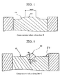
- a coating liquid 3 is ejected from a nozzle slit of a slot curtain coating head 1, made to fall freely by means of a curtain edge guide 2 (which guides the coating liquid in the form of a curtain) and brought into collision with a continuously running web 5 so as to form a coating film, as shown in FIG.
- FIGS.. 9 and 10 there are respective vacuum devices provided.
- Examples of multilayered coating methods include a method in which coating liquids with different functions are ejected from respective nozzle slits, made to fall freely by means of a pair of curtain edge guides (which guide the coating liquids in the form of a curtain) and brought into collision with a continuously running web so as to form a coating film; and a method in which coating liquids with different functions are ejected from respective slits, layered over a slide surface, made to fall freely by means of a pair of curtain edge guides (which guide the coating liquids in the form of a curtain) and brought into collision with a continuously running web so as to form a coating film.
- Typical examples of phenomena in which the stability of a curtain film is hindered include a phenomenon in which a curtain film shifts toward the back (hereinafter referred to as “teapot phenomenon”), and a phenomenon in which the thickness of a curtain film decreases in the vicinities of edge guide walls (refer, for example, to S. F. Kistler, and Schwarze "Liquid Film Coating ").
- the teapot phenomenon is a phenomenon in which a curtain film shifts toward the back of a lip instead of falling vertically. This is due to an imbalance in the momentum of a coating liquid (coating liquid flowing down a slide surface) at a lip edge.
- the teapot phenomenon is particularly noticeable when the viscosity of a coating liquid decreases or the amount thereof' applied increases, in other words when the Reynolds number is relatively large. Since both edges of the curtain film are supported by a pair of edge guides, arbitrary curving of the curtain film caused by the teapot phenomenon cannot be allowed, and thus the curtain film distorts.
- edge guide auxiliary water flow-down surface a surface along which edge guide auxiliary water flows down
- auxiliary water flow-down surface a surface along which edge guide auxiliary water flows down
- the flow-down surface has a width which is sufficient for the deformation amount of the curtain film (refer, for example, to JP-A No. 2001-46939 ).
- edge guide auxiliary water flow-down surface is a flat plate
- the falling position of the curtain film on the edge guide varies due to slight airflow in the vicinity of a curtain coating apparatus or air which accompanies a web. If the variation is great, there is a problem in that the curtain film comes into contact with ends (with respect to the width direction) of the edge guide auxiliary water flow-down surface and so the coating film thickness becomes uneven.
- the convex shape of the edge guide auxiliary water flow-down surface has a constant curvature from its upper portion to its lower portion. Therefore, when the curvature of the curtain film related to the teapot phenomenon is great, a three-dimensional liquid flow is created, the curved portion deviates greatly from the apex of the convex shape of the flow-down surface, and consequently a coating liquid flows to a portion which is away from the apex of the convex shape of the edge guide.
- the phenomenon in which the thickness of a curtain film decreases arises in the vicinities of edge guides, notably anywhere at a distance of' approximately several millimeters to approximately 10 mm from each edge guide.
- a result of research involved in the present invention has revealed that the thickness of the curtain film at such a portion is approximately 60% to approximately 95% of that of the curtain film at a central portion.
- the unevenness of film thickness is suppressed by securing a favorable balance between the tendency for the curtain film forming coating liquid to shift toward the center with respect to the width direction (which stems from the development of the boundary layer and the difference in surface tension) and the tendency for the curtain film forming coating liquid to shift toward each edge guide (which stems from the concave meniscus) (refer, for example, to Japanese Patent (JP-B) No. 2630512 ).
- the level of the coating liquid viscosity, the difference in surface tension between a curtain film central portion and curtain film edges, and the dimensions of a liquid contact portion of each edge guide are defined so as to secure a favorable balance as described above.
- this technique presents a problem in that when the static surface tension of the coating liquid is as small as approximately 35 mN/m, the curtain film deviates from the apex of the convex portion and adheres to a side surface of an edge guide owing to wind-based disturbance, thereby leading to unevenness of the curtain film. Also, this technique presents another problem in that as the coating liquid falls nonlinearly, the uniformity of a coating film is impaired, and coating unevenness arises. Further, this technique presents yet another problem in that a porous material for ejecting the edge guide auxiliary liquid is clogged with the coating liquid, thereby leading to uneven ejection of the edge guide auxiliary liquid.
- the coating liquid is attached to the porous material, it is washed off using a solvent such as hydrochloric acid.
- a solvent such as hydrochloric acid.
- this technique relates to a structure in which the edge guide auxiliary water directly flows into the ejection port and thus presents a problem in that it is difficult to eject the edge guide auxiliary water uniformly, another problem in that since the edge guide auxiliary water flow-down surface is a flat surface, the auxiliary liquid does not fall linearly and so an unstable curtain film is formed, and yet another problem in that the curtain film does not shake owing to wind-based disturbance.
- the present invention is aimed at solving the above-mentioned problems in related art and achieving the following object.
- An object of the present invention is to provide a curtain coating apparatus and a curtain coating method, which are capable of preventing distortion of a curtain film caused by the teapot effect (which is a phenomenon peculiar to curtain coating methods) and also capable of suppressing variation in the falling position of the curtain film caused by disturbance and suppressing both a film thickness decrease phenomenon and a film thickness increase phenomenon.
- the present invention is also aimed at achieving the following other object.
- Another object of the present invention is to provide a curtain coating apparatus and a curtain coating method, which are capable of preventing a curtain film from becoming unstable (which is caused by the turbulence of auxiliary water and wind-based disturbance) and also capable of suppressing increase in the thickness of the curtain film caused by a boundary layer in the vicinity of each guiding unit, even if the surface tension of the auxiliary water is low
- the present invention makes it possible to solve the above-mentioned problems in related art and achieve the object of' providing a curtain coating apparatus and a curtain coating method, which are capable of preventing distortion of a curtain film caused by the teapot effect (which is a phenomenon peculiar to curtain coating methods) and also capable of suppressing variation in the falling position of the curtain film caused by disturbance and suppressing both a film thickness decrease phenomenon and a film thickness increase phenomenon.
- the present invention also makes it possible to achieve the other object of providing a curtain coating apparatus and a curtain coating method, which are capable of preventing a curtain film from becoming unstable (which is caused by the turbulence of auxiliary water and wind-based disturbance) and also capable of suppressing increase in the thickness of the curtain film caused by a boundary layer in the vicinity of each guiding unit, even if the surface tension of the auxiliary water is low.
- a curtain coating apparatus of the present invention includes: a pair of' edge guides configured to support both side edges of at least one coating liquid so as to form a coating liquid film which falls freely and apply the coating liquid film onto a continuously running support; and an auxiliary water introduction port. If necessary, the curtain coating apparatus may further include suitably selected other unit(s).
- a curtain coating method of' the present invention includes the steps of: supporting both side edges of at least one coating liquid with a pair of edge guides so as to form a coating liquid film which falls freely and apply the coating liquid film onto a continuously running support; and introducing auxiliary water. If necessary, the curtain coating method may further include suitably selected other step(s).
- the auxiliary water introduction port allows auxiliary water to be introduced substantially uniformly with respect to a width direction of an edge guide auxiliary water flow-down surface of each edge guide from an upper portion toward a lower portion of the edge guide auxiliary water flow-down surface.
- the step of introducing auxiliary water is a step of introducing auxiliary water substantially uniformly with respect to a width direction of an edge guide auxiliary water flow-down surface of each edge guide from an upper portion toward a lower portion of the edge guide auxiliary water flow-down surface.
- the edge guide auxiliary water flow-down surface has a flat surface portion (which is substantially in the form of a flat surface) at its upper portion and has an arc-shaped portion (which is provided at a center with respect to the width direction and which protrudes in the shape of an arc) and a flat surface portion (which is provided on both sides of the arc-shaped portion with respect to the width direction) at its lower portion.
- the curvature radius of the arc-shaped portion is not particularly limited and may be suitably selected according to the intended purpose. Nevertheless, the curvature radius is preferably in the range of 2 mm to 5 mm, more preferably 3 mm to 4 mm.
- the curvature radius When the curvature radius is less than 2 mm, it may be difficult for the edge guide auxiliary water to flow down uniformly on the surface of the arc-shaped portion. When the curvature radius is greater than 5 mm, the force with which a curtain film is held on the arc-shaped portion may decrease. Conversely, when the curvature radius is in the more preferred range, there is an advantage in that the curtain film is favorably held on the arc-shaped portion of the edge guide and thus stable coating is enabled.
- the edge guide auxiliary water flow-down surface has arc-shaped areas provided along oblique sides of an inverted isosceles triangle which connect a center line (with respect to the width direction) of the arc-shaped portion with both ends of the flat surface portion provided at the upper portion of the edge guide auxiliary water flow-down surface (see FIG. 2 ).
- the distance between the auxiliary water introduction port and an apex of the isosceles triangle is not particularly limited and may be suitably selected according to the intended purpose. Nevertheless, the distance is preferably in the range of 10 mm to 35 mm, more preferably 10 mm to 25 mm.
- the distance is less than 10 mm, the distance is not sufficient to allow for curvature of the curtain film caused by the so-called teapot phenomenon at the time of the free falling of the curtain film from the lower edge of a slide die, and thus the curtain film may be disturbed.
- the distance is greater than 35 mm, the teapot phenomenon can be allowed for, but the distance between the auxiliary water introduction port and the apex of the isosceles triangle is long, so that it is difficult for the auxiliary water to flow down uniformly and thus the curtain film may be unstable.
- the distance is in the more preferred range, there is an advantage in that the teapot effect can be avoided and thus the auxiliary water flows down uniformly.
- the rate at which the auxiliary water is introduced (hereinafter referred to also as “introduction rate (of the auxiliary water)”) is not particularly limited and may be suitably selected according to the intended purpose. Nevertheless, the introduction rate is preferably in the range of 0.40 m/sec to 1.20 m/sec, more preferably 0.6 m/sec to 1.0 m/sec.
- the introduction rate When the introduction rate is lower than 0.40 m/sec, an increase in the fall velocity of the curtain film in the vicinity of each edge guide is insufficient, so that a boundary layer may be formed in the curtain film owing to the fall velocity difference between the curtain film in the vicinity of each edge guide and the curtain film at the center and thus there may be unevenness of the thickness of the curtain film.
- the introduction rate is higher than 1.20 m/sec, the amount of the edge guide auxiliary water is so large that the curtain film may be disturbed at the flat surface portion in the shape of the inverted isosceles triangle and turbulent flow may arise at the lower portion of the edge guide.
- the introduction rate is in the more preferred range, there is an advantage in that the curtain film can be made uniform and stable.
- the maximum gap of the auxiliary water introduction port with respect to the flow-down direction of the auxiliary water is not particularly limited and may be suitably selected. Nevertheless, the maximum gap is preferably in the range of 0.20 mm to 0.50 mm.
- FIG. 1 shows an example of an edge guide in the present invention.
- a slit (auxiliary water introduction port) (11) which allows edge guide auxiliary water (10) to be introduced downward and substantially uniformly with respect to a width direction of an edge guide auxiliary water flow-down surface (23).
- a curtain film (6) falls in the direction shown by the arrow, and each edge of the curtain film (6) is supported by the edge guide auxiliary water (10) that falls along the edge guide auxiliary water flowdown surface (23) of the edge guide main body (2).
- FIG. 2 shows a front elevational view of an edge guide auxiliary water flow-down portion in the present invention
- FIG. 3 shows a cross section of an upper portion thereof, taken along the line A in FIG. 2
- FIG. 4 shows a cross section of a middle portion thereof, taken along the line B in FIG. 2
- FIG. 5 shows a cross section of' a lower portion thereof, taken along the line C in FIG. 2 .
- the upper portion of the edge guide auxiliary water flow-down surface (23) has a flat surface shape (flat surface portion) (12).
- its center with respect to the width direction corresponds to the center of the coating width and is provided with an arc-ended convex portion (13)
- the arc-ended convex portion (13) has a predetermined range of' an angle ⁇ 1, and there is a flat surface shape portion (15) provided on both sides of the arc-ended convex portion (13).
- FIG. 4 there is an oblique side convex arc-shaped portion (14) formed.
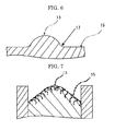
- a connecting portion provided between the arc-ended convex portion (13) and the flat surface shape portion (15) is preferably made as smooth as possible so as to secure uniformity of the fall velocity of the edge guide auxiliary water (10) with respect to the width direction.
- the connecting portion may be a connecting portion (17) as shown in FIG. 6 or may be an end of the flat surface shape portion (15), which is formed by extending a tangent to the arc of the arc-ended convex portion (13), as shown in FIG. 7 .
- the angle ⁇ 1 be in the range of 30 degrees to 90 degrees.
- the edge guide auxiliary water (10) may spread to both sides at the transitional portion between the flat surface portion (12) at the upper portion of the edge guide auxiliary water flow-down surface (23) and the arc-ended convex portion (13), and thus the edge guide auxiliary water (10) may not flow along the arc-ended convex portion (13).
- the flat surface shape of the flat surface portion (12) at the upper portion of the edge guide auxiliary water flow-down surface (23) makes it possible to allow arbitrary curving of the curtain film (6) caused by the teapot phenomenon.
- the arc-ended convex portion (13) at the lower portion of the edge guide auxiliary water flow-down surface (23) makes it possible to solve the problem of poor center adjustability of a curtain film at an edge guide.
- the flat surface portion (12) at the upper portion of the edge guide auxiliary water flow-down surface (23) and the arc-ended convex portion (13) at the lower portion thereof make it possible to solve the problems with existing edge guides at the same time.
- chord length of the arc-ended convex portion (13) is small in comparison with the width (W) of the edge guide auxiliary water flow-down surface (23). Accordingly, provision of a flat surface on both sides of the arc-shaped portion enables the fall velocity of the edge guide auxiliary water (10) (which flows down substantially uniformly with respect to the entire width of the flow-down surface) to be substantially constant with respect to the upper and lower surfaces of the flow-down surface.
- the flat surface has a function of temporarily supporting the curtain film (6) in case the curtain film (6) greatly curves owing to the teapot phenomenon or the falling position of the curtain film (6) greatly varies owing to airflow in the vicinity of the coating portion, and thus it deviates from the arc-ended convex portion (13).
- a result of research involved in the present invention has revealed that when the fall velocity of the edge guide auxiliary water (10) has a distribution with respect to the width direction, especially when the flow velocity at the center of' the edge guide auxiliary water flow-down surface is small and the flow velocity at both side edges thereof is large, there is a problem caused in that the curtain film (6) supported by the edge guide auxiliary water (10) is pulled toward both side edges owing to the difference between its velocity at the center and its velocity at both side edges, and thus it is impossible to allow the curtain film (6) to fall accurately at an intended position.
- edges of a film formed of the coating liquid applied onto a web (5) vary in coating liquid amount and thus lack linearity, thereby causing loss of coating at the edges.
- the fall velocity of the edge guide auxiliary water (10) has a distribution with respect to the width direction
- the curtain film (6) falling in such a manner as to deform owing to the teapot phenomenon is pulled toward the higher velocity sides with respect to the width direction and further deforms, which causes unevenness of the thickness of the curtain film (6) and thus causes the film (A) (formed of the coating liquid applied onto the web (5)) to vary in coating liquid amount.
- the ejection uniformity (with respect to the width direction) of the slit (11) provided in the flat surface portion (12) at the upper portion of the edge guide auxiliary water flow-down surface is important.
- the slit (11) is provided primarily in the flat surface portion, it is easy to eject the edge guide auxiliary water (10) uniformly with respect to the width direction.
- a flow path for edge guide auxiliary water (10), provided in an edge guide main body (2) basically has the same structure as the internal structure of a so-called slot die or curtain die, and the internal width thereof' is approximately the same as the ejection width of the slit (11) shown in FIG. 1 .
- the edge guide auxiliary water (10) is supplied through an inlet (not shown) to a first manifold (21) shown in FIG 8 , the flow of the edge guide auxiliary water (10) is adjusted with respect to a width direction by a second manifold (19) and slots (18) and (20), and the edge guide auxiliary water (10) is ejected through a slit (11).
- Each manifold is generally of single or double type. Employment of a manifold of double type further improves ejection uniformity with respect to the width direction.
- the width of an internal flow path is small in comparison with the ejection width of the edge guide auxiliary water, there is a large gap (0.5 mm to 1.5 mm) provided for the flow outlet, and there is a fan-shaped portion expanding in the vicinity of an exit. Therefore, conditions under which the edge guide auxiliary water flows out uniformly with respect to the width direction are limited.
- a result of research involved in the present invention has revealed that when a slit gap of approximately 0.2 mm to approximately 0.5 mm in size is provided, ejection uniformity of the slit (11) with respect to the width direction can be obtained.
- uniformity of flow velocity with respect to the width direction can be obtained by either increasing the volume of the first manifold (21) or reducing the gap for the first slot (20).
- FIG. 2 and the "C cross section" drawing of FIG. 5 both concerning an edge guide auxiliary water flow-down portion in the present invention show a shape change from the flat surface portion (12) (at the upper portion of the edge guide auxiliary water flow-down surface) to the arc-ended convex portion (13) (at the lower portion thereof).
- There is formed an inverted isosceles triangle whose oblique sides connect a center line (with respect to the width (direction) of the arc-ended convex portion (13) with both ends of the flat surface portion (12).
- Areas provided along the oblique sides of the isosceles triangle are in the shape of convex arcs with respect to the direction of the coating width center.
- the "B cross section” shown in FIG. 4 represents a part of the transitional section between the "A cross section” shown in FIG. 3 and the “C cross section” shown in FIG. 5 .
- the transitional section is not provided and there is a direct shape change from the flat surface portion (12) to the arc-ended convex portion (13), the curtain film (6) is disturbed by a large level difference at the boundary therebetween, which causes unevenness of the thickness of edges of a coating film.
- the curtain film (6) increases in center adjustability, thereby making it possible to achieve stable operation and reduce loss of coating.
- angle ⁇ 2 shown in FIG. 2 be made as small as possible.
- the angle ⁇ 2 becomes smaller, the falling direction of the curtain film trapped at the oblique sides of the isosceles triangle becomes closer to the vertical direction, and the extent of deformation of the curtain film becomes smaller. Conversely, as the angle ⁇ 2 becomes larger, it becomes easier for the curtain film trapped at the oblique sides to deform, and consequently, easier for coating unevenness to arise.
- the LL dimension at the upper portion, shown in FIG. 2 be made small as well.
- the edge guide auxiliary water does not flow down in the section represented by the LT dimension at the top, shown in FIG. 2 . Since this can encourage a decrease in the thickness of each edge of the curtain film, it is desirable that the LT dimension be small.
- the distance L between the slit (11) at the upper portion of the edge guide auxiliary water flow-down surface and the apex of the inverted isosceles triangle, shown in FIG. 2 is preferably in the range of 10 mm to 35 mm.
- the distance L is preferably 20 mm or so, in the case where the width of the edge guide auxiliary water flow-down surface (23) is 20 mm (in other words where the distance of each edge of the edge guide auxiliary water flow-down surface (23) from its center with respect to the width direction is 10 mm), under the conditions that an acrylic emulsion adhesive having a liquid viscosity of 250 mPa ⁇ s to 1,500 mPa ⁇ s and a liquid surface tension of 30 mN/m to 40 mN/m is applied at a flow rate of 1.25 cc/cm ⁇ sec to 2.5 cc/cm ⁇ sec and the edge guide auxiliary water (10) is applied in an amount of 1.00 cc/min to 300 cc/min per 6.5 mm as a width of the edge guide auxiliary water flow-down surface (23).
- the distance L is 35 mm, the curvature of the curtain film (6) caused by the teapot phenomenon can be easily allowed for.
- the distance L is so great that there tends to be an adverse effect related to the variation in the falling position of the curtain film (6) caused by wind in the vicinity of the coating portion.
- curvature radius R of the arc-like convex shape shown in FIG. 5 , be in the range of 2 mm to 5 mm.
- the curvature radius R of the arc-like convex shape provided along each oblique side of the inverted isosceles triangle is not particularly limited.
- this curvature radius R is (approximately) equal to the curvature radius R of' the arc-like convex shape shown in FIG. 5 , facilitation can be yielded in terms of processing and production, and the production cost of the edge guide can thereby be reduced.
- the width of the edge guide auxiliary water flow-down surface (23) is preferably in the range of 7 mm to 20 mm.
- a result of research involved in the present invention has revealed that the curtain film (6) does not come into contact with edges of the edge guide auxiliary water flow-down surface (23) with respect to the width direction, in the case where the width of the edge guide auxiliary water flow-down surface (23) is 20 mm (in other words where the distance of each edge of the edge guide auxiliary water flow-down surface (23) from its center with respect to the width direction is 10 mm), under the conditions that an acrylic emulsion adhesive having a liquid viscosity of 250 mPa s to 1,500 mPa ⁇ s and a liquid surface tension of 30 mN/m to 40 mN/m is applied at a flow rate of 1.25 cc/cm ⁇ sec to 2.5 cc/cm ⁇ sec and the edge guide auxiliary water (10) is applied in an amount of 100 cc/min to 300 cc/min per 6.5 mm as a width of the edge guide auxiliary water flow-down surface (23).
- the ejection velocity at the slit (11) can be freely set, and a result of research involved in the present invention has revealed that the fall velocity of both edges of the curtain film (6) supported by the edge guide main body (2) can be freely set.
- auxiliary water is ejected substantially uniformly from an upper portion toward a lower portion of an edge guide auxiliary water flow-down surface.
- auxiliary water is ejected at a velocity of approximately 0.5 cm/sec to approximately 2.0 cm/sec (ejection amount: 50 cc/min to 200 cc/min, edge guide height: 150 mm), which is low in comparison with a fall velocity of approximately 1.6 m/sec at a central portion with respect to the curtain width direction (fall height: 150 mm), and a curtain film is mixed with the auxiliary water that has been ejected from an upper poition and accelerated by gravity and that is falling at an increased velocity, which is thought to be a cause of formation of a thin film portion.
- edge guide of the present invention makes it possible to freely set the flow-down ejection velocity of the edge guide auxiliary water in the range of 40 cm/sec to 120 cm/sec.
- the thickness of the thin film portion in the vicinity of each edge guide can be made sufficiently large.
- the thickness of the thin film portion can be controlled by changing the ejection velocity.
- increase in the thickness of the curtain film can be reduced at the same time by setting the flow-down ejection velocity of the edge guide auxiliary water in the range of 40 cm/sec to 120 cm/sec as described above, which negates any relationship between the fall velocity of the curtain film in the vicinity of each edge guide and the boundary layer and which thereby reduces a liquid flow related to a surface tension gradient on the curtain film surface that causes decrease in the thickness of the curtain film.
- the mechanism for increase in the film thickness has been unclear as yet, it is impossible to clearly explain the mechanism for reducing increase in the film thickness at this moment in time.
- a curtain coating apparatus of the present invention is intended for web coating and includes an ejecting unit, a pair of guiding units and a conveying unit. If necessary, the curtain coating apparatus may further include suitably selected other unit(s)
- a curtain coating method of the present invention is intended for web coating and includes an ejecting step, a guiding step and a conveying step. If necessary, the curtain coating method may further include suitably selected other step(s).
- the ejecting unit is a unit having a coating liquid ejection port, configured to eject a coating liquid from the coating liquid ejection port.
- the ejecting step is a step of ejecting a coating liquid from a slit
- the coating liquid is not particularly limited and may be suitably selected according to the intended purpose. Examples thereof include acrylic emulsions, heat-sensitive liquids, thermal transfer ribbon coating liquids, aqueous coating liquids and solvent coating liquids.
- the appropriate viscosity range varies depending upon whether a slot die curtain coating apparatus or a slide die curtain coating apparatus is used as the curtain coating apparatus. Also, in the curtain coating method, the viscosity of the coating liquid needs to be adjusted to the appropriate viscosity range.
- the coating liquid preferably has a low-shear viscosity of 1 mPa ⁇ s to 2,000 mPa ⁇ s.
- the coating liquid preferably has a viscosity of 1 mPa ⁇ s to 500 mPa ⁇ s.
- its viscosity is preferably in the above-mentioned low-shear viscosity range,
- the viscosity of the coating liquid when the viscosity of the coating liquid is low, liquid drips from slits of the die in the case where coating is temporarily ceased for adjustment or the like during an operation.
- the viscosity of the coating liquid is greater than 2,000 mPa ⁇ s, (1) air bubbles in the liquid are hard to remove, thereby possibly causing a bubble-related defect caused by the air bubbles in the liquid, and (2) the ejection pressure of the coating liquid increases, so that there is a higher load on a liquid-sending pump and the liquid supply system needs pressure resistance.
- the viscosity of the coating liquid is preferably low in view of' film thickness uniformity.
- the coating liquid flows slowly in the vicinity of a slide portion edge guide (denoted by the numeral 109 in FIG. 12 ) while flowing down a slide portion, and a boundary layer is formed as mentioned above, so that the coating liquid has an increased film thickness portion owing to viscous resistance while flowing down the slide portion.
- the coating liquid When the viscosity of the coating liquid is greater than 500 mPa ⁇ s, the coating liquid has a film thickness increased by over 20% in the area apart from the edge by 10 mm to 40 mm, compared to the coating liquid at the central flat portion, owing to the film thickness increasing mechanism while the coating liquid flows down the slide portion, and thus there arises a defect related to the unevenness of the film thickness, which leads to winding failure and/or drying failure.
- the viscosity can be measured using a B-type viscometer or the like, for example.
- the surface tension of' the coating liquid is not particularly limited and may be suitably selected according to the intended purpose. Nevertheless, it is preferably in the range of 20 mN/m to 40 mN/m.
- the surface tension is less than 20 mN/m, the surface tension of the film itself is low, so that the film is slack and thus the film easily deforms and shakes owing to wind-based disturbance.
- the surface tension is greater than 40 mN/m, the curtain film deforms in an upward direction.
- the surface tension can be measured as a static surface tension in a platinum plate method, using a Face automatic surface tensiometer (manufactured by Kyowa Interface Science Co., Ltd) or the like, for example. Also, as described in " A study of the behavior of a thin sheet of' moving liquid J. Fluid Mechanics, 10:297-305 ", the dynamic surface tension of the curtain film can be measured by means of the split angle of the film obtained by inserting needle-like foreign matter into the curtain film.
- the deformation is caused depending upon the balance between the dynamic pressure and the dynamic surface tension of the curtain film, and so it is important to measure and evaluate the dynamic surface tension of the film.
- the coating liquid slit is rectangular in cross-sectional shape.
- the size of the coating liquid ejection port is not particularly limited and may be suitably selected according to the intended purpose. Nevertheless, the slit preferably has a gap of approximately 0.2 mm to approximately 0.5 mm.
- the gap of the slit has a function of making uniform the coating liquid with respect to the width direction.
- the size of the gap varies depending upon the size and shape of a die manifold, the distance between the manifold and the outlet of the slit, the presence or absence of a second manifold, the position of the second manifold, the flow rate and viscosity of the coating liquid, and the like, as described in " Slot Coating: Fluid mechanics and die design, Sartor, Luigi, Ph.D. University of Minnesota, 1990 ", etc.
- the material for the coating liquid ejection port is not particularly limited and may be suitably selected according to the intended purpose.
- the coating liquid ejection port preferably has a metal surface such as of SUS, aluminum or plating such as hard chromium plating.
- the material is preferably a metal because clogging can be prevented even if the coating liquid contains resin.
- An ejection mechanism for ejecting the coating liquid may be a slot die curtain coating apparatus or a slide die curtain coating apparatus, and the ejection mechanism is suitably selected from these according to the intended use.
- the slot die curtain coating apparatus is used to apply one or two layers of coating liquid(s).
- the slot die curtain coating apparatus has a slit which faces downward, so that when the viscosity of the coating liquid is low, liquid dripping may arise and air bubbles in the liquid may remain in a manifold of a die head. Nevertheless, the slot die curtain coating apparatus is higher in the ejection velocity of the coating liquid than the slide die curtain coating apparatus; therefore, in view of the mechanism in which the curtain film deforms in an upward direction when there is great dynamic surface tension, which is related to the balance between the dynamic surface tension of the coating liquid and the dynamic pressure (inertial force) at the time of the fall of the coating liquid, the coating liquid used with the slot die curtain coating apparatus does not easily deform in an upward direction.
- a releasing space such as a slide flow-down surface is not provided, so that washing can be facilitated and the amount of washing liquid used for the washing (such as water) is small.
- the viscosity of the coating liquid is high, coating can be temporarily ceased with ease during an operation.
- the slide die curtain coating apparatus is used to apply one or more layers (possibly three or more layers) of coating liquid(s).
- the slide die curtain coating apparatus has a slit which faces upward, so that bubbles do not easily accumulate in a manifold of a die head.
- the area of a slide portion is large, washing is not easy, and a large amount of washing liquid is required at the time of a cessation of coating during an operation in comparison with the slot die curtain coating apparatus..
- the flow rate of the coating liquid ejected is not particularly limited as long as the curtain film can be formed, and the flow rate may be suitably selected according to the intended purpose.
- the slot die curtain coating apparatus is not problematic as long as the coating liquid is ejected at an intended flow rate and the apparatus has portions in the forms of the slit and the manifold that are capable of forming the curtain film.
- the slide die curtain coating apparatus is not problematic as long as it has portions in the forms of the slit and the manifold that enable the coating liquid to be ejected at an intended flow rate, and (after the coating liquid is ejected from the slit and then flows down a slide surface) the curtain film can be formed.
- an upper portion of the curtain film has an increased film thickness portion, so that it is necessary to appropriately set the width (shown by the letter W in FIG. 16 ) of a groove of the edge guide, at the upper portion of the edge guide, according to the flow rate.
- the guiding unit is a unit (102) including an auxiliary water introduction port (114) through which auxiliary water is introduced, configured to support both edges of a curtain film with respect to a width direction substantially perpendicular to the direction in which a curtain film (106) formed of the coating liquid flows down (direction of the arrow in FIG. 15 ), and guide the curtain film (106) onto a support (105) conveyed.
- the guiding step is a step of supporting both edges of a curtain film with respect to a width direction substantially perpendicular to the direction in which the curtain film (106) formed of the coating liquid flows down (direction of the arrow in FIG. 15 ), and guiding the curtain film (106) onto the support (105) conveyed, by using the pair of guiding units (102) each having the auxiliary water introduction port (114) through which auxiliary water is introduced.
- the guiding unit includes an auxiliary water flow-down groove (concave portion) (116) through which the auxiliary water flows down.
- An auxiliary water flow-down groove side surface (concave portion side surface) (116b) formed substantially perpendicularly to a bottom surface (116a) of the auxiliary water flow-down groove (concave portion) (116) forms an acute angle ⁇ with an exposed surface (121) formed so as to be continuous with the auxiliary water flow-down groove side surface (concave portion side surface) (116b) and intersect the auxiliary water flow-down groove side surface (concave portion side surface) (116b).
- each guiding unit preferably has a flat surface (140) (which measures 5 mm to 15 mm long and 7 mm or more wide) above the auxiliary water introduction port (114) with respect to the direction in which the auxiliary water flows down.
- a flat surface (140) which measures 5 mm to 15 mm long and 7 mm or more wide
- this flat surface (140) it is possible to avoid curving of the curtain film caused by the difference in velocity between the curtain film at a slide surface and the curtain film at a free surface (the teapot effect).
- auxiliary water it is necessary to appropriately select the auxiliary water according to the coating liquid. It is necessary for the auxiliary water to be higher in surface tension than the coating liquid in order to exhibit an effect of holding the curtain film on the edge guide (so called center adjustability) by the auxiliary water pulling the coating liquid.
- auxiliary water include aqueous liquids such as water, and (in the case where the coating liquid is a solvent-like substance) a liquid prepared by mixing together a solvent, water, a resin, a surfactant, etc.
- the maximum gap of the auxiliary water introduction port (shown by the letter G in FIG. 16 ) with respect to the direction in which the auxiliary water flows down is not particularly limited and may be suitably selected according to the intended purpose. Nevertheless, it is preferably in the range of 0.2 mm to 0.5 mm, more preferably 0.2 mm to 0.4 mm.
- the maximum width of the auxiliary water introduction port (shown by the letter W in FIG. 16 ) with respect to a direction perpendicular to the direction in which the auxiliary water flows down is not particularly limited and may be suitably selected according to the intended purpose. Nevertheless, it is preferably in the range of 1.5 mm to 4 mm, more preferably 2 mm to 3 mm.
- the maximum width is smaller than 1.5 mm, there may be a problem with processing accuracy.
- the maximum width is larger than 4 mm, the auxiliary water may not uniformly flow with respect to the entire width.
- the introduction rate of the auxiliary water is not particularly limited as long as the auxiliary water flows along the flow-down surface, and the introduction rate may be suitably selected according to the intended purpose. Nevertheless, it is preferably in the range of 0.4 m/sec to 21 m/sec, more preferably 0.8 m/sec to 1.6 m/sec.
- the introduction rate When the introduction rate is lower than 0.4 m/sec, there may be a boundary layer formed When the introduction rate is higher than 2.1 m/sec, the auxiliary water may be introduced diagonally and downward.
- the auxiliary water flow-down surface has an auxiliary water flow-down groove (concave portion)
- the auxiliary water flow-down surface is small in width and there are wall surfaces on both its sides, so that the auxiliary water can be favorably held and the fall velocity of the auxiliary water can be increased, in comparison with the case (first embodiment) where the auxiliary water flow-down surface has an arc-ended convex shape
- the auxiliary water can be made to flow down uniformly with respect to the entire width of the flow-down surface. Provided that the introduction rate of the auxiliary water does not vary, the amount of the ejected auxiliary water can be reduced because of the small width of the flow-down surface
- the auxiliary water introduction port is in the form of a slit which is rectangular in cross-sectional shape. It is preferred that the flow path in the edge guide be in the form of a long slit. However, in the case where the slit is long, cleaning becomes difficult if clogging arises also, in reality, it is difficult to provide a long slit on the inside from a structural point of view.
- a manifold on the inside of the edge guide, as shown in FIG. 17 .
- the provision of a second manifold makes it possible for the auxiliary water to move a shorter distance to reach the auxiliary water introduction port, thereby making it possible to eject the auxiliary water uniformly.
- the material for the auxiliary water introduction port is not particularly limited and may be suitably selected according to the intended purpose Nevertheless, the material is preferably a metal because clogging can be prevented even if the coating liquid contains resin.
- the auxiliary water flow-down groove includes a bottom surface, and a concave portion side surface formed substantially perpendicularly to the bottom surface.
- the concave portion side surface forms an acute angle with an exposed surface formed so as to be continuous with the concave portion side surface and intersect the concave portion side surface.
- the acute angle is not particularly limited as long as it is smaller than 90°, and it may be suitably selected according to the intended purpose. Nevertheless, it is preferably in the range of 30° to 80°, more preferably 45° to 60°.
- the acute angle When the acute angle is smaller than 30°, there may be adverse effects in terms of processing accuracy. When the acute angle is larger than 80°, the effects of the acute angle may be impaired, Conversely, when the acute angle is in the more preferred range, there is an advantage in that the edge guide auxiliary water can be favorably held.
- the maximum depth of the auxiliary water flow-down groove (concave portion) (shown by the letter h in FIG. 19 ) is not particularly limited and may be suitably selected according to the intended purpose Nevertheless, it is preferably in the range of 0.2 mm to 0.5 mm, more preferably 0.2 mm to 0.35 mm.
- the auxiliary water may overflow the auxiliary water flow-down groove (concave portion)
- turbulent flow may arise.
- the maximum distance between the auxiliary water flow-down groove side surface (concave portion side surface) and the other auxiliary water flow-down groove side surface (concave portion side surface) is not particularly limited and may be suitably selected according to the intended purpose. Nevertheless, it is preferably in the range of 15 mm to 4.0 mm, more preferably 2 mm to 3 mm.
- the auxiliary water may flow with difficulty and overflow the concave portion.
- the curtain film may be unstable, and turbulent flow may arise at the lower portion.
- the support is not particularly limited as long as it can support the coating liquid, and it may be suitably selected according to the intended purpose.
- the shape, structure and size of the support are not particularly limited and may be suitably selected according to the intended purpose.
- Examples of the support include release paper, base paper, synthetic paper and PET film.
- the conveying unit is a unit configured to convey the support.
- the conveying step is a step of conveying the support.
- FIG.. 12 shows an example of a slide curtain coating apparatus as a curtain coating apparatus of the present invention.
- a slide curtain coating apparatus (curtain coating head) (107) includes slots (110) and (111), manifolds (112) and (113) and slits (not shown), provided as ejecting units configured to eject a coating liquid (103). These ejecting units eject the coating liquid (103) onto a slide surface (108), the coating liquid (103) flows on the slide surface (108) and then freely falls from the slide surface (108) so as to form a curtain film (106) and then form a coating film on a continuously running web (base material) (105).
- the web (105) is conveyed by means of a conveying unit (not shown)
- a slide portion edge guide (guiding unit) (109) At sides of the slide surface (108) is provided a slide portion edge guide (guiding unit) (109), and at sides of the curtain film (106) is provided a curtain portion edge guide (guiding unit) (102) configured to hold each edge of the curtain film (106).
- a slide curtain coating apparatus (curtain coating head) (107) has a plurality of manifolds (112) and (113) and a plurality of slots (110) and (111).
- the plurality of manifolds (112) and (113) and the plurality of slots (110) and (111) allow a coating liquid (103) to be ejected onto a slide surface (108), and the coating liquid (103) is layered on the slide surface (108).
- the layered coating liquid (103) freely falls from the slide surface (108) so as to form a curtain film (106) and then form a coating film on a continuously running web (base material) (105).
- FIG. 13 is a drawing showing an example of a slot curtain coating apparatus as a curtain coating apparatus of the present invention..
- a coating liquid is ejected from a manifold (112) and a slot (110) provided in a slot curtain coating head (101), and the coating liquid flows down as a curtain film (106), with its each edge held by an edge guide (102), then comes into collision with a base material (105) and is thus applied to the base material (105).
- a coating liquid is ejected from a manifold (113), a slot (110) and a slit (not shown) provided in a slide curtain coating head (107), and the coating liquid flows on a slide surface (108), subsequently flows down with its each edge held by an edge guide main body (102), then comes into collision with a base material (105) and is thus applied to the base material (105).
- a coating liquid is ejected onto a slide surface (108), and the coating liquid is layered on the slide surface (108)
- the layered coating liquid freely falls from the slide surface (108) so as to form a curtain film (106) and then form a coating film on a continuously running web (105).
- an edge guide main body (102) has at its upper portion an auxiliary water introduction port (114) which allows auxiliary water (115) to be ejected in a downward direction and substantially uniformly with respect to the width direction of an auxiliary water flow-down groove (concave portion) (116).
- the auxiliary water introduction port (114) is rectangular in cross-sectional shape and is placed perpendicularly to a curtain film (106) and perpendicularly to the direction in which the curtain film (106) falls down.
- the curtain film (106) falls in the direction of the arrow, and both its edges are supported by the auxiliary water (115) which falls inside the auxiliary water flow-down groove (concave portion) (116) of the edge guide main body (102).
- the introduction rate of the auxiliary water (115) is set by changing the opening degree of' a flow rate adjusting valve (not shown) or changing the ejection amount of a pump
- a discharge port (not shown) which allows a mixed liquid composed of the auxiliary water (115) and a coating liquid to discharge, and a vacuum mechanism (not shown) which makes it easy for the mixed liquid to discharge are provided.
- auxiliary water for preventing adhesion of the coating liquid may be applied.
- FIG. 16 is a front elevational view of an edge guide main body (102), and FIG. 19 is a cross-sectional view of the edge guide main body (102).
- the letter W denotes the maximum distance between a concave portion side surface (116b) and the other concave portion side surface (116b) of the edge guide main body (102) (the maximum width of an auxiliary water flow-down groove (concave portion) (116), the maximum width of an auxiliary water introduction port (114)), and the letter h denotes the maximum depth of the auxiliary water flow-down groove (concave portion) (116),
- An end (190) has an acute angle ⁇ .
- the end may have a flat portion of approximately 0.1 mm in size in view of processing accuracy or have a curved surface (R) of approximately several tens of micrometers to 100 ⁇ m in size so as to reduce the amount of a burr or flash.
- R curved surface
- the gap of an auxiliary water introduction port (114) is adjusted to 0.2 mm, and there is a level difference provided such that the distance of a bottom surface (116a) of an auxiliary water flow-down groove (concave portion) (116) from a curtain film and a joint surface (170) at an upper portion of an edge guide is in the approximate range of 0,2 mm to 0.5 mm.
- a manifold is provided in at least one place inside the edge guide, thereby allowing auxiliary water to be ejected uniformly with respect to the width direction.
- the bottom surface of the auxiliary water flow-down groove of the edge guide is preferably a metal surface such as of SUS, aluminum or plating such as hard chromium plating. Other parts thereof may be made of hydrophilic material or hydrophobic material.
- edge guide can be applied to both slide curtain coating apparatuses (as shown in FIG. 12 ) and slot curtain coating apparatuses (as shown in FIGS. 13 and 14 ).
- the bottom surface and the side surfaces of the auxiliary water flow-down groove are made of metal instead of porous material, the problem of clogging of' the porous material with a coating liquid can be solved, and center adjustability can be exhibited by the surface tension of the auxiliary water, not by the surface tension of the coating liquid. Therefore, by providing the auxiliary water flow-down groove (concave portion), it is possible to form a curtain film which is stable against wind-based disturbance. Also, by introducing the auxiliary water in the falling direction of the curtain film and along edges of the curtain film at an initial introduction rate of 0.4 m/sec to 1,6 m/sec, it is possible to further suppress formation of a boundary layer in the curtain film.
- the edge guide in the present invention can be applied to both slide curtain coating apparatuses (as shown in FIG. 12 ) and slot curtain coating apparatuses (as shown in FIGS. 13 and 14 ). It should, however, be noted that in the case where the edge guide in the present invention is applied to a slide curtain coating apparatus, it is necessary to avoid curving of the curtain film caused by the difference in velocity between the curtain film at the slide surface (108) and the curtain film at the free surface (the teapot effect), when the coating liquid has flowed on the slide surface (108) and forms a freely falling liquid film
- a width of at least 3 mm is required alongside the auxiliary water introduction port and ahead of the curtain film, and a width of at least 1 mm is required alongside the auxiliary water introduction port and behind the curtain film, which means that a total width of' at least 7 mm (the sum of the above-mentioned widths and the width (3 mm) of the auxiliary water introduction port) is required.
- a length of at least 5 mm is required above the auxiliary water introduction port, and (depending upon the flow rate of the coating liquid) a length of approximately 5 mm to approximately 15 mm is required above the auxiliary water introduction port.
- a flat surface which measures 5 mm to 15 mm long and 7 mm or more wide is preferably formed at the upper portion of the edge guide, extending from the lower edge of the slide curtain die.
- a metal surface is employed as this flat surface, a hydrophilic or hydrophobic surface may be employed.
- the auxiliary water may be applied onto the flat surface.
- auxiliary water introduction port (114) It is necessary for the auxiliary water introduction port (114) to be in the shape of a straight line (slit) which is perpendicular to the width direction of the curtain film (106) and perpendicular to the falling direction of the curtain film (106).
- the edge guide shown in FIG. 2 was used
- Width W of the edge guide auxiliary water flow-down surface 14 mm
- edge guide auxiliary water flow-down surface and side plates at both ends of the edge guide auxiliary water flow-down surface were polished in the flow-down direction of the edge guide auxiliary water, using sandpaper (#1500).
- Comparative Example A-1 was the same as Example A-1 except that the flat plate edge guide (in which a slide portion is formed of an SUS plate instead of' glass) mentioned in JP-A No. 2001-46939 was used.
- Width W of the edge guide auxiliary water flow-down surface 14 mm
- edge guide auxiliary water flow-down surface and side plates at both ends of the edge guide auxiliary water flow-down surface were polished in the flow-down direction of the edge guide auxiliary water, using sandpaper (#1500).
- Comparative Example A-2 was the same as Example A-1 except that the edge guide (manufactured by Polytype Ltd in Switzerland) mentioned in International Publication No. WO2008/000507 was used.
- Width of the edge guide auxiliary water flow-down surface 6.5 mm
- Table 1 Presence or absence of distortion of curtain film caused by teapot effect Presence or absence of variation in falling position of curtain film caused by disturbance wind
- Example A-1 A There was no distortion. The curtain film had a curved portion (approx 5 mm in width and approx 20 fall down distance) owing to the teapot effect and subsequently had a perpendicular falling portion. A: There was no positional variation. Comparative Example A-1 A: There was no distortion The curtain film had a curved approx. portion (approx. 5 mm in width and 3 and approx. 35 mm in fall down distance) owing to the teapot effect and subsequently had a perpendicular falling portions. B: There was a great positional variation.
- Comparative Example A-2 B The curtain film had a curved portion (approx 5 mm in width) owing to the teapot effect, slightly touched the side plates at both ends of the edge guide auxiliary water flow-down surface, and thus distorted A: There was no positional variation.
- the curtain edge guide main body was tilted in the direction of a surface which was at right angles to the coating width direction.
- Coating liquid thermosensitive layer liquid for thermal paper ⁇ solid content concentration (S.C.): 9.9%, viscosity: 250 mPa ⁇ s (B-type viscometer), liquid surface tension: 39 mN/m (static surface tension* in a platinum plate method); * the static surface tension was measured using the Face automatic surface tensiometer CBVP-A3 (manufactured by Kyowa Interface Science Co., Ltd) ⁇ • 3-dibutylamino-6-methyl-7-anilinofluoran parts 4 • 4-isopropoxy-4'-hydroxydiphenylsulfone 12 parts • Silica parts 6 • 10% aqueous solution of polyvinyl alcohol parts 16 • Water parts 41
- Example A-2 was the same as Example A-1 except that the length of R was changed from 5 mm to 3 mm.
- Example A-3 was the same as Example A-1 except that the length of R was changed from 5 mm to 2 mm.
- Example A-4 was the same as Example A-1 except that the length of R was changed from 5 mm to 5.5 mm.
- Example A-5 was the same as Example A-1 except that the length of R was changed from 5 mm to 15 mm. Table 2 Tilt angle of curtain film held (°) Evaluation Example A-1 15 A Example A-2 18 A Example A-3 13 A Example A-4 7 B Example A-5 8 B
- Example A-6 was the same as Example A-1 except that the position of the edge guide was shifted by 2 mm toward the upstream side with respect to the base material traveling direction.
- Example A-7 was the same as Example A-1 except that the length of L was changed from 33 mm to 10 mm.
- Example A-8 was the same as Example A-1 except that the length of L was changed from 33 mm to 5 mm.
- Example A-9 was the same as Example A-1 except that the length of L was changed from 33 mm to 40 mm.
- Example A-10 was the same as Example A-1 except that the length of L was changed from 33 mm to 145 mm.
- Example A-6 The curtain film had a curved portion, trapped at the oblique sides of the isosceles triangle for approx. 10 mm, owing to the teapot effect and subsequently had a perpendicular falling portion along the apex of the arc-ended convex portion.
- the curtain film was not abnormal
- a Example A-7 The curtain film had a curved portion, trapped at the oblique sides of the isosceles triangle for approx. several millimeters, owing to the teapot effect and subsequently had a perpendicular falling portion along the apex of the arc-ended convex portion.
- the curtain film was not abnormal.
- Example A-8 The curtain film had a curved portion (approx 5 mm in width) owing to the teapot effect, and there was a case confirmed where the curtain film immediately fell outside the arc-ended convex portion.
- B Example A-9 The curtain film had a curved portion (approx 5 mm in width) owing to the teapot effect, and there were a case confirmed where the curtain film fell perpendicularly along the flat surface portion and then fell perpendicularly along the surfaces at the sides of the arc-ended convex portion, and a case confirmed where the curtain film fell in the vicinity of the apex of the arc-ended convex portion.
- B Example A-10 The curtain film was tapped at the oblique sides of the isosceles triangle, and there was a case confirmed where the curtain film did not fall perpendicularly but fell diagonally.
- the ejection velocity was calculated from the ejection flow rate and the cross-sectional area of the slit through which the edge guide auxiliary water was ejected.
- the measurement was carried out at positions which were apart from the edge guide by 5 mm, 15 mm and 125 mm respectively.
- Example A-11 was the same as Example A-1 except that the introduction rate of the auxiliary water was changed from 0.40 m/sec to 0.80 m/sec.
- Example A-12 was the same as Example A-1 except that the introduction rate of the auxiliary water was changed from 0.40 m/sec to 1.20 m/sec.
- Example A-13 was the same as Example A-1 except that the introduction rate of the auxiliary water was changed from 0.40 m/sec to 0.20 m/sec.
- Example A-14 was the same as Example A-1 except that the introduction rate of the auxiliary water was changed from 0.40 m/sec to 1.60 m/sec.
- Example A-15 was the same as Example A-1 except that the introduction rate of the auxiliary water was changed from 0.40 m/sec to 0.35 m/sec
- Example A-16 was the same as Example A-1 except that the introduction rate of the auxiliary water was changed from 0.40 m/sec to 1.25 m/sec.
- the curtain fall velocity was measured at a position which was apart from the lower edge of the curtain die lip by 140 mm.
- Measuring apparatus MODEL 1110A, manufactured by ACT Electronics Corp.
- Example A The relative velocity was 95% or greater.
- B The relative velocity was 90% or greater but less than 95%
- B The relative velocity was less than 90%.
- Table 4 Distance from edge guide Evaluation 5 mm 15 mm 125 mm Example A-1 95.7% 99.6% 100.0% A Example A-11 997% 99.8% 100.0% A Example A-12 102.3% 998% 100.0% A Example A-15 94.2% 99.7% 100.0% B
- Example A-16 103.1% 100.3% 100.0%
- Example A-13 94.5% 100.7% 100.0%
- Example A-14 1082% 99.9% 100.0%
- Comparative Example A-2 88.6% 98.8% 100.0% C
- the edge guide auxiliary water was introduced at two introduction rates as shown below
- Example A-17 was the same as Example A-1 except that the introduction rate of the auxiliary water was changed from 0.40 m/sec to 0.80 m/sec and the size of the gap for the edge guide auxiliary water inlet was changed from 0.35 mm to 0.2 mm.
- Example A-18 was the same as Example A-1 except that the introduction rate of the auxiliary water was changed from 0.40 m/sec to 0,80 m/sec and the size of the gap for the edge guide auxiliary water inlet was changed from 0,35 mm to 0.5 mm.
- Example A-19 was the same as Example A-1 except that the introduction rate of the auxiliary water was changed from 0,40 m/sec to 0.80 m/sec and the size of the gap for the edge guide auxiliary water inlet was changed from 0.35 mm to 0,1 mm.
- Example A-20 was the same as Example A-1 except that the introduction rate of the auxiliary water was changed from 0.40 m/sec to 0,80 m/sec and the size of the gap for the edge guide auxiliary water inlet was changed from 0.35 mm to 0.6 mm.
- Example A-21 was the same as Example A-1 except that the introduction rate of the auxiliary water was changed from 0.40 m/sec to 1.2 m/sec and the size of the gap for the edge guide auxiliary water inlet was changed from 0.35 mm to 0.2 mm.
- Example A-22 was the same as Example A-1 except that the introduction rate of the auxiliary water was changed from 0.40 m/sec to 1.2 m/sec and the size of the gap for the edge guide auxiliary water inlet was changed from 0.35 mm to 0.5 mm.
- Example A-23 was the same as Example A-1 except that the introduction rate of the auxiliary water was changed from 0,40 m/sec to 1.2 m/sec and the size of the gap for the edge guide auxiliary water inlet was changed from 0.35 mm to 0.1 mm.
- Example A-24 was the same as Example A-1 except that the introduction rate of the auxiliary water was changed from 0.40 m/sec to 1.2 m/sec and the size of the gap for the edge guide auxiliary water inlet was changed from 0.35 mm to 0.6 mm.
- Table 6 Ejection and flow down state of auxiliary water Evaluation Example A-17 The edge guide auxiliary water was ejected uniformly with respect to the entire width and flowed down for almost the entire width of the flow-down surface.
- a Example A-18 The edge guide auxiliary water was ejected uniformly with respect to the entire width and flowed down for almost the entire width of the flow-down surface.
- Example A-19 The edge guide auxiliary water was not uniformly ejected from the exit of the inlet, and there was a case where part of the auxiliary water flowed down diagonally, thereby causing the flow of the curtain film to distort.
- B Example A-20 There was a case where the edge guide auxiliary water did not flow down for the entire width of the flow down surface and mixed with the curtain film, at a lower portion of the flow-down surface.
- B Table 7 Ejection and flow down state of auxiliary water Evaluation Example A-21 The edge guide auxiliary water was ejected uniformly with respect to the entire width and flowed down for almost the entire width of the flow-down surface.
- a Example A-22 The edge guide auxiliary water was ejected uniformly with respect to the entire width and flowed down for almost the entire width of the flow-down surface.
- a Example A-23 The edge guide auxiliary water was not uniformly ejected from the exit of the inlet, and there was a case where part of the auxiliary water flowed down diagonally, thereby causing the flow of the curtain film to distort.
- B Example A-24 There was a case where the edge guide auxiliary water did not flow down for the entire width of the flow-down surface and mixed with the curtain film, at a lower portion of the flow-down surface.
- the auxiliary water flowed down substantially uniformly with respect to the entire width of the flow-down surface, at introduction rates of 0.8 m/sec and 1.2 m/sec.
- the auxiliary water was not uniformly introduced from the introduction port, and there was a case where part of the auxiliary water flowed down diagonally, thereby causing the flow of the curtain film to distort.
- curtain coating was carried out under the conditions below, using the slide die curtain coating apparatus shown in FIG. 12 , and the following were evaluated: (i) the stability of the curtain film against disturbance such as wind; (ii) the presence or absence of turbulent flow in the vicinity of the edge guide; (iii) the presence or absence of a phenomenon in which the edge guide auxiliary water did not flow on the entire surface (a phenomenon in which the auxiliary water flowed in the form of a string), and of turbulent flow at a lower portion of the edge guide; and (iv) the flow rate distribution of the curtain film with respect to the width direction.
- the evaluation results are shown in Tables 8 to 13.
- the position of the edge guide could be shifted, and the falling position of the curtain film was adjusted to one side of an end of the edge guide.
- an acrylic emulsion adhesive product name: X-407-102E-10, manufactured by SAIDEN CHEMICAL INDUSTRY CO., LTD.
- the liquid viscosity of the coating liquid was 450 mPa ⁇ s.
- the static surface tension (in a platinum plate method) of the coating liquid was 33 mN/m.
- the flow rate of the coating liquid was adjusted to 1.75 cc/(cmxsec).
- the width of the curtain film (curtain fall width) was adjusted to 230 mm.
- the edge guide was made to have the cross-sectional shape shown in FIG. 19 , and the angle ⁇ in FIG. 19 was set at 60°.
- the size of the edge guide was set such that the flow-down surface length L ( FIG. 16 ) was 145 mm, the maximum gap G ( FIG. 16 ) of the auxiliary water introduction port was 0.2 mm, the maximum width W ( FIG. 16 ) of the auxiliary water introduction port was 3 mm, the maximum depth h ( FIG. 19 ) of the auxiliary water flow-down groove (concave portion) was 0.5 mm and the maximum width W ( FIG. 19 ) of' the auxiliary water flow-down groove (concave portion) was 3 mm.
- the material for the edge guide was SUS420J2.
- the edge guide auxiliary water was supplied from a pressurized tank which was pressurized to 0.2 MPa to the edge guide via a micro-motion flowmeter (manufactured by OVAL Corporation) (flowmeter main body: E010S-SS-311, transmitter: RFT9739-3MD11, integrator: EL0122-132011) and a float-type flowmeter (P100L-4, manufactured by TOKYO KEISO CO.,LTD), The opening degree of a metering valve of the float-type flowmeter was adjusted and, by means of conversion from the flow rate, the introduction rate of the edge guide auxiliary water was set at 0.8 m/sec
- a wind of approximately 0.5 m/s in wind velocity was applied in two directions, i.e, from in front of the curtain film to the curtain film perpendicularly, and from in front of the curtain film to the vicinity of the edge guide, and evaluations were thus carried out.
- the foregoing wind velocity was set as a result of supposing airflow in the vicinity of the coating head caused, for example, by air which accompanies a rotating base material on a roll, and airflow caused at the time of operations such as movement of' an operator of the coating apparatus and adjustment of a gap in the vicinity of the coating apparatus.
- Example B-1 employing the edge guide having the shape in FIG. 19 yielded greater pinning effects on the edge guide auxiliary water at the edges than Comparative Example B-1 employing the edge guide having the shape in FIG. 18 (the angle ⁇ in FIG. 19 is 90°).
- Example B-1 to B-3 turbulent flow did not arise, whereas in Example B-4, there was a case where turbulent flow arose. Meanwhile, in Example B-5, there was a case where the edge guide auxiliary water overflowed at the upper portion and, in Example B-6, there was a case where turbulent flow arose at the lower portion and thus the curtain film was disturbed.
- a A Example B-7 1.5 The curtain film flowed down without being disturbed.
- a A Example B-8 4 The curtain film flowed down without being disturbed.
- a A Example B-9 5 The curtain film flowed down without being disturbed, but there was a case where the auxiliary water did not flow down on the entire surface.
- B A Example B-10 7 The curtain film flowed down without being disturbed, but there was a case where the auxiliary water did not flow down on the entire surface.
- B A Example B-11 1 There was a case where the auxiliary water flowed with difficulty, and there was a case where the auxiliary water overflowed.
- B B Example B-12 8 There was a case where the curtain film became unstable, and there was a case where turbulent flow arose at the lower portion B B
- Examples B-1, B-7 and B-8 the curtain film flowed without being disturbed, and the auxiliary water flowed on the entire bottom surface of the flow-down groove.
- Examples B-9 and B-10 the curtain film flowed without being disturbed, but the auxiliary water did not flow down on the entire surface.
- Example B-11 there was a case where the auxiliary water poorly flowed, and there was a case where the auxiliary water overflowed.
- Example B-12 there was a case where turbulent flow arose at the lower portion.
- Example B-1 0.8 10 mm, +8.1% 2.5 mm, -12.0% A Examples B-13 0.4 12.5 mm, +10.2% 2.5 mm, -12.1% A Example B-14 1.6 10 mm, +9.0% 2.5 mm, -11.1% A Example B-15 1.7 10 mm, +10.1% 2.5 mm, -8.5% A Example B-16 2.0 12.5 mm, +8.5% 2,5 mm, -7.5% A Example B-17 2.1 12.5 mm, +8.9% 2.5 mm, -7.4% A Example B-18 0.2 10 mm, +20.1% 2.5 mm, -33.5% B Example B-19 0.35 10 mm, +16.0% 2.5 mm, -18.2% B Example B-20 2.5 The edge guide auxiliary water was ejected diagonally and downward. B
- the numbers in the column of "thick film portion” denote the distance (with respect to the curtain width direction) between the measurement point where the flow rate was greatest and the bottom surface of the auxiliary water flow-down groove (concave portion), and the difference from a reference value (100%).
- the numbers in the column of "thin film portion” denote the distance (with respect to the curtain width direction) between the measurement point where the flow rate was smallest and the bottom surface of the auxiliary water flow-down groove (concave portion), and the difference from the reference value (100%).
- Example B-20 since the edge guide auxiliary water was ejected diagonally and downward, Example B-20 was not an object of evaluation.
- the introduction rate of the auxiliary water is preferably in the range of 0.4 m/sec to 2.0 m/sec.
- Example B-1 is represented by a flow rate profile concerning slide curtain coating.
- Example B-1 there were a thick portion and a thin portion already existing when the curtain film was formed, owing to effects of a boundary layer formed at a slide flow-down portion, and thus it was difficult to further suppress formation of a thick portion and a thin portion, Accordingly, slot curtain coating was employed as in Example B-21 to further suppress formation of a thick portion and a thin portion.
- slot curtain coating was employed as in Example B-21 to further suppress formation of a thick portion and a thin portion.
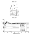
- FIG. 26 there was no thick film portion formed, there was no extremely thin film portion formed, and the difference from the reference value was within ⁇ 4% with respect to the entire width.
- Formation of a thick film portion could be further lessened in the slot curtain coating. Accordingly, it was possible to suppress increase in the thickness of the curtain film by suppressing formation of a boundary layer at the falling portion of the curtain film.
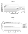
- the fall velocities of the curtain film at heights of 10 mm and 140 mm from the lower edge of the slide die were measured using a fall velocity measuring apparatus (Laser Doppler Noncontact Velocity Meter, Type MODEL 1110A, manufactured by ACT Electronics Corp), and examinations were carried out as to how a boundary layer (such as is shown in FIG. 24 ) in the vicinity of the edge guide changed and how the boundary layer affected the thickness distribution of the curtain film.
- the results are shown in Table 13 and FIGS. 27 and 28 .
- Example B-13 Auxiliary water introduction rate (m/sec) Data on fall velocity Position apart from lower edge of slide die by 10 mm Position apart from lower edge of slide die by 140 mm
- Example B-13 0.4
- the fall velocity of the curtain film was lower than the average fall velocity, far as a position apart from the bottom surface of the concave portion by 2.5 mm.
- the fall velocity of the curtain film was low only in the as immediate vicinity of the edge guide, and was lower than the average fall velocity (-3.2%)
- Example B-1 0.8
- the fall velocity of the curtain film was lower than the average fall velocity, as far as a position apart from the bottom surface of the concave portion by 2.5 mm. There was almost no velocity distribution, with the difference from the average fall velocity being within ⁇ 0.21% with respect to the entire width.
- Example B-21 1.6 The fall velocity of the curtain film was lower than the average fall velocity, as far as a position apart from the bottom surface of the concave portion by 2.5 mm. The fall velocity of the curtain film was higher than the average fall velocity (+5.1%), as far as a position apart from the bottom surface of the concave portion by 15 mm. Example B-18 0.2 The fall velocity of' the curtain film was lower than the average fall velocity, as far as a position apart from the bottom surface of the concave portion by 5 mm A boundary layer was formed, and the fall velocity of the curtain film was lower than the average fall velocity (-9.5%), in the immediate vicinity of the edge guide. Thus, there was a clear velocity distribution.
- Examples B1, B-13 and B-21 were superior to Example B-18 in that a velocity distribution of the curtain film (formed as the coating liquid flowed down the slide portion of the slide die) was removed as the curtain film fell and thus it was possible to suppress formation of a thick film portion.
- a curtain coating apparatus and a curtain coating method according to the present invention can, for example, be suitably used for producing silver halide photographic sensitized materials, magnetic recording materials, pressure-sensitive/thermosensitive recording papers, art papers, coated papers, inkjet recording sheets and so forth.
Landscapes
- Chemical & Material Sciences (AREA)
- Engineering & Computer Science (AREA)
- Materials Engineering (AREA)
- Physics & Mathematics (AREA)
- General Physics & Mathematics (AREA)
- Coating Apparatus (AREA)
- Application Of Or Painting With Fluid Materials (AREA)
Applications Claiming Priority (2)
| Application Number | Priority Date | Filing Date | Title |
|---|---|---|---|
| JP2009207247 | 2009-09-08 | ||
| JP2010178445A JP5720139B2 (ja) | 2010-08-09 | 2010-08-09 | カーテン塗布装置及びカーテン塗布方法 |
Publications (2)
| Publication Number | Publication Date |
|---|---|
| EP2292336A1 true EP2292336A1 (de) | 2011-03-09 |
| EP2292336B1 EP2292336B1 (de) | 2014-08-13 |
Family
ID=42797293
Family Applications (1)
| Application Number | Title | Priority Date | Filing Date |
|---|---|---|---|
| EP10175603.9A Not-in-force EP2292336B1 (de) | 2009-09-08 | 2010-09-07 | Vorhangbeschichter und Verfahren zur Vorhangbeschichtung |
Country Status (3)
| Country | Link |
|---|---|
| US (1) | US8881674B2 (de) |
| EP (1) | EP2292336B1 (de) |
| CN (1) | CN102009025B (de) |
Cited By (1)
| Publication number | Priority date | Publication date | Assignee | Title |
|---|---|---|---|---|
| EP2952264A1 (de) * | 2014-06-05 | 2015-12-09 | Valmet Technologies, Inc. | Vorhangbeschichtungsvorrichtung |
Families Citing this family (6)
| Publication number | Priority date | Publication date | Assignee | Title |
|---|---|---|---|---|
| JP5938980B2 (ja) | 2011-03-31 | 2016-06-22 | 株式会社リコー | カーテン塗布方法及びカーテン塗布装置 |
| US9333524B2 (en) * | 2013-03-15 | 2016-05-10 | Ricoh Company, Ltd. | Slot curtain coating apparatus and slot curtain coating method |
| JP5858247B2 (ja) * | 2013-09-30 | 2016-02-10 | 株式会社村田製作所 | 塗工装置 |
| JP6669498B2 (ja) | 2013-10-25 | 2020-03-18 | 日本板硝子株式会社 | ガラス板の製造方法及びガラス板 |
| CN108672223B (zh) * | 2018-07-16 | 2024-08-13 | 黎元新能源科技(无锡)有限公司 | 一种狭缝型挤压式涂布设备及其基底平台 |
| JP2021154195A (ja) * | 2020-03-26 | 2021-10-07 | ノードソン コーポレーションNordson Corporation | ノズル、接着剤塗布ヘッド、接着剤塗布装置及びおむつ製造方法 |
Citations (12)
| Publication number | Priority date | Publication date | Assignee | Title |
|---|---|---|---|---|
| JPS4935447B1 (de) | 1968-06-03 | 1974-09-21 | ||
| US4479987A (en) * | 1983-01-04 | 1984-10-30 | Agfa-Gevaert Aktiengesellschaft | Process and an apparatus for stabilizing free-falling liquid curtains |
| JPH01199668A (ja) | 1988-02-01 | 1989-08-11 | Fuji Photo Film Co Ltd | 塗布装置 |
| JPH08192087A (ja) * | 1995-01-19 | 1996-07-30 | Ricoh Co Ltd | 塗工装置 |
| JP2630512B2 (ja) | 1991-06-03 | 1997-07-16 | 富士写真フイルム株式会社 | 塗布方法 |
| JPH09253552A (ja) | 1996-03-21 | 1997-09-30 | Konica Corp | カーテン塗布装置 |
| JP2001046939A (ja) | 1999-08-11 | 2001-02-20 | Mitsubishi Paper Mills Ltd | 塗布装置および塗布方法 |
| US20040047999A1 (en) * | 2002-09-10 | 2004-03-11 | Ilford Imaging, Switzerland Gmbh. | Method and device for coating a moving web |
| US20050011439A1 (en) * | 2001-12-13 | 2005-01-20 | Markus Gueggi | Method and apparatus for curtain coating |
| US7081163B2 (en) | 2001-04-09 | 2006-07-25 | Bachofen + Meier Ag Maschinenfabrik | Edge-control system for curtain coater |
| US20070137563A1 (en) * | 2004-04-06 | 2007-06-21 | Peter Schweizer | Curtain coater and curtain coating method |
| WO2008000507A1 (de) | 2006-06-30 | 2008-01-03 | Polytype Converting S.A. | Vorhangbeschichter mit poröser vorhangführungsstruktur, vorhangführungsstruktur für einen vorhangbeschichter und verfahren zur herstellung der vorhangführungsstruktur |
Family Cites Families (7)
| Publication number | Priority date | Publication date | Assignee | Title |
|---|---|---|---|---|
| BR9203828A (pt) * | 1991-10-11 | 1993-06-15 | Eastman Kodak Co | Aparelhagem e processo para recobrir por cortina um suporte movente,com uma ou mais camadas de liquido de recobrimento |
| JPH0935447A (ja) | 1995-07-19 | 1997-02-07 | Kao Corp | テ─プカセット |
| DE69714563T2 (de) * | 1996-12-26 | 2003-04-03 | Konica Corp., Tokio/Tokyo | Verfahren zur Beschichtung eines lichtempfindlichen Materials |
| US6196127B1 (en) | 1997-10-07 | 2001-03-06 | Ricoh Company, Ltd. | Screen process printing method and screen printing machine |
| EP2156898B1 (de) * | 2004-09-09 | 2013-07-31 | Avery Dennison Corporation | Vorhangbeschichtungsvorrichtung |
| JP5169571B2 (ja) | 2008-07-22 | 2013-03-27 | 株式会社リコー | カーテン塗布方法及び装置 |
| JP2011050816A (ja) | 2009-08-31 | 2011-03-17 | Voith Patent Gmbh | カーテンコータのエッジガイド |
-
2010
- 2010-09-07 US US12/876,700 patent/US8881674B2/en not_active Expired - Fee Related
- 2010-09-07 EP EP10175603.9A patent/EP2292336B1/de not_active Not-in-force
- 2010-09-08 CN CN201010277997.7A patent/CN102009025B/zh not_active Expired - Fee Related
Patent Citations (12)
| Publication number | Priority date | Publication date | Assignee | Title |
|---|---|---|---|---|
| JPS4935447B1 (de) | 1968-06-03 | 1974-09-21 | ||
| US4479987A (en) * | 1983-01-04 | 1984-10-30 | Agfa-Gevaert Aktiengesellschaft | Process and an apparatus for stabilizing free-falling liquid curtains |
| JPH01199668A (ja) | 1988-02-01 | 1989-08-11 | Fuji Photo Film Co Ltd | 塗布装置 |
| JP2630512B2 (ja) | 1991-06-03 | 1997-07-16 | 富士写真フイルム株式会社 | 塗布方法 |
| JPH08192087A (ja) * | 1995-01-19 | 1996-07-30 | Ricoh Co Ltd | 塗工装置 |
| JPH09253552A (ja) | 1996-03-21 | 1997-09-30 | Konica Corp | カーテン塗布装置 |
| JP2001046939A (ja) | 1999-08-11 | 2001-02-20 | Mitsubishi Paper Mills Ltd | 塗布装置および塗布方法 |
| US7081163B2 (en) | 2001-04-09 | 2006-07-25 | Bachofen + Meier Ag Maschinenfabrik | Edge-control system for curtain coater |
| US20050011439A1 (en) * | 2001-12-13 | 2005-01-20 | Markus Gueggi | Method and apparatus for curtain coating |
| US20040047999A1 (en) * | 2002-09-10 | 2004-03-11 | Ilford Imaging, Switzerland Gmbh. | Method and device for coating a moving web |
| US20070137563A1 (en) * | 2004-04-06 | 2007-06-21 | Peter Schweizer | Curtain coater and curtain coating method |
| WO2008000507A1 (de) | 2006-06-30 | 2008-01-03 | Polytype Converting S.A. | Vorhangbeschichter mit poröser vorhangführungsstruktur, vorhangführungsstruktur für einen vorhangbeschichter und verfahren zur herstellung der vorhangführungsstruktur |
Non-Patent Citations (3)
| Title |
|---|
| A STUDY OF THE BEHAVIOR OF A THIN SHEET OF MOVING LIQUID J. FLUID MECHANICS, vol. 10, pages 297 - 305 |
| J. VAN HAVENBERGH; H. BUSSMANN; P, JOOS, COLLOID INTERFACE SCI., vol. 101, 1984, pages 462 |
| SARTOR, LUIGI: "Slot Coating: Fluid mechanics and die design", PH.D., 1990 |
Cited By (2)
| Publication number | Priority date | Publication date | Assignee | Title |
|---|---|---|---|---|
| EP2952264A1 (de) * | 2014-06-05 | 2015-12-09 | Valmet Technologies, Inc. | Vorhangbeschichtungsvorrichtung |
| US9675991B2 (en) | 2014-06-05 | 2017-06-13 | Valmet Technologies, Inc. | Curtain coating device |
Also Published As
| Publication number | Publication date |
|---|---|
| CN102009025A (zh) | 2011-04-13 |
| CN102009025B (zh) | 2016-02-10 |
| US20110059254A1 (en) | 2011-03-10 |
| EP2292336B1 (de) | 2014-08-13 |
| US8881674B2 (en) | 2014-11-11 |
Similar Documents
| Publication | Publication Date | Title |
|---|---|---|
| EP2292336B1 (de) | Vorhangbeschichter und Verfahren zur Vorhangbeschichtung | |
| JP2581975B2 (ja) | 塗布装置 | |
| JPH10513399A (ja) | 多層コーティングの方法 | |
| US20080000421A1 (en) | Method and apparatus for applying coating solution with bar | |
| JPS6320069A (ja) | 塗布装置 | |
| EP0452959A2 (de) | Beschichtungsverfahren | |
| US5206056A (en) | Method of application and device for application | |
| JPH05208159A (ja) | カーテンコーティング方法及びその装置 | |
| JP2530202B2 (ja) | 塗布方法 | |
| JP6241333B2 (ja) | スロットカーテン塗布装置及びスロットカーテン塗布方法 | |
| JP5720139B2 (ja) | カーテン塗布装置及びカーテン塗布方法 | |
| US8343588B2 (en) | Slide curtain coating apparatus and slide curtain coating method | |
| EP0563308B1 (de) | Verbesserungen bei oder im zusammenhang mit der beschichtung | |
| JPH01231969A (ja) | 塗布方法 | |
| EP2105210A2 (de) | Beschichtungsverfahren und Beschichtungsvorrichtung | |
| JP5605098B2 (ja) | カーテン塗布装置及びカーテン塗布方法 | |
| CA2404098A1 (en) | Method for forming multilayer release liners and liners formed thereby | |
| AU2001247682A1 (en) | Method for forming multilayer release liners and liners formed thereby | |
| JP4763325B2 (ja) | 塗布液の塗布方法、塗布液の塗布装置、および光学フィルムの製造方法 | |
| JP2006272130A (ja) | 塗布液の塗布方法、塗布液の塗布装置、光学フィルム、および反射防止フィルム | |
| EP2438999B1 (de) | Vorhangbeschichtungsverfahren und Vorhangbeschichtungsvorrichtung | |
| JP2006136840A (ja) | スライド型カーテン塗布装置とスライドホッパー型塗布装置及びそれらを用いた塗布方法 | |
| JPH039788B2 (de) | ||
| JP2004057942A (ja) | 塗布装置及び塗布方法 | |
| JPH10146556A (ja) | エクストルージョン型のコータヘッド |
Legal Events
| Date | Code | Title | Description |
|---|---|---|---|
| PUAI | Public reference made under article 153(3) epc to a published international application that has entered the european phase |
Free format text: ORIGINAL CODE: 0009012 |
|
| 17P | Request for examination filed |
Effective date: 20100907 |
|
| AK | Designated contracting states |
Kind code of ref document: A1 Designated state(s): AL AT BE BG CH CY CZ DE DK EE ES FI FR GB GR HR HU IE IS IT LI LT LU LV MC MK MT NL NO PL PT RO SE SI SK SM TR |
|
| AX | Request for extension of the european patent |
Extension state: BA ME RS |
|
| 17Q | First examination report despatched |
Effective date: 20121025 |
|
| RIC1 | Information provided on ipc code assigned before grant |
Ipc: B05C 5/00 20060101AFI20130927BHEP Ipc: G03C 1/74 20060101ALI20130927BHEP |
|
| GRAP | Despatch of communication of intention to grant a patent |
Free format text: ORIGINAL CODE: EPIDOSNIGR1 |
|
| INTG | Intention to grant announced |
Effective date: 20131216 |
|
| GRAS | Grant fee paid |
Free format text: ORIGINAL CODE: EPIDOSNIGR3 |
|
| GRAA | (expected) grant |
Free format text: ORIGINAL CODE: 0009210 |
|
| AK | Designated contracting states |
Kind code of ref document: B1 Designated state(s): AL AT BE BG CH CY CZ DE DK EE ES FI FR GB GR HR HU IE IS IT LI LT LU LV MC MK MT NL NO PL PT RO SE SI SK SM TR |
|
| RAP1 | Party data changed (applicant data changed or rights of an application transferred) |
Owner name: RICOH COMPANY, LTD. |
|
| REG | Reference to a national code |
Ref country code: GB Ref legal event code: FG4D |
|
| REG | Reference to a national code |
Ref country code: AT Ref legal event code: REF Ref document number: 681871 Country of ref document: AT Kind code of ref document: T Effective date: 20140815 Ref country code: CH Ref legal event code: EP |
|
| REG | Reference to a national code |
Ref country code: IE Ref legal event code: FG4D |
|
| REG | Reference to a national code |
Ref country code: DE Ref legal event code: R096 Ref document number: 602010018164 Country of ref document: DE Effective date: 20140925 |
|
| REG | Reference to a national code |
Ref country code: NL Ref legal event code: VDEP Effective date: 20140813 |
|
| REG | Reference to a national code |
Ref country code: AT Ref legal event code: MK05 Ref document number: 681871 Country of ref document: AT Kind code of ref document: T Effective date: 20140813 |
|
| REG | Reference to a national code |
Ref country code: LT Ref legal event code: MG4D |
|
| PG25 | Lapsed in a contracting state [announced via postgrant information from national office to epo] |
Ref country code: ES Free format text: LAPSE BECAUSE OF FAILURE TO SUBMIT A TRANSLATION OF THE DESCRIPTION OR TO PAY THE FEE WITHIN THE PRESCRIBED TIME-LIMIT Effective date: 20140813 Ref country code: NO Free format text: LAPSE BECAUSE OF FAILURE TO SUBMIT A TRANSLATION OF THE DESCRIPTION OR TO PAY THE FEE WITHIN THE PRESCRIBED TIME-LIMIT Effective date: 20141113 Ref country code: BG Free format text: LAPSE BECAUSE OF FAILURE TO SUBMIT A TRANSLATION OF THE DESCRIPTION OR TO PAY THE FEE WITHIN THE PRESCRIBED TIME-LIMIT Effective date: 20141113 Ref country code: PT Free format text: LAPSE BECAUSE OF FAILURE TO SUBMIT A TRANSLATION OF THE DESCRIPTION OR TO PAY THE FEE WITHIN THE PRESCRIBED TIME-LIMIT Effective date: 20141215 Ref country code: LT Free format text: LAPSE BECAUSE OF FAILURE TO SUBMIT A TRANSLATION OF THE DESCRIPTION OR TO PAY THE FEE WITHIN THE PRESCRIBED TIME-LIMIT Effective date: 20140813 Ref country code: FI Free format text: LAPSE BECAUSE OF FAILURE TO SUBMIT A TRANSLATION OF THE DESCRIPTION OR TO PAY THE FEE WITHIN THE PRESCRIBED TIME-LIMIT Effective date: 20140813 Ref country code: SE Free format text: LAPSE BECAUSE OF FAILURE TO SUBMIT A TRANSLATION OF THE DESCRIPTION OR TO PAY THE FEE WITHIN THE PRESCRIBED TIME-LIMIT Effective date: 20140813 Ref country code: GR Free format text: LAPSE BECAUSE OF FAILURE TO SUBMIT A TRANSLATION OF THE DESCRIPTION OR TO PAY THE FEE WITHIN THE PRESCRIBED TIME-LIMIT Effective date: 20141114 |
|
| PG25 | Lapsed in a contracting state [announced via postgrant information from national office to epo] |
Ref country code: CY Free format text: LAPSE BECAUSE OF FAILURE TO SUBMIT A TRANSLATION OF THE DESCRIPTION OR TO PAY THE FEE WITHIN THE PRESCRIBED TIME-LIMIT Effective date: 20140813 Ref country code: AT Free format text: LAPSE BECAUSE OF FAILURE TO SUBMIT A TRANSLATION OF THE DESCRIPTION OR TO PAY THE FEE WITHIN THE PRESCRIBED TIME-LIMIT Effective date: 20140813 Ref country code: LV Free format text: LAPSE BECAUSE OF FAILURE TO SUBMIT A TRANSLATION OF THE DESCRIPTION OR TO PAY THE FEE WITHIN THE PRESCRIBED TIME-LIMIT Effective date: 20140813 Ref country code: HR Free format text: LAPSE BECAUSE OF FAILURE TO SUBMIT A TRANSLATION OF THE DESCRIPTION OR TO PAY THE FEE WITHIN THE PRESCRIBED TIME-LIMIT Effective date: 20140813 Ref country code: IS Free format text: LAPSE BECAUSE OF FAILURE TO SUBMIT A TRANSLATION OF THE DESCRIPTION OR TO PAY THE FEE WITHIN THE PRESCRIBED TIME-LIMIT Effective date: 20141213 |
|
| PG25 | Lapsed in a contracting state [announced via postgrant information from national office to epo] |
Ref country code: NL Free format text: LAPSE BECAUSE OF FAILURE TO SUBMIT A TRANSLATION OF THE DESCRIPTION OR TO PAY THE FEE WITHIN THE PRESCRIBED TIME-LIMIT Effective date: 20140813 |
|
| PG25 | Lapsed in a contracting state [announced via postgrant information from national office to epo] |
Ref country code: EE Free format text: LAPSE BECAUSE OF FAILURE TO SUBMIT A TRANSLATION OF THE DESCRIPTION OR TO PAY THE FEE WITHIN THE PRESCRIBED TIME-LIMIT Effective date: 20140813 Ref country code: CZ Free format text: LAPSE BECAUSE OF FAILURE TO SUBMIT A TRANSLATION OF THE DESCRIPTION OR TO PAY THE FEE WITHIN THE PRESCRIBED TIME-LIMIT Effective date: 20140813 Ref country code: SK Free format text: LAPSE BECAUSE OF FAILURE TO SUBMIT A TRANSLATION OF THE DESCRIPTION OR TO PAY THE FEE WITHIN THE PRESCRIBED TIME-LIMIT Effective date: 20140813 Ref country code: RO Free format text: LAPSE BECAUSE OF FAILURE TO SUBMIT A TRANSLATION OF THE DESCRIPTION OR TO PAY THE FEE WITHIN THE PRESCRIBED TIME-LIMIT Effective date: 20140813 Ref country code: DK Free format text: LAPSE BECAUSE OF FAILURE TO SUBMIT A TRANSLATION OF THE DESCRIPTION OR TO PAY THE FEE WITHIN THE PRESCRIBED TIME-LIMIT Effective date: 20140813 Ref country code: IT Free format text: LAPSE BECAUSE OF FAILURE TO SUBMIT A TRANSLATION OF THE DESCRIPTION OR TO PAY THE FEE WITHIN THE PRESCRIBED TIME-LIMIT Effective date: 20140813 |
|
| REG | Reference to a national code |
Ref country code: CH Ref legal event code: PL |
|
| REG | Reference to a national code |
Ref country code: DE Ref legal event code: R097 Ref document number: 602010018164 Country of ref document: DE |
|
| PG25 | Lapsed in a contracting state [announced via postgrant information from national office to epo] |
Ref country code: MC Free format text: LAPSE BECAUSE OF FAILURE TO SUBMIT A TRANSLATION OF THE DESCRIPTION OR TO PAY THE FEE WITHIN THE PRESCRIBED TIME-LIMIT Effective date: 20140813 Ref country code: PL Free format text: LAPSE BECAUSE OF FAILURE TO SUBMIT A TRANSLATION OF THE DESCRIPTION OR TO PAY THE FEE WITHIN THE PRESCRIBED TIME-LIMIT Effective date: 20140813 |
|
| REG | Reference to a national code |
Ref country code: IE Ref legal event code: MM4A |
|
| PLBE | No opposition filed within time limit |
Free format text: ORIGINAL CODE: 0009261 |
|
| STAA | Information on the status of an ep patent application or granted ep patent |
Free format text: STATUS: NO OPPOSITION FILED WITHIN TIME LIMIT |
|
| PG25 | Lapsed in a contracting state [announced via postgrant information from national office to epo] |
Ref country code: BE Free format text: LAPSE BECAUSE OF NON-PAYMENT OF DUE FEES Effective date: 20140930 |
|
| 26N | No opposition filed |
Effective date: 20150515 |
|
| PG25 | Lapsed in a contracting state [announced via postgrant information from national office to epo] |
Ref country code: CH Free format text: LAPSE BECAUSE OF NON-PAYMENT OF DUE FEES Effective date: 20140930 Ref country code: LI Free format text: LAPSE BECAUSE OF NON-PAYMENT OF DUE FEES Effective date: 20140930 |
|
| PG25 | Lapsed in a contracting state [announced via postgrant information from national office to epo] |
Ref country code: IE Free format text: LAPSE BECAUSE OF NON-PAYMENT OF DUE FEES Effective date: 20140907 |
|
| PG25 | Lapsed in a contracting state [announced via postgrant information from national office to epo] |
Ref country code: SI Free format text: LAPSE BECAUSE OF FAILURE TO SUBMIT A TRANSLATION OF THE DESCRIPTION OR TO PAY THE FEE WITHIN THE PRESCRIBED TIME-LIMIT Effective date: 20140813 |
|
| PG25 | Lapsed in a contracting state [announced via postgrant information from national office to epo] |
Ref country code: SM Free format text: LAPSE BECAUSE OF FAILURE TO SUBMIT A TRANSLATION OF THE DESCRIPTION OR TO PAY THE FEE WITHIN THE PRESCRIBED TIME-LIMIT Effective date: 20140813 |
|
| PG25 | Lapsed in a contracting state [announced via postgrant information from national office to epo] |
Ref country code: MT Free format text: LAPSE BECAUSE OF FAILURE TO SUBMIT A TRANSLATION OF THE DESCRIPTION OR TO PAY THE FEE WITHIN THE PRESCRIBED TIME-LIMIT Effective date: 20140813 |
|
| PG25 | Lapsed in a contracting state [announced via postgrant information from national office to epo] |
Ref country code: HU Free format text: LAPSE BECAUSE OF FAILURE TO SUBMIT A TRANSLATION OF THE DESCRIPTION OR TO PAY THE FEE WITHIN THE PRESCRIBED TIME-LIMIT; INVALID AB INITIO Effective date: 20100907 Ref country code: BE Free format text: LAPSE BECAUSE OF FAILURE TO SUBMIT A TRANSLATION OF THE DESCRIPTION OR TO PAY THE FEE WITHIN THE PRESCRIBED TIME-LIMIT Effective date: 20140813 Ref country code: TR Free format text: LAPSE BECAUSE OF FAILURE TO SUBMIT A TRANSLATION OF THE DESCRIPTION OR TO PAY THE FEE WITHIN THE PRESCRIBED TIME-LIMIT Effective date: 20140813 Ref country code: LU Free format text: LAPSE BECAUSE OF NON-PAYMENT OF DUE FEES Effective date: 20140907 |
|
| REG | Reference to a national code |
Ref country code: FR Ref legal event code: PLFP Year of fee payment: 7 |
|
| REG | Reference to a national code |
Ref country code: FR Ref legal event code: PLFP Year of fee payment: 8 |
|
| PG25 | Lapsed in a contracting state [announced via postgrant information from national office to epo] |
Ref country code: MK Free format text: LAPSE BECAUSE OF FAILURE TO SUBMIT A TRANSLATION OF THE DESCRIPTION OR TO PAY THE FEE WITHIN THE PRESCRIBED TIME-LIMIT Effective date: 20140813 |
|
| REG | Reference to a national code |
Ref country code: FR Ref legal event code: PLFP Year of fee payment: 9 |
|
| PG25 | Lapsed in a contracting state [announced via postgrant information from national office to epo] |
Ref country code: AL Free format text: LAPSE BECAUSE OF FAILURE TO SUBMIT A TRANSLATION OF THE DESCRIPTION OR TO PAY THE FEE WITHIN THE PRESCRIBED TIME-LIMIT Effective date: 20140813 |
|
| PGFP | Annual fee paid to national office [announced via postgrant information from national office to epo] |
Ref country code: FR Payment date: 20190927 Year of fee payment: 10 Ref country code: DE Payment date: 20190918 Year of fee payment: 10 |
|
| PGFP | Annual fee paid to national office [announced via postgrant information from national office to epo] |
Ref country code: GB Payment date: 20190925 Year of fee payment: 10 |
|
| REG | Reference to a national code |
Ref country code: DE Ref legal event code: R119 Ref document number: 602010018164 Country of ref document: DE |
|
| GBPC | Gb: european patent ceased through non-payment of renewal fee |
Effective date: 20200907 |
|
| PG25 | Lapsed in a contracting state [announced via postgrant information from national office to epo] |
Ref country code: DE Free format text: LAPSE BECAUSE OF NON-PAYMENT OF DUE FEES Effective date: 20210401 Ref country code: FR Free format text: LAPSE BECAUSE OF NON-PAYMENT OF DUE FEES Effective date: 20200930 |
|
| PG25 | Lapsed in a contracting state [announced via postgrant information from national office to epo] |
Ref country code: GB Free format text: LAPSE BECAUSE OF NON-PAYMENT OF DUE FEES Effective date: 20200907 |