EP2292177B1 - Zahnfleischeinschneidegerät - Google Patents
Zahnfleischeinschneidegerät Download PDFInfo
- Publication number
- EP2292177B1 EP2292177B1 EP10009356A EP10009356A EP2292177B1 EP 2292177 B1 EP2292177 B1 EP 2292177B1 EP 10009356 A EP10009356 A EP 10009356A EP 10009356 A EP10009356 A EP 10009356A EP 2292177 B1 EP2292177 B1 EP 2292177B1
- Authority
- EP
- European Patent Office
- Prior art keywords
- gingiva
- leading end
- incising
- incising device
- cutting blade
- Prior art date
- Legal status (The legal status is an assumption and is not a legal conclusion. Google has not performed a legal analysis and makes no representation as to the accuracy of the status listed.)
- Not-in-force
Links
- 210000004195 gingiva Anatomy 0.000 title claims abstract description 140
- 239000004053 dental implant Substances 0.000 claims abstract description 16
- 230000000994 depressogenic effect Effects 0.000 description 4
- 210000000988 bone and bone Anatomy 0.000 description 3
- 238000000034 method Methods 0.000 description 3
- 230000008878 coupling Effects 0.000 description 2
- 238000010168 coupling process Methods 0.000 description 2
- 238000005859 coupling reaction Methods 0.000 description 2
- 210000000214 mouth Anatomy 0.000 description 2
- 210000001909 alveolar process Anatomy 0.000 description 1
- 238000002591 computed tomography Methods 0.000 description 1
- 238000004826 seaming Methods 0.000 description 1
- 239000007787 solid Substances 0.000 description 1
- 210000001519 tissue Anatomy 0.000 description 1
Images


Classifications
-
- A—HUMAN NECESSITIES
- A61—MEDICAL OR VETERINARY SCIENCE; HYGIENE
- A61C—DENTISTRY; APPARATUS OR METHODS FOR ORAL OR DENTAL HYGIENE
- A61C8/00—Means to be fixed to the jaw-bone for consolidating natural teeth or for fixing dental prostheses thereon; Dental implants; Implanting tools
- A61C8/0089—Implanting tools or instruments
Definitions
- the present invention relates to a gingiva incising device which can easily incise a gingiva particularly at a tongue side and a lip side of an alveolar ridge at a position where a dental implant fixture is embedded at a time of carrying out a dental implant treatment.
- this dental implant treatment there has been executed generally a procedure of incising a gingiva on a surface of the jawbone by a surgical knife, making the jawbone expose by setting the incised gingiva to an expanded state, forming an embedment hole by cutting the jawbone with a drill, embedding the dental implant fixture and thereafter seaming the incised gingiva.
- a rotary type gingiva incising device with gingiva thickness measuring device for incising a gingiva formed on a surface of an alveolar bone
- the rotary type gingiva incising device is provided with a cylinder member which is open at one end portion, is closed at the other end portion by a lid member and is formed in a cylindrical shape, a coupling portion which is attached to the lid member and is provided for coupling to a dental engine capable of rotating the rotary type gingiva incising device with gingiva thickness measuring device, a blade portion which is formed at the open end portion of the cylinder member, and incises the gingiva formed on a surface of an alveolar bone on the basis of a rotation of the cylinder member, and a measuring scale which is formed on an outer periphery of the cylinder member, and is provided for measuring a thickness of the gingiva after incising the gingiva formed on the surface of the alveolar bone or during the incision (refer
- the gingiva is incised by using the rotary type gingiva incising device, it is possible to easily form a hole for inserting the dental implant fixture to the gingiva.
- the rotary type gingiva incising device is only structured such that its blade portion formed on the end portion of the cylinder member is rotated by the dental engine such as a hand piece or the like so as to incise the gingiva, it is hard to incise the gingiva on the jawbone formed as a bank shape.
- the jawbone is formed as a bank shape which is rapidly inclined as a whole toward a tongue side and a lip side, and the gingiva lies so as to cover the jawbone formed as the bank shape. Accordingly, if it is intended to incise the gingiva by the gingiva incising device only structured such that the blade portion is provided on a surface which is vertical to a center axis of the cylinder member at a leading end of the cylinder member, the blade portion can not be inserted into the gingiva any more after the leading end of the cylinder member comes into contact with a surface at a top portion of the bank-shaped jawbone, so that there is a problem that the gingiva on the jawbone at the tongue side and the lip side, which is rapidly inclined so as to get depressed, is left uncut.
- the gingiva incising device for incising the gingiva there is a gingiva incising device which uses push-cutting blades having cross sections in various shapes such as a round shape, a triangular shape, a rectangular shape, an oval shape and the like at a leading end of a tubular member, (refer, for example, to the first aspect of the present invention and paragraph 0013 of Japanese Unexamined Patent Publication No. 8-196549 ).
- the gingiva can be incised by selectively using the push-cutting blades in correspondence to the gingiva to be incised, however, a leading end of the tubular member comes into contact with a surface at the top portion of the jawbone and the push-cutting blade at the leading end of the tubular member can not be inserted to the gingiva any more, only by using the tubular members having the different cross sectional shapes as mentioned above. Therefore, it is impossible to solve the problem that the gingiva on the jawbone at the tongue side and the lip side which is rapidly inclined so as to get depressed largely, is left uncut.
- WO - A - 2004 098 435 describes a gingiva incising device having a main body portion provided with a grip portion at its rear end side and having a cylinder portion at its leading end side, wherein the cylinder portion is longer than a thickness of a gingiva, has approximately the same diameter as a diameter of a dental implant fixture and has a cutting blade portion for incising the gingiva, said cutting blade portion being formed as a protrusion on the leading edge of the cylinder portion.
- the present invention is made by taking the problem mentioned above into consideration, and an object of the present invention is to provide a gingiva incising device which can easily incise a gingiva particularly at a tongue side and a lip side of a jawbone formed as a bank shape.
- a gingiva incising device is structured so as to have
- a main body portion provided with a grip portion at its rear end side and having a cylinder portion at its leading end side, wherein the cylinder portion is longer than a thickness of a gingiva, has approximately the same diameter as a diameter of a dental implant fixture and has a cutting blade portion for incising the gingiva formed on a whole periphery of the leading end of said cylinder portion, wherein said cutting blade portion has a portion which protrudes gradually from a position closest to the grip portion toward a position away from the grip portion.
- the gingiva can be securely incised by deeply inserting, and such is preferable.
- a portion at the position closest to the grip portion of the cutting blade portion is formed in a predetermined length on a leading end periphery of the cylinder portion, the gingiva can be incised while avoiding the jawbone coming to an obstacle by the gradually protruding portion comparatively being made small, and such is preferable.
- the gingiva incising device is hard to come off from the gingiva at a time of inserting the cutting blade portion into the gingiva so as to rotate, the gingiva can be easily incised in an accurate cylindrical shape, and such is preferable.
- reference symbol G denotes a gingiva
- reference symbol J denotes a jawbone
- reference numeral 1 denotes a main body portion of the gingiva incising device in accordance with the present invention.
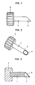
- the main body portion 1 has a cylinder portion 3 as mentioned below at a leading end side thereof, and at least the cylinder portion 3 is hollow, however, the main body portion 1 may be hollow as shown in Fig. 6 or may be solid as shown in Fig. 3 .
- Reference numeral 2 denotes a grip portion provided at a rear end side of the main body portion 1.
- the grip portion 2 may be an independent body from the main body portion 1, or may be integrated with the main body portion 1. Further, a cutting blade portion 4 at a leading end mentioned below is rotated by rotating the grip portion 2 in a state of being gripped by hand or via a rotary tool.
- Reference numeral 3 denotes a cylinder portion which is longer than a thickness of a gingiva G and has approximately the same diameter as a diameter of a dental implant fixture
- reference numeral 4 denotes a cutting blade portion for incising the gingiva, which is formed on a whole periphery of a leading end of the cylinder portion 3.
- the cutting blade portion 4 has a portion which protrudes gradually from a position closest to the grip portion 2 toward a position being away from the grip portion 2.
- the gingiva G can be securely incised by deeply inserting, and such is preferable. Further, in the case that the portion at the position closest to the grip portion 2 in the cutting blade portion 4 is formed in a predetermined length on a leading end periphery of the cylinder portion 3 as shown in Figs. 4 to 6 , the gingiva G can be incised while avoiding the jawbone J coming to an obstacle by the gradually protruding position being made comparatively small, and such is preferable.
- the gingiva incising device is hard to come off from the gingiva G at a time of inserting the cutting blade portion 4 to the gingiva G so as to rotate, the gingiva G can be easily incised in an accurate cylindrical shape, and such is preferable.
- the gingiva incising device in accordance with the present invention, it is possible to use it in combination with a conventional gingiva incising device constructed by a main body portion 1', a grip portion 2' provided at a rear end side of the main body portion 1', and a cylinder portion 3' in which a cutting blade portion is formed on a whole periphery of its leading end which is a surface vertical to a center axis thereof, as shown in Figs. 7 to 9 , or use it singly.
- a conventional gingiva incising device constructed by a main body portion 1', a grip portion 2' provided at a rear end side of the main body portion 1', and a cylinder portion 3' in which a cutting blade portion is formed on a whole periphery of its leading end which is a surface vertical to a center axis thereof, as shown in Figs. 7 to 9 , or use it singly.
- the conventional gingiva incising device is struck into the gingiva G in a state shown in Fig. 10 or is inserted while being rotated until a leading end of the cylinder portion 3' comes into contact with the jawbone J as shown in Fig. 11 . Accordingly, it is possible to form a cylindrical cut in the gingiva G as shown in Fig. 12 , however, there comes a state in which parts of the gingiva G at the tongue side and the lip side are left uncut.
- the left parts of the gingiva G at the tongue side and the lip side are incised by inserting the cutting blade portion 4 at the leading end side of the cylinder portion 3 of the gingiva incising device in accordance with the present invention into the gingiva G in such a manner that the portion protruding gradually toward the position away from the grip portion 2 is positioned at one of the tongue side and the lip side, and rotating it one cycle while gripping the grip portion 2, with respect to the left parts of the gingiva G, as shown in Figs. 13 and 14 .
- the conventional gingiva incising device is used, a cylindrical rough cut is formed in the gingiva G, and the left parts of the gingiva G at the tongue side and the lip side are incised by forming the cut by using the gingiva incising device in accordance with the present invention.
- the portion protruding gradually to the position away from the grip portion 2 in the cutting blade portion 4 is positioned at a gingiva G portion at one of the tongue side and the lip side, and the device is struck in, in such a manner that the cylinder portion 3 of the gingiva incising device in accordance with the present invention can be inserted deeply into the gingiva G, so that a cut is formed in the gingiva G portion by the cutting blade portion 4.
- the portion protruding gradually to the position away from the grip portion 2 in the cutting blade portion 4 is moved to the gingiva G portion at a position on a surface at the top portion side of the bank-shaped jawbone J, by rotating the grip portion 2 in one direction while gripping the grip portion 2, and a cut is formed in the gingiva G at the position on the surface at the top portion side of the jawbone J by the cutting blade portion 4.
- the portion protruding gradually to the position away from the grip portion 2 in the cutting blade portion 4 is positioned at the gingiva G portion at the other of the tongue side and the lip side so as to form a cut by rotating the grip portion 2 in the same direction while gripping the grip portion 2, and a cut is formed in the gingiva G portion at the position on the surface at the top portion side of the jawbone J by further rotating in the same direction. It is possible to incise the gingiva G by only the gingiva incising device in accordance with the present invention, by forming the cuts over the approximately cylindrical whole periphery in the gingiva G as mentioned above.
- the gingiva G is incised by singly using the gingiva incising device in accordance with the present invention as mentioned above, it is necessary to form the cuts in the gingiva G while gripping and rotating the grip portion 2. Accordingly, it is preferable that the leading end of the cylinder portion 3 is formed into such a shape that a portion over at least an approximately one half of the periphery of the leading end of the cutting blade portion 4 can be inserted to the gingiva G, in order to make the gingiva incising device hard to come off from the gingiva G at that time and make it possible to incise the gingiva G in an accurate cylindrical shape.
- a dental template having a bore-tube provided with a guide cylinder, for example, disclosed by the PCT international application No. WO 2003/071972 .
- the guide cylinder has a predetermined inclination at a predetermined position and predetermined standard sizes according to kinds of the dental implant fixture.
- the dental template is produced based on an impression, CT scan data of a jawbone, or the like, taken for every patient.
- the dental template is formed in a mouthpiece shape, and has the bore-tube having the guide cylinder formed at a the position and an inclination according to which the dental implant fixture will be embedded.
- the position for a dental implant fixture can be formed at accurate only by mounting the dental template, inserting a gingiva incising device into the guide cylinder, and incising the gingiva.
Landscapes
- Health & Medical Sciences (AREA)
- Oral & Maxillofacial Surgery (AREA)
- Orthopedic Medicine & Surgery (AREA)
- Dentistry (AREA)
- Epidemiology (AREA)
- Life Sciences & Earth Sciences (AREA)
- Animal Behavior & Ethology (AREA)
- General Health & Medical Sciences (AREA)
- Public Health (AREA)
- Veterinary Medicine (AREA)
- Dental Prosthetics (AREA)
Claims (4)
- Zahnfleischeinschneidevorrichtung mit einem Hauptkörperabschnitt (1), der mit einem Griffabschnitt (2) an seiner hinteren Endseite versehen ist und an seiner führenden Endseite einen Zylinderabschnitt (3) hat, wobei der Zylinderabschnitt (3) länger als eine Dicke eines Zahnfleischs ist, ungefähr den gleichen Durchmesser wie ein Durchmesser einer Zahnimplantatbefestigung hat und einen Schneidklingenabschnitt (4) zum Einschneiden des Zahnfleisch hat, der auf einem gesamten Umfang des führenden Endes des Zylinderabschnitts (3) ausgebildet ist,
dadurch gekennzeichnet, dass
der Schneidklingenabschnitt (4) einen Abschnitt hat, der von einer Position am nächsten zu dem Greifabschnitt (2) in Richtung einer Position entfernt von dem Greifabschnitt (2) fortschreitend vorsteht. - Zahnfleischeinschneidevorrichtung nach Anspruch 1, wobei der Abschnitt, der fortschreitend in die Richtung der Position entfernt von dem Griffabschnitt (2) des Schneidklingenabschnitts (4) vorsteht, über den gesamten Umfang des führenden Endes des Zylinderabschnitts (3) ausgebildet ist.
- Zahnfleischeinschneidevorrichtung nach Anspruch 1, wobei ein Abschnitt an der Position am nächsten zu dem Griffabschnitt (2) des Schneidklingenabschnitts (4) in einer vorgegebenen Länge auf einem Umfang des führenden Endes des Zylinderabschnitts (3) ausgebildet ist.
- Zahnfleischeinschneidevorrichtung nach einem der Ansprüche 1 bis 3, wobei das führende Ende des Zylinderabschnitts (3) zu einer derartigen Form ausgebildet ist, dass ein Abschnitt über wenigstens ungefähr eine Hälfte des Umfangs des führenden Endes des Zylinderabschnitts (3) in das Zahnfleisch eingeführt wird.
Applications Claiming Priority (1)
| Application Number | Priority Date | Filing Date | Title |
|---|---|---|---|
| JP2009207164A JP2011055950A (ja) | 2009-09-08 | 2009-09-08 | 歯肉切除具 |
Publications (2)
| Publication Number | Publication Date |
|---|---|
| EP2292177A1 EP2292177A1 (de) | 2011-03-09 |
| EP2292177B1 true EP2292177B1 (de) | 2012-02-08 |
Family
ID=43234253
Family Applications (1)
| Application Number | Title | Priority Date | Filing Date |
|---|---|---|---|
| EP10009356A Not-in-force EP2292177B1 (de) | 2009-09-08 | 2010-09-08 | Zahnfleischeinschneidegerät |
Country Status (4)
| Country | Link |
|---|---|
| US (1) | US20110059419A1 (de) |
| EP (1) | EP2292177B1 (de) |
| JP (1) | JP2011055950A (de) |
| AT (1) | ATE544418T1 (de) |
Families Citing this family (5)
| Publication number | Priority date | Publication date | Assignee | Title |
|---|---|---|---|---|
| JP6050974B2 (ja) * | 2012-07-02 | 2016-12-21 | 株式会社貝印刃物開発センター | 生体組織切除具 |
| EP3038560B1 (de) | 2013-08-26 | 2018-05-30 | Elos Medtech Timmersdala AB | Zahnärztliche chirurgische vorrichtung |
| CN105491975B (zh) * | 2013-08-26 | 2018-09-28 | 医乐世医疗技术蒂默什达拉公司 | 牙钻系统 |
| KR101375066B1 (ko) * | 2013-11-30 | 2014-03-31 | 정재봉 | 임플란트용 치은 절제 플라이어 |
| JP2016226162A (ja) * | 2015-05-29 | 2016-12-28 | 株式会社豊田中央研究所 | 絶縁型電力変換装置 |
Family Cites Families (21)
| Publication number | Priority date | Publication date | Assignee | Title |
|---|---|---|---|---|
| US1270040A (en) * | 1917-06-29 | 1918-06-18 | Herbert G Miller | Coring-tool. |
| US3515128A (en) * | 1967-12-11 | 1970-06-02 | Bernard F Mcevoy | Skin biopsy punch |
| US3577979A (en) * | 1968-02-06 | 1971-05-11 | Harry Van Der Gaast | Disposable surgical skin punch |
| US3943926A (en) * | 1974-04-10 | 1976-03-16 | Oscar Arvizu Barragan | Wholly disposable dental type syringe |
| US4010543A (en) * | 1975-10-28 | 1977-03-08 | Nusbaum Max J | Hole cutting apparatus |
| US4649918A (en) * | 1980-09-03 | 1987-03-17 | Custom Medical Devices, Inc. | Bone core removing tool |
| US4763552A (en) * | 1987-04-20 | 1988-08-16 | Acco World Corporation | Punch pin configuration |
| JPH05293124A (ja) * | 1992-04-22 | 1993-11-09 | Tdk Corp | 歯科用カッタ−装置 |
| JPH08196549A (ja) * | 1995-01-26 | 1996-08-06 | Nakanishi:Kk | 歯肉切除器および歯肉切除装置 |
| US6223637B1 (en) * | 1995-10-16 | 2001-05-01 | Peter T. Hansen | Catheter side-wall hole cutting method and apparatus |
| US5792163A (en) * | 1996-01-03 | 1998-08-11 | Hitzig; Gary | Linear punch |
| US5827199A (en) * | 1996-06-24 | 1998-10-27 | Alexander; A. Melvin | Biopsy punch apparatus |
| US5788679A (en) * | 1996-06-26 | 1998-08-04 | Gravlee, Jr.; Joseph F. | Phacoemulsification needle |
| IL128261A0 (en) * | 1999-01-27 | 1999-11-30 | Disc O Tech Medical Tech Ltd | Expandable element |
| US5895403A (en) * | 1997-10-17 | 1999-04-20 | Collinsworth; Lonnie Rae | Surgical cutting tool |
| US6685472B2 (en) * | 2001-11-01 | 2004-02-03 | Fred Kastenbaum | Tool for removing soft tissue growth around a dental implant |
| WO2004098435A2 (en) * | 2003-05-02 | 2004-11-18 | Malin, Leo, J. | Dental implant and related methods |
| CN2887260Y (zh) * | 2006-04-19 | 2007-04-11 | 朱春富 | 皮肤打孔器 |
| JP2008104700A (ja) | 2006-10-26 | 2008-05-08 | Michiya Suzuki | 歯肉厚測定器付き回転式歯肉切除器 |
| JP2008142533A (ja) * | 2006-11-16 | 2008-06-26 | Manii Kk | トロカール |
| US20090076463A1 (en) * | 2007-09-17 | 2009-03-19 | Jurg Attinger | Trocar Cannula |
-
2009
- 2009-09-08 JP JP2009207164A patent/JP2011055950A/ja active Pending
-
2010
- 2010-09-08 US US12/877,408 patent/US20110059419A1/en not_active Abandoned
- 2010-09-08 AT AT10009356T patent/ATE544418T1/de active
- 2010-09-08 EP EP10009356A patent/EP2292177B1/de not_active Not-in-force
Also Published As
| Publication number | Publication date |
|---|---|
| EP2292177A1 (de) | 2011-03-09 |
| JP2011055950A (ja) | 2011-03-24 |
| US20110059419A1 (en) | 2011-03-10 |
| ATE544418T1 (de) | 2012-02-15 |
Similar Documents
| Publication | Publication Date | Title |
|---|---|---|
| JP5751817B2 (ja) | ガイド手術用の歯科用ツール | |
| EP2292177B1 (de) | Zahnfleischeinschneidegerät | |
| US9039414B2 (en) | Drill guide pin, shank, cannulated drill bit, and driver for creating a hole in a bone | |
| JP2012010758A (ja) | 穿孔ドリル及び穿孔ドリルシステム | |
| US11576749B2 (en) | Dental surgery method and device | |
| MX2013014101A (es) | Guia de implante dental, juego del mismo, fresa y juego de la misma. | |
| JP5134379B2 (ja) | 医療用切削具 | |
| US20100196849A1 (en) | Flapless dental implant punch | |
| JP5559554B2 (ja) | インプラント手術用歯肉パンチドリル | |
| CN111494034B (zh) | 一种用于前牙区埋伏多生牙拔除的定位导板及其制作方法 | |
| EP3752090B1 (de) | Vorrichtung für die zahnchirurgie | |
| KR200488107Y1 (ko) | 서지컬 가이드를 이용한 플랩리즈 임플란트 수술에 사용되는 반달모양의 티슈펀치 | |
| KR100801510B1 (ko) | 임플란트 시술을 위한 치조골 천공용 천공 부재 및 임플란트 시술을 위한 치조골 천공용 천공 부재 세트 | |
| JP6707734B2 (ja) | インプラント用骨平面形成具 | |
| KR102505011B1 (ko) | 잇몸비절개수술용 공구세트 | |
| US20070088361A1 (en) | Surgical drill for osteotomy | |
| KR20140096231A (ko) | 임플란트용 시술기구 | |
| WO2011016075A1 (en) | Surgical set for cutting the gingiva of a patient during positioning of osseointegrated implants | |
| JP4099813B2 (ja) | 手術用の縫合糸切断(用)メス | |
| JP6891362B2 (ja) | 歯肉切断具 | |
| JP2008104700A (ja) | 歯肉厚測定器付き回転式歯肉切除器 | |
| KR200488108Y1 (ko) | 가이드를 이용한 임플란트 수술 시 사용하는 플랩리스 전용 수동 골막 제거기 | |
| JP3643675B2 (ja) | 抜歯具 | |
| AU2020201283B2 (en) | Dental surgery method and device | |
| KR20120014374A (ko) | 상악동 거상술 시술용 드릴 |
Legal Events
| Date | Code | Title | Description |
|---|---|---|---|
| PUAI | Public reference made under article 153(3) epc to a published international application that has entered the european phase |
Free format text: ORIGINAL CODE: 0009012 |
|
| AK | Designated contracting states |
Kind code of ref document: A1 Designated state(s): AL AT BE BG CH CY CZ DE DK EE ES FI FR GB GR HR HU IE IS IT LI LT LU LV MC MK MT NL NO PL PT RO SE SI SK SM TR |
|
| AX | Request for extension of the european patent |
Extension state: BA ME RS |
|
| 17P | Request for examination filed |
Effective date: 20110622 |
|
| GRAP | Despatch of communication of intention to grant a patent |
Free format text: ORIGINAL CODE: EPIDOSNIGR1 |
|
| RIC1 | Information provided on ipc code assigned before grant |
Ipc: A61C 8/00 20060101AFI20110713BHEP |
|
| GRAS | Grant fee paid |
Free format text: ORIGINAL CODE: EPIDOSNIGR3 |
|
| GRAA | (expected) grant |
Free format text: ORIGINAL CODE: 0009210 |
|
| AK | Designated contracting states |
Kind code of ref document: B1 Designated state(s): AL AT BE BG CH CY CZ DE DK EE ES FI FR GB GR HR HU IE IS IT LI LT LU LV MC MK MT NL NO PL PT RO SE SI SK SM TR |
|
| REG | Reference to a national code |
Ref country code: GB Ref legal event code: FG4D |
|
| REG | Reference to a national code |
Ref country code: AT Ref legal event code: REF Ref document number: 544418 Country of ref document: AT Kind code of ref document: T Effective date: 20120215 Ref country code: CH Ref legal event code: EP |
|
| REG | Reference to a national code |
Ref country code: DE Ref legal event code: R096 Ref document number: 602010000779 Country of ref document: DE Effective date: 20120405 |
|
| REG | Reference to a national code |
Ref country code: SE Ref legal event code: TRGR |
|
| REG | Reference to a national code |
Ref country code: NL Ref legal event code: VDEP Effective date: 20120208 |
|
| LTIE | Lt: invalidation of european patent or patent extension |
Effective date: 20120208 |
|
| PG25 | Lapsed in a contracting state [announced via postgrant information from national office to epo] |
Ref country code: NL Free format text: LAPSE BECAUSE OF FAILURE TO SUBMIT A TRANSLATION OF THE DESCRIPTION OR TO PAY THE FEE WITHIN THE PRESCRIBED TIME-LIMIT Effective date: 20120208 Ref country code: HR Free format text: LAPSE BECAUSE OF FAILURE TO SUBMIT A TRANSLATION OF THE DESCRIPTION OR TO PAY THE FEE WITHIN THE PRESCRIBED TIME-LIMIT Effective date: 20120208 Ref country code: LT Free format text: LAPSE BECAUSE OF FAILURE TO SUBMIT A TRANSLATION OF THE DESCRIPTION OR TO PAY THE FEE WITHIN THE PRESCRIBED TIME-LIMIT Effective date: 20120208 Ref country code: NO Free format text: LAPSE BECAUSE OF FAILURE TO SUBMIT A TRANSLATION OF THE DESCRIPTION OR TO PAY THE FEE WITHIN THE PRESCRIBED TIME-LIMIT Effective date: 20120508 Ref country code: IS Free format text: LAPSE BECAUSE OF FAILURE TO SUBMIT A TRANSLATION OF THE DESCRIPTION OR TO PAY THE FEE WITHIN THE PRESCRIBED TIME-LIMIT Effective date: 20120608 |
|
| PG25 | Lapsed in a contracting state [announced via postgrant information from national office to epo] |
Ref country code: PT Free format text: LAPSE BECAUSE OF FAILURE TO SUBMIT A TRANSLATION OF THE DESCRIPTION OR TO PAY THE FEE WITHIN THE PRESCRIBED TIME-LIMIT Effective date: 20120608 Ref country code: PL Free format text: LAPSE BECAUSE OF FAILURE TO SUBMIT A TRANSLATION OF THE DESCRIPTION OR TO PAY THE FEE WITHIN THE PRESCRIBED TIME-LIMIT Effective date: 20120208 Ref country code: LV Free format text: LAPSE BECAUSE OF FAILURE TO SUBMIT A TRANSLATION OF THE DESCRIPTION OR TO PAY THE FEE WITHIN THE PRESCRIBED TIME-LIMIT Effective date: 20120208 Ref country code: GR Free format text: LAPSE BECAUSE OF FAILURE TO SUBMIT A TRANSLATION OF THE DESCRIPTION OR TO PAY THE FEE WITHIN THE PRESCRIBED TIME-LIMIT Effective date: 20120509 Ref country code: FI Free format text: LAPSE BECAUSE OF FAILURE TO SUBMIT A TRANSLATION OF THE DESCRIPTION OR TO PAY THE FEE WITHIN THE PRESCRIBED TIME-LIMIT Effective date: 20120208 |
|
| REG | Reference to a national code |
Ref country code: AT Ref legal event code: MK05 Ref document number: 544418 Country of ref document: AT Kind code of ref document: T Effective date: 20120208 |
|
| PG25 | Lapsed in a contracting state [announced via postgrant information from national office to epo] |
Ref country code: CY Free format text: LAPSE BECAUSE OF FAILURE TO SUBMIT A TRANSLATION OF THE DESCRIPTION OR TO PAY THE FEE WITHIN THE PRESCRIBED TIME-LIMIT Effective date: 20120208 |
|
| PG25 | Lapsed in a contracting state [announced via postgrant information from national office to epo] |
Ref country code: EE Free format text: LAPSE BECAUSE OF FAILURE TO SUBMIT A TRANSLATION OF THE DESCRIPTION OR TO PAY THE FEE WITHIN THE PRESCRIBED TIME-LIMIT Effective date: 20120208 Ref country code: RO Free format text: LAPSE BECAUSE OF FAILURE TO SUBMIT A TRANSLATION OF THE DESCRIPTION OR TO PAY THE FEE WITHIN THE PRESCRIBED TIME-LIMIT Effective date: 20120208 Ref country code: DK Free format text: LAPSE BECAUSE OF FAILURE TO SUBMIT A TRANSLATION OF THE DESCRIPTION OR TO PAY THE FEE WITHIN THE PRESCRIBED TIME-LIMIT Effective date: 20120208 Ref country code: CZ Free format text: LAPSE BECAUSE OF FAILURE TO SUBMIT A TRANSLATION OF THE DESCRIPTION OR TO PAY THE FEE WITHIN THE PRESCRIBED TIME-LIMIT Effective date: 20120208 Ref country code: SI Free format text: LAPSE BECAUSE OF FAILURE TO SUBMIT A TRANSLATION OF THE DESCRIPTION OR TO PAY THE FEE WITHIN THE PRESCRIBED TIME-LIMIT Effective date: 20120208 |
|
| PG25 | Lapsed in a contracting state [announced via postgrant information from national office to epo] |
Ref country code: SK Free format text: LAPSE BECAUSE OF FAILURE TO SUBMIT A TRANSLATION OF THE DESCRIPTION OR TO PAY THE FEE WITHIN THE PRESCRIBED TIME-LIMIT Effective date: 20120208 Ref country code: IT Free format text: LAPSE BECAUSE OF FAILURE TO SUBMIT A TRANSLATION OF THE DESCRIPTION OR TO PAY THE FEE WITHIN THE PRESCRIBED TIME-LIMIT Effective date: 20120208 |
|
| PLBE | No opposition filed within time limit |
Free format text: ORIGINAL CODE: 0009261 |
|
| STAA | Information on the status of an ep patent application or granted ep patent |
Free format text: STATUS: NO OPPOSITION FILED WITHIN TIME LIMIT |
|
| 26N | No opposition filed |
Effective date: 20121109 |
|
| PG25 | Lapsed in a contracting state [announced via postgrant information from national office to epo] |
Ref country code: AT Free format text: LAPSE BECAUSE OF FAILURE TO SUBMIT A TRANSLATION OF THE DESCRIPTION OR TO PAY THE FEE WITHIN THE PRESCRIBED TIME-LIMIT Effective date: 20120208 |
|
| REG | Reference to a national code |
Ref country code: DE Ref legal event code: R097 Ref document number: 602010000779 Country of ref document: DE Effective date: 20121109 |
|
| PG25 | Lapsed in a contracting state [announced via postgrant information from national office to epo] |
Ref country code: ES Free format text: LAPSE BECAUSE OF FAILURE TO SUBMIT A TRANSLATION OF THE DESCRIPTION OR TO PAY THE FEE WITHIN THE PRESCRIBED TIME-LIMIT Effective date: 20120519 Ref country code: MC Free format text: LAPSE BECAUSE OF NON-PAYMENT OF DUE FEES Effective date: 20120930 |
|
| REG | Reference to a national code |
Ref country code: IE Ref legal event code: MM4A |
|
| PG25 | Lapsed in a contracting state [announced via postgrant information from national office to epo] |
Ref country code: BG Free format text: LAPSE BECAUSE OF FAILURE TO SUBMIT A TRANSLATION OF THE DESCRIPTION OR TO PAY THE FEE WITHIN THE PRESCRIBED TIME-LIMIT Effective date: 20120508 Ref country code: IE Free format text: LAPSE BECAUSE OF NON-PAYMENT OF DUE FEES Effective date: 20120908 |
|
| PGFP | Annual fee paid to national office [announced via postgrant information from national office to epo] |
Ref country code: SE Payment date: 20130917 Year of fee payment: 4 Ref country code: DE Payment date: 20130926 Year of fee payment: 4 |
|
| PG25 | Lapsed in a contracting state [announced via postgrant information from national office to epo] |
Ref country code: MT Free format text: LAPSE BECAUSE OF FAILURE TO SUBMIT A TRANSLATION OF THE DESCRIPTION OR TO PAY THE FEE WITHIN THE PRESCRIBED TIME-LIMIT Effective date: 20120208 Ref country code: AL Free format text: LAPSE BECAUSE OF FAILURE TO SUBMIT A TRANSLATION OF THE DESCRIPTION OR TO PAY THE FEE WITHIN THE PRESCRIBED TIME-LIMIT Effective date: 20120208 |
|
| PGFP | Annual fee paid to national office [announced via postgrant information from national office to epo] |
Ref country code: FR Payment date: 20130724 Year of fee payment: 4 |
|
| PGFP | Annual fee paid to national office [announced via postgrant information from national office to epo] |
Ref country code: BE Payment date: 20130919 Year of fee payment: 4 |
|
| PG25 | Lapsed in a contracting state [announced via postgrant information from national office to epo] |
Ref country code: TR Free format text: LAPSE BECAUSE OF FAILURE TO SUBMIT A TRANSLATION OF THE DESCRIPTION OR TO PAY THE FEE WITHIN THE PRESCRIBED TIME-LIMIT Effective date: 20120208 |
|
| PG25 | Lapsed in a contracting state [announced via postgrant information from national office to epo] |
Ref country code: SM Free format text: LAPSE BECAUSE OF FAILURE TO SUBMIT A TRANSLATION OF THE DESCRIPTION OR TO PAY THE FEE WITHIN THE PRESCRIBED TIME-LIMIT Effective date: 20120208 Ref country code: LU Free format text: LAPSE BECAUSE OF NON-PAYMENT OF DUE FEES Effective date: 20120908 |
|
| PG25 | Lapsed in a contracting state [announced via postgrant information from national office to epo] |
Ref country code: HU Free format text: LAPSE BECAUSE OF FAILURE TO SUBMIT A TRANSLATION OF THE DESCRIPTION OR TO PAY THE FEE WITHIN THE PRESCRIBED TIME-LIMIT Effective date: 20100908 |
|
| REG | Reference to a national code |
Ref country code: DE Ref legal event code: R119 Ref document number: 602010000779 Country of ref document: DE |
|
| REG | Reference to a national code |
Ref country code: CH Ref legal event code: PL |
|
| REG | Reference to a national code |
Ref country code: SE Ref legal event code: EUG |
|
| GBPC | Gb: european patent ceased through non-payment of renewal fee |
Effective date: 20140908 |
|
| PG25 | Lapsed in a contracting state [announced via postgrant information from national office to epo] |
Ref country code: SE Free format text: LAPSE BECAUSE OF NON-PAYMENT OF DUE FEES Effective date: 20140909 |
|
| REG | Reference to a national code |
Ref country code: FR Ref legal event code: ST Effective date: 20150529 |
|
| PG25 | Lapsed in a contracting state [announced via postgrant information from national office to epo] |
Ref country code: BE Free format text: LAPSE BECAUSE OF NON-PAYMENT OF DUE FEES Effective date: 20140930 |
|
| PG25 | Lapsed in a contracting state [announced via postgrant information from national office to epo] |
Ref country code: DE Free format text: LAPSE BECAUSE OF NON-PAYMENT OF DUE FEES Effective date: 20150401 Ref country code: MK Free format text: LAPSE BECAUSE OF FAILURE TO SUBMIT A TRANSLATION OF THE DESCRIPTION OR TO PAY THE FEE WITHIN THE PRESCRIBED TIME-LIMIT Effective date: 20120208 Ref country code: LI Free format text: LAPSE BECAUSE OF NON-PAYMENT OF DUE FEES Effective date: 20140930 Ref country code: GB Free format text: LAPSE BECAUSE OF NON-PAYMENT OF DUE FEES Effective date: 20140908 Ref country code: CH Free format text: LAPSE BECAUSE OF NON-PAYMENT OF DUE FEES Effective date: 20140930 |
|
| PG25 | Lapsed in a contracting state [announced via postgrant information from national office to epo] |
Ref country code: FR Free format text: LAPSE BECAUSE OF NON-PAYMENT OF DUE FEES Effective date: 20140930 |