EP2291901B1 - Elektrische maschine - Google Patents
Elektrische maschine Download PDFInfo
- Publication number
- EP2291901B1 EP2291901B1 EP09769311.3A EP09769311A EP2291901B1 EP 2291901 B1 EP2291901 B1 EP 2291901B1 EP 09769311 A EP09769311 A EP 09769311A EP 2291901 B1 EP2291901 B1 EP 2291901B1
- Authority
- EP
- European Patent Office
- Prior art keywords
- heat sink
- minus
- plus
- diode
- electric generator
- Prior art date
- Legal status (The legal status is an assumption and is not a legal conclusion. Google has not performed a legal analysis and makes no representation as to the accuracy of the status listed.)
- Active
Links
- 238000001816 cooling Methods 0.000 claims description 41
- 230000001681 protective effect Effects 0.000 claims description 31
- 238000004804 winding Methods 0.000 claims description 23
- 210000000078 claw Anatomy 0.000 claims description 2
- 238000004519 manufacturing process Methods 0.000 claims description 2
- 239000011796 hollow space material Substances 0.000 claims 1
- 239000004020 conductor Substances 0.000 description 7
- XEEYBQQBJWHFJM-UHFFFAOYSA-N Iron Chemical compound [Fe] XEEYBQQBJWHFJM-UHFFFAOYSA-N 0.000 description 2
- 238000009423 ventilation Methods 0.000 description 2
- 239000002131 composite material Substances 0.000 description 1
- 230000000694 effects Effects 0.000 description 1
- 230000007613 environmental effect Effects 0.000 description 1
- 229910052742 iron Inorganic materials 0.000 description 1
- 239000000463 material Substances 0.000 description 1
- 238000005096 rolling process Methods 0.000 description 1
- 125000006850 spacer group Chemical group 0.000 description 1
- 238000009827 uniform distribution Methods 0.000 description 1
Images


Classifications
-
- H—ELECTRICITY
- H02—GENERATION; CONVERSION OR DISTRIBUTION OF ELECTRIC POWER
- H02K—DYNAMO-ELECTRIC MACHINES
- H02K9/00—Arrangements for cooling or ventilating
- H02K9/02—Arrangements for cooling or ventilating by ambient air flowing through the machine
- H02K9/04—Arrangements for cooling or ventilating by ambient air flowing through the machine having means for generating a flow of cooling medium
- H02K9/06—Arrangements for cooling or ventilating by ambient air flowing through the machine having means for generating a flow of cooling medium with fans or impellers driven by the machine shaft
-
- H—ELECTRICITY
- H02—GENERATION; CONVERSION OR DISTRIBUTION OF ELECTRIC POWER
- H02K—DYNAMO-ELECTRIC MACHINES
- H02K11/00—Structural association of dynamo-electric machines with electric components or with devices for shielding, monitoring or protection
- H02K11/04—Structural association of dynamo-electric machines with electric components or with devices for shielding, monitoring or protection for rectification
- H02K11/049—Rectifiers associated with stationary parts, e.g. stator cores
- H02K11/05—Rectifiers associated with casings, enclosures or brackets
-
- H—ELECTRICITY
- H02—GENERATION; CONVERSION OR DISTRIBUTION OF ELECTRIC POWER
- H02K—DYNAMO-ELECTRIC MACHINES
- H02K5/00—Casings; Enclosures; Supports
- H02K5/04—Casings or enclosures characterised by the shape, form or construction thereof
- H02K5/20—Casings or enclosures characterised by the shape, form or construction thereof with channels or ducts for flow of cooling medium
- H02K5/207—Casings or enclosures characterised by the shape, form or construction thereof with channels or ducts for flow of cooling medium with openings in the casing specially adapted for ambient air
Definitions
- WO 02/093717 A1 is an electric machine running known as an alternator.
- a rectifier arrangement is disclosed that has a minus heat sink and a plus heat sink for minus diodes and plus diodes. Between these two heat sinks, a connection plate is arranged, which serves to connect the plus and minus diodes with a stator winding, so that a so-called bridge circuit for the purpose of rectifying an alternating current is disclosed.
- the connection plate is designed such that openings are provided for the passage of cooling air.
- the invention relates to an electric generator with the features of independent claim 1.
- Figures 1 and 2 is a cross section through an electric machine shown in principle shown.
- FIG. 3 is a plan view of a plus heat sink having holes around a plus diode shown.
- FIG. 4a a regulator connection is shown (not the subject of the invention).
- FIG. 5 is a cross-section of a fastening device between the connection plate and the protective cap shown (not the subject of the invention).
- connection plate and a plate with at least one guide sleeve engage with each other (not the subject of the invention).
- FIG. 1 shows a cross section through an electric machine 10 shown in principle, here in the embodiment as a generator or alternator for motor vehicles.
- This electrical machine 10 has, inter alia, a two-part housing 13, which consists of a first bearing plate 13.1 and a second bearing plate 13.2.
- the bearing plate 13.1 and the bearing plate 13.2 take in a so-called stator 16, which consists on the one hand of a substantially annular stator iron 17, and in the radially inwardly directed, axially extending grooves, a stator winding 18 is inserted with a plurality of phase windings.
- This annular stator 16 surrounds with its radially inwardly directed grooved surface a rotor 20 which is formed as a claw-pole rotor.
- the rotor 20 consists, inter alia, of two claw-pole plates 22 and 23, on whose outer circumference in each case axially extending claw-pole fingers 24 and 25 are arranged. Both claw-pole plates 22 and 23 are arranged in the rotor 20 such that their claw-pole fingers 24 and 25, which extend in the axial direction, alternate with one another on the circumference of the rotor 20. This results in magnetically required spaces between the oppositely magnetized claw pole fingers 24 and 25, which are referred to as Klauenpol formatschreib.
- the rotor 20 is rotatably supported in the respective end shields 13.1 and 13.2, respectively, by means of a shaft 27 and one respective rolling bearing 28 located on each side of the rotor.
- the rotor 20 has a total of two axial end faces, on each of which a fan 30 is attached.
- This fan 30 consists essentially of a plate-shaped or disc-shaped portion, emanating from the fan blades in a known manner.
- These fans 30 serve to allow an air exchange between the outside of the electric machine 10 and the interior of the electric machine 10 via openings 40 in the end shields 13.1 and 13.2.
- the openings 40 are provided essentially at the axial ends of the end shields 13.1 and 13.2, via which cooling air is sucked into the interior of the electric machine 10 by means of the fan 30.
- This cooling air is accelerated by the rotation of the fan 30 radially outward, so that they can pass through the cool air-permeable winding overhang 45 therethrough. By this effect, the winding overhang 45 is cooled.
- the cooling air takes after passing through the winding overhang 45 or after flowing around this winding overhang 45 a way to the outside radially, not shown here in this figure 1 openings.
- FIG. 1 on the right side there is a protective cap 47, which protects various components against environmental influences.
- this protective cap 47 covers, for example, a so-called slip ring assembly 49, which serves to supply a field winding 51 with exciter current.
- a heat sink 53 Around this slip ring assembly 49 around a heat sink 53 is arranged, which acts as a positive heat sink here.
- the bearing plate acts 13.2.
- a connection plate 56 is arranged, which serves to connect arranged in the bearing plate 13.2 minus diodes 58 and not shown here in this illustration plus diodes in the heat sink 53 together and thus represent a known bridge circuit.
- FIG. 2 The protective cap 47 has a cylindrical outer edge 70, which is directed to the bearing plate 13.2.
- the protective cap 47 further has a central plateau 73, in the middle of which there is an opening 76.
- the protective cap 47 has in its plateau 73 a plurality of annularly arranged ventilation openings 82. Directly opposite these ventilation openings 82 is located in the interior of the electric machine 10 of the plus heat sink 53.
- In this heat sink 53 are a plurality of positive diodes 85, which are inserted with their diode base 88 in cylindrical openings of the heat sink 53.
- the plus diode 85 protrudes with its end facing the connection plate 56 into an opening 91 of the connection plate 56.
- a diode connection wire 94 is directed to an annular region of the bearing plate 13. 2, in which a plurality of air inlet openings 97 for ventilating the machine 10 are arranged.
- the protective cap 47 has between the cylindrical outer edge 70 and the plateau 73 a lowered annular region 100, which extends over at least part of the circumference, especially over the angular range, starting from an axis of rotation of the rotor 20 over which the positive diodes 85 are arranged.
- annular region 100 In this annular region 100 a plurality of openings 103 are arranged over its length, which allow the entry of cooling air.
- minus heatsink 106 which is part of the bearing plate 13.2 here are also in FIG. 2 not shown openings exist in which the minus diodes 58 are inserted.
- an electric machine preferably electric generator, shown with a stator and a rotor, wherein the stator has a stator winding (a plurality of phase windings), which is electrically connected to a rectifier 105, wherein the rectifier connected by a bridge circuit plus and minus diodes wherein the plus diodes are connected to a positive heat sink and the negative diodes are connected to a negative heat sink (alternatively soldered to a heat sink not perforated there) and the rectifier is covered by a protective cap 47 having cooling air openings, the protective cap 47 having at least one opening, which is arranged axially above the negative diode and the minus heat sink.
- the positive heat sink 53 is thus arranged axially above an air inlet opening 97 in the bearing plate 13.2.
- the opening 103 is at least extends such that in the axial direction at least a surface portion of a diode surface with a Length over half a diameter of a negative diode 58 released uninterrupted or covered by the opening 103, sa FIG. 2a ,
- a cavity 109 is arranged, wherein the axially arranged over the negative diode 58 opening 103, the negative diode 58 and the diode terminal wire 94 itself and a radial inner edge 112 of the negative heat sink 106 are arranged in a plane 113.
- An opening 82 in the protective cap 47 axially opposite the positive diode 88 has a greater axial distance to the negative heat sink 106, as the opening 103 in the cap axially directly opposite the negative diode 58th
- connection plate 56 for realizing the rectifier bridge circuit is first arranged after a gap 118. After a further space 121 follows the plus heat sink 53. Between the final cap 47 and the plus heat sink 53 is a third gap 124th
- the lowered annular region 100 is approximately at the level of the plus heat sink 53.
- a narrow gap 127 between the plus heat sink 53 and the ring portion 100 is a narrow gap 127. This leads to a throttling of the sucked cooling air such that an overly unfavorable splitting of the cooling air flow is avoided.
- This arrangement causes the cooling air flow, which is sucked through the openings 103, flows substantially between the terminal plate 56 and the negative heat sink 106 and thus the minus diodes 58 effectively cools, because a preheating by cooling of plus diodes 88 does not occur.
- connection plate 56 and the positive heat sink 53 are smaller than the distance between the minus heat sink 106 and the connection plate 56. Further, the outer diameter of the connection plate 56 is approximately equal to or equal to an arcuate outer edge 107 between mounting eyelets 108 for screws 110 of Plus heat sink 53.
- the air inlet openings 97 are separated by webs 128, which are arranged obliquely to the axis of the electric machine.
- the minus heat sink 106 and the plus heat sink 53 overlap in the region of the outer circumference of the plus heat sink 53, whereby a radially outer edge of the air inlet opening 97 of the minus heat sink 106 is axially opposite the outer circumference of the plus heat sink 53.
- the minus heat sink 106 further has a radially outer edge 200 with a substantially axis-parallel surface, which is adjacent to an outlet opening 203 in the bearing plate 13.2.
- one of the minus diode 58 nearest plus diode 88 is arranged offset in the circumferential direction, see also FIG. 3 , This figure shows, inter alia, the plus heat sink, which has holes around a plus diode 88 around.
- FIG. 3 shows a plan view of the plus heat sink 53. Under the positive heat sink 53, the connection plate 56 is arranged, of which only the outstanding under the positive heat sink 53 terminal loops 130 can be seen.
- B + bolt 133 where the electrical power is delivered to the electrical system.
- the B + bolt 133 nearest plus diode 88 to about 2 o'clock position is surrounded by only three cooling holes 136. Two of these cooling holes 136 are also used to cool the plus diode 88, which is at the 5 o'clock position.
- This plus diode 88 is surrounded by a total of six cooling air openings 136, four of which serve exclusively to cool this plus diode 88.
- the third plus diode 88 at about 8 o'clock position is surrounded by eight cooling air openings 136, which serve directly to the cooling of this diode.
- the passage cross-section of the cooling air openings 136 is determined taking into account the mathematical uniform distribution of the passage cross-section of the cooling air openings 136 between located at about 2 o'clock position plus diode 88 and the plus diode 88, which is located at 5 o'clock position. As determined, the plus diode 88 located at the 2 o'clock position is cooled only by two cooling air holes. Two cooling holes 136 serve to also the cooling of the plus diode 88, which is at the 5 o'clock position, so that it is cooled on average by four cooling air openings.
- stator has a stator winding (a plurality of phase windings), which is electrically connected to a rectifier, wherein the rectifier has connected by means of a bridge circuit plus and minus diodes wherein the plus diodes are connected to a plus heat sink and the minus diodes are connected (plugged or soldered) to a minus heat sink, with cooling air openings 136 provided to cool the plus diodes 88, with the plus diode 88 closest to a B + bolt measured is cooled at the chargeable cooling cross section of the cooling air openings 136, least by cooling air openings 136 and cooling air passing therethrough.
- a plus diode 88 which is the second closest to the B + bolt measured at the credible cooling cross section of the cooling air openings 136, better than the other plus diode 88 through cooling air openings 136 and passing therethrough Cooling air is cooled.
- FIG. 4a an unclaimed regulator port 140 is shown.
- This regulator connection 140 consists of a loop 143 emerging from the connection plate 56, which is connected in one piece with conductors embedded in the connection plate 56.
- the loop 143 exits from an approximately prismatic port 146 at a higher point, so it lies in a different plane than the Connecting conductors that enable the bridge circuit.
- the connecting piece 146 extends prismatically in the direction of the axis of the rotor 20 and has approximately at the radially inwardly directed and radially outwardly directed side depending on a guide or connecting groove 149, sa Fig. 4b , In each of these parallel guide or connecting grooves 149 engages a snap hook 150 of a ffertitlehalters 153 a.
- This ercardhalter 153 has in addition to a gripping area 156 with the snap hook 150 a deposit area 159, which is a square here receptacle for a loosely inserted threaded plate 162.
- the threaded plate 162 has in its center an internal thread 165 which is adapted to receive a threaded bolt of a fastening and contact screw 170 (FIG. Fig. 3 ) serves.
- the threaded plate 162 In assembled condition ( Fig. 4a ), the threaded plate 162 is arranged with its thread 165 centrally below the loop 143, so that an electrical contact between a conductor of the regulator 180 and the loop 143 is produced by means of the screw 165 engaging in the fastening and contact screw 170.
- the threaded plate 162 is pressed from below to the loop 143, so that the loop 143 is pressed against the head of the regulator 180.
- stator has a stator winding (a plurality of phase windings), which is electrically connected to a rectifier, wherein the rectifier connected by a bridge circuit plus and A terminal plate 56 carries the conductors in it, which serve the representation of the bridge circuit and this connection plate 56 has a regulator port 140 which carries a protruding from a connecting piece 146 loop 143, wherein on two sides of the connecting piece 146 each have a guide or connecting groove 149 is arranged, in each of which a snap hook 150 of a fferWallethalters 153 engages having a deposit area 159 which has a receptacle for a threaded plate 162, wherein an internal thread 165 for receiving a threaded bolt of a fastening and contact screw 170 (FIGS.
- FIG. 5 a cross section through the unclaimed fastening device between the connection plate 56 and the protective cap 47 is shown. From the connection plate 56 extends radially outward a holding tube 183, on whose side facing away from the bearing plate 13.2 side, the protective cap 47 rests with its inside.
- the holding tube 183 has on its outer side a step 186, which is engaged behind by a snap hook 189 of the protective cap 47.
- stator has a stator winding (a plurality of phase windings), which is electrically connected to a rectifier, wherein the rectifier connected by a bridge circuit plus and A terminal plate 56 carries the conductors in it, which serve to represent the bridge circuit, wherein a fastening device between the connection plate 56 and the protective cap 47 is present and extending from the connection plate 56 approximately radially outwardly a holding tube 183, preferably on its side facing away from the bearing plate 13.2 side, the protective cap 47 rests with its inner side, wherein the holding tube 183 has on its outer side a step 186 which is engaged behind by a snap hook 189 of the cap 47.
- stator has a stator winding (a plurality of phase windings), which is electrically connected to a rectifier, wherein the rectifier connected by a bridge circuit plus and
- a terminal plate 56 carries the conductors in it, which serve to represent the bridge circuit, wherein a fastening device between the connection plate 56 and the protective cap 47 is present and
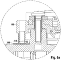
- the plate 200 lies with a surface area 206, sa FIG. 6 , on a flat surface of the bearing plate 13.2.
- the at least one integrally formed on the plate 200 guide sleeve 206 engages in an opening of the bearing plate 13.2 and receives one or more leads 212 of a stator winding 18.
- the connecting wires contact contact elements in the form of connection loops 130.
- From the plate 200 extends radially inward from a surface element 215, from which a web portion 218 projects axially outward.
- This web portion 218 is as in FIG. 6 shown, for example, annular or linear and engages behind the holding tube 183. Radially outside of this web portion 218, the holding tube 183 is supported and prevented so in not yet fixed (Assembly) state the plate 200, which in this way can not easily loose the composite of end plate 13.2 and connecting plate 56.
- stator has a stator winding (a plurality of phase windings), which is electrically connected to a rectifier, wherein the rectifier connected by a bridge circuit plus and A terminal plate 56 carries the conductors in it, which serve the representation of the bridge circuit, wherein the connection plate 56 and a plate 200 with at least one guide sleeve 203 engage with each other, wherein the plate 200 with a surface area 206, on a flat surface of the Bearing plate 13.2 rests and the at least one integrally formed on the plate 200 guide sleeve 206 engages in an opening of the bearing plate 13.2 and one or more leads 212 of a stator winding 18 receives, from the plate 200 radially inward surface element 215 emanates from the one S tegabites 218 projects axially outward, and radially outside of this web portion 218, the support tube 183 is supported on the plate 200
- FIG. 4b shows on the connection plate 56, a spacer element 230, which attaches to a not shown here or similar running distance element on the plus heat sink 53.
- FIG. 5 schematically shows an unclaimed screw cover 240, which is made in one piece with the protective cap 47 made of plastic.
- This screw cover 240 covers the screw head 246 only halfway, so that the here exemplary circular opening 243 is closed only semicircular through the screw cover 240.
- stator has a stator winding (a plurality of phase windings), which is electrically connected to a rectifier, wherein a protective cap 47 made of plastic covers the rectifier, wherein a positive heat sink 53 is fixed by at least one screw 249 on the bearing plate 13.2, the screw 249 is covered by a screw cover 240 which is integral with the protective cap 47 and said screw cover 240, the screw head 246 only partially, preferably half covered in that an opening 243 around the screw 249 is closed only partially, preferably semicircular, through the screw cover 240.
Description
- Aus der Offenlegungsschrift
EP 0 125 834 A2 ist eine elektrische Maschine bekannt, die eine Gleichrichtereinrichtung mit Dioden bekannt, die in einem Plus- und einem Minuskühlkörper angeordnet sind. Der Pluskühlkörper und der Minuskühlkörper sind unmittelbar aufeinander angeordnet. - Aus der Offenbarung der
WO 02/093717 A1 - Die Erfindung berifft einen elektrischen Generator mit den Merkmalen des unabhängigen Patentanspruchs 1.
- In den Figuren 1 und
2 ist ein Querschnitt durch eine prinzipiell dargestellte elektrische Maschine gezeigt. - In
Figur 3 ist in Draufsicht ein Pluskühlkörper, der um eine Plusdiode herum Löcher aufweist, gezeigt. - In
Figur 4a ist ein Regleranschluss gezeigt (nicht Gegenstand der Erfindung). - In den
Figuren 4b und 4c ist ein Schraubkontakthalter gezeigt (nicht Gegenstand der Erfindung). - In
Figur 5 ist ein Querschnitt eine Befestigungsvorrichtung zwischen der Anschlussplatte und der Schutzkappe dargestellt (nicht Gegenstand der Erfindung). - In
Figur 6 ist dargestellt, wie die Anschlussplatte und eine Platte mit zumindest einer Führungshülse ineinander eingreifen (nicht Gegenstand der Erfindung). - In Figur 1 ist ein Querschnitt durch eine prinzipiell dargestellte elektrische Maschine 10, hier in der Ausführung als Generator bzw. Drehstromgenerator für Kraftfahrzeuge, gezeigt. Diese elektrische Maschine 10 weist u. a. ein zweiteiliges Gehäuse 13 auf, das aus einem ersten Lagerschild 13.1 und einem zweiten Lagerschild 13.2 besteht. Das Lagerschild 13.1 und das Lagerschild 13.2 nehmen in sich einen sogenannten Stator 16 auf, der einerseits aus einem im Wesentlichen kreisringförmigen Ständereisen 17 besteht, und in dessen nach radial innen gerichtete, sich axial erstreckende Nuten eine Ständerwicklung 18 mit mehreren Phasenwicklungen eingelegt ist. Dieser ringförmige Stator 16 umgibt mit seiner radial nach innen gerichteten genuteten Oberfläche einen Rotor 20, der als Klauenpolläufer ausgebildet ist. Der Rotor 20 besteht u. a. aus zwei Klauenpolplatinen 22 und 23, an deren Außenumfang jeweils sich in axialer Richtung erstreckende Klauenpolfinger 24 und 25 angeordnet sind. Beide Klauenpolplatinen 22 und 23 sind im Rotor 20 derart angeordnet, dass deren sich in axialer Richtung erstreckende Klauenpolfinger 24 bzw. 25 am Umfang des Rotors 20 einander abwechseln. Es ergeben sich dadurch magnetisch erforderliche Zwischenräume zwischen den gegensinnig magnetisierten Klauenpolfingern 24 und 25, die als Klauenpolzwischenräume bezeichnet werden. Der Rotor 20 ist mittels einer Welle 27 und je einem auf je einer Rotorseite befindlichen Wälzlager 28 in den jeweiligen Lagerschilden 13.1 bzw. 13.2 drehbar gelagert.
- Der Rotor 20 weist insgesamt zwei axiale Stirnflächen auf, an denen jeweils ein Lüfter 30 befestigt ist. Dieser Lüfter 30 besteht im Wesentlichen aus einem plattenförmigen bzw. scheibenförmigen Abschnitt, von dem Lüfterschaufeln in bekannter Weise ausgehen. Diese Lüfter 30 dienen dazu, über Öffnungen 40 in den Lagerschilden 13.1 und 13.2 einen Luftaustausch zwischen der Außenseite der elektrischen Maschine 10 und dem Innenraum der elektrischen Maschine 10 zu ermöglichen. Dazu sind die Öffnungen 40 im Wesentlichen an den axialen Enden der Lagerschilde 13.1 und 13.2 vorgesehen, über die mittels der Lüfter 30 Kühlluft in den Innenraum der elektrischen Maschine 10 eingesaugt wird. Diese Kühlluft wird durch die Rotation der Lüfter 30 nach radial außen beschleunigt, so dass diese durch den kühlluftdurchlässigen Wicklungsüberhang 45 hindurch treten kann. Durch diesen Effekt wird der Wicklungsüberhang 45 gekühlt. Die Kühlluft nimmt nach dem Hindurchtreten durch den Wicklungsüberhang 45 bzw. nach dem Umströmen dieses Wicklungsüberhangs 45 einen Weg nach radial außen, durch hier in dieser Figur 1 nicht dargestellte Öffnungen.
- In Figur 1 auf der rechten Seite befindet sich eine Schutzkappe 47, die verschiedene Bauteile vor Umgebungseinflüssen schützt. So deckt diese Schutzkappe 47 beispielsweise eine sogenannte Schleifringbaugruppe 49 ab, die dazu dient, eine Erregerwicklung 51 mit Erregerstrom zu versorgen. Um diese Schleifringbaugruppe 49 herum ist ein Kühlkörper 53 angeordnet, der hier als Pluskühlkörper wirkt. Als sogenannter Minuskühlkörper wirkt das Lagerschild 13.2. Zwischen dem Lagerschild 13.2 und dem Kühlkörper 53 ist eine Anschlussplatte 56 angeordnet, die dazu dient, im Lagerschild 13.2 angeordnete Minusdioden 58 und hier in dieser Darstellung nicht gezeigte Plusdioden im Kühlkörper 53 miteinander zu verbinden und somit eine an sich bekannte Brückenschaltung darzustellen.
-
Figur 2 : Die Schutzkappe 47 weist einen zylindrischen Außenrand 70 auf, der zum Lagerschild 13.2 gerichtet ist. Die Schutzkappe 47 hat des Weiteren ein zentrales Plateau 73, in dessen Mitte sich eine Öffnung 76 befindet. Durch diese Öffnung ragt ein Schleifringschutz 79. Die Schutzkappe 47 hat in ihrem Plateau 73 mehrere ringförmig angeordnete Belüftungsöffnungen 82. Direkt gegenüber von diesen Belüftungsöffnungen 82 befindet sich im Inneren der elektrischen Maschine 10 der Pluskühlkörper 53. In diesem Kühlkörper 53 sind eine Mehrzahl von Plusdioden 85, die mit Ihrem Diodensockel 88 in zylindrische Öffnungen des Kühlkörpers 53 eingesetzt sind. Die Plusdiode 85 ragt mit ihrem der Anschlussplatte 56 zugewandten Ende in eine Öffnung 91 der Anschlussplatte 56 hinein. Ein Diodenanschlussdraht 94 ist auf einen Ringbereich des Lagerschilds 13.2 gerichtet, in dem mehrere Lufteinlassöffnungen 97 zur Belüftung der Maschine 10 angeordnet sind. - Die Schutzkappe 47 hat zwischen dem zylindrischen Außenrand 70 und dem Plateau 73 einen abgesenkten Ringbereich 100, der sich zumindest über einen Teil des Umfangs, vor allem über den Winkelbereich ausgehend von einer Drehachse des Rotors 20, über den die Plusdioden 85 angeordnet sind, erstreckt. In diesem Ringbereich 100 sind über dessen Länge mehrere Öffnungen 103 angeordnet, die den Eintritt von Kühlluft ermöglichen. Im Minuskühlkörper 106, der hier Teil des Lagerschilds 13.2 ist, sind ebenfalls in
Figur 2 nicht dargestellte Öffnungen vorhanden, in denen die Minusdioden 58 eingesteckt sind. - Zwischen dem im Wesentlichen zylindrischen Außenrand 70 und dem Minuskühlkörper 106 ist ein axialer Abstand 104.
- Es ist somit eine elektrische Maschine, vorzugsweise elektrischer Generator, mit einem Stator und einem Rotor gezeigt, wobei der Stator eine Ständerwicklung (mehrere Phasenwicklungen) aufweist, die mit einem Gleichrichter 105 elektrisch verbunden ist, wobei der Gleichrichter mittels einer Brückenschaltung verbundene Plus- und Minusdioden aufweist, wobei die Plusdioden mit einem Pluskühlkörper und die Minusdioden mit einem Minuskühlkörper verbunden sind (eingesteckt oder alternativ auf einem dort dann nicht gelochten Kühlkörper verlötet) und der Gleichrichter von einer Kühlluftöffnungen aufweisenden Schutzkappe 47 bedeckt ist, wobei die Schutzkappe 47 zumindest eine Öffnung aufweist, die axial über der Minusdiode und dem Minuskühlkörper angeordnet ist. Der Pluskühlkörper 53 ist damit axial über einer Lufteinlassöffnung 97 im Lagerschild 13.2 angeordnet ist.
- Es ist vorgesehen, dass die Öffnung 103 zumindest so erstreckt ist, dass in axialer Richtung zumindest ein Flächenabschnitt einer Diodenoberfläche mit einer Länge über einen halben Durchmesser einer Minusdiode 58 unterbrechungsfrei freigegeben bzw. von der Öffnung 103 überdeckt ist, s. a.
Figur 2a . - Zwischen der Schutzkappe 47 und dem Minuskühlkörper ist ein Hohlraum 109 angeordnet, wobei die axial über der Minusdiode 58 angeordnete Öffnung 103, die Minusdiode 58 bzw. deren Diodenanschlussdraht 94 selbst und ein radialer Innenrand 112 des Minuskühlkörpers 106 in einer Ebene 113 angeordnet sind. Dies führt zu einem Kühlluftstrom 115 ohne Umwege mit wenigen Verlusten. Eine Öffnung 82 in der Schutzkappe 47 axial gegenüber der Plusdiode 88 weist einen größeren axialen Abstand zum Minuskühlkörper 106 auf, als die Öffnung 103 in der Schutzkappe axial direkt gegenüber der Minusdiode 58.
- Zwischen der Schutzkappe 47 und dem Minuskühlkörper 106 ist nach einem Zwischenraum 118 zunächst eine Anschlussplatte 56 zur Verwirklichung der Gleichrichterbrückenschaltung angeordnet. Nach einem weiteren Zwischenraum 121 folgt der Pluskühlkörper 53. Zwischen der abschließenden Schutzkappe 47 und dem Pluskühlkörper 53 ist ein dritter Zwischenraum 124.
- Der abgesenkte Ringbereich 100 ist in etwa auf Höhe des Pluskühlkörpers 53. Aus Toleranz- und damit Fertigungsgründen ist zwischen dem Pluskühlkörper 53 und dem Ringbereich 100 ein schmaler Zwischenraum 127. Dies führt zu einer Drosselung der angesaugten Kühlluft derart, dass eine allzu ungünstige Aufspaltung des Kühlluftstroms vermieden wird. Diese Anordnung führt dazu, dass der Kühlluftstrom, der durch die Öffnungen 103 angesaugt wird, im wesentlichen zwischen der Anschlussplatte 56 und dem Minuskühlkörper 106 strömt und damit die Minusdioden 58 effektiv kühlt, weil eine Vorerwärmung durch Kühlung von Plusdioden 88 nicht erfolgt.
- Ein Abstand zwischen der Anschlussplatte 56 und dem Pluskühlkörper 53 ist kleiner als der Abstand zwischen dem Minuskühlkörper 106 und der Anschlussplatte 56. Des Weiteren ist der Außendurchmesser der Anschlussplatte 56 in etwa so oder gleich groß wie eine bogenförmige Außenkante 107 zwischen Befestigungsösen 108 für Schrauben 110 des Pluskühlkörpers 53.
- Die Lufteinlassöffnungen 97 sind durch Stege 128 getrennt, wobei diese schräg zur Achse der elektrischen Maschine angeordnet sind.
- Der Minuskühlkörper 106 und der Pluskühlkörper 53 überlappen sich im Bereich des Außenumfangs des Pluskühlkörpers 53, wobei dabei ein radial außen liegender Rand der Lufteinlassöffnung 97 des Minuskühlkörpers 106 dem Außenumfangs des Pluskühlkörpers 53 axial gegenüber liegt. Der Minuskühlkörper 106 weist des Weiteren einen radial äußeren Rand 200 mit einer im Wesentlichen achsparallelen Fläche auf, die an eine Auslassöffnung 203 im Lagerschild 13.2 angrenzt.
- Es ist vorgesehen, dass eine der Minusdiode 58 nächstgelegene Plusdiode 88 in Umfangsrichtung versetzt angeordnet ist, s. a.
Figur 3 . Diese Figur zeigt u. a. den Pluskühlkörper, der um eine Plusdiode 88 herum Löcher aufweist. -
Figur 3 zeigt eine Draufsicht auf den Pluskühlkörper 53. Unter dem Pluskühlkörper 53 ist die Anschlussplatte 56 angeordnet, von der nur die unter dem Pluskühlkörper 53 hervorragenden Anschlussschlaufen 130 zu erkennen sind. - Zu erkennen ist auch der sogenannten B+-Bolzen 133, an dem die elektrische Leistung an das Bordnetz abgegeben wird. Die dem B+-Bolzen 133 nächstgelegene Plusdiode 88 auf in etwa 2-Uhr-Position ist nur von drei Kühlungsöffnungen 136 umgeben. Zwei dieser Kühlungsöffnungen 136 dienen zu dem auch der Kühlung der Plusdiode 88, welche sich auf 5-Uhr-Position befindet. Diese Plusdiode 88 ist insgesamt von sechs Kühlluftöffnungen 136 umgeben, von denen vier ausschließlich der Kühlung dieser Plusdiode 88 dienen. Die dritte Plusdiode 88 auf ca. 8-Uhr-Position ist von acht Kühlluftöffnungen 136 umgeben, die unmittelbar der Kühlung dieser Diode dienen.
- Der Durchtrittsquerschnitt der Kühlluftöffnungen 136 ist unter Berücksichtigung der rechnerischen gleichmäßigen Aufteilung des Durchtrittsquerschnitts der Kühlluftöffnungen 136 zwischen der sich auf in etwa 2-Uhr-Position befindenden Plusdiode 88 und der Plusdiode 88, welche sich auf 5-Uhr-Position befindet ermittelt. So ermittelt, ist die sich auf der 2-Uhr-Position befindende Plusdiode 88 nur von zwei Kühlluftöffnungen gekühlt. Zwei Kühlungsöffnungen 136 dienen zu dem auch der Kühlung der Plusdiode 88, welche sich auf 5-Uhr-Position befindet, so dass diese im Mittel durch vier Kühlluftöffnungen gekühlt ist.
- Es ist demnach eine elektrische Maschine, insbesondere elektrischer Generator, mit einem Stator und einem Rotor, offenbart wobei der Stator eine Ständerwicklung (mehrere Phasenwicklungen) aufweist, die mit einem Gleichrichter elektrisch verbunden ist, wobei der Gleichrichter mittels einer Brückenschaltung verbundene Plus- und Minusdioden aufweist, wobei die Plusdioden mit einem Pluskühlkörper und die Minusdioden mit einem Minuskühlkörper verbunden sind (eingesteckt oder verlötet), wobei Kühlluftöffnungen 136 dazu vorgesehen sind, die Plusdioden 88 zu kühlen, wobei die Plusdiode 88, welche einem B+-Bolzen am nächsten gelegen ist, gemessen am anrechenbaren Kühlungsquerschnitt der Kühlluftöffnungen 136, am wenigsten durch Kühlluftöffnungen 136 und dort hindurch tretende Kühlluft gekühlt wird.
- In diesem Zusammenhang ist für eine elektrische Maschine nach dem vorherigen Absatz vorgesehen, dass eine Plusdiode 88, die dem B+-Bolzen am zweitnächsten angeordnet ist, gemessen am anrechenbaren Kühlungsquerschnitt der Kühlluftöffnungen 136, besser als die andere Plusdiode 88 durch Kühlluftöffnungen 136 und dort hindurch tretende Kühlluft gekühlt wird.
- Für den Fall, dass eine dritte Plusdiode 88 vorhanden ist, die vom B+-Bolzen am weitesten entfernt angeordnet ist, ist für diese vorgesehen, gemessen am anrechenbaren Kühlungsquerschnitt der Kühlluftöffnungen 136, dass diese verglichen mit den anderen Plusdioden 88 am meisten Kühlluftöffnungen 136 aufweist. Der Grund hierfür liegt darin, dass die Anschlussplatte 56 im Bereich der dritten Plusdiode 88 verglichen mit den anderen Plusdioden 88 die Kühlluftöffnungen verhältnismäßig großflächig, jedenfalls mehr als bei den anderen beiden Plusdioden 88, abdeckt.
- In
Figur 4a ist ein nicht beanspruchter Regleranschluss 140 gezeigt. Dieser Regleranschluss 140 besteht aus einer aus der Anschlussplatte 56 heraustretenden Schlaufe 143, die einstückig mit in der Anschlussplatte 56 eingebetteten Leitern verbunden ist. Die Schlaufe 143 tritt aus einem in etwa prismatischen Anschlussstutzen 146 an höherer Stelle aus, sie liegt damit in einer anderen Ebene als die Verbindungsleiter, die die Brückenschaltung ermöglichen. Der Anschlussstutzen 146 erstreckt sich prismatisch in Richtung der Achse des Rotors 20 und weist in etwa an der nach radial innen gerichteten und nach radial außen gerichteten Seite je eine Führungs- bzw. Verbindungsnut 149 auf, s. a.Fig. 4b . In diese zueinander parallelen Führungs- bzw. Verbindungsnuten 149 greift je ein Schnapphaken 150 eines Schraubkontakthalters 153 ein. Dieser Schraubkontakthalter 153 weist neben einem Greifbereich 156 mit den Schnapphaken 150 einen Einlagenbereich 159 auf, der eine hier quadratische Aufnahme für ein lose eingelegtes Gewindeplättchen 162 ist. Das Gewindeplättchen 162 weist in seinem Zentrum ein Innengewinde 165 auf, das zur Aufnahme eines Gewindebolzens einer Befestigungs- und Kontaktschraube 170 (Fig. 3 ) dient. Im montierten Zustand (Fig. 4a ) ist das Gewindeplättchen 162 mit seinem Gewinde 165 zentrisch unterhalb der Schlaufe 143 angeordnet, so dass mittels der in das Gewinde 165 eingreifenden Befestigungs- und Kontaktschraube 170 ein elektrischer Kontakt zwischen einem Leiter des Reglers 180 und der Schlaufe 143 hergestellt wird. Das Gewindeplättchen 162 wird dabei von unten an die Schlaufe 143 gedrückt, so dass die Schlaufe 143 gegen den Leiter des Reglers 180 gedrückt wird. - Es ist demnach eine nicht beanspruchte elektrische Maschine, insbesondere elektrischer Generator, mit einem Stator und einem Rotor, offenbart wobei der Stator eine Ständerwicklung (mehrere Phasenwicklungen) aufweist, die mit einem Gleichrichter elektrisch verbunden ist, wobei der Gleichrichter mittels einer Brückenschaltung verbundene Plus- und Minusdioden aufweist, wobei eine Anschlussplatte 56 die Leiter in sich trägt, die der Darstellung der Brückenschaltung dienen und diese Anschlussplatte 56 einen Regleranschluss 140 aufweist, der eine aus einem Anschlussstutzen 146 herausragende Schlaufe 143 trägt, wobei an zwei Seiten des Anschlussstutzens 146 je eine Führungs- bzw. Verbindungsnut 149 angeordnet ist, in die je ein Schnapphaken 150 eines Schraubkontakthalters 153 eingreift, der einen Einlagenbereich 159 aufweist, der eine Aufnahme für ein Gewindeplättchen 162 hat, wobei ein Innengewinde 165 zur Aufnahme eines Gewindebolzens einer Befestigungs- und Kontaktschraube 170 (
Fig. 3 ) dient und im montierten Zustand (Fig. 4a ) das Gewindeplättchen 162 mit seinem Gewinde 165 zentrisch unterhalb der Schlaufe 143 angeordnet ist, so dass mittels der in das Gewinde 165 eingreifenden Befestigungs- und Kontaktschraube 170 ein elektrischer Kontakt zwischen einem Leiter des Reglers 180 und der Schlaufe 143 hergestellt ist. - In
Figur 5 ist ein Querschnitt durch die nicht beanspruchte Befestigungsvorrichtung zwischen der Anschlussplatte 56 und der Schutzkappe 47 dargestellt. Von der Anschlussplatte 56 aus erstreckt sich nach radial außen ein Halterohr 183, auf dessen vom Lagerschild 13.2 abgewandten Seite die Schutzkappe 47 mit ihrer Innenseite aufliegt. Das Halterohr 183 weist auf seiner Außenseite eine Stufe 186 auf, die von einem Schnapphaken 189 der Schutzkappe 47 hintergriffen ist. - Es ist demnach eine nicht beanspruchte elektrische Maschine, insbesondere elektrischer Generator, mit einem Stator und einem Rotor, offenbart wobei der Stator eine Ständerwicklung (mehrere Phasenwicklungen) aufweist, die mit einem Gleichrichter elektrisch verbunden ist, wobei der Gleichrichter mittels einer Brückenschaltung verbundene Plus- und Minusdioden aufweist, wobei eine Anschlussplatte 56 die Leiter in sich trägt, die der Darstellung der Brückenschaltung dienen, wobei eine Befestigungsvorrichtung zwischen der Anschlussplatte 56 und der Schutzkappe 47 vorhanden ist und sich von der Anschlussplatte 56 aus in etwa nach radial außen ein Halterohr 183 erstreckt, vorzugsweise auf dessen vom Lagerschild 13.2 abgewandten Seite die Schutzkappe 47 mit ihrer Innenseite aufliegt, wobei das Halterohr 183 auf seiner Außenseite eine Stufe 186 aufweist, die von einem Schnapphaken 189 der Schutzkappe 47 hintergriffen ist.
- In
Figur 6 ist dargestellt, wie die Anschlussplatte 56 und eine nicht beanspruchte Platte 200 mit zumindest einer Führungshülse 203 ineinander eingreifen. Die Platte 200 liegt mit einem Flächenbereich 206, s. a.Figur 6 , auf einer ebenen Fläche des Lagerschilds 13.2 auf. Die zumindest eine an der Platte 200 einstückig angeformte Führungshülse 206 greift in eine Öffnung des Lagerschilds 13.2 ein und nimmt einen oder mehrere Anschlussdrähte 212 einer Ständerwicklung 18 auf. Die Anschlussdrähte kontaktieren Kontaktelemente in Gestalt von Anschlussschlaufen 130. Von der Platte 200 geht nach radial innen ein Flächenelement 215 aus, von dem ein Stegabschnitt 218 nach axial außen absteht. Dieser Stegabschnitt 218 ist wie inFigur 6 dargestellt bspw. ringförmig oder linienförmig und hintergreift das Halterohr 183. Radial außerhalb dieses Stegabschnitts 218 stützt sich das Halterohr 183 ab und verhindert so im noch nicht fixierten (Montage) Zustand die Platte 200, die auf diese Weise ohne Weiteres nicht lose den Verbund aus Lagerschild 13.2 und Anschlussplatte 56 verlassen kann. - Es ist demnach eine nicht beanspruchte elektrische Maschine, insbesondere elektrischer Generator, mit einem Stator und einem Rotor, offenbart wobei der Stator eine Ständerwicklung (mehrere Phasenwicklungen) aufweist, die mit einem Gleichrichter elektrisch verbunden ist, wobei der Gleichrichter mittels einer Brückenschaltung verbundene Plus- und Minusdioden aufweist, wobei eine Anschlussplatte 56 die Leiter in sich trägt, die der Darstellung der Brückenschaltung dienen, wobei die Anschlussplatte 56 und eine Platte 200 mit zumindest einer Führungshülse 203 ineinander eingreifen, wobei die Platte 200 mit einem Flächenbereich 206, auf einer ebenen Fläche des Lagerschilds 13.2 aufliegt und die zumindest eine an der Platte 200 einstückig angeformte Führungshülse 206 in eine Öffnung des Lagerschilds 13.2 eingreift und einen oder mehrere Anschlussdrähte 212 einer Ständerwicklung 18 aufnimmt, wobei von der Platte 200 nach radial innen ein Flächenelement 215 ausgeht, von dem ein Stegabschnitt 218 nach axial außen absteht, und sich radial außerhalb dieses Stegabschnitts 218 das Halterohr 183 auf der Platte 200 abstützt.
-
Figur 4b zeigt auf der Anschlussplatte 56 ein Distanzelement 230, das sich an einem hier nicht gezeigten gleich oder ähnlich ausgeführten Distanzelement am Pluskühlkörper 53 anlagert. -
Figur 5 zeigt skizzenhaft eine nicht beanspruchte Schraubenabdeckung 240, die einstückig mit der Schutzkappe 47 aus Kunststoff ausgeführt ist. Diese Schraubenabdeckung 240 bedeckt den Schraubenkopf 246 nur zur Hälfte, so dass die hier beispielhaft kreisrunde Öffnung 243 nur halbkreisförmig durch die Schraubenabdeckung 240 geschlossen ist. Dies hat den Vorteil, dass die Schraube 249 nicht gelöst werden kann, wenn die elektrische Maschine 10 an Ort und Stelle im Fahrzeug montiert ist. Angeschlossene Kabel am B+-Bolzen 133 verhindern dies zunächst. Der andere Vorteil besteht darin, dass an dieser Stelle Material eingespart werden kann. - Es ist demnach eine nicht beanspruchte elektrische Maschine, insbesondere elektrischer Generator, mit einem Stator und einem Rotor, offenbart wobei der Stator eine Ständerwicklung (mehrere Phasenwicklungen) aufweist, die mit einem Gleichrichter elektrisch verbunden ist, wobei eine Schutzkappe 47 aus Kunststoff den Gleichrichter abdeckt, wobei ein Pluskühlkörper 53 durch zumindest eine Schraube 249 am Lagerschild 13.2 befestigt ist, wobei die Schraube 249 durch eine Schraubenabdeckung 240, die einstückig mit der Schutzkappe 47 ausgeführt ist abgedeckt ist und wobei diese Schraubenabdeckung 240 den Schraubenkopf 246 nur teilweise, vorzugsweise zur Hälfte, bedeckt, so dass eine Öffnung 243 um die Schraube 249 herum nur teilweise, vorzugsweise halbkreisförmig durch die Schraubenabdeckung 240 geschlossen ist.
Claims (14)
- Elektrischer Generator, mit einem Stator (16) und einem Rotor, wobei der Stator (16) eine Ständerwicklung (18) aufweist, die mit einem Gleichrichter (105) elektrisch verbunden ist,wobei der Gleichrichter (105) mittels einer Brückenschaltung verbundene Plus- und Minusdioden (88, 58) aufweist,wobei die Plusdioden (88) mit einem Pluskühlkörper (53) und die Minusdioden (58) mit einem Minuskühlkörper (106) verbunden sind,wobei der Gleichrichter von einer Kühlluftöffnungen aufweisenden Schutzkappe (47) bedeckt ist,wobei die Schutzkappe (47) zumindest eine Öffnung (103) aufweist, die axial über der Minusdiode (58) und dem Minuskühlkörper (106) angeordnet ist,wobei zwischen der Schutzkappe (47) und dem Minuskühlkörper (106) nach einem Zwischenraum (118) zunächst eine Anschlussplatte (56) zur Verwirklichung der Gleichrichterbrückenschaltung angeordnet ist,wobei nach einem weiteren Zwischenraum (121) der Pluskühlkörper (53) folgt und zwischen der abschließenden Schutzkappe (47) und dem Pluskühlkörper (53) ein dritter Zwischenraum (124) ist,dadurch gekennzeichnet, dassdie Schutzkappe (47) einen abgesenkten Ringbereich (100) aufweist, der in etwa auf axialer Höhe des Pluskühlkörpers (53) ist, wobei aus Toleranz- und Fertigungsgründen zwischen dem Pluskühlkörper (53) und dem Ringbereich (100) ein schmaler Zwischenraum (127) ist, so dass ein Kühlluftstrom (115), der durch die Öffnungen (103) angesaugt wird, im Wesentlichen zwischen der Anschlussplatte (56) und dem Minuskühlkörper (106) strömt und damit die Minusdioden (58) effektiv kühlt, weil eine Vorerwärmung durch Kühlung von Plusdioden (88) nicht erfolgt.
- Elektrischer Generator nach Anspruch 1, dadurch gekennzeichnet, dass die Öffnung (103) in der Schutzkappe (47) axial über der Minusdiode (58) zumindest so erstreckt ist, dass in axialer Richtung zumindest ein Flächenabschnitt einer Diodenoberfläche mit einer Länge über einen halben Durchmesser einer Minusdiode (58) unterbrechungsfrei freigegeben bzw. von der Öffnung (103) überdeckt ist.
- Elektrischer Generator nach Anspruch 1 oder 2, dadurch gekennzeichnet, dass zwischen der Schutzkappe (47) und dem Minuskühlkörper (106) ein Hohlraum (109) angeordnet ist, wobei die Öffnung (103) in der Schutzkappe (47) axial über der Minusdiode (58), ein Diodenanschlussdraht (94) der Minusdiode (94) und ein radialer Innenrand (112) des Minuskühlkörpers (106) in einer Ebene (113) angeordnet sind.
- Elektrischer Generator nach Anspruch 3, dadurch gekennzeichnet, dass eine der Minusdiode (58) nächstgelegene Plusdiode (88) in Umfangsrichtung versetzt angeordnet ist.
- Elektrischer Generator nach einem der vorstehenden Ansprüche, dadurch gekennzeichnet, dass der Pluskühlkörper (53) axial über einer von mehreren Lufteinlassöffnungen (97) im Lagerschild (13.2) angeordnet ist.
- Elektrischer Generator nach Anspruch 5, dadurch gekennzeichnet, dass die Lufteinlassöffnungen (97) durch Stege (128) getrennt sind, wobei diese schräg zur Achse der elektrischen Maschine und nach radial innen zu einer Klauenpolplatine (23) angeordnet sind.
- Elektrischer Generator nach einem der vorstehenden Ansprüche, dadurch gekennzeichnet, dass der Pluskühlkörper (53) um eine Plusdiode (88) herum Kühlluftöffnungen (136) aufweist.
- Elektrischer Generator nach einem der vorstehenden Ansprüche, dadurch gekennzeichnet, dass die Anschlussplatte (56) eine Öffnung (91) aufweist, durch die Kühlluft durchströmen kann, wobei die Öffnung (91) kleiner ist als der äußerste Abstand zweier diagonal gegenüberliegender unmittelbar um die Plusdiode herum angeordneter Kühlluftöffnungen (136).
- Elektrischer Generator nach einem der vorstehenden Ansprüche, dadurch gekennzeichnet, dass ein Abstand zwischen der Anschlussplatte (56) und dem Pluskühlkörper (53) kleiner ist als der Abstand zwischen dem Minuskühlkörper (106) und der Anschlussplatte (56).
- Elektrischer Generator nach einem der vorstehenden Ansprüche, dadurch gekennzeichnet, dass eine Öffnung (82) in der Schutzkappe (47) axial gegenüber der Plusdiode (88) einen größeren axialen Abstand zum Minuskühlkörper (106) aufweist als die Öffnung (103) in der Schutzkappe (47) axial über der Minusdiode (88).
- Elektrischer Generator nach einem der vorstehenden Ansprüche, dadurch gekennzeichnet, dass sich der Minuskühlkörper (106) und der Pluskühlkörper (53) im Bereich des Außenumfangs des Pluskühlkörpers (53) überlappen, wobei dabei ein radial außen liegender Rand einer Lufteinlassöffnung (97) des Minuskühlkörpers (106) dem Pluskühlkörper (53) axial gegenüber liegt.
- Elektrischer Generator nach einem der vorstehenden Ansprüche, dadurch gekennzeichnet, dass die Schutzkappe (47) einen äußeren im Wesentlichen zylindrischen Außenrand (70) aufweist, wobei zwischen dem Außenrand (70) und dem Minuskühlkörper (106) ein axialer Abstand (104) besteht.
- Elektrischer Generator nach einem der vorstehenden Ansprüche, dadurch gekennzeichnet, dass der Minuskühlkörper (106) das Lagerschild (13.2) ist.
- Elektrischer Generator nach Anspruch 13, dadurch gekennzeichnet, dass der Minuskühlkörper (106) einen radial äußeren Rand (200) mit einer im Wesentlichen achsparallelen Fläche aufweist, die an eine Auslassöffnung (203) im Lagerschild (13.2) angrenzt.
Applications Claiming Priority (2)
| Application Number | Priority Date | Filing Date | Title |
|---|---|---|---|
| DE102008002638A DE102008002638A1 (de) | 2008-06-25 | 2008-06-25 | Elektrische Maschine |
| PCT/EP2009/057951 WO2009156463A1 (de) | 2008-06-25 | 2009-06-25 | Elektrische maschine |
Publications (2)
| Publication Number | Publication Date |
|---|---|
| EP2291901A1 EP2291901A1 (de) | 2011-03-09 |
| EP2291901B1 true EP2291901B1 (de) | 2019-06-05 |
Family
ID=41050390
Family Applications (1)
| Application Number | Title | Priority Date | Filing Date |
|---|---|---|---|
| EP09769311.3A Active EP2291901B1 (de) | 2008-06-25 | 2009-06-25 | Elektrische maschine |
Country Status (10)
| Country | Link |
|---|---|
| US (1) | US8531069B2 (de) |
| EP (1) | EP2291901B1 (de) |
| CN (1) | CN102077446B (de) |
| BR (1) | BRPI0914317B1 (de) |
| DE (1) | DE102008002638A1 (de) |
| ES (1) | ES2744385T3 (de) |
| HU (1) | HUE044977T2 (de) |
| MX (1) | MX2010014288A (de) |
| WO (1) | WO2009156463A1 (de) |
| ZA (1) | ZA201102283B (de) |
Families Citing this family (10)
| Publication number | Priority date | Publication date | Assignee | Title |
|---|---|---|---|---|
| JP5575259B2 (ja) * | 2010-10-19 | 2014-08-20 | 三菱電機株式会社 | 車両用交流発電機の整流装置 |
| DE102012022873A1 (de) * | 2012-11-22 | 2014-05-22 | Compact Dynamics Gmbh | Verfahren zum Verlöten von Ständer und Kühler und Ständer mit Lotverbindung zum Ständerträger |
| US20140262155A1 (en) * | 2013-03-14 | 2014-09-18 | Lincoln Global, Inc. | Orbital welding system with cooled drive housing |
| US10811938B2 (en) | 2016-04-07 | 2020-10-20 | Mitsubishi Electric Corporation | Rotating electrical machine |
| DE102016214131A1 (de) * | 2016-08-01 | 2018-02-01 | Robert Bosch Gmbh | Elektrische Maschineneinheit mit Nut zur Aufnahme einer Schutzkappe |
| JP6658624B2 (ja) * | 2017-03-07 | 2020-03-04 | 株式会社デンソー | 回転電機 |
| DE102017214507A1 (de) * | 2017-08-21 | 2019-02-21 | Continental Automotive Gmbh | Mehrteilige Rotorwelle für eine elektrische Maschine |
| US11038394B2 (en) * | 2018-01-25 | 2021-06-15 | Ge Aviation Systems Llc | Generator rotor with coil end-turn retention mechanism |
| RU2688918C1 (ru) * | 2018-08-03 | 2019-05-23 | Федеральное государственное бюджетное образовательное учреждение высшего образования "Оренбургский государственный университет" | Электрическая машина |
| CN111082588A (zh) | 2018-10-19 | 2020-04-28 | 索恩格汽车部件(中国)有限公司 | 电机、用于电机的减振部件和端盖 |
Family Cites Families (16)
| Publication number | Priority date | Publication date | Assignee | Title |
|---|---|---|---|---|
| DE2848410A1 (de) * | 1978-11-08 | 1980-05-29 | Bosch Gmbh Robert | Abdeckhaube fuer elektrische maschinen |
| GB8312963D0 (en) | 1983-05-11 | 1983-06-15 | Lucas Ind Plc | Alternators |
| US4701828A (en) * | 1984-11-07 | 1987-10-20 | Al Weiner | Heat sink assembly |
| DE19705228A1 (de) * | 1997-02-12 | 1998-08-13 | Bosch Gmbh Robert | Elektrische Maschine, vorzugsweise Drehstromgenerator mit Gleichrichter-Baueinheit |
| US5949166A (en) * | 1997-09-25 | 1999-09-07 | Denso Corporation | Rectifying apparatus for an automotive AC generator |
| FR2824966B1 (fr) * | 2001-05-15 | 2003-08-08 | Valeo Equip Electr Moteur | Machine electrique tournante, notamment alternateur pour vehicule automobile |
| DE10111295A1 (de) * | 2001-03-09 | 2002-09-26 | Bosch Gmbh Robert | Anordnung zum Kühlen eines Gleichrichters |
| JP3775235B2 (ja) * | 2001-03-29 | 2006-05-17 | 株式会社デンソー | 車両用交流発電機 |
| EP1388197B1 (de) | 2001-05-15 | 2008-09-10 | Valeo Equipements Electriques Moteur | Drehende elektrische maschine, insbesondere ein fahrzeuggenerator |
| JP3750851B2 (ja) * | 2002-01-18 | 2006-03-01 | 株式会社デンソー | 車両用交流発電機 |
| JP4007229B2 (ja) * | 2002-08-30 | 2007-11-14 | 株式会社デンソー | 車両用交流発電機 |
| US6911750B2 (en) * | 2003-07-03 | 2005-06-28 | Delco Remy International, Inc. | Electronic package for electrical machine |
| JP4497062B2 (ja) * | 2005-08-29 | 2010-07-07 | 株式会社デンソー | 車両用交流発電機 |
| DE102006016239A1 (de) * | 2006-03-31 | 2007-10-04 | Robert Bosch Gmbh | Kühlanordnung für eine Elektromaschine und Elektromaschine mit einer Kühlanordnung |
| JP4340305B2 (ja) * | 2007-06-08 | 2009-10-07 | 三菱電機株式会社 | 車両用交流発電機 |
| DE102007034323A1 (de) * | 2007-07-24 | 2009-01-29 | Robert Bosch Gmbh | Elektrische Maschine |
-
2008
- 2008-06-25 DE DE102008002638A patent/DE102008002638A1/de not_active Withdrawn
-
2009
- 2009-06-25 US US13/001,142 patent/US8531069B2/en active Active
- 2009-06-25 BR BRPI0914317-3A patent/BRPI0914317B1/pt active IP Right Grant
- 2009-06-25 WO PCT/EP2009/057951 patent/WO2009156463A1/de active Application Filing
- 2009-06-25 ES ES09769311T patent/ES2744385T3/es active Active
- 2009-06-25 EP EP09769311.3A patent/EP2291901B1/de active Active
- 2009-06-25 HU HUE09769311 patent/HUE044977T2/hu unknown
- 2009-06-25 CN CN200980124726.3A patent/CN102077446B/zh active Active
- 2009-06-25 MX MX2010014288A patent/MX2010014288A/es active IP Right Grant
-
2011
- 2011-03-28 ZA ZA2011/02283A patent/ZA201102283B/en unknown
Non-Patent Citations (1)
| Title |
|---|
| None * |
Also Published As
| Publication number | Publication date |
|---|---|
| US8531069B2 (en) | 2013-09-10 |
| BRPI0914317B1 (pt) | 2019-04-09 |
| HUE044977T2 (hu) | 2019-11-28 |
| WO2009156463A1 (de) | 2009-12-30 |
| BRPI0914317A2 (pt) | 2015-10-13 |
| CN102077446B (zh) | 2014-03-26 |
| EP2291901A1 (de) | 2011-03-09 |
| US20110215659A1 (en) | 2011-09-08 |
| ES2744385T3 (es) | 2020-02-24 |
| CN102077446A (zh) | 2011-05-25 |
| MX2010014288A (es) | 2011-06-16 |
| DE102008002638A1 (de) | 2009-12-31 |
| ZA201102283B (en) | 2011-12-28 |
Similar Documents
| Publication | Publication Date | Title |
|---|---|---|
| EP2291901B1 (de) | Elektrische maschine | |
| EP3231070B1 (de) | Permanenterregte elektrische maschine | |
| DE602004011600T2 (de) | Elektrischer Motor | |
| EP2380258B2 (de) | Elektrische maschine, insbesondere wechselstromgenerator | |
| DE102011079457B4 (de) | Elektrische Rotationsmaschine | |
| EP2478618B1 (de) | Elektrische maschine | |
| EP1702397B1 (de) | Klauenpolläufer für eine elektrische maschine | |
| EP2478622B1 (de) | Elektrische maschine | |
| WO2014009458A1 (de) | Elektrische maschine | |
| EP2374198B1 (de) | Elektrische maschine mit einem klauenpolrotor | |
| EP2304865B1 (de) | Elektrische maschine | |
| DE10262432B3 (de) | Drehstromgenerator | |
| EP2478621B1 (de) | Kühleinrichtung in einer gleichrichtereinrichtung einer elektrischen maschine | |
| WO2010069715A2 (de) | Maschine mit lagervorrichtung | |
| EP2342799B1 (de) | Elektrische maschine mit einem kontaktelement zur elektrischen verbindung elektrischer bauteile | |
| DE102012212157A1 (de) | Elektrische Maschine | |
| EP2467923A2 (de) | Elektrische maschine | |
| DE102007034323A1 (de) | Elektrische Maschine | |
| WO2008000642A1 (de) | Elektrische maschine, insbesondere drehstromgenerator, sowie kühlungsvorrichtung einer elektrischen maschine | |
| DE102021122045A1 (de) | Vollpolläufer für eine elektrisch erregte Traktionsmaschine, Synchronmaschine und Kraftfahrzeug | |
| DE102017007001A1 (de) | Statorkörper für eine elektrische Rotationsmaschine | |
| WO2014009477A2 (de) | Elektrische maschine | |
| DE102007005171A1 (de) | Elektrische Maschine, insbesondere Generator, mit einem Ständer | |
| EP1950865A2 (de) | Elektrische Maschine mit einem Ständer, sowie Verfahren zur Herstellung einer elektrischen Maschine mit einem Ständer |
Legal Events
| Date | Code | Title | Description |
|---|---|---|---|
| PUAI | Public reference made under article 153(3) epc to a published international application that has entered the european phase |
Free format text: ORIGINAL CODE: 0009012 |
|
| 17P | Request for examination filed |
Effective date: 20110125 |
|
| AK | Designated contracting states |
Kind code of ref document: A1 Designated state(s): AT BE BG CH CY CZ DE DK EE ES FI FR GB GR HR HU IE IS IT LI LT LU LV MC MK MT NL NO PL PT RO SE SI SK TR |
|
| AX | Request for extension of the european patent |
Extension state: AL BA RS |
|
| DAX | Request for extension of the european patent (deleted) | ||
| STAA | Information on the status of an ep patent application or granted ep patent |
Free format text: STATUS: EXAMINATION IS IN PROGRESS |
|
| 17Q | First examination report despatched |
Effective date: 20161201 |
|
| RAP1 | Party data changed (applicant data changed or rights of an application transferred) |
Owner name: SEG AUTOMOTIVE GERMANY GMBH |
|
| GRAP | Despatch of communication of intention to grant a patent |
Free format text: ORIGINAL CODE: EPIDOSNIGR1 |
|
| STAA | Information on the status of an ep patent application or granted ep patent |
Free format text: STATUS: GRANT OF PATENT IS INTENDED |
|
| INTG | Intention to grant announced |
Effective date: 20190102 |
|
| GRAS | Grant fee paid |
Free format text: ORIGINAL CODE: EPIDOSNIGR3 |
|
| GRAA | (expected) grant |
Free format text: ORIGINAL CODE: 0009210 |
|
| STAA | Information on the status of an ep patent application or granted ep patent |
Free format text: STATUS: THE PATENT HAS BEEN GRANTED |
|
| AK | Designated contracting states |
Kind code of ref document: B1 Designated state(s): AT BE BG CH CY CZ DE DK EE ES FI FR GB GR HR HU IE IS IT LI LT LU LV MC MK MT NL NO PL PT RO SE SI SK TR |
|
| REG | Reference to a national code |
Ref country code: GB Ref legal event code: FG4D Free format text: NOT ENGLISH |
|
| REG | Reference to a national code |
Ref country code: CH Ref legal event code: EP |
|
| REG | Reference to a national code |
Ref country code: AT Ref legal event code: REF Ref document number: 1140983 Country of ref document: AT Kind code of ref document: T Effective date: 20190615 |
|
| REG | Reference to a national code |
Ref country code: DE Ref legal event code: R096 Ref document number: 502009015811 Country of ref document: DE |
|
| REG | Reference to a national code |
Ref country code: IE Ref legal event code: FG4D Free format text: LANGUAGE OF EP DOCUMENT: GERMAN |
|
| REG | Reference to a national code |
Ref country code: NL Ref legal event code: MP Effective date: 20190605 |
|
| REG | Reference to a national code |
Ref country code: LT Ref legal event code: MG4D |
|
| PG25 | Lapsed in a contracting state [announced via postgrant information from national office to epo] |
Ref country code: HR Free format text: LAPSE BECAUSE OF FAILURE TO SUBMIT A TRANSLATION OF THE DESCRIPTION OR TO PAY THE FEE WITHIN THE PRESCRIBED TIME-LIMIT Effective date: 20190605 Ref country code: LT Free format text: LAPSE BECAUSE OF FAILURE TO SUBMIT A TRANSLATION OF THE DESCRIPTION OR TO PAY THE FEE WITHIN THE PRESCRIBED TIME-LIMIT Effective date: 20190605 Ref country code: FI Free format text: LAPSE BECAUSE OF FAILURE TO SUBMIT A TRANSLATION OF THE DESCRIPTION OR TO PAY THE FEE WITHIN THE PRESCRIBED TIME-LIMIT Effective date: 20190605 Ref country code: NO Free format text: LAPSE BECAUSE OF FAILURE TO SUBMIT A TRANSLATION OF THE DESCRIPTION OR TO PAY THE FEE WITHIN THE PRESCRIBED TIME-LIMIT Effective date: 20190905 Ref country code: SE Free format text: LAPSE BECAUSE OF FAILURE TO SUBMIT A TRANSLATION OF THE DESCRIPTION OR TO PAY THE FEE WITHIN THE PRESCRIBED TIME-LIMIT Effective date: 20190605 |
|
| REG | Reference to a national code |
Ref country code: HU Ref legal event code: AG4A Ref document number: E044977 Country of ref document: HU |
|
| PG25 | Lapsed in a contracting state [announced via postgrant information from national office to epo] |
Ref country code: LV Free format text: LAPSE BECAUSE OF FAILURE TO SUBMIT A TRANSLATION OF THE DESCRIPTION OR TO PAY THE FEE WITHIN THE PRESCRIBED TIME-LIMIT Effective date: 20190605 Ref country code: GR Free format text: LAPSE BECAUSE OF FAILURE TO SUBMIT A TRANSLATION OF THE DESCRIPTION OR TO PAY THE FEE WITHIN THE PRESCRIBED TIME-LIMIT Effective date: 20190906 Ref country code: BG Free format text: LAPSE BECAUSE OF FAILURE TO SUBMIT A TRANSLATION OF THE DESCRIPTION OR TO PAY THE FEE WITHIN THE PRESCRIBED TIME-LIMIT Effective date: 20190905 |
|
| PG25 | Lapsed in a contracting state [announced via postgrant information from national office to epo] |
Ref country code: CZ Free format text: LAPSE BECAUSE OF FAILURE TO SUBMIT A TRANSLATION OF THE DESCRIPTION OR TO PAY THE FEE WITHIN THE PRESCRIBED TIME-LIMIT Effective date: 20190605 Ref country code: RO Free format text: LAPSE BECAUSE OF FAILURE TO SUBMIT A TRANSLATION OF THE DESCRIPTION OR TO PAY THE FEE WITHIN THE PRESCRIBED TIME-LIMIT Effective date: 20190605 Ref country code: PT Free format text: LAPSE BECAUSE OF FAILURE TO SUBMIT A TRANSLATION OF THE DESCRIPTION OR TO PAY THE FEE WITHIN THE PRESCRIBED TIME-LIMIT Effective date: 20191007 Ref country code: EE Free format text: LAPSE BECAUSE OF FAILURE TO SUBMIT A TRANSLATION OF THE DESCRIPTION OR TO PAY THE FEE WITHIN THE PRESCRIBED TIME-LIMIT Effective date: 20190605 Ref country code: NL Free format text: LAPSE BECAUSE OF FAILURE TO SUBMIT A TRANSLATION OF THE DESCRIPTION OR TO PAY THE FEE WITHIN THE PRESCRIBED TIME-LIMIT Effective date: 20190605 Ref country code: SK Free format text: LAPSE BECAUSE OF FAILURE TO SUBMIT A TRANSLATION OF THE DESCRIPTION OR TO PAY THE FEE WITHIN THE PRESCRIBED TIME-LIMIT Effective date: 20190605 |
|
| REG | Reference to a national code |
Ref country code: CH Ref legal event code: PL |
|
| REG | Reference to a national code |
Ref country code: ES Ref legal event code: FG2A Ref document number: 2744385 Country of ref document: ES Kind code of ref document: T3 Effective date: 20200224 |
|
| PG25 | Lapsed in a contracting state [announced via postgrant information from national office to epo] |
Ref country code: IS Free format text: LAPSE BECAUSE OF FAILURE TO SUBMIT A TRANSLATION OF THE DESCRIPTION OR TO PAY THE FEE WITHIN THE PRESCRIBED TIME-LIMIT Effective date: 20191005 |
|
| REG | Reference to a national code |
Ref country code: DE Ref legal event code: R097 Ref document number: 502009015811 Country of ref document: DE |
|
| REG | Reference to a national code |
Ref country code: BE Ref legal event code: MM Effective date: 20190630 |
|
| PG25 | Lapsed in a contracting state [announced via postgrant information from national office to epo] |
Ref country code: MC Free format text: LAPSE BECAUSE OF FAILURE TO SUBMIT A TRANSLATION OF THE DESCRIPTION OR TO PAY THE FEE WITHIN THE PRESCRIBED TIME-LIMIT Effective date: 20190605 Ref country code: TR Free format text: LAPSE BECAUSE OF FAILURE TO SUBMIT A TRANSLATION OF THE DESCRIPTION OR TO PAY THE FEE WITHIN THE PRESCRIBED TIME-LIMIT Effective date: 20190605 |
|
| PLBE | No opposition filed within time limit |
Free format text: ORIGINAL CODE: 0009261 |
|
| STAA | Information on the status of an ep patent application or granted ep patent |
Free format text: STATUS: NO OPPOSITION FILED WITHIN TIME LIMIT |
|
| PG25 | Lapsed in a contracting state [announced via postgrant information from national office to epo] |
Ref country code: DK Free format text: LAPSE BECAUSE OF FAILURE TO SUBMIT A TRANSLATION OF THE DESCRIPTION OR TO PAY THE FEE WITHIN THE PRESCRIBED TIME-LIMIT Effective date: 20190605 Ref country code: PL Free format text: LAPSE BECAUSE OF FAILURE TO SUBMIT A TRANSLATION OF THE DESCRIPTION OR TO PAY THE FEE WITHIN THE PRESCRIBED TIME-LIMIT Effective date: 20190605 Ref country code: IE Free format text: LAPSE BECAUSE OF NON-PAYMENT OF DUE FEES Effective date: 20190625 |
|
| 26N | No opposition filed |
Effective date: 20200306 |
|
| PG25 | Lapsed in a contracting state [announced via postgrant information from national office to epo] |
Ref country code: BE Free format text: LAPSE BECAUSE OF NON-PAYMENT OF DUE FEES Effective date: 20190630 Ref country code: SI Free format text: LAPSE BECAUSE OF FAILURE TO SUBMIT A TRANSLATION OF THE DESCRIPTION OR TO PAY THE FEE WITHIN THE PRESCRIBED TIME-LIMIT Effective date: 20190605 Ref country code: LU Free format text: LAPSE BECAUSE OF NON-PAYMENT OF DUE FEES Effective date: 20190625 Ref country code: LI Free format text: LAPSE BECAUSE OF NON-PAYMENT OF DUE FEES Effective date: 20190630 Ref country code: CH Free format text: LAPSE BECAUSE OF NON-PAYMENT OF DUE FEES Effective date: 20190630 |
|
| REG | Reference to a national code |
Ref country code: AT Ref legal event code: MM01 Ref document number: 1140983 Country of ref document: AT Kind code of ref document: T Effective date: 20190625 |
|
| GBPC | Gb: european patent ceased through non-payment of renewal fee |
Effective date: 20190905 |
|
| PG25 | Lapsed in a contracting state [announced via postgrant information from national office to epo] |
Ref country code: GB Free format text: LAPSE BECAUSE OF NON-PAYMENT OF DUE FEES Effective date: 20190905 |
|
| PG25 | Lapsed in a contracting state [announced via postgrant information from national office to epo] |
Ref country code: AT Free format text: LAPSE BECAUSE OF NON-PAYMENT OF DUE FEES Effective date: 20190625 |
|
| PG25 | Lapsed in a contracting state [announced via postgrant information from national office to epo] |
Ref country code: CY Free format text: LAPSE BECAUSE OF FAILURE TO SUBMIT A TRANSLATION OF THE DESCRIPTION OR TO PAY THE FEE WITHIN THE PRESCRIBED TIME-LIMIT Effective date: 20190605 |
|
| PG25 | Lapsed in a contracting state [announced via postgrant information from national office to epo] |
Ref country code: MT Free format text: LAPSE BECAUSE OF FAILURE TO SUBMIT A TRANSLATION OF THE DESCRIPTION OR TO PAY THE FEE WITHIN THE PRESCRIBED TIME-LIMIT Effective date: 20190605 |
|
| REG | Reference to a national code |
Ref country code: DE Ref legal event code: R082 Ref document number: 502009015811 Country of ref document: DE Representative=s name: DEHNSGERMANY PARTNERSCHAFT VON PATENTANWAELTEN, DE Ref country code: DE Ref legal event code: R082 Ref document number: 502009015811 Country of ref document: DE Representative=s name: DEHNS GERMANY PARTNERSCHAFT MBB, DE |
|
| PG25 | Lapsed in a contracting state [announced via postgrant information from national office to epo] |
Ref country code: MK Free format text: LAPSE BECAUSE OF FAILURE TO SUBMIT A TRANSLATION OF THE DESCRIPTION OR TO PAY THE FEE WITHIN THE PRESCRIBED TIME-LIMIT Effective date: 20190605 |
|
| PGFP | Annual fee paid to national office [announced via postgrant information from national office to epo] |
Ref country code: FR Payment date: 20230619 Year of fee payment: 15 Ref country code: DE Payment date: 20220728 Year of fee payment: 15 |
|
| PGFP | Annual fee paid to national office [announced via postgrant information from national office to epo] |
Ref country code: HU Payment date: 20230616 Year of fee payment: 15 |
|
| PGFP | Annual fee paid to national office [announced via postgrant information from national office to epo] |
Ref country code: IT Payment date: 20230623 Year of fee payment: 15 Ref country code: ES Payment date: 20230703 Year of fee payment: 15 |