EP2290731A1 - Batteriepack - Google Patents
Batteriepack Download PDFInfo
- Publication number
- EP2290731A1 EP2290731A1 EP20100008860 EP10008860A EP2290731A1 EP 2290731 A1 EP2290731 A1 EP 2290731A1 EP 20100008860 EP20100008860 EP 20100008860 EP 10008860 A EP10008860 A EP 10008860A EP 2290731 A1 EP2290731 A1 EP 2290731A1
- Authority
- EP
- European Patent Office
- Prior art keywords
- battery
- batteries
- holder
- battery pack
- dividing walls
- Prior art date
- Legal status (The legal status is an assumption and is not a legal conclusion. Google has not performed a legal analysis and makes no representation as to the accuracy of the status listed.)
- Granted
Links
- 238000003780 insertion Methods 0.000 claims abstract description 57
- 230000037431 insertion Effects 0.000 claims abstract description 57
- 238000012546 transfer Methods 0.000 claims abstract description 5
- 229920005989 resin Polymers 0.000 claims description 50
- 239000011347 resin Substances 0.000 claims description 50
- 238000004382 potting Methods 0.000 claims description 49
- 229920003023 plastic Polymers 0.000 claims description 9
- 239000004033 plastic Substances 0.000 claims description 9
- 238000005192 partition Methods 0.000 description 11
- 238000007599 discharging Methods 0.000 description 10
- 238000010276 construction Methods 0.000 description 6
- 238000004519 manufacturing process Methods 0.000 description 6
- 239000012530 fluid Substances 0.000 description 4
- 229910052751 metal Inorganic materials 0.000 description 4
- 239000002184 metal Substances 0.000 description 4
- 238000007493 shaping process Methods 0.000 description 4
- 230000002159 abnormal effect Effects 0.000 description 3
- 238000000465 moulding Methods 0.000 description 3
- HBBGRARXTFLTSG-UHFFFAOYSA-N Lithium ion Chemical compound [Li+] HBBGRARXTFLTSG-UHFFFAOYSA-N 0.000 description 2
- 230000015556 catabolic process Effects 0.000 description 2
- 239000004568 cement Substances 0.000 description 2
- 230000008878 coupling Effects 0.000 description 2
- 238000010168 coupling process Methods 0.000 description 2
- 238000005859 coupling reaction Methods 0.000 description 2
- 238000006731 degradation reaction Methods 0.000 description 2
- 238000001514 detection method Methods 0.000 description 2
- WABPQHHGFIMREM-UHFFFAOYSA-N lead(0) Chemical compound [Pb] WABPQHHGFIMREM-UHFFFAOYSA-N 0.000 description 2
- 229910001416 lithium ion Inorganic materials 0.000 description 2
- PXHVJJICTQNCMI-UHFFFAOYSA-N Nickel Chemical compound [Ni] PXHVJJICTQNCMI-UHFFFAOYSA-N 0.000 description 1
- 239000012080 ambient air Substances 0.000 description 1
- OJIJEKBXJYRIBZ-UHFFFAOYSA-N cadmium nickel Chemical compound [Ni].[Cd] OJIJEKBXJYRIBZ-UHFFFAOYSA-N 0.000 description 1
- 238000001816 cooling Methods 0.000 description 1
- 230000001627 detrimental effect Effects 0.000 description 1
- 239000003822 epoxy resin Substances 0.000 description 1
- 238000005304 joining Methods 0.000 description 1
- 238000012423 maintenance Methods 0.000 description 1
- 238000000034 method Methods 0.000 description 1
- 238000012986 modification Methods 0.000 description 1
- 230000004048 modification Effects 0.000 description 1
- 229910000652 nickel hydride Inorganic materials 0.000 description 1
- 229920000647 polyepoxide Polymers 0.000 description 1
- 230000000452 restraining effect Effects 0.000 description 1
- 229920006300 shrink film Polymers 0.000 description 1
- 229920002545 silicone oil Polymers 0.000 description 1
- 229920002050 silicone resin Polymers 0.000 description 1
- 229920002803 thermoplastic polyurethane Polymers 0.000 description 1
Images


Classifications
-
- H—ELECTRICITY
- H01—ELECTRIC ELEMENTS
- H01M—PROCESSES OR MEANS, e.g. BATTERIES, FOR THE DIRECT CONVERSION OF CHEMICAL ENERGY INTO ELECTRICAL ENERGY
- H01M10/00—Secondary cells; Manufacture thereof
- H01M10/60—Heating or cooling; Temperature control
- H01M10/65—Means for temperature control structurally associated with the cells
- H01M10/651—Means for temperature control structurally associated with the cells characterised by parameters specified by a numeric value or mathematical formula, e.g. ratios, sizes or concentrations
- H01M10/652—Means for temperature control structurally associated with the cells characterised by parameters specified by a numeric value or mathematical formula, e.g. ratios, sizes or concentrations characterised by gradients
-
- H—ELECTRICITY
- H01—ELECTRIC ELEMENTS
- H01M—PROCESSES OR MEANS, e.g. BATTERIES, FOR THE DIRECT CONVERSION OF CHEMICAL ENERGY INTO ELECTRICAL ENERGY
- H01M50/00—Constructional details or processes of manufacture of the non-active parts of electrochemical cells other than fuel cells, e.g. hybrid cells
- H01M50/20—Mountings; Secondary casings or frames; Racks, modules or packs; Suspension devices; Shock absorbers; Transport or carrying devices; Holders
- H01M50/262—Mountings; Secondary casings or frames; Racks, modules or packs; Suspension devices; Shock absorbers; Transport or carrying devices; Holders with fastening means, e.g. locks
-
- H—ELECTRICITY
- H01—ELECTRIC ELEMENTS
- H01M—PROCESSES OR MEANS, e.g. BATTERIES, FOR THE DIRECT CONVERSION OF CHEMICAL ENERGY INTO ELECTRICAL ENERGY
- H01M10/00—Secondary cells; Manufacture thereof
- H01M10/60—Heating or cooling; Temperature control
- H01M10/61—Types of temperature control
- H01M10/613—Cooling or keeping cold
-
- H—ELECTRICITY
- H01—ELECTRIC ELEMENTS
- H01M—PROCESSES OR MEANS, e.g. BATTERIES, FOR THE DIRECT CONVERSION OF CHEMICAL ENERGY INTO ELECTRICAL ENERGY
- H01M10/00—Secondary cells; Manufacture thereof
- H01M10/60—Heating or cooling; Temperature control
- H01M10/61—Types of temperature control
- H01M10/617—Types of temperature control for achieving uniformity or desired distribution of temperature
-
- H—ELECTRICITY
- H01—ELECTRIC ELEMENTS
- H01M—PROCESSES OR MEANS, e.g. BATTERIES, FOR THE DIRECT CONVERSION OF CHEMICAL ENERGY INTO ELECTRICAL ENERGY
- H01M10/00—Secondary cells; Manufacture thereof
- H01M10/60—Heating or cooling; Temperature control
- H01M10/64—Heating or cooling; Temperature control characterised by the shape of the cells
- H01M10/643—Cylindrical cells
-
- H—ELECTRICITY
- H01—ELECTRIC ELEMENTS
- H01M—PROCESSES OR MEANS, e.g. BATTERIES, FOR THE DIRECT CONVERSION OF CHEMICAL ENERGY INTO ELECTRICAL ENERGY
- H01M10/00—Secondary cells; Manufacture thereof
- H01M10/60—Heating or cooling; Temperature control
- H01M10/65—Means for temperature control structurally associated with the cells
- H01M10/655—Solid structures for heat exchange or heat conduction
- H01M10/6554—Rods or plates
- H01M10/6555—Rods or plates arranged between the cells
-
- H—ELECTRICITY
- H01—ELECTRIC ELEMENTS
- H01M—PROCESSES OR MEANS, e.g. BATTERIES, FOR THE DIRECT CONVERSION OF CHEMICAL ENERGY INTO ELECTRICAL ENERGY
- H01M50/00—Constructional details or processes of manufacture of the non-active parts of electrochemical cells other than fuel cells, e.g. hybrid cells
- H01M50/20—Mountings; Secondary casings or frames; Racks, modules or packs; Suspension devices; Shock absorbers; Transport or carrying devices; Holders
- H01M50/204—Racks, modules or packs for multiple batteries or multiple cells
- H01M50/207—Racks, modules or packs for multiple batteries or multiple cells characterised by their shape
- H01M50/213—Racks, modules or packs for multiple batteries or multiple cells characterised by their shape adapted for cells having curved cross-section, e.g. round or elliptic
-
- H—ELECTRICITY
- H01—ELECTRIC ELEMENTS
- H01M—PROCESSES OR MEANS, e.g. BATTERIES, FOR THE DIRECT CONVERSION OF CHEMICAL ENERGY INTO ELECTRICAL ENERGY
- H01M50/00—Constructional details or processes of manufacture of the non-active parts of electrochemical cells other than fuel cells, e.g. hybrid cells
- H01M50/20—Mountings; Secondary casings or frames; Racks, modules or packs; Suspension devices; Shock absorbers; Transport or carrying devices; Holders
- H01M50/289—Mountings; Secondary casings or frames; Racks, modules or packs; Suspension devices; Shock absorbers; Transport or carrying devices; Holders characterised by spacing elements or positioning means within frames, racks or packs
-
- H—ELECTRICITY
- H01—ELECTRIC ELEMENTS
- H01M—PROCESSES OR MEANS, e.g. BATTERIES, FOR THE DIRECT CONVERSION OF CHEMICAL ENERGY INTO ELECTRICAL ENERGY
- H01M10/00—Secondary cells; Manufacture thereof
- H01M10/60—Heating or cooling; Temperature control
- H01M10/62—Heating or cooling; Temperature control specially adapted for specific applications
- H01M10/625—Vehicles
-
- H—ELECTRICITY
- H01—ELECTRIC ELEMENTS
- H01M—PROCESSES OR MEANS, e.g. BATTERIES, FOR THE DIRECT CONVERSION OF CHEMICAL ENERGY INTO ELECTRICAL ENERGY
- H01M10/00—Secondary cells; Manufacture thereof
- H01M10/60—Heating or cooling; Temperature control
- H01M10/65—Means for temperature control structurally associated with the cells
- H01M10/655—Solid structures for heat exchange or heat conduction
- H01M10/6551—Surfaces specially adapted for heat dissipation or radiation, e.g. fins or coatings
-
- H—ELECTRICITY
- H01—ELECTRIC ELEMENTS
- H01M—PROCESSES OR MEANS, e.g. BATTERIES, FOR THE DIRECT CONVERSION OF CHEMICAL ENERGY INTO ELECTRICAL ENERGY
- H01M10/00—Secondary cells; Manufacture thereof
- H01M10/60—Heating or cooling; Temperature control
- H01M10/65—Means for temperature control structurally associated with the cells
- H01M10/659—Means for temperature control structurally associated with the cells by heat storage or buffering, e.g. heat capacity or liquid-solid phase changes or transition
-
- Y—GENERAL TAGGING OF NEW TECHNOLOGICAL DEVELOPMENTS; GENERAL TAGGING OF CROSS-SECTIONAL TECHNOLOGIES SPANNING OVER SEVERAL SECTIONS OF THE IPC; TECHNICAL SUBJECTS COVERED BY FORMER USPC CROSS-REFERENCE ART COLLECTIONS [XRACs] AND DIGESTS
- Y02—TECHNOLOGIES OR APPLICATIONS FOR MITIGATION OR ADAPTATION AGAINST CLIMATE CHANGE
- Y02E—REDUCTION OF GREENHOUSE GAS [GHG] EMISSIONS, RELATED TO ENERGY GENERATION, TRANSMISSION OR DISTRIBUTION
- Y02E60/00—Enabling technologies; Technologies with a potential or indirect contribution to GHG emissions mitigation
- Y02E60/10—Energy storage using batteries
Definitions
- the present invention relates to a battery pack having many batteries disposed in multiple rows and columns, and in particular to a battery pack optimal for use on-board an electric vehicle such as an electric motor-bike (e.g. electric motor scooter and electric motorcycle) as a power source to supply high power to a driving motor.
- an electric vehicle such as an electric motor-bike (e.g. electric motor scooter and electric motorcycle) as a power source to supply high power to a driving motor.
- an electric motor-bike e.g. electric motor scooter and electric motorcycle
- a battery pack used in high power applications such as in an electric motor-bike has many batteries disposed in multiple rows and columns connected in series and parallel.
- This type of battery pack has a plurality of batteries connected in series to increase output voltage, and connected in parallel to increase output current.
- a battery pack used in high output applications is charged and discharged with high currents causing battery temperature to rise. Battery electrical characteristics change with temperature. If temperature differences develop in a battery pack housing a plurality of batteries, those temperature differences result in non-uniform battery characteristics. Battery characteristic non-uniformity accelerates degradation of a given battery, and shortens the life-time of the entire battery pack. This is because battery characteristic non-uniformity causes remaining battery capacity differences, and remaining battery capacity differences make it easy to overcharge or over-discharge a given battery.
- the present invention was developed with the object of correcting the drawbacks of the battery packs described above.
- the battery pack of the present invention is provided with a plurality of batteries 1 that can be charged, and battery holders 2 that dispose the batteries 1 in multiple rows and columns and in parallel orientation.
- the battery holders 2 are provided with insertion sections 21 separated by dividing walls 22 where batteries 1 are inserted and held in fixed positions. Each battery 1 contacts the dividing walls 22 in a thermally coupled manner to transfer and dissipate heat generated by the batteries 1 to the battery holders 2. Further, the thickness of the battery holder 2 dividing walls 22 increases from the periphery regions to the center regions to make the heat capacity of the dividing walls 22 thermally coupled with batteries 1 disposed in center regions of the battery holders 2 greater than the heat capacity of the dividing walls 22 thermally coupled with batteries 1 disposed in periphery regions of the battery holders 2.
- the battery pack described above can reduce battery temperature differences while having a simple structure that can be inexpensively manufactured in quantity. Further, the battery pack has the characteristic that temperature differences between individual batteries can be reduced with battery holders that dispose many batteries in multiple rows and columns.
- the battery pack of the present invention has batteries 1 that are circular cylindrical batteries, and battery holder 2 insertion sections 21 that are circular cylinders conforming to the battery 1 surfaces.
- the thinnest part of the insertion section 21 dividing walls 22 can be made thicker in center regions of the battery holders 2 than in periphery regions.
- circular cylindrical batteries can be thermally coupled with the dividing walls to reduce circular cylindrical battery temperature differences.
- the battery holders 2 can be made of insulating plastic. In this battery pack, heat generated by each battery can be dissipated to the dividing walls to reduce battery temperature differences while insulating adjacent batteries via the battery holders.
- space between the batteries 1 and the battery holders 2 can be filled with potting resin 7.
- thermal coupling between the batteries and the battery holders can be further improved via the potting resin. Consequently, battery heat can be efficiently transferred to and dissipated in the battery holder dividing walls.
- a battery case 3 can be provided to house the battery holders 2, and the inside of the battery case 3 can be filled with potting resin 7 to embed the batteries 1 in potting resin 7. Since the batteries in this battery pack are embedded in potting resin, the battery heat dissipating area is increased, and heat generated by the batteries can be efficiently dissipated.
- each battery holder 2 can be configured as a pair of separate holder units 2A, and the ends of each battery 1 can be inserted in insertion sections 21 in the separate holder units 2A to dispose the batteries 1 in fixed positions.
- fasteners 23 can be provided to fix the relative connecting position of a pair of holder units 2A, and the battery pack can be configured to join each pair of holder units 2A via the fasteners 23 while establishing flow gaps 24 that pass potting resin 7 through opposing surfaces of the holder units 2A.
- Each pair of holder units 2A can be joined via fasteners 23 establishing flow gaps 24, and potting resin introduced into the battery case 3 can flow through the flow gaps 24 into each holder unit 2A insertion section 21.
- potting resin can be introduced into the battery case to fill regions between the batteries and the battery holders without vacancies to thermally couple the batteries and the battery holders in an ideal manner.
- potting resin can be smoothly introduced between each battery and its insertion section without vacancies to thermally couple all the batteries in an ideal manner with the battery holders.
- the fasteners 23 can be connecting bosses 23X that protrude from opposing surfaces of a pair of holder units 2A.
- the connecting bosses 23X on one side can be inserted in the connecting bosses 23X on the other side to join the pair of holder units 2A in a manner that establishes flow gaps 24.
- pairs of holder units can be simply, easily, and accurately joined in a manner establishing flow gaps. Therefore, connected pairs of holder units can be loaded in the battery case and potting resin can be introduced to fill between the batteries and the battery holders without vacancies.
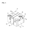
- Fig. 1 is an oblique view of a battery pack for the first embodiment of the present invention
- the battery pack of the present invention is primarily installed on-board an electric motor-bike to supply power to a motor that drives the bike.
- the present invention since the present invention has many batteries arrayed in multiple rows and columns to increase output, it is optimal for use in high output applications such as an electric vehicle.
- the battery pack of the present invention is most suitable for use as a power source in an electric vehicle such as an electric motor-bike (including an electric motor scooter and an electric motorcycle), a bicycle with electrical-assist, an electric wheel-chair, an electric three-wheeled vehicle, and an electric go-cart.
- an electric vehicle such as an electric motor-bike (including an electric motor scooter and an electric motorcycle), a bicycle with electrical-assist, an electric wheel-chair, an electric three-wheeled vehicle, and an electric go-cart.
- an electric motor-bike including an electric motor scooter and an electric motorcycle
- a bicycle with electrical-assist an electric wheel-chair
- an electric three-wheeled vehicle an electric go-cart.
- the following describes
- the battery pack of Figs. 1-5 has a plurality of batteries 1 disposed in multiple rows and columns in battery holders 2 to form battery blocks 10, and a plurality of battery blocks 10 are housed in a battery case 3.
- the battery pack of the figures has three battery blocks 10 arranged in three parallel rows inside the battery case 3.
- the battery pack of the figures has battery blocks 10 housed in a plastic battery case 3, the battery pack of the present invention does not necessarily require containment of the battery blocks in a battery case.
- the battery blocks can be covered with an insulating film such as heat-shrink film, or the battery blocks can be embedded in potting resin without housing them in a battery case.
- a battery block 10 is provided with a plurality of batteries 1 that can be charged, and a battery holder 2 that disposes the batteries 1 in multiple rows and columns, and in parallel orientation.
- the battery block 10 of the figures is provided with a circuit board 5 connected to the batteries 1 via lead-plates 4, and the circuit board 5 is disposed in a fixed position on the battery holder 2.
- the batteries 1 are lithium ion rechargeable batteries. However, the batteries can also be nickel-hydride batteries or nickel-cadmium batteries. Further, although the batteries 1 in the battery pack of the figures are circular cylindrical batteries the batteries can also be rectangular batteries.
- the battery block 10 of the figures has batteries arranged in parallel orientation in multiple rows and columns, and the battery holder 2 retains each battery 1 in a fixed position with the end planes of each battery 1 aligned in the same plane.
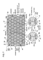
- the battery block 10 of the figures has a plurality of batteries 1 arranged in parallel orientation with ten batteries 1 arranged in a row and stacked in six rows to make a total array of sixty batteries 1. Specifically, the battery block 10 disposes batteries 1 in an array of six rows and ten columns.
- the battery block 10 of the figures has vertically adjacent batteries 1 offset to fill the valleys between batteries 1 and dispose the batteries 1 in zigzagging vertical columns.
- the battery block 10 of the figures disposes batteries 1 in six rows and ten columns, the present invention does not limit the number of batteries or the battery array configuration of the battery blocks.
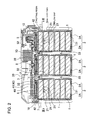
- the battery pack of Figs. 2-5 has three battery blocks 10 housed in the battery case 3. Therefore, the battery pack is provided with a total of 180 batteries 1.
- the battery pack of the present invention does not specify the number of battery blocks housed in the battery case, and these types of specifications are set to numbers optimal for the application.
- a plurality of batteries 1 are connected in series and parallel by weld-attaching lead-plates 4 to both ends of each battery 1.
- the lead-plates 4 connect batteries 1 in the same row in series, and connect batteries 1 disposed in the same zigzagging column in parallel.
- the lead-plates 4 are metal plates welded to the electrode terminals at the ends of the batteries 1 to connect batteries 1 in the same column parallel. Since the battery block 10 of Figs. 6-9 has batteries 1 in the same column disposed in a zigzag pattern, the lead-plates 4 also have a zigzag shape.
- a lead-plate 4 that connects batteries 1 in adjacent columns in series has a zigzag shape and a width that can connect two columns of batteries 1 together. In the battery block 10 of Fig.
- lead-plates 4 connect ten batteries 1 in series and six batteries 1 in parallel. Specifically, sixty batteries 1 are connected ten in series and six in parallel by the lead-plates 4.
- the output voltage of the battery pack can be adjusted by the number of batteries 1 connected in series, and the output current can be adjusted by the number of batteries 1 connected in parallel. Since the battery block 10 of the figures has ten batteries 1 connected in series, output voltage is ten times the battery voltage. Accordingly, a battery block 10 that uses lithium ion batteries with a specified voltage of 3.7V has an output voltage of 37V.
- each lead-plate 4 is connected to the circuit board 5 mounted on the battery holder 2. This allows protection circuitry (not illustrated) on the circuit board 5 to detect the voltage of each battery 1.
- Each lead-plate 4 is provided with a connecting tab 4A protruding from one end that connects to the circuit board 5.
- Each lead-plate 4 has a lead-wire 6 connected to the connecting tab 4A to connect the lead-plates 4 to the circuit board 5 protection circuitry.
- a battery holder 2 is provided with insertion sections 21 separated by dividing walls 22 to insert and hold the batteries 1 in fixed positions. Batteries inserted in the insertion sections 21 make contact with the dividing walls 22 in a thermally coupled manner. Heat generated by the batteries 1 is transferred to, and dissipated in the battery holder 2.
- the battery holder 2 holds batteries 1 inserted in the insertion sections 21 in fixed positions.
- the battery holder 2 is fabricated by molding insulating plastic. Since the battery block 10 shown in the figures is provided with sixty batteries 1, the battery holder 2 is shaped with dividing walls 22 that establish sixty insertion sections 21 and is formed entirely from plastic as an integrated structure.
- the insertion sections 21 have both ends open to allow electrode terminals at the ends of the inserted batteries 1 to be exposed to the outside.
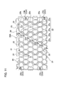
- the thickness of the battery holder 2 dividing walls 22 increases from the periphery regions to the center regions. Since the battery block 10 of Figs. 7 , 9 , and 11 has circular cylindrical batteries 1, the battery holder 2 insertion sections 21 are circular cylinders that conform to the battery 1 surfaces. In this battery holder 2, dividing wall 22 thickness varies with position, and adjacent circular cylindrical battery 1 surfaces are closest in regions where the dividing walls 22 are thinnest. The thin part 22a of the battery holder 2 dividing walls 22 becomes thicker at center regions than at periphery regions. In the battery holder 2 of Fig.
- the thin part 22a of the dividing walls 22 in this battery block 10 which has batteries 1 disposed in multiple rows, becomes thicker towards the center row of batteries 1, the thickness of the thin part 22b of dividing walls 22 in the same row is the same.
- the thickness of battery holder dividing walls in the same row can also vary to become thicker at the center than at the periphery.
- the heat capacity of dividing walls 22 thermally coupled with batteries 1 disposed in center regions is greater than the heat capacity of dividing walls 22 thermally coupled with batteries 1 disposed in periphery regions. This is because the heat capacity of the dividing walls 22 is proportional to the product of their specific heat and volume. Dividing walls 22 with large heat capacity can reduce the temperature rise corresponding to a given amount of heat energy absorbed from the batteries 1. Therefore, by making the heat capacity of dividing walls 22 thermally coupled with batteries 1 disposed in center regions greater than that of dividing walls 22 thermally coupled with batteries 1 disposed in periphery regions, the temperature rise of batteries 1 disposed in the center regions can be reduced.
- the temperature of batteries 1 in the periphery regions tends to be lower.
- the temperature of batteries 1 in the center regions has a tendency to become higher.
- the amount of battery 1 heat energy absorbed by dividing walls 22 at the center regions can be increased and the temperature rise of the center region batteries 1 can be reduced.
- temperature differences between batteries 1 disposed in the periphery regions and batteries 1 disposed in the center regions can be reduced.
- the battery pack of Figs. 2 and 3 has battery blocks 10 inserted in the battery case 3 and those battery blocks 10 are embedded in potting resin 7. All the batteries 1 can be completely embedded in potting resin 7 to thermally couple each battery 1 in an ideal manner with the battery case 3. However, it is not necessary to completely embed all the batteries 1 in potting resin 7. For example, a configuration that leaves part of the top row of batteries 1 just contacting the potting resin 7 is also possible. In a battery pack filled with potting resin 7, potting resin 7 can fill between the batteries 1 and the battery holder 2 insertion sections 21 to thermally couple the batteries 1 and the battery holders 2 in an ideal manner.
- the battery holder 2 shown in Figs. 6 , 8 , and 9 is divided into a pair of holder units 2A.
- the ends of each battery 1 are inserted into the insertion sections 21 of the separated holder units 2A to dispose the batteries 1 in fixed positions.
- Each holder unit 2A is provided with insertion sections 21 that can accept insertion of approximately half of each battery 1, and each battery 1 is inserted in a pair of holder units 2A to retain it in a fixed position.
- fasteners 23 are provided to set the relative position for joining the pair of holder units 2A.
- the fasteners 23 are configured to join a pair of holder units 2A in a manner that establishes flow gaps 24 that pass potting resin 7 between opposing surfaces of the holder units 2A.
- the fasteners 23 join a pair of holder units 2A in a manner that establishes flow gaps 24 between opposing surfaces that are for example, 1 mm to 10mm, preferably 2mm to 8mm, and more preferably 3mm to 6mm.
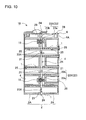
- the fasteners 23 shown in Fig. 10 are connecting bosses 23X that protrude from the opposing surfaces of a pair of holder units 2A.
- the fasteners 23, which are connecting bosses 23X are formed from plastic in single-piece construction with the holder units 2A.
- the connecting bosses 23X on one side have connecting projections 23a with circular cylindrical ends, and the ends of the connecting bosses 23X on the other side are provided with connecting cylinders 23b that accept insertion of the connecting projections 23a.
- These fasteners 23 join a pair of holder units 2A and establish flow gaps 24 by inserting the connecting projections 23a of the connecting bosses 23X on one side into the connecting cylinders 23b of the connecting bosses 23X on the other side.
- the holder units 2A have connecting bosses 23X established in the four corner regions of their opposing surfaces.
- the fasteners 23X are established in a plurality of locations to join the holder units 2A while forming flow gaps 24.
- the size of the flow gaps 24 can be set by the amount of protrusion of the connecting bosses 23X from the opposing surfaces of the holder units 2A. Specifically, the amount of protrusion of the connecting bosses 23X is a height that forms a given flow gap 24 width when the connecting projections 23a are inserted in the connecting cylinders 23b.
- a pair of holder units 2A connected via the fasteners 23 described above allows potting resin 7 filling the battery case 3 to flow smoothly from the flow gaps 24 into the insertion sections 21 and fill without forming vacancies.
- potting resin 7 can fill between the batteries 1 and the insertion sections 21 without forming vacancies.
- each holder unit 2A insertion section 21 tapers from holder unit 2A opposing surfaces, which have flow gaps 24 established, towards the battery 1 end regions. Specifically, by tapering the insides of the insertion sections 21 from the center of the battery holder 2 towards both end regions, potting resin 7 flowing in from the flow gaps 24 can be introduced more smoothly into the insertion sections 21.
- the insertion sections 21 that dispose the circular cylindrical batteries 1 in fixed positions have circular cylindrical shapes, the inside diameter of the insertion sections 21 becomes smaller from the center region towards both end regions, and the inside diameter of both ends of the insertion sections 21 is approximately equal to the outside diameter of the batteries 1 to retain the batteries 1 accurately in fixed positions.
- batteries 1 can also be smoothly inserted into each holder unit 2A insertion section 21. Further, with the batteries 1 inserted in the insertion sections 21, both ends of the batteries 1 contact the inside surfaces of the insertion sections 21 to hold the batteries 1 in fixed positions.
- a battery holder 2 with potting resin 7 that fills the insertion sections 21 can be provided with filling grooves 25 on the insides surfaces of the insertion sections 21 extending in the lengthwise direction of the batteries 1.
- the filling grooves 25 are provided in a plurality of rows on the inside surface of each insertion section 21.
- potting resin 7 in a viscous fluid state introduced from the flow gaps 24 between the holder units 2A can flow into the filling grooves 25 to smoothly fill the space between the batteries 1 and the insertion sections 21 without vacancies.
- the battery holder 2 has lead-plates 4 disposed at the openings established at both ends of the insertion sections 21.
- the lead-plates 4 are disposed outside the insertion sections 21 and are weld-attached to the ends of the batteries 21 exposed outside the open ends of the insertion sections 21.
- the battery holder 2 of Figs. 6 and 8 is provided with alignment cavities 26 at the open ends of the insertion sections 21 that mate with the lead-plates 4, and the lead-plates 4 are fitted into those alignment cavities 26 and held in fixed positions.
- the shape of the alignment cavities 26 is made slightly larger than the outline of the lead-plates 4, and the lead-plates 4 are inserted in the alignment cavities 26 and disposed in fixed positions.
- a battery holder 2 that is formed in separate pieces is connected by screwing set screws 19 into the connecting bosses 23X, which are formed in single-piece construction.
- the battery holder 2 of Fig. 9 is provided with connecting bosses 23X formed in single-piece construction at the perimeter of the battery holder 2.
- the connecting bosses 23X have cylindrical shapes and set screws 19 are inserted inside the cylindrical connecting bosses 23X.
- a battery holder 2 formed in separate pieces can also be joined in a locking fit configuration, joined by bonding, or joined by a combination of these methods.
- the battery pack of the present invention does not limit the battery holder to that structure.
- the battery holder can also be any other structure that can dispose a plurality of batteries in fixed positions in insertion sections.
- the battery holder can also be a single piece that does not divide into sub-components, or it can be a structure made up of two or more separate pieces.
- the battery pack of the present invention does not necessarily require the batteries to be embedded in potting resin. In this type of battery pack, contact surface area of the batteries and the inside surfaces of the battery holder insertion sections is increased to thermally couple the batteries and the battery holder.
- the battery block 10 of Figs. 6 and 7 has a circuit board 5 mounted on its top surface.
- the battery block 10 of the figures which has batteries 1 oriented horizontally, has the circuit board 5 disposed in a horizontal orientation.
- the battery holder 2 shown in the figures is provided with a circuit board mounting section 27 that aligns the circuit board 5 in a fixed position.
- the battery holder 2 shown in the figures has alignment ribs 28 formed in single-piece construction projecting upward around the perimeter of the top surface to establish the circuit board mounting section 27.
- the battery holder 2 of the figures is a pair of battery holders 2A joined together and alignment ribs 28 are provided around the top surface perimeter edges of each holder unit 2A except along opposing edges. This allows the circuit board 5 to be disposed on the top surface of the battery holder 2.
- the circuit board mounting section 27 alignment rib 28 outline has a shape that conforms to the perimeter of the circuit board 5.
- the battery holder 2 shown in the figures is provided with connecting bosses 29 formed in single-piece construction that protrude from the top surface.
- the circuit board 5 is mounted on the connecting bosses 29 via set screws 18 to dispose the circuit board 5 in a position separated from the top surface of the battery holder 2.
- the circuit board 5 can have electronic components (not illustrated) mounted on the side opposite the battery holder 2 to implement circuitry such as protection circuitry.
- the circuit board can also be mounted on the battery holder in a locking fit configuration instead of using set screws.
- alignment ribs 28 opposite edges on both sides of the circuit board 5 are provided with cut-outs 28A to run circuit board 5 lead-wires 6 off the circuit board 5.
- the cut-outs 28A are provided in positions corresponding to the positions of the lead-wires 6 attached to the circuit board 5.
- the lead-wires 6 can be disposed without running them over the tops of the alignment ribs 28.
- the lead-wires 6 extending off the circuit board 5 through the cut-outs 28A are connected to the connecting tabs 4A on the lead-plates 4 to connect the lead-plates 4 to the circuit board 5.
- the circuit board 5 is connected to the batteries 1 via the lead-wires 6 and the lead-plates 4.
- the circuit board 5 implements circuitry such as control circuitry (not illustrated) that detects the voltage of each battery 1 and controls charging and discharging of the plurality of batteries 1, and protection circuitry (not illustrated) that cuts-off charging and discharging current.
- the protection circuitry switches a switching device OFF to cut-off discharging current when the voltage of any battery drops below a minimum voltage. Protection circuitry also switches a switching device OFF to stop charging when the voltage of any battery becomes greater than a maximum voltage.
- a battery pack having protection circuitry implemented to detect the voltage of each battery and control charging and discharging can be operated safely while protecting the batteries 1.
- circuit board 5 also implements temperature detection circuitry that detects abnormal battery 1 temperature.
- Circuit board 5 temperature detection circuitry detects abnormal battery 1 temperature rise and controls battery 1 charging and discharging by operations such as restraining battery 1 charging and discharging current or stopping charging and discharging.
- the battery case 3 is fabricated by molding plastic.
- the battery case 3 of Figs. 2-5 is formed in a box shape with an open top.
- This battery case 3 houses three battery blocks 10 arranged in parallel orientation and has hollow partitions 32 provided between the three battery blocks 10 for cooling.
- the hollow partitions 32 extend upward from the bottom panel 31 of the battery case 3, and hollow regions 33 open at the bottom are established inside the hollow partitions 32.
- These hollow partitions 32 are in close proximity to the battery blocks 10 disposed on both sides, are thermally coupled to the battery blocks 10, and radiate battery block 10 heat outside the battery case 3.
- the hollow partitions 32 increase the heat radiating surface area in contact with the ambient air to efficiently radiate battery 1 heat to the outside.
- the hollow partitions 32 can suppress conditions that induce thermal runaway of the battery blocks 10 disposed on both sides of the hollow partitions 32. This is because abnormal temperature rise in a battery block 10 on one side of a hollow partition 32 is isolated by the hollow region 33 inside the hollow partition 32.
- the battery pack of the figures is provided with a connecting plate 40 that connects a plurality of battery blocks 10.
- the connecting plate 40 is disposed on the top surfaces of the plurality of battery blocks 10, is attached to each battery block 10 via set screws (not illustrated), and joins the plurality of battery blocks 10 as a single unit. Since the battery blocks 10 of the figures have circuit boards 5 mounted on their top surfaces, the circuit boards 5 are disposed between the connecting plate 40 and the battery holders 2 and are protected by the connecting plate 40.
- the plurality of battery blocks 10 can be joined as a single unit by the connecting plate 40 and housed in the battery case 3 while protecting the circuit boards 5 with the connecting plate 40.
- the connecting plate 40 is fabricated by molding plastic.
- the connecting plate 40 of Fig. 4 has perimeter walls 42 formed in single-piece construction projecting upward and downward along the perimeter of a base plate 41, which is disposed opposite the top surfaces of the plurality of battery blocks 10.
- the perimeter walls 42 have an outline that conforms to the inside surfaces of the open top of the battery case 3 to fit the connecting plate 40 inside the edges of the open region of the battery case 3.
- the connecting plate 40 has a primary circuit board 60 mounted on its upper surface.
- the primary circuit board 60 is connected to the circuit boards 5 mounted on each battery block 10 via lead-wires (not illustrated).
- the primary circuit board 60 implements protection circuitry (not illustrated) that inputs signals from each circuit board 5 and controls battery 1 charging and discharging.
- Electronic components (not illustrated) are mounted on the primary circuit board 60 to implement circuitry such as switching devices that control discharging current based on signals input from the circuit boards 5, and relay control circuitry that controls battery 1 current.
- a switching device can be switched OFF to cut-off battery 1 current when the voltage of any battery 1 becomes greater than a maximum voltage, when the voltage of any battery 1 becomes less than a minimum voltage, when battery 1 temperature becomes greater than a maximum temperature, or when battery 1 temperature becomes less than a minimum temperature.
- a battery pack which detects parameters such as the voltage and temperature of each battery 1 and controls battery current, can be safely operated while protecting the batteries 1.
- the plurality of battery blocks 10 are joined as a unit by the connecting plate 40 and held in a battery case 3.
- a battery case 3 divided by hollow partitions 32 houses a battery block 10 in each partitioned section.
- the connecting plate 40 that joins the plurality of battery blocks 10 is fit into the open region of the battery case 3 and held in place by set screws (not illustrated).
- the battery pack is filled with potting resin 7 in a manner that embeds the battery blocks 10, and more specifically embeds the batteries 1, housed in the battery case 3.
- the potting resin 7 is a resin such as urethane resin, epoxy resin, or silicone resin that is introduced in the unhardened viscous fluid state to embed the batteries 1 and battery holders 2.
- potting resin 7 adheres closely to the inside surfaces of the battery case 3 without forming vacancies to form ideal thermal coupling between the potting resin 7 and the battery case 3.
- a battery pack with batteries embedded in potting resin can also be formed by inserting the battery blocks in shaping containers, filling the shaping containers with potting resin, removing the battery blocks from the shaping containers after potting resin hardening, and inserting the battery blocks in the battery case.
- the inside shape of the shaping containers equivalent to the inside shape of the battery case, the potting resin can make close contact with the inside surfaces of the battery case. Since the battery blocks embedded in potting resin in this battery pack can be removed from the battery case, it has the feature that maintenance such as battery block replacement can be performed.
- the battery pack described above is assembled in the following manner.
Applications Claiming Priority (1)
| Application Number | Priority Date | Filing Date | Title |
|---|---|---|---|
| JP2009196094A JP5496576B2 (ja) | 2009-08-26 | 2009-08-26 | バッテリパック |
Publications (2)
| Publication Number | Publication Date |
|---|---|
| EP2290731A1 true EP2290731A1 (de) | 2011-03-02 |
| EP2290731B1 EP2290731B1 (de) | 2016-10-12 |
Family
ID=43297148
Family Applications (1)
| Application Number | Title | Priority Date | Filing Date |
|---|---|---|---|
| EP10008860.8A Active EP2290731B1 (de) | 2009-08-26 | 2010-08-25 | Batteriepack |
Country Status (3)
| Country | Link |
|---|---|
| EP (1) | EP2290731B1 (de) |
| JP (1) | JP5496576B2 (de) |
| CN (1) | CN102005599B (de) |
Cited By (20)
| Publication number | Priority date | Publication date | Assignee | Title |
|---|---|---|---|---|
| DE102011009768A1 (de) * | 2011-01-28 | 2012-08-02 | Bombardier Transportation Gmbh | Halten einer Mehrzahl von elektrischen Energiespeicherzellen |
| CN102870253A (zh) * | 2011-03-17 | 2013-01-09 | 松下电器产业株式会社 | 电池块 |
| CN103178220A (zh) * | 2011-12-26 | 2013-06-26 | 河南科隆集团有限公司 | 一种新型电动车电池支架 |
| CN103176133A (zh) * | 2011-12-26 | 2013-06-26 | 河南科隆集团有限公司 | 一种新型电池soc采集信号板 |
| US20140050962A1 (en) * | 2012-08-16 | 2014-02-20 | C. & E. Fein Gmbh | Compact rechargeable battery - screw connection of cell holders |
| EP2744015A1 (de) * | 2011-08-10 | 2014-06-18 | Panasonic Corporation | Batterieblock und batteriemodul damit |
| EP2782206A1 (de) * | 2013-03-19 | 2014-09-24 | Kabushiki Kaisha Toshiba | Steuervorrichtung für eine Sekundärbatterie |
| EP2797138A1 (de) * | 2013-04-23 | 2014-10-29 | Samsung SDI Co., Ltd. | Batteriepack |
| WO2015065254A1 (en) * | 2013-10-30 | 2015-05-07 | Husqvarna Ab | Flexible battery cell retainer |
| US9153799B2 (en) | 2013-04-29 | 2015-10-06 | Lg Chem, Ltd. | Battery module for vehicle's battery pack |
| US9209637B2 (en) | 2013-03-15 | 2015-12-08 | Kabushiki Kaisha Toshiba | Battery control apparatus |
| US9768426B2 (en) | 2011-06-01 | 2017-09-19 | Elringklinger Ag | Cover for an electro-chemical device |
| EP3264495A1 (de) * | 2016-07-01 | 2018-01-03 | Optimum Battery Co., Ltd. | Stromabnehmende plattenanordnung und batteriepack damit |
| WO2019229006A1 (de) | 2018-05-28 | 2019-12-05 | Robert Bosch Gmbh | Gehäuse für ein batteriemodul und batteriemodul |
| EP3758087A4 (de) * | 2018-02-22 | 2021-03-24 | SANYO Electric Co., Ltd. | Batteriepack und verfahren zur herstellung davon |
| WO2021181199A1 (en) * | 2020-03-10 | 2021-09-16 | Poynting Antennas (Pty) Limited | Battery assembly |
| CN113767514A (zh) * | 2019-11-25 | 2021-12-07 | 株式会社Lg新能源 | 电池模块及电池组 |
| US11233285B2 (en) | 2018-01-17 | 2022-01-25 | Lg Chem, Ltd. | Multilayered cylindrical battery module having heat dissipation and chain ignition preventing structure and battery pack comprising same |
| WO2022216839A1 (en) * | 2021-04-07 | 2022-10-13 | Rad Power Bikes Inc. | Battery packs for electric bicycles |
| SE2250769A1 (en) * | 2022-06-22 | 2023-12-23 | Northvolt Ab | Wrapping for a cell in a potted battery module |
Families Citing this family (23)
| Publication number | Priority date | Publication date | Assignee | Title |
|---|---|---|---|---|
| JP5651444B2 (ja) * | 2010-11-30 | 2015-01-14 | パナソニックIpマネジメント株式会社 | 電池モジュール |
| CN103515554A (zh) * | 2012-06-27 | 2014-01-15 | 李佳原 | 防水、防火、防震、防爆四合一的车用电池及其制造方法 |
| JP5942645B2 (ja) * | 2012-07-05 | 2016-06-29 | 株式会社デンソー | 電池ユニット |
| JP2014044884A (ja) * | 2012-08-27 | 2014-03-13 | Sanyo Electric Co Ltd | バッテリシステム及びバッテリシステムを備える電動車両並びに蓄電装置 |
| WO2014178565A1 (ko) * | 2013-04-29 | 2014-11-06 | 주식회사 엘지화학 | 자동차용 배터리 팩에 포함되는 배터리 모듈 |
| US10347894B2 (en) | 2017-01-20 | 2019-07-09 | Tesla, Inc. | Energy storage system |
| CN104576994B (zh) * | 2014-12-19 | 2017-08-11 | 广东亿纬赛恩斯新能源系统有限公司 | 电池成组结构及包含其的电池组 |
| TWI678018B (zh) * | 2015-10-01 | 2019-11-21 | 英屬開曼群島商睿能創意公司 | 攜帶型電能儲存裝置 |
| DE102015219280A1 (de) * | 2015-10-06 | 2017-04-06 | Robert Bosch Gmbh | Batteriesystem mit Vergussmasse |
| JP6685001B2 (ja) * | 2015-11-12 | 2020-04-22 | パナソニックIpマネジメント株式会社 | 電池パック |
| US10693112B2 (en) * | 2016-01-21 | 2020-06-23 | Panasonic Intellectual Property Management Co., Ltd. | Battery module |
| US10916744B2 (en) * | 2016-06-29 | 2021-02-09 | Panasonic Intellectual Property Management Co., Ltd. | Battery block |
| JP6846135B2 (ja) * | 2016-08-23 | 2021-03-24 | 藤森工業株式会社 | 組電池 |
| WO2018037860A1 (ja) * | 2016-08-24 | 2018-03-01 | パナソニックIpマネジメント株式会社 | 電池モジュール |
| DE102016220989A1 (de) * | 2016-10-25 | 2018-04-26 | Robert Bosch Gmbh | Batteriezellhalter zur federelastischen Aufnahme mindestens einer Batteriezelle, Batteriemodulgehäuse und Batteriemodul sowie Verfahren zur Herstellung des Batteriemoduls |
| KR102172516B1 (ko) | 2016-12-14 | 2020-10-30 | 주식회사 엘지화학 | 조립 구조가 개선된 공냉식 배터리 팩 |
| WO2018179733A1 (ja) * | 2017-03-31 | 2018-10-04 | 三洋電機株式会社 | 電池パック |
| JP7174707B2 (ja) * | 2017-09-29 | 2022-11-17 | 三洋電機株式会社 | 電源装置 |
| DE102018100912B4 (de) * | 2018-01-17 | 2020-12-10 | Stöcklin Logistik Ag | Batteriestromversorgung für ein in einem explosionsgefährdeten Bereich eingesetztes Flurförderfahrzeug und Flurförderfahrzeug |
| JP7078892B2 (ja) * | 2018-03-14 | 2022-06-01 | トヨタ自動車株式会社 | 蓄電装置 |
| CN108767361B (zh) * | 2018-04-25 | 2020-10-20 | 中国科学院广州能源研究所 | 一种户外电池热管理的系统及方法 |
| US11145932B2 (en) | 2018-09-24 | 2021-10-12 | Milwaukee Electric Tool Corporation | Battery cell module and battery pack |
| CN111477792B (zh) * | 2020-04-15 | 2022-08-09 | 中车资阳机车有限公司 | 一种混合动力机车电池系统电池包及电池系统 |
Citations (8)
| Publication number | Priority date | Publication date | Assignee | Title |
|---|---|---|---|---|
| JP2003077440A (ja) | 2001-09-03 | 2003-03-14 | Sanyo Electric Co Ltd | 組電池 |
| US20070072061A1 (en) * | 2005-09-28 | 2007-03-29 | Hideo Shimizu | Power supply unit and method for cooling battery contained therein |
| WO2008034584A1 (de) * | 2006-09-18 | 2008-03-27 | Magna Steyr Fahrzeugtechnik Ag & Co Kg | Modulare batterieeinheit |
| DE102007010751A1 (de) * | 2007-02-27 | 2008-08-28 | Daimler Ag | Batteriegehäuse |
| DE102007010744A1 (de) * | 2007-02-27 | 2008-08-28 | Daimler Ag | Batteriezelle und Zellverbund einer Batterie |
| JP2009004163A (ja) | 2007-06-20 | 2009-01-08 | Toyota Motor Corp | 蓄電装置 |
| US20090111015A1 (en) * | 2006-05-11 | 2009-04-30 | Johnson Controls - Saft Advanced Power Solutions Llc | Modular battery system |
| DE102008034699A1 (de) * | 2008-07-26 | 2010-01-28 | Daimler Ag | Batterie mit mehreren Batteriezellen |
Family Cites Families (8)
| Publication number | Priority date | Publication date | Assignee | Title |
|---|---|---|---|---|
| JP4176884B2 (ja) * | 1998-10-08 | 2008-11-05 | ポリマテック株式会社 | 電気自動車のバッテリ格納構造および格納方法 |
| JP4641737B2 (ja) * | 2004-04-30 | 2011-03-02 | 三洋電機株式会社 | パック電池 |
| JP4958409B2 (ja) * | 2005-06-01 | 2012-06-20 | 三洋電機株式会社 | 組電池 |
| JP4849848B2 (ja) * | 2005-08-31 | 2012-01-11 | 三洋電機株式会社 | 組電池 |
| JP4993935B2 (ja) * | 2006-04-04 | 2012-08-08 | 三洋電機株式会社 | 組電池 |
| JP5173227B2 (ja) * | 2007-03-30 | 2013-04-03 | 三洋電機株式会社 | パック電池 |
| JP5294575B2 (ja) * | 2007-05-26 | 2013-09-18 | 三洋電機株式会社 | パック電池とその製造方法 |
| FR2924857B1 (fr) * | 2007-12-06 | 2014-06-06 | Valeo Equip Electr Moteur | Dispositif d'alimentation electrique comportant un bac de reception d'unites de stockage a ultra capacite |
-
2009
- 2009-08-26 JP JP2009196094A patent/JP5496576B2/ja active Active
-
2010
- 2010-08-25 CN CN201010264025.4A patent/CN102005599B/zh active Active
- 2010-08-25 EP EP10008860.8A patent/EP2290731B1/de active Active
Patent Citations (8)
| Publication number | Priority date | Publication date | Assignee | Title |
|---|---|---|---|---|
| JP2003077440A (ja) | 2001-09-03 | 2003-03-14 | Sanyo Electric Co Ltd | 組電池 |
| US20070072061A1 (en) * | 2005-09-28 | 2007-03-29 | Hideo Shimizu | Power supply unit and method for cooling battery contained therein |
| US20090111015A1 (en) * | 2006-05-11 | 2009-04-30 | Johnson Controls - Saft Advanced Power Solutions Llc | Modular battery system |
| WO2008034584A1 (de) * | 2006-09-18 | 2008-03-27 | Magna Steyr Fahrzeugtechnik Ag & Co Kg | Modulare batterieeinheit |
| DE102007010751A1 (de) * | 2007-02-27 | 2008-08-28 | Daimler Ag | Batteriegehäuse |
| DE102007010744A1 (de) * | 2007-02-27 | 2008-08-28 | Daimler Ag | Batteriezelle und Zellverbund einer Batterie |
| JP2009004163A (ja) | 2007-06-20 | 2009-01-08 | Toyota Motor Corp | 蓄電装置 |
| DE102008034699A1 (de) * | 2008-07-26 | 2010-01-28 | Daimler Ag | Batterie mit mehreren Batteriezellen |
Cited By (31)
| Publication number | Priority date | Publication date | Assignee | Title |
|---|---|---|---|---|
| DE102011009768A1 (de) * | 2011-01-28 | 2012-08-02 | Bombardier Transportation Gmbh | Halten einer Mehrzahl von elektrischen Energiespeicherzellen |
| CN102870253A (zh) * | 2011-03-17 | 2013-01-09 | 松下电器产业株式会社 | 电池块 |
| US9548477B2 (en) | 2011-03-17 | 2017-01-17 | Panasonic Intellectual Property Management Co., Ltd. | Battery block |
| US20130344376A1 (en) * | 2011-03-17 | 2013-12-26 | Panasonic Corporation | Battery block |
| CN102870253B (zh) * | 2011-03-17 | 2015-04-08 | 松下电器产业株式会社 | 电池块 |
| US9768426B2 (en) | 2011-06-01 | 2017-09-19 | Elringklinger Ag | Cover for an electro-chemical device |
| EP2744015A4 (de) * | 2011-08-10 | 2014-12-24 | Panasonic Corp | Batterieblock und batteriemodul damit |
| EP2744015A1 (de) * | 2011-08-10 | 2014-06-18 | Panasonic Corporation | Batterieblock und batteriemodul damit |
| CN103178220B (zh) * | 2011-12-26 | 2017-06-13 | 河南科隆集团有限公司 | 一种电动车电池支架 |
| CN103176133A (zh) * | 2011-12-26 | 2013-06-26 | 河南科隆集团有限公司 | 一种新型电池soc采集信号板 |
| CN103178220A (zh) * | 2011-12-26 | 2013-06-26 | 河南科隆集团有限公司 | 一种新型电动车电池支架 |
| US20160365550A1 (en) * | 2012-08-16 | 2016-12-15 | C. & E. Fein Gmbh | Compact battery cell holder |
| US20140050962A1 (en) * | 2012-08-16 | 2014-02-20 | C. & E. Fein Gmbh | Compact rechargeable battery - screw connection of cell holders |
| US9209637B2 (en) | 2013-03-15 | 2015-12-08 | Kabushiki Kaisha Toshiba | Battery control apparatus |
| EP2782206A1 (de) * | 2013-03-19 | 2014-09-24 | Kabushiki Kaisha Toshiba | Steuervorrichtung für eine Sekundärbatterie |
| US9419261B2 (en) | 2013-04-23 | 2016-08-16 | Samsung Sdi Co., Ltd. | Battery pack |
| EP2797138A1 (de) * | 2013-04-23 | 2014-10-29 | Samsung SDI Co., Ltd. | Batteriepack |
| US9153799B2 (en) | 2013-04-29 | 2015-10-06 | Lg Chem, Ltd. | Battery module for vehicle's battery pack |
| US10347954B2 (en) * | 2013-10-30 | 2019-07-09 | Husqvarna Ab | Flexible battery cell retainer |
| WO2015065254A1 (en) * | 2013-10-30 | 2015-05-07 | Husqvarna Ab | Flexible battery cell retainer |
| US20160285143A1 (en) * | 2013-10-30 | 2016-09-29 | Husqvarna Ab | Flexible battery cell retainer |
| EP3264495A1 (de) * | 2016-07-01 | 2018-01-03 | Optimum Battery Co., Ltd. | Stromabnehmende plattenanordnung und batteriepack damit |
| US20180006279A1 (en) * | 2016-07-01 | 2018-01-04 | Optimum Battery Co., Ltd. | Current collecting board assembly and power battery pack using same |
| US11233285B2 (en) | 2018-01-17 | 2022-01-25 | Lg Chem, Ltd. | Multilayered cylindrical battery module having heat dissipation and chain ignition preventing structure and battery pack comprising same |
| EP3758087A4 (de) * | 2018-02-22 | 2021-03-24 | SANYO Electric Co., Ltd. | Batteriepack und verfahren zur herstellung davon |
| WO2019229006A1 (de) | 2018-05-28 | 2019-12-05 | Robert Bosch Gmbh | Gehäuse für ein batteriemodul und batteriemodul |
| CN113767514A (zh) * | 2019-11-25 | 2021-12-07 | 株式会社Lg新能源 | 电池模块及电池组 |
| EP3937299A4 (de) * | 2019-11-25 | 2022-06-22 | LG Energy Solution, Ltd. | Batteriemodul und batteriesatz |
| WO2021181199A1 (en) * | 2020-03-10 | 2021-09-16 | Poynting Antennas (Pty) Limited | Battery assembly |
| WO2022216839A1 (en) * | 2021-04-07 | 2022-10-13 | Rad Power Bikes Inc. | Battery packs for electric bicycles |
| SE2250769A1 (en) * | 2022-06-22 | 2023-12-23 | Northvolt Ab | Wrapping for a cell in a potted battery module |
Also Published As
| Publication number | Publication date |
|---|---|
| CN102005599B (zh) | 2014-06-18 |
| JP5496576B2 (ja) | 2014-05-21 |
| CN102005599A (zh) | 2011-04-06 |
| JP2011049011A (ja) | 2011-03-10 |
| EP2290731B1 (de) | 2016-10-12 |
Similar Documents
| Publication | Publication Date | Title |
|---|---|---|
| EP2290731B1 (de) | Batteriepack | |
| EP2290728A1 (de) | Batteriepack | |
| KR100700277B1 (ko) | 카트리지 타입의 전지팩 | |
| JP6750117B2 (ja) | クラッシュビーム及び排水構造を有するバッテリーパック | |
| JP2011049013A (ja) | バッテリパック | |
| KR101166023B1 (ko) | 방열 효율이 향상된 팩 전지 | |
| US9608298B2 (en) | Battery pack | |
| JP5178154B2 (ja) | 組電池ユニットと複数の組電池ユニットを備える電池電源システム | |
| KR100904373B1 (ko) | 이차전지 모듈용 방열 구조물, 및 그것을 포함하는 스위칭보드 및 이차전지 모듈 | |
| KR101252936B1 (ko) | 배터리 팩 | |
| EP1753069A1 (de) | Batteriemodul | |
| EP2530761A1 (de) | Batteriepackung | |
| WO2001075989A2 (en) | Extended life battery pack with active cooling | |
| JP2011049014A (ja) | 防水構造のバッテリパック | |
| JP2009218011A (ja) | バッテリパック | |
| JP4492002B2 (ja) | 電池モジュール | |
| JP5142521B2 (ja) | パック電池 | |
| JP2008198435A (ja) | バッテリパック | |
| JP7318102B2 (ja) | 上部冷却方式バッテリーパック | |
| JP2008251472A (ja) | パック電池 | |
| WO2018179734A1 (ja) | 電池パック | |
| JP7305025B2 (ja) | バッテリーモジュールの機械的固定構造と電気的固定構造とを統合したバッテリーパック | |
| KR20060037598A (ko) | 전지 모듈 | |
| CN113939948A (zh) | 包括单元框架的电池模块 | |
| KR101806417B1 (ko) | 전력 저장 장치의 단위 전지 팩 |
Legal Events
| Date | Code | Title | Description |
|---|---|---|---|
| PUAI | Public reference made under article 153(3) epc to a published international application that has entered the european phase |
Free format text: ORIGINAL CODE: 0009012 |
|
| AK | Designated contracting states |
Kind code of ref document: A1 Designated state(s): AL AT BE BG CH CY CZ DE DK EE ES FI FR GB GR HR HU IE IS IT LI LT LU LV MC MK MT NL NO PL PT RO SE SI SK SM TR |
|
| AX | Request for extension of the european patent |
Extension state: BA ME RS |
|
| 17P | Request for examination filed |
Effective date: 20110831 |
|
| 17Q | First examination report despatched |
Effective date: 20111026 |
|
| REG | Reference to a national code |
Ref country code: DE Ref legal event code: R079 Ref document number: 602010037072 Country of ref document: DE Free format text: PREVIOUS MAIN CLASS: H01M0002100000 Ipc: H01M0010600000 |
|
| GRAP | Despatch of communication of intention to grant a patent |
Free format text: ORIGINAL CODE: EPIDOSNIGR1 |
|
| RIC1 | Information provided on ipc code assigned before grant |
Ipc: H01M 10/60 20140101AFI20160229BHEP |
|
| INTG | Intention to grant announced |
Effective date: 20160407 |
|
| GRAS | Grant fee paid |
Free format text: ORIGINAL CODE: EPIDOSNIGR3 |
|
| GRAA | (expected) grant |
Free format text: ORIGINAL CODE: 0009210 |
|
| RIN1 | Information on inventor provided before grant (corrected) |
Inventor name: HAINO, MASAMI Inventor name: YONEDA, HARUHIKO |
|
| RAP1 | Party data changed (applicant data changed or rights of an application transferred) |
Owner name: SANYO ELECTRIC CO., LTD. |
|
| AK | Designated contracting states |
Kind code of ref document: B1 Designated state(s): AL AT BE BG CH CY CZ DE DK EE ES FI FR GB GR HR HU IE IS IT LI LT LU LV MC MK MT NL NO PL PT RO SE SI SK SM TR |
|
| REG | Reference to a national code |
Ref country code: GB Ref legal event code: FG4D |
|
| REG | Reference to a national code |
Ref country code: CH Ref legal event code: EP |
|
| REG | Reference to a national code |
Ref country code: AT Ref legal event code: REF Ref document number: 837236 Country of ref document: AT Kind code of ref document: T Effective date: 20161015 |
|
| REG | Reference to a national code |
Ref country code: IE Ref legal event code: FG4D |
|
| REG | Reference to a national code |
Ref country code: DE Ref legal event code: R096 Ref document number: 602010037072 Country of ref document: DE |
|
| REG | Reference to a national code |
Ref country code: CH Ref legal event code: NV Representative=s name: KASCHE AND PARTNER AG, CH |
|
| REG | Reference to a national code |
Ref country code: LT Ref legal event code: MG4D |
|
| REG | Reference to a national code |
Ref country code: NL Ref legal event code: MP Effective date: 20161012 |
|
| PG25 | Lapsed in a contracting state [announced via postgrant information from national office to epo] |
Ref country code: LV Free format text: LAPSE BECAUSE OF FAILURE TO SUBMIT A TRANSLATION OF THE DESCRIPTION OR TO PAY THE FEE WITHIN THE PRESCRIBED TIME-LIMIT Effective date: 20161012 |
|
| REG | Reference to a national code |
Ref country code: AT Ref legal event code: MK05 Ref document number: 837236 Country of ref document: AT Kind code of ref document: T Effective date: 20161012 |
|
| PG25 | Lapsed in a contracting state [announced via postgrant information from national office to epo] |
Ref country code: GR Free format text: LAPSE BECAUSE OF FAILURE TO SUBMIT A TRANSLATION OF THE DESCRIPTION OR TO PAY THE FEE WITHIN THE PRESCRIBED TIME-LIMIT Effective date: 20170113 Ref country code: NO Free format text: LAPSE BECAUSE OF FAILURE TO SUBMIT A TRANSLATION OF THE DESCRIPTION OR TO PAY THE FEE WITHIN THE PRESCRIBED TIME-LIMIT Effective date: 20170112 Ref country code: LT Free format text: LAPSE BECAUSE OF FAILURE TO SUBMIT A TRANSLATION OF THE DESCRIPTION OR TO PAY THE FEE WITHIN THE PRESCRIBED TIME-LIMIT Effective date: 20161012 Ref country code: SE Free format text: LAPSE BECAUSE OF FAILURE TO SUBMIT A TRANSLATION OF THE DESCRIPTION OR TO PAY THE FEE WITHIN THE PRESCRIBED TIME-LIMIT Effective date: 20161012 |
|
| PG25 | Lapsed in a contracting state [announced via postgrant information from national office to epo] |
Ref country code: NL Free format text: LAPSE BECAUSE OF FAILURE TO SUBMIT A TRANSLATION OF THE DESCRIPTION OR TO PAY THE FEE WITHIN THE PRESCRIBED TIME-LIMIT Effective date: 20161012 Ref country code: AT Free format text: LAPSE BECAUSE OF FAILURE TO SUBMIT A TRANSLATION OF THE DESCRIPTION OR TO PAY THE FEE WITHIN THE PRESCRIBED TIME-LIMIT Effective date: 20161012 Ref country code: ES Free format text: LAPSE BECAUSE OF FAILURE TO SUBMIT A TRANSLATION OF THE DESCRIPTION OR TO PAY THE FEE WITHIN THE PRESCRIBED TIME-LIMIT Effective date: 20161012 Ref country code: IS Free format text: LAPSE BECAUSE OF FAILURE TO SUBMIT A TRANSLATION OF THE DESCRIPTION OR TO PAY THE FEE WITHIN THE PRESCRIBED TIME-LIMIT Effective date: 20170212 Ref country code: BE Free format text: LAPSE BECAUSE OF FAILURE TO SUBMIT A TRANSLATION OF THE DESCRIPTION OR TO PAY THE FEE WITHIN THE PRESCRIBED TIME-LIMIT Effective date: 20161012 Ref country code: HR Free format text: LAPSE BECAUSE OF FAILURE TO SUBMIT A TRANSLATION OF THE DESCRIPTION OR TO PAY THE FEE WITHIN THE PRESCRIBED TIME-LIMIT Effective date: 20161012 Ref country code: PT Free format text: LAPSE BECAUSE OF FAILURE TO SUBMIT A TRANSLATION OF THE DESCRIPTION OR TO PAY THE FEE WITHIN THE PRESCRIBED TIME-LIMIT Effective date: 20170213 Ref country code: PL Free format text: LAPSE BECAUSE OF FAILURE TO SUBMIT A TRANSLATION OF THE DESCRIPTION OR TO PAY THE FEE WITHIN THE PRESCRIBED TIME-LIMIT Effective date: 20161012 Ref country code: FI Free format text: LAPSE BECAUSE OF FAILURE TO SUBMIT A TRANSLATION OF THE DESCRIPTION OR TO PAY THE FEE WITHIN THE PRESCRIBED TIME-LIMIT Effective date: 20161012 |
|
| REG | Reference to a national code |
Ref country code: DE Ref legal event code: R097 Ref document number: 602010037072 Country of ref document: DE |
|
| PG25 | Lapsed in a contracting state [announced via postgrant information from national office to epo] |
Ref country code: EE Free format text: LAPSE BECAUSE OF FAILURE TO SUBMIT A TRANSLATION OF THE DESCRIPTION OR TO PAY THE FEE WITHIN THE PRESCRIBED TIME-LIMIT Effective date: 20161012 Ref country code: DK Free format text: LAPSE BECAUSE OF FAILURE TO SUBMIT A TRANSLATION OF THE DESCRIPTION OR TO PAY THE FEE WITHIN THE PRESCRIBED TIME-LIMIT Effective date: 20161012 Ref country code: CZ Free format text: LAPSE BECAUSE OF FAILURE TO SUBMIT A TRANSLATION OF THE DESCRIPTION OR TO PAY THE FEE WITHIN THE PRESCRIBED TIME-LIMIT Effective date: 20161012 Ref country code: RO Free format text: LAPSE BECAUSE OF FAILURE TO SUBMIT A TRANSLATION OF THE DESCRIPTION OR TO PAY THE FEE WITHIN THE PRESCRIBED TIME-LIMIT Effective date: 20161012 Ref country code: SK Free format text: LAPSE BECAUSE OF FAILURE TO SUBMIT A TRANSLATION OF THE DESCRIPTION OR TO PAY THE FEE WITHIN THE PRESCRIBED TIME-LIMIT Effective date: 20161012 |
|
| PLBE | No opposition filed within time limit |
Free format text: ORIGINAL CODE: 0009261 |
|
| STAA | Information on the status of an ep patent application or granted ep patent |
Free format text: STATUS: NO OPPOSITION FILED WITHIN TIME LIMIT |
|
| PG25 | Lapsed in a contracting state [announced via postgrant information from national office to epo] |
Ref country code: BG Free format text: LAPSE BECAUSE OF FAILURE TO SUBMIT A TRANSLATION OF THE DESCRIPTION OR TO PAY THE FEE WITHIN THE PRESCRIBED TIME-LIMIT Effective date: 20170112 Ref country code: IT Free format text: LAPSE BECAUSE OF FAILURE TO SUBMIT A TRANSLATION OF THE DESCRIPTION OR TO PAY THE FEE WITHIN THE PRESCRIBED TIME-LIMIT Effective date: 20161012 Ref country code: SM Free format text: LAPSE BECAUSE OF FAILURE TO SUBMIT A TRANSLATION OF THE DESCRIPTION OR TO PAY THE FEE WITHIN THE PRESCRIBED TIME-LIMIT Effective date: 20161012 |
|
| 26N | No opposition filed |
Effective date: 20170713 |
|
| PG25 | Lapsed in a contracting state [announced via postgrant information from national office to epo] |
Ref country code: SI Free format text: LAPSE BECAUSE OF FAILURE TO SUBMIT A TRANSLATION OF THE DESCRIPTION OR TO PAY THE FEE WITHIN THE PRESCRIBED TIME-LIMIT Effective date: 20161012 |
|
| PG25 | Lapsed in a contracting state [announced via postgrant information from national office to epo] |
Ref country code: MC Free format text: LAPSE BECAUSE OF FAILURE TO SUBMIT A TRANSLATION OF THE DESCRIPTION OR TO PAY THE FEE WITHIN THE PRESCRIBED TIME-LIMIT Effective date: 20161012 |
|
| GBPC | Gb: european patent ceased through non-payment of renewal fee |
Effective date: 20170825 |
|
| REG | Reference to a national code |
Ref country code: FR Ref legal event code: ST Effective date: 20180430 |
|
| REG | Reference to a national code |
Ref country code: IE Ref legal event code: MM4A |
|
| PG25 | Lapsed in a contracting state [announced via postgrant information from national office to epo] |
Ref country code: LU Free format text: LAPSE BECAUSE OF NON-PAYMENT OF DUE FEES Effective date: 20170825 |
|
| PG25 | Lapsed in a contracting state [announced via postgrant information from national office to epo] |
Ref country code: GB Free format text: LAPSE BECAUSE OF NON-PAYMENT OF DUE FEES Effective date: 20170825 Ref country code: IE Free format text: LAPSE BECAUSE OF NON-PAYMENT OF DUE FEES Effective date: 20170825 |
|
| PG25 | Lapsed in a contracting state [announced via postgrant information from national office to epo] |
Ref country code: FR Free format text: LAPSE BECAUSE OF NON-PAYMENT OF DUE FEES Effective date: 20170831 |
|
| PG25 | Lapsed in a contracting state [announced via postgrant information from national office to epo] |
Ref country code: MT Free format text: LAPSE BECAUSE OF NON-PAYMENT OF DUE FEES Effective date: 20170825 |
|
| PG25 | Lapsed in a contracting state [announced via postgrant information from national office to epo] |
Ref country code: HU Free format text: LAPSE BECAUSE OF FAILURE TO SUBMIT A TRANSLATION OF THE DESCRIPTION OR TO PAY THE FEE WITHIN THE PRESCRIBED TIME-LIMIT; INVALID AB INITIO Effective date: 20100825 |
|
| PG25 | Lapsed in a contracting state [announced via postgrant information from national office to epo] |
Ref country code: CY Free format text: LAPSE BECAUSE OF NON-PAYMENT OF DUE FEES Effective date: 20161012 |
|
| PG25 | Lapsed in a contracting state [announced via postgrant information from national office to epo] |
Ref country code: MK Free format text: LAPSE BECAUSE OF FAILURE TO SUBMIT A TRANSLATION OF THE DESCRIPTION OR TO PAY THE FEE WITHIN THE PRESCRIBED TIME-LIMIT Effective date: 20161012 |
|
| PG25 | Lapsed in a contracting state [announced via postgrant information from national office to epo] |
Ref country code: TR Free format text: LAPSE BECAUSE OF FAILURE TO SUBMIT A TRANSLATION OF THE DESCRIPTION OR TO PAY THE FEE WITHIN THE PRESCRIBED TIME-LIMIT Effective date: 20161012 |
|
| PG25 | Lapsed in a contracting state [announced via postgrant information from national office to epo] |
Ref country code: AL Free format text: LAPSE BECAUSE OF FAILURE TO SUBMIT A TRANSLATION OF THE DESCRIPTION OR TO PAY THE FEE WITHIN THE PRESCRIBED TIME-LIMIT Effective date: 20161012 |
|
| REG | Reference to a national code |
Ref country code: DE Ref legal event code: R081 Ref document number: 602010037072 Country of ref document: DE Owner name: PANASONIC ENERGY CO., LTD., MORIGUCHI-SHI, JP Free format text: FORMER OWNER: SANYO ELECTRIC CO., LTD., MORIGUCHI CITY, OSAKA, JP |
|
| P01 | Opt-out of the competence of the unified patent court (upc) registered |
Effective date: 20230808 |
|
| PGFP | Annual fee paid to national office [announced via postgrant information from national office to epo] |
Ref country code: CH Payment date: 20230902 Year of fee payment: 14 |
|
| PGFP | Annual fee paid to national office [announced via postgrant information from national office to epo] |
Ref country code: DE Payment date: 20230821 Year of fee payment: 14 |