EP2289776A2 - Dispositif d'entraînement secondaire pour une remorque - Google Patents
Dispositif d'entraînement secondaire pour une remorque Download PDFInfo
- Publication number
- EP2289776A2 EP2289776A2 EP10174200A EP10174200A EP2289776A2 EP 2289776 A2 EP2289776 A2 EP 2289776A2 EP 10174200 A EP10174200 A EP 10174200A EP 10174200 A EP10174200 A EP 10174200A EP 2289776 A2 EP2289776 A2 EP 2289776A2
- Authority
- EP
- European Patent Office
- Prior art keywords
- auxiliary drive
- operating
- vehicle
- drive
- auxiliary
- Prior art date
- Legal status (The legal status is an assumption and is not a legal conclusion. Google has not performed a legal analysis and makes no representation as to the accuracy of the status listed.)
- Granted
Links
- 238000001514 detection method Methods 0.000 claims description 43
- 230000006870 function Effects 0.000 claims description 25
- 230000011664 signaling Effects 0.000 claims description 12
- 235000014676 Phragmites communis Nutrition 0.000 claims description 5
- 238000004891 communication Methods 0.000 claims description 5
- 238000012806 monitoring device Methods 0.000 claims description 5
- 230000000903 blocking effect Effects 0.000 claims description 4
- 238000000034 method Methods 0.000 claims description 2
- 230000008878 coupling Effects 0.000 description 27
- 238000010168 coupling process Methods 0.000 description 27
- 238000005859 coupling reaction Methods 0.000 description 27
- 230000009849 deactivation Effects 0.000 description 26
- 230000004913 activation Effects 0.000 description 20
- 230000033001 locomotion Effects 0.000 description 15
- 230000007257 malfunction Effects 0.000 description 7
- 230000036962 time dependent Effects 0.000 description 7
- 238000013461 design Methods 0.000 description 6
- 238000005096 rolling process Methods 0.000 description 4
- 230000005540 biological transmission Effects 0.000 description 3
- 230000001419 dependent effect Effects 0.000 description 3
- 238000012986 modification Methods 0.000 description 3
- 230000004048 modification Effects 0.000 description 3
- 230000001133 acceleration Effects 0.000 description 2
- 230000008859 change Effects 0.000 description 2
- 238000005516 engineering process Methods 0.000 description 2
- 230000000284 resting effect Effects 0.000 description 2
- 230000000007 visual effect Effects 0.000 description 2
- 241000699670 Mus sp. Species 0.000 description 1
- 238000013459 approach Methods 0.000 description 1
- 230000015572 biosynthetic process Effects 0.000 description 1
- 238000010276 construction Methods 0.000 description 1
- 230000006735 deficit Effects 0.000 description 1
- 238000011161 development Methods 0.000 description 1
- 230000000694 effects Effects 0.000 description 1
- 230000007613 environmental effect Effects 0.000 description 1
- 238000011156 evaluation Methods 0.000 description 1
- 230000007717 exclusion Effects 0.000 description 1
- 230000002349 favourable effect Effects 0.000 description 1
- 230000004907 flux Effects 0.000 description 1
- 238000009434 installation Methods 0.000 description 1
- 230000007246 mechanism Effects 0.000 description 1
- 238000012544 monitoring process Methods 0.000 description 1
- 230000003287 optical effect Effects 0.000 description 1
- 230000006641 stabilisation Effects 0.000 description 1
- 238000011105 stabilization Methods 0.000 description 1
- 239000003381 stabilizer Substances 0.000 description 1
- 238000012360 testing method Methods 0.000 description 1
- 238000012549 training Methods 0.000 description 1
- 238000002604 ultrasonography Methods 0.000 description 1
- 238000011144 upstream manufacturing Methods 0.000 description 1
Images


Classifications
-
- B—PERFORMING OPERATIONS; TRANSPORTING
- B62—LAND VEHICLES FOR TRAVELLING OTHERWISE THAN ON RAILS
- B62D—MOTOR VEHICLES; TRAILERS
- B62D59/00—Trailers with driven ground wheels or the like
- B62D59/04—Trailers with driven ground wheels or the like driven from propulsion unit on trailer
-
- B—PERFORMING OPERATIONS; TRANSPORTING
- B60—VEHICLES IN GENERAL
- B60D—VEHICLE CONNECTIONS
- B60D1/00—Traction couplings; Hitches; Draw-gear; Towing devices
- B60D1/01—Traction couplings or hitches characterised by their type
- B60D1/06—Ball-and-socket hitches, e.g. constructional details, auxiliary devices, their arrangement on the vehicle
-
- B—PERFORMING OPERATIONS; TRANSPORTING
- B60—VEHICLES IN GENERAL
- B60D—VEHICLE CONNECTIONS
- B60D1/00—Traction couplings; Hitches; Draw-gear; Towing devices
- B60D1/24—Traction couplings; Hitches; Draw-gear; Towing devices characterised by arrangements for particular functions
- B60D1/30—Traction couplings; Hitches; Draw-gear; Towing devices characterised by arrangements for particular functions for sway control, e.g. stabilising or anti-fishtail devices; Sway alarm means
-
- B—PERFORMING OPERATIONS; TRANSPORTING
- B60—VEHICLES IN GENERAL
- B60D—VEHICLE CONNECTIONS
- B60D1/00—Traction couplings; Hitches; Draw-gear; Towing devices
- B60D1/58—Auxiliary devices
- B60D1/62—Auxiliary devices involving supply lines, electric circuits, or the like
Definitions
- the invention relates to an auxiliary drive with the features in the preamble of the main claim.
- auxiliary drive for foreign moving vehicles, especially trailer, is from the DE 20 2009 005 524 U1 known.
- the auxiliary drive can have one or more drive units, each having a motor-driven roller-shaped drive element and a feed device with which the drive element can be delivered for shunting to a vehicle wheel of the trailer and brought into contact in a working position. With the delivery device, the drive element can also be moved back into a rest position and released from the vehicle.
- the delivery device has its own feed drive.
- the auxiliary drive can be controlled by means of a mobile control device.
- auxiliary traction drives of the type mentioned are for example from EP 1 836 085 B1 or the EP 1 447 312 A1 known.
- the auxiliary drive described in the prior art are not yet sufficiently adapted for practical use and the influences and environmental conditions occurring.
- the claimed safety device can ensure a hazard-free operation of the auxiliary drive and can be used with any kind of auxiliary equipment. It detects the operating situation for the operation of the auxiliary drive and / or the operating situation of the vehicle or trailer and possibly also the auxiliary drive and checks whether the situation is suitable for a maneuvering or not.
- the securing device can activate the auxiliary drive according to the situation, so that it can be actuated and controlled by an operator with an operating device.
- the safety device can deactivate the auxiliary drive again in a practical way to avoid malfunction or incorrect operation.
- the activation or deactivation can be event-dependent and / or time-dependent.
- the securing device can also influence individual functions of the auxiliary drive and in particular activate or deactivate them.
- the safety device can be prevented in particular that an auxiliary drive is actuated during a Gespann mars the trailer.
- a hiring the drive element to the rotating vehicle wheel can have a braking effect and cause an accident of the team.
- the vehicle or the trailer can be ranked by the security device only in the parked and detached from the towing vehicle state.
- the safety device can ensure an accident-free shunting operation.
- it can bring about an operation of the auxiliary traction drive only in conjunction with a suitable securing of the vehicle parking position by the operator.
- an operation of the auxiliary drive can thereby be coupled to an actuation of a parking brake for a trailer.
- the operating situation and / or the operating situation of the vehicle and / or the auxiliary drive is detected and evaluated.
- a shunting operation is possible only in appropriate situations. Otherwise the auxiliary drive remains deactivated.
- the detection device one or more influencing factors for the said situation can be detected.
- a direct or indirect situation detection is possible.
- An indication of operating states of the auxiliary drive and / or a possibly rolling brake is advantageous for increasing operator, operational and accident safety.
- the operator can be signaled the operational readiness or a possible malfunction and / or the position of a drive element of the auxiliary drive on the vehicle wheel, which can preferably be done in the drawbar area and is useful when coupling to a towing vehicle.
- This may in particular relate to the retraction position of the drive element, whereby a starting of the team can be avoided with delivered auxiliary drive.
- the safety device can be implemented in new vehicles and the initial installation of an auxiliary drive. It can also be retrofitted to existing vehicles and auxiliary traction drives.
- the invention relates to a safety device (3) for an auxiliary drive (2) and a safety method. It further relates to an auxiliary drive (2) equipped with such a safety device (3) and a vehicle (1) equipped with auxiliary drive (2) and safety device (3).
- the vehicle (1) can be moved with an auxiliary drive (2) and in particular be ranked.
- the auxiliary drive (2) is hereinafter referred to according to its function as an auxiliary drive (2).
- the vehicle (1) can be designed in any suitable manner. In particular, it may be a foreign-moving vehicle, especially a trailer, according to FIG. 1 with a towing vehicle (15) can be coupled to a team and the towing vehicle (15) moves, in particular is pulled. With the auxiliary drive (2), the uncoupled trailer (1) can be moved and maneuvered by motor.
- the vehicle or the trailer (1) has a chassis (10) with one or more axles (24) and with vehicle wheels (25).
- the chassis (10) may have one or more longitudinal members (22) and optionally one or more cross members (23), the latter possibly being able to serve for the mechanical stabilization of the auxiliary drive (2).
- the vehicle (1) has at the front end a drawbar (11), which may be rigid or movable.
- the trailer (1) has in the illustrated embodiment a rigid drawbar (11), e.g. is designed as a V-drawbar. It can alternatively be a pipe drawbar.
- a drawbar may be movable, in particular pivotable and e.g. be arranged on a turntable.
- the trailer (1) further comprises a braking device (18) in conjunction with wheel brakes.
- the braking device (18) may have a service brake (19) and a parking brake (20).
- the service brake (19) can be designed, for example, as an inertia or overrun brake, as an electrically or pneumatically controlled service brake or in any other way.
- the parking brake (20) can, for example, be actuated on the trailer (1) by means of a suitable actuating member, in particular a pivotable handbrake lever (21) Be handbrake.
- the trailer (1) has a trailer coupling (12) at the front end of the drawbar, which has a suitable coupling part (14), e.g. a coupling cup or calotte with a coupling mechanism and a suitable operating member, e.g. a pivotable coupling lever (13).
- a suitable coupling part e.g. a coupling cup or calotte with a coupling mechanism and a suitable operating member, e.g. a pivotable coupling lever (13).
- a Switzerlandkupplung (16) is arranged, which, e.g. is designed as a ball head coupling with a curved ball neck and a ball head at the end.
- the trailer hitch (12) is hung with the coupling shell (14) on the ball head and secured against lifting.
- the trailer hitch (12) and the drawbar (16) provide a mechanical coupling connection of trailer (1) and towing vehicle (15).
- a power supply (26) with a memory which can be arbitrarily and e.g. can be designed as an electric battery.
- the power is supplied from the towing vehicle (15) in team mode. If necessary, it can also be fed by a stationary electrical supply.
- the vehicle (1) also has a structure (27) on the chassis (10). This can be of any type and size. It may in particular be a box-like structure (27) for caravans, vans or the like. Act.
- the vehicle (1) can also have a support wheel (51), for example fixedly or detachably mounted in the drawbar area, and in FIG. 6 is indicated schematically.
- a Einrastêt (not shown) may be arranged, which detects a locking of the coupling shell (14) on the ball head and by a spring-loaded retractable pin or the like.
- the braking device (18) may have a roll-stop brake (46), which detects fluctuations and rolling movements of the vehicle (1) in the combination mode with one or more sensors and actuates the wheel brakes.
- the sensors can absorb accelerations, yaw rates or the like.
- Such a roll brake (46) can, for example, according to the EP 1 598 249 A1 .
- the actuating unit of the rolling brake (46), which is arranged for example on the axis (24) is in FIG. 2 shown schematically and dashed.
- the vehicle (1) can be moved in the uncoupled state by means of an auxiliary drive (2).
- This can have the function of a Rangierantriebs and allow driving movements of the trailer (1) in different directions in a controlled manner. It allows straight-ahead driving and cornering with arbitrary radii and variable speeds.
- the auxiliary drive (2) can be designed in different ways, eg accordingly DE 20 2009 005 524 U1 or the other cited references.
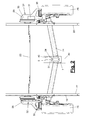
- FIG. 2 schematically illustrates the structure of such a Hilfsfahrantriebs (2), for example, in a Einachsan vonr two on both sides arranged drive units (28,29), each acting on a vehicle wheel (25). In a tandem axle or other Mehrfachachsanowskiowski more than two Drive units (28,29) may be present.
- the drive units (28, 29) each have at least one movable drive element (30), which is e.g. is designed as a rotating drive roller and by a motor (31) can be driven to rotate.
- the motor (31) may e.g. be a single or multiple controllable electric motor. In addition, any other controllable motor or drive trainings are possible.
- the drive unit (28, 29) in each case has an infeed device (32) with which the drive element (30) is moved between a retracted rest position and the in FIG. 2 shown drive position before and possibly also can be moved back.
- the drive element (30) In the drive position, the drive element (30) is pressed at a suitable location on the vehicle wheel (25) and rotates this in its driven self-rotation.
- the feed device (32) has a feed drive (33). This can be a separate drive. Alternatively, this drive can be derived from the motor (31), which then provides for the delivery and for the roller rotation.
- the feed drive (33) can be switched on and off and possibly controlled.
- the infeed motion can have any path and kinematics. This can be a linear movement or a pivoting movement with appropriate guidance. Furthermore, a kinematics with a combination of multiple rotational and / or translational motion axes is possible.
- the auxiliary drive (2) has a controller (7).
- This can be, for example, a central control for two or more drive units (28, 29).
- FIG. 2 is, for example, the arrangement of such a common control device (7) at a central location, eg at the vehicle axle.
- the control unit (7) communicates via lines or wirelessly by radio or the like. With the motor controls in the drive units (28,29).
- the controller (7) can also be accommodated in one of the auxiliary travel drives (28, 29) and combined with the local engine control unit (s).
- the auxiliary drive (2) and its one or more drive units (28,29) can be operated and controlled by an operator by means of an operating device (8).
- the operating device (8) includes an operating device (9), which is preferably designed as a remote control and can be held by the operator in the hand.
- the mobile operating device (9) has a display and one or more operating elements in the form of buttons, a joystick, touchpad or the like.
- the operating device (8) and the operating device (9) can be designed in any suitable manner. In the illustrated embodiment, they may have a configuration corresponding to DE 20 2009 005 524 U1 to have.
- the mobile control unit (9) can communicate with the controller (7) of the auxiliary drive (2) via a communication device (45) and exchange signals in both directions, in particular control and display signals.
- the communication can be wired via a cable or wirelessly by radio, infrared, ultrasound or otherwise.
- the auxiliary drive (2) has a safety device (3) for its function as a function of the operating and / or operating situation.
- the safety device (3) has a detection device (4) for detecting a relevant for the maneuvering operation and / or operating situation.
- the securing device (3) has Furthermore, a switching device (5) for releasing or blocking the auxiliary drive (2) as a whole or with respect to individual functions.
- the detection device (4) and the switching device (5) there are various design options.
- the operating situation concerns the question of where the operator and / or the mobile operating part (9) are located when the control (7) receives operating and control signals.
- the operating situation may affect the vehicle (1) on the one hand. Criteria are, for example, a trailer operation or driving operation of the trailer. During the drive, the auxiliary drive (2) should not be operated or operated. Another criterion is the clutch situation. When the mechanical coupling connection according to FIG. 1 is closed, the vehicle (1) can not be moved and ranked independently of the towing vehicle (15) by the auxiliary drive (2). The same applies to a closed equipment connection (17). Another criterion is a blocking situation of the vehicle wheels (25) or a position securing the trailer (1). As part of the maneuvering can be ensured, for example, that the trailer (1) is not moved with the parking brake (20) or that after maneuvering the auxiliary drive (2) or the drive element (30) is released without the parking position of the vehicle (1) is secured. Otherwise, the vehicle (1) could possibly set itself in motion without permission at a sloping point.
- the environment of the vehicle (1) can be a criterion for the operating situation. This applies, for example, to obstacles or danger spots in the maneuvering area. In addition, further criteria for the operating situation of the vehicle or trailer (1) are possible.
- the mentioned operating situation may alternatively or additionally relate to the situation of the auxiliary drive (2).
- a shunting operation can be prevented or, if appropriate, only carried out with restrictions.
- the safety device (3) can activate and deactivate the auxiliary drive (2) as a function of the operating and / or operating situation.
- the auxiliary traction drive (2) can be switched on altogether in operational readiness and switched off from standby.
- an operation and operation by means of the operating device (8) or the mobile control unit (9) is possible.
- operation signals or operation signals for the communication device (45) or signal noise in the environment or the like are not accepted.
- the energy supply of the auxiliary drive (2) and in particular its drive units (28, 29) or their components can be prevented.
- the safety device (3) in the deactivation phase can prevent the drive element (30) from coming into braking or driving-safety-endangering contact with the vehicle wheel (25). This is particularly important for the aforementioned team and driving operation.
- the securing device (3) can alternatively or additionally activate and deactivate individual functions of the auxiliary drive (2). This in turn can be done depending on the respective operating and / or operating situation.
- the said activation and deactivation via the switching device (5) which releases the auxiliary drive (2) or locks.
- the auxiliary drive (2) can be operated and used for maneuvering the vehicle (1).
- it can also be monitored by the securing device (3) whether such an operation actually takes place or not and how its course is. A plausibility check can also be implemented.
- Deactivation to block the auxiliary drive (2) can be situation-specific or event-dependent. It can also be time-dependent. About a timer (34) at a suitable location, in particular in the controller (7), the deactivation can take place after a period of time.
- the time span can be predetermined and possibly also changeable. The time span can be fixed and start to run when the auxiliary drive (2) is activated. On the other hand, the period of time may be coupled to an operation of the auxiliary traveling drive (2), so that its beginning is variable. If e.g. after a control or command during the period no new command is entered, the deactivation takes place.
- the activation and deactivation of the auxiliary drive (2) as a whole or of individual functions of the auxiliary drive (2) can take place via the switching device (5).
- This can for example be implemented in the controller (7). This can be done in terms of hardware and / or software.
- the switching device (5) can also be housed separately from the controller (7) and communicate with this.
- Activation and deactivation of the auxiliary traction drive (2) can in the present case e.g. by an interruption of the power supply via the switching device (5). This interrupts the deactivation of the transmission of energy to the drive units (28,29) and switches this example. de-energized.
- the drive element (30) can neither be set in rotation by the respective drive (31, 33) nor delivered to the vehicle wheel (25). It is also possible to prevent only the delivery or only the drive rotation.
- deactivating the position assurance of the trailer (1) can also be checked in the rest position when the parking position is not secured, which is e.g. by actuation of the parking brake (20) or in another verifiable manner.
- the drive element (30) remains in the drive and pressing position on the vehicle wheel (25) and prevents its rotation.
- a warning signal e.g. acoustically and / or optically output by the securing device (3).
- the safety device (3) may also alternatively or additionally comprise a signaling device (6) which outputs an audible and / or visual or other warning signal when the auxiliary drive (2) is activated and draws the operator's attention to the activation situation.
- a signaling device (6) which outputs an audible and / or visual or other warning signal when the auxiliary drive (2) is activated and draws the operator's attention to the activation situation.
- the detection device (4) is in operative connection with the switching device (5) and / or the signaling device (6).
- the detection device (4) can influence the switching device (5) and trigger its switching function.
- the detection device (4) and the switching device (5) can be arranged functionally and representationally and also locally separated. They can alternatively be combined with each other.
- the switching device (5) can in turn be in the aforementioned manner in operative connection with a controller (7) of the auxiliary drive (2). It may alternatively or additionally be in operative connection with the signaling device (6).
- the switching device (5) may also be in indirect or direct operative connection with components of the auxiliary traction drive (2), e.g. with the drive element (30) and / or the delivery device (32) and enable or disable their function.
- the switching device (5) can also be in direct or indirect operative connection with the power supply (26) and this can also be assigned directly, for example.
- the switching device (5) acts on the auxiliary drive (2) and its components located on the chassis (10).
- the energy supply (26) can be switched off in the manner described.
- the switching device (5) can influence the operability of the auxiliary drive (2) and, for this purpose, be in operative connection with the operating device (8), preferably a mobile operating part (9).
- Activation of the possibly permanently supplied with auxiliary auxiliary drive (2) is given in this case by a situation-based activation or deactivation of its operation. This in turn can be done by the Detected operating and / or operating situation dependent.
- a deactivation can, for example, be time-dependent in the manner described above.
- the switching device (5) it is possible, for example, for the switching device (5) to release the operating device (8), in particular a mobile operating part (9), with a time limit, wherein operation is possible within a fixed or dynamic time window.
- the timer (34) can be associated with the operating device (8), in particular the mobile operating part (9).
- a possibly superimposed time-dependent shutdown of the auxiliary drive (2) e.g. from the power supply (26), via its components by one or more implemented additional timers.
- the detection device (4) can detect an existing, emerging or possibly arising and relevant for shunting operation situation of the trailer (1) and / or the auxiliary drive (2).
- detection of corresponding features or signs a situation development can be detected.
- the detected parameters or features may be direct or indirect indicators of said operating situation.
- the detection device (4) can have one or more detection means (35) for detecting one or more representative features of an operating situation relevant to the maneuvering operation.
- a vehicle position in particular a driving operation or a resting state of the vehicle (1) is detected.
- a coupling situation of the vehicle (1) in particular a mechanical coupling connection or a resource connection (17) can be detected.
- a blocking situation or Braking situation of the vehicle wheels (25) can be detected.
- the detection device (4) also has one or more detection means (36) for detecting a relevant for the maneuvering operation situation. This may in particular include a location of an operator and / or a mobile control unit (9).
- the detection means (35, 36) can have at least one corresponding sensor (38, 39, 40, 41).
- the detection means (35,36) may be present individually or in combination. The same applies to their sensors (38,39,40,41), which may also be present simply or repeatedly and in any combination.
- a detection of an operating situation is e.g. possible through an operator location. In this way, it can be determined whether the operator and in particular the mobile control unit (9) are in such a position relative to the vehicle or trailer (1) that incorrect operation is at least largely precluded.
- Activation of the auxiliary drive (2) or its components and / or the operating device (8) only from the immediate vicinity of the vehicle done. In this way, it is ruled out that incorrect operation can take place in the trailer operation from the moving towing vehicle (15).
- the detection means (36) may have a sensor (41) with a switching contact (42) arranged on the outside of the vehicle (1) for operating location, wherein the switching contact (42) with the switching device (5) in FIG Active connection is and in particular connected via an electrical line.
- the switching contact (42) can according to FIG. 3 be arranged in the region of the drawbar (11) or on the structure (27).
- the switch contact (42) may require a minimum approach of the operator or the mobile control unit (9) for its operation.
- the switching contact (42) may be a non-contact contact or switch. It may in particular be a reed contact or a reed relay.
- Activation or actuation is accomplished by a contact trigger (43), e.g. is designed as a magnet and in the mobile control unit (9) is arranged. Due to the correspondingly limited magnetic flux tripping is possible only with great approximation and requires a disembarkation of the operator from the towing vehicle (15).
- the switching device (5) activated on the signal of the switching contact (42) towards the auxiliary drive (2) in the manner described above.
- Such a switching contact (42) is low-wear and sabotage gleich and operational and fail-safe. Even false triggering by children or the like can be avoided.
- mechanical toggle switches, buttons or the like are possible for activation, wherein the non-contact and a particular contact trigger requiring switching contact (42) has advantages.
- Deactivation may be via one or more timers (34) after the expiration of a predetermined period of fixed or dynamic start. This ensures that a deactivation of the auxiliary drive (2) takes place even if the operator changes his intent and disregards an operation of the auxiliary drive (2) and a shunting operation. Otherwise, in this and in the other exemplary embodiments, a deliberate deactivation by the operator by corresponding actuation of the operating device (8), in particular of the mobile control unit (9), for example by pressing a switch-off, be effected.
- any other switching contact (42) acting with a preset proximity may also be used, e.g. a proximity sensor.
- a transponder or RFID chip with a limited range can be used.
- a wireless transceiver assembly (44) may be provided on the mobile control panel (9) and on the vehicle (1) allowing operation only from the immediate vicinity of the vehicle (1) or one or more particular directions, in which case a malfunction is excluded from the towing vehicle (15) or from another point.
- the transmitter / receiver arrangement (44) may be e.g. Radio modules with a limited range, wherein the one module on the mobile control unit (9) and the other module on suitable and e.g. central point of the vehicle (1), in particular in the vicinity of the controller (7) or on a drive unit (28,29) is arranged.
- the arrangement (44) may consist of a straightening path with light beams, sound waves or the like. Media with directional propagation, in particular with infrared light.
- the transmitter can be arranged, for example, on the operating part (9), wherein one or more receivers are arranged on one or more suitable vehicle locations, eg laterally on the body (27) are.
- the transmitter / receiver arrangement (44) can be used independently of the remote control and the transmission of the control signals.
- an operator location via the communication device (45) is possible, e.g. also has a direction specification or a range limit for the transmission of the operating signals to the exclusion of towing vehicle (15).
- the activation of the auxiliary traction drive (2) can be achieved via actuation of operating elements, e.g. Switches, joystick or the like. Of the mobile control unit (9) happen. Deactivation can again be time-dependent.
- FIG. 4 and 5 illustrate design options for the detection means (35).
- the vehicle position in particular a driving operation or a resting state of the vehicle (1)
- the sensor (38) can eg according to FIG. 4 have a in the range of at least one vehicle wheel (25) arranged motion detector. This registers rotational movements of the vehicle wheel (25) and allows activation of the auxiliary drive (2) only when the vehicle (1).
- a motion detector or rotary encoder can be arranged on the vehicle wheel (25), on the chassis (10) or on a drive unit (28, 29). It may be, for example, a Refelexlichtaster, similar to computer mice, a magnet switch as speedometer or the like. Act.
- the sensor system (38) may comprise a motion detector arranged on the chassis (10), on a drive unit (28, 29) or the like, which may be e.g. is designed as an acceleration sensor and detects the possible presence of a driving operation. If necessary, the sensor system (38) can also be used for other purposes, e.g. for the aforementioned rolling brake (46). In this case, it is alternatively possible to resort to sensors which may be present there and to additionally use these for the safety device (3). The sensors or detectors can be present multiple times and in any combination.
- the detection means (35) may alternatively or additionally comprise a sensor system (39) for the coupling situation of the vehicle (1), in particular for a mechanical coupling connection of the trailer (1) to the towing vehicle (15).
- FIG. 5 clarifies this version.
- the sensor system (39) can be designed, for example, as a contact detector or as a position detector on the trailer coupling (12).
- a contact detector can also be arranged on a detent display and detect its function.
- the lock indicator can, for example, according to the DE 94 12 514 U1 or be formed in another way.
- a position detector may for example be arranged on the clutch lever (13) and detect its inclination or end position, provided that this is significant for an opening or closing position of the clutch lever (13) and the trailer coupling (12).
- the sensor system (39) can furthermore be integrated into the plug-in coupling of the equipment connection (17) and electrically detect a coupling situation via a closed ground contact or in some other way.
- the detection means (35) can have a sensor system (40) for the movability of the vehicle (1), in particular for the surrounding situation and / or the braking device (18).
- the sensor (40) for example, a tilt detector and / or a position detector on the handbrake lever (21). This can be used to detect whether the hand brake lever (21) is in the clamping position or in the release position. Further, other types and arrangements of detectors for detecting a handbrake actuation are possible.
- Activation and deactivation of the auxiliary drive (2) can be event-related in these cases.
- an operating or control command e.g. Switching on or for delivering the drive element (30) given.
- the switching device (5) then interrogates the detection means (35) and activates the auxiliary drive drive (2), for example when signaling an operating situation suitable for shunting operation. by energizing the feed drive (33).
- a deactivation can take place on the basis of an operating or control command for resetting the drive element (30) by autonomous shutdown after completion of the reset and by the switching device (5) or by automatic shutdown of the auxiliary drive (2). If the reset is forgotten, the drive element (30) remains in the working position and prevents or hampers, at least noticeably, a trailer movement and, in particular, driving off the trailer, whereby possibly also issuing a warning signal. This causes the Operator to enter a default command. Until such a reset command the auxiliary drive (22) remains activated if necessary. If necessary, coupling of the trailer (1) to a towing vehicle (15) can also be detected with the detection means (35) and then the auxiliary drive drive (2) can be deactivated by the switching device (5).
- the sensor (40) can also be used to control individual functions of the auxiliary drive (2).
- a first activation of the auxiliary drive (2) and also a delivery of the drive element (30) to the vehicle wheel (25) is only possible when the parking brake (20), for example when the handbrake lever (21) is applied.
- the actuated parking brake (20) is an indicator for the vehicle position and signals that the vehicle (1) is in rest or parking position and not in moving vehicle operation.
- An activation of the rotary drive or motor (31) for the drive roller (30) is possible only at a later time after releasing the parking brake (20) or the handbrake lever (21), which in turn is detected and reported by the sensor (40).
- the drive element (30) remains in the drive position on the vehicle wheel (25).
- the drive element (30) remains in contact with the vehicle wheel (25) and acts by self-locking in the Drive train or otherwise as a braking means for the vehicle (1), which prevents any unwanted movement of the vehicle (1). From this situation, a time-dependent deactivation of the auxiliary drive (2) can take place, wherein possibly at the same time a warning or warning signal for the operator via the signaling device (6) or otherwise issued. Even in the deactivation phase, the drive element (30) blocks the vehicle wheel (25).
- a renewed activation of the auxiliary drive (2) takes place only when the parking brake (20) or the brake lever (21). Again, a warning or warning signal can be issued. Subsequently, the pre-pictured maneuvering operation can be recorded, wherein the delivery of the drive element (30) has already taken place.
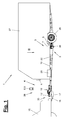
- FIG. 6 shows in a broken plan view of a front drawbar area with a drawbar hood (50), which covers the front connecting portion of the drawbar spars (11).
- the drawbar cover (50) is also in FIG. 5 shown.
- a display (47,48) is arranged, for example, a status display can represent and / or which can emit the aforementioned warning signals.
- the display (47, 48) can have one or more display elements (49). These may be, for example, optical display elements, in particular LEDs, and / or acoustic or other display elements, which may be supplemented with identification aids, eg, a label.
- the aforementioned switching contact (42) of the detection device (4) or of the detection means (36) can also be arranged.
- the one display (47) can be assigned to a roll-stop brake (46) and can indicate its functional and operational readiness or possibly malfunctions in the brake area, eg by a color change.
- the roll brake (46) can for this purpose have a suitable diagnostic and monitoring device for detecting and signaling operating conditions and possible malfunctions. If the skid brake (46) locks and brakes the wheel brakes or there is another brake blockage, the operator may be warned via the display (47) that he should first clear the blockage before actuating the auxiliary traction drive (2) ,
- the aforementioned monitoring device (37) of the auxiliary drive (2) may also have such a diagnostic and monitoring function for detecting operating conditions, positions, disturbances, etc.
- a correct and completed execution of the operating commands for example the delivery command or the withdrawal command for the drive element (30) can be detected.
- the capture of the commanded or intended position of the drive element (30) can be detected. This may, for example, relate to the assumption of the retraction position, because the trailer (1) with the auxiliary drive (2) supplied should not be towed by a towing vehicle.
- An arrangement of the display (48) in the front drawbar area is favorable, because it is noticed when coupling.
- the motors or drive elements in the drive units (28,29) and other functional parts of the auxiliary drive (2) can be checked for their function and operational readiness and signaled by a corresponding, possibly multi-part display (48).
- the display (48) associated with the auxiliary drive (2) may also be a status indicator indicating operational readiness or malfunction, e.g. signaled by a color change from green to red.
- the displays (47, 48) and the switching contact (42) can be arranged together on a support plate or another holder. You are in an easily visible and accessible area for the operator at the front end of the vehicle. Alternatively, they may also be arranged at another suitable location of the vehicle (1).
- the senor (40) for the mobility of the vehicle (1) one or more on the chassis (10) or on the structure (27) arranged ambient detectors have, for example, are designed as proximity sensors and the possible obstacles in the range of motion of the vehicle (1) during maneuvering. These may be similar to parking sensors in motor vehicles designed and arranged and output a visual, audible or other warning signal on the vehicle (1) and / or the operating device (8) or the control panel (9) when the distance between the vehicle (1). and an obstacle becomes too small. This facilitates maneuvering even in difficult visibility conditions.
- the described components of the securing device (3) in particular the sensor systems (38, 39, 40, 41) can be present individually or multiply and in any desired combination. They allow the query of a single situation criterion or of several criteria for a more complex situation detection.
- the sensor systems (38, 39, 40, 41) can be suitably in operative connection with the switching device (5) and / or the signal device (6), in particular in electrical signal connection.
- the features of the embodiments can be combined with each other in any way and / or reversed. This applies in particular to the design of the detection device (4) and its function.
- the detection possibilities are manifold and can be used individually or in any combination.
- the auxiliary drive (2) may have in the claimed embodiment, a safety device (3) for its function depending on the operating situation. The dependency may additionally or alternatively be given by the operating situation of the vehicle (1) and / or the auxiliary drive drive (2).
- the detection means (35, 36) and their sensors (38, 39, 40, 41) described by way of example can also be configured differently and used individually or in combination.
- the safety device (3) may have a signaling device (6) for signaling a release of the auxiliary drive (2), wherein optionally the detection device (4) is in operative connection with the switching device (5) and / or the signaling device (6).
- the switching device (5) can also be in operative connection with a signaling device (6) and / or in operative connection with a power supply (26) of the auxiliary drive (2) and / or in operative connection with an operating device (8).
- the securing device (3) and / or the auxiliary drive (2) may have a timing element (34), which may be in operative connection with the switching device (5).
- the safety device (3) can control the activability of the auxiliary drive (2) time-dependent.
- the switching device (5) can release the auxiliary drive drive (2) and / or the operating device (8), in particular a mobile operating part (9), with a time limit.
Landscapes
- Engineering & Computer Science (AREA)
- Transportation (AREA)
- Mechanical Engineering (AREA)
- Chemical & Material Sciences (AREA)
- Combustion & Propulsion (AREA)
- Regulating Braking Force (AREA)
- Arrangement And Mounting Of Devices That Control Transmission Of Motive Force (AREA)
Applications Claiming Priority (1)
| Application Number | Priority Date | Filing Date | Title |
|---|---|---|---|
| DE202009005185U DE202009005185U1 (de) | 2009-08-26 | 2009-08-26 | Hilfsantrieb |
Publications (4)
| Publication Number | Publication Date |
|---|---|
| EP2289776A2 true EP2289776A2 (fr) | 2011-03-02 |
| EP2289776A3 EP2289776A3 (fr) | 2012-03-28 |
| EP2289776B1 EP2289776B1 (fr) | 2017-01-11 |
| EP2289776B2 EP2289776B2 (fr) | 2022-07-20 |
Family
ID=43031491
Family Applications (1)
| Application Number | Title | Priority Date | Filing Date |
|---|---|---|---|
| EP10174200.5A Active EP2289776B2 (fr) | 2009-08-26 | 2010-08-26 | Dispositif d'entraînement secondaire pour une remorque |
Country Status (2)
| Country | Link |
|---|---|
| EP (1) | EP2289776B2 (fr) |
| DE (1) | DE202009005185U1 (fr) |
Cited By (3)
| Publication number | Priority date | Publication date | Assignee | Title |
|---|---|---|---|---|
| DE202012006085U1 (de) | 2012-05-29 | 2012-07-12 | Truma Gerätetechnik GmbH & Co. KG | Anhänger-Rangierantrieb mit signalfarbener Abdeckung |
| EP3290308A3 (fr) * | 2016-08-19 | 2018-07-18 | Reich GmbH Regel- und Sicherheitstechnik | Dispositif de fixation et d'appui et remorque |
| WO2023156564A1 (fr) * | 2022-02-16 | 2023-08-24 | Frank Heil | Aide à la fixation pour remorque de véhicule |
Families Citing this family (18)
| Publication number | Priority date | Publication date | Assignee | Title |
|---|---|---|---|---|
| DE102011115378A1 (de) * | 2011-10-10 | 2013-04-11 | Losch Airport Equipment Gmbh | Vorrichtung zur sicheren Annäherung eines Wasser-/Fäkalien-Fahrzeugs an ein Flugzeug |
| DE102011120651A1 (de) * | 2011-12-09 | 2013-06-13 | Westfalia-Automotive Gmbh | Steuergerät und Anhängekupplung zur Kommunikation mit einem Bediengerät |
| DE202012010077U1 (de) * | 2012-10-22 | 2012-11-13 | Truma Gerätetechnik GmbH & Co. KG | Rangierantrieb mit Sensor für Deichselstecker |
| DE202012010074U1 (de) * | 2012-10-22 | 2012-11-12 | Truma Gerätetechnik GmbH & Co. KG | Rangierantrieb mit Zusatzbremsmodul |
| GB2514782A (en) * | 2013-06-03 | 2014-12-10 | Purple Line Ltd | Integrated drive unit for a trailer |
| DE202013103040U1 (de) | 2013-07-09 | 2014-10-10 | Alois Kober Gmbh | Antriebseinheit für einen Hilfsfahrantrieb |
| DE202014103988U1 (de) * | 2014-08-26 | 2015-11-27 | Carman Enterprise Co., Ltd. | Kit für die kabellose Steuerung eines Rangierantriebssystems für ein Fahrzeug, Rangierantriebssystem sowie Fahrzeug |
| DE202016100947U1 (de) * | 2016-02-23 | 2017-05-24 | Alois Kober Gmbh | Stabilisierungseinrichtung |
| EP3379222B1 (fr) | 2017-03-22 | 2020-12-30 | Methode Electronics Malta Ltd. | Ensemble de capteur à base magnétoélastique |
| US11084342B2 (en) | 2018-02-27 | 2021-08-10 | Methode Electronics, Inc. | Towing systems and methods using magnetic field sensing |
| US11491832B2 (en) | 2018-02-27 | 2022-11-08 | Methode Electronics, Inc. | Towing systems and methods using magnetic field sensing |
| US11135882B2 (en) | 2018-02-27 | 2021-10-05 | Methode Electronics, Inc. | Towing systems and methods using magnetic field sensing |
| US11221262B2 (en) | 2018-02-27 | 2022-01-11 | Methode Electronics, Inc. | Towing systems and methods using magnetic field sensing |
| EP3758959A4 (fr) | 2018-02-27 | 2022-03-09 | Methode Electronics, Inc. | Systèmes et procédés de remorquage utilisant la détection magnétique |
| NL2020647B1 (nl) * | 2018-03-22 | 2019-10-02 | Wagenbouw Hapert B V | Aanhangwagen voorzien van ondersteuning bij handmatig verplaatsen |
| DE202018106549U1 (de) | 2018-11-19 | 2020-03-12 | Alois Kober Gmbh | Elektrische Antriebs- und Bremseinrichtung |
| DE102019205156A1 (de) * | 2019-04-10 | 2020-10-15 | Volkswagen Aktiengesellschaft | Verfahren zur Fahrstabilisierung eines Anhängers |
| AT17376U1 (de) * | 2021-03-30 | 2022-02-15 | Varch Wolfgang | Anhänger für ein Kraftfahrzeug |
Citations (8)
| Publication number | Priority date | Publication date | Assignee | Title |
|---|---|---|---|---|
| DE9412514U1 (de) | 1994-08-03 | 1995-06-14 | Kober Ag | Kugelkopf-Anhängerkupplung |
| EP1447312A1 (fr) | 2003-02-13 | 2004-08-18 | Reich KG | Dispositif de manoeuvre pour véhicules non motorisés |
| EP1598249A1 (fr) | 2004-05-19 | 2005-11-23 | Al-Ko Kober Ag | Frein anti-devers pour remorques |
| DE202006004679U1 (de) | 2006-03-23 | 2006-06-01 | Knott Gmbh | Bremseinrichtung zur Stabilisierung von Fahrzeuganhängern bei Schlingerbewegungen |
| EP1836085B1 (fr) | 2004-12-06 | 2008-01-23 | Truma Gerätetechnik GmbH & Co. KG | Commande auxiliaire pour une remorque |
| EP2022688A2 (fr) | 2007-08-06 | 2009-02-11 | BPW Fahrzeugtechnik GmbH & Co. KG | Système de freinage supplémentaire et dispositif de déclenchement pour systèmes de freinage supplémentaires pour l'actionnement de freins de remorques à inertie |
| EP2022654A2 (fr) | 2007-08-06 | 2009-02-11 | BPW Fahrzeugtechnik GmbH & Co. KG | Système de frein supplémentaire et procédé d'actionnement de freins de véhicule |
| DE202009005524U1 (de) | 2008-06-25 | 2009-07-02 | Al-Ko Kober Ag | Hilfsantrieb |
Family Cites Families (12)
| Publication number | Priority date | Publication date | Assignee | Title |
|---|---|---|---|---|
| DE3871543T2 (de) * | 1987-02-12 | 1993-01-28 | Sabro Ltd | Manoevriervorrichtung fuer anhaenger. |
| DE3736788A1 (de) | 1987-10-30 | 1989-05-11 | Gerhard Lev | Hilfsantrieb fuer fahrzeuge |
| DE19614752A1 (de) | 1996-04-16 | 1997-10-02 | Harald Schmieder | Hilfsantrieb für Wohnwagen oder Anhänger |
| FR2786456B1 (fr) | 1998-11-27 | 2001-01-12 | Renovmag Equipement | Dispositif facilitant les deplacements et les manoeuvres des vehicules a deux roues directrices du type remorques notamment |
| NL1027925C2 (nl) * | 2004-12-30 | 2006-07-04 | Reich Kg | Hulpaandrijving en voertuig voorzien van een hulpaandrijving. |
| DE102005006574B3 (de) | 2005-02-11 | 2006-09-21 | Barthelt, Hans-Peter, Dipl.-Ing. | Rollstuhl mit Fernbedienung |
| EP1752365B1 (fr) | 2005-08-09 | 2010-09-08 | Truma Gerätetechnik GmbH & Co. KG | Dispositif de sécurité pour un entraînement auxiliaire de remorque |
| NL1029805C2 (nl) | 2005-08-25 | 2007-02-27 | Reich Kg | Inrichting en werkwijze voor het manoeuvreren van een losgekoppelde aanhanger. |
| JP4037429B2 (ja) * | 2005-08-29 | 2008-01-23 | 三菱電機株式会社 | 駐車補助装置 |
| GB2435455A (en) | 2006-02-28 | 2007-08-29 | James Richard Yates | Trailer manoeuvring system |
| NL1031455C2 (nl) * | 2006-03-28 | 2007-10-01 | Reich Kg | Hulpaandrijving voor een aanhanger. |
| DE502006006451D1 (de) | 2006-08-07 | 2010-04-29 | Truma Geraetetechnik Gmbh & Co | Rangiervorrichtung für Anhänger mit eigenem Hilfsantrieb |
-
2009
- 2009-08-26 DE DE202009005185U patent/DE202009005185U1/de not_active Expired - Lifetime
-
2010
- 2010-08-26 EP EP10174200.5A patent/EP2289776B2/fr active Active
Patent Citations (8)
| Publication number | Priority date | Publication date | Assignee | Title |
|---|---|---|---|---|
| DE9412514U1 (de) | 1994-08-03 | 1995-06-14 | Kober Ag | Kugelkopf-Anhängerkupplung |
| EP1447312A1 (fr) | 2003-02-13 | 2004-08-18 | Reich KG | Dispositif de manoeuvre pour véhicules non motorisés |
| EP1598249A1 (fr) | 2004-05-19 | 2005-11-23 | Al-Ko Kober Ag | Frein anti-devers pour remorques |
| EP1836085B1 (fr) | 2004-12-06 | 2008-01-23 | Truma Gerätetechnik GmbH & Co. KG | Commande auxiliaire pour une remorque |
| DE202006004679U1 (de) | 2006-03-23 | 2006-06-01 | Knott Gmbh | Bremseinrichtung zur Stabilisierung von Fahrzeuganhängern bei Schlingerbewegungen |
| EP2022688A2 (fr) | 2007-08-06 | 2009-02-11 | BPW Fahrzeugtechnik GmbH & Co. KG | Système de freinage supplémentaire et dispositif de déclenchement pour systèmes de freinage supplémentaires pour l'actionnement de freins de remorques à inertie |
| EP2022654A2 (fr) | 2007-08-06 | 2009-02-11 | BPW Fahrzeugtechnik GmbH & Co. KG | Système de frein supplémentaire et procédé d'actionnement de freins de véhicule |
| DE202009005524U1 (de) | 2008-06-25 | 2009-07-02 | Al-Ko Kober Ag | Hilfsantrieb |
Cited By (4)
| Publication number | Priority date | Publication date | Assignee | Title |
|---|---|---|---|---|
| DE202012006085U1 (de) | 2012-05-29 | 2012-07-12 | Truma Gerätetechnik GmbH & Co. KG | Anhänger-Rangierantrieb mit signalfarbener Abdeckung |
| EP3290308A3 (fr) * | 2016-08-19 | 2018-07-18 | Reich GmbH Regel- und Sicherheitstechnik | Dispositif de fixation et d'appui et remorque |
| EP3795460A1 (fr) * | 2016-08-19 | 2021-03-24 | Reich GmbH Regel- und Sicherheitstechnik | Dispositif de fixation et d'appui et remorque |
| WO2023156564A1 (fr) * | 2022-02-16 | 2023-08-24 | Frank Heil | Aide à la fixation pour remorque de véhicule |
Also Published As
| Publication number | Publication date |
|---|---|
| EP2289776B1 (fr) | 2017-01-11 |
| EP2289776A3 (fr) | 2012-03-28 |
| EP2289776B2 (fr) | 2022-07-20 |
| DE202009005185U1 (de) | 2011-01-20 |
Similar Documents
| Publication | Publication Date | Title |
|---|---|---|
| EP2289776B1 (fr) | Dispositif d'entraînement secondaire pour une remorque | |
| EP2602134B1 (fr) | Appareil de commande pour un attelage et attelage en étant équipé | |
| EP2899101B1 (fr) | Pivot central avec capteur | |
| EP1998965B1 (fr) | Boîtier de connexion | |
| EP1658211B1 (fr) | Systeme facilitant les manoeuvres d'un vehicule automobile | |
| EP2928734B1 (fr) | Procédé, système et dispositif de commande, destinés à actionner un organe d'immobilisation pour une remorque | |
| DE102009012253A1 (de) | Verfahren zur Unterstützung beim Rückwärtsfahren eines Gespanns aus Zugfahrzeug mit Anhänger | |
| EP1874616B1 (fr) | Procede et dispositif pour atteler et deteler des semi-remorques entierement automatiquement | |
| DE202016101279U1 (de) | Antriebseinheit | |
| EP2921325A1 (fr) | Procédé et dispositif de télécommande d'un véhicule automobile, système de commande de véhicule électronique et véhicule automobile en étant équipé | |
| DE102013106875B4 (de) | EPI-Modul | |
| DE102016115873A1 (de) | Schlingerbremseinrichtung | |
| DE102010035299A1 (de) | Verfahren und Vorrichtung zum Bewegen eines Anhängers | |
| DE102011003231A1 (de) | Verfahren zum automatischen Durchführen eines Fahrmanövers | |
| WO2005108194A1 (fr) | Procede pour enlever et mettre en place une semi-remorque | |
| DE102019117123A1 (de) | System und verfahren zum positionieren eines fahrzeugs mit reduzierter variation | |
| DE102008014130A1 (de) | Verfahren zur Steuerung eines Parkassistenzsystems für Fahrzeuge und Parkassistenzsystem | |
| EP3568732B1 (fr) | Procédé d'actionnement d'un système de sécurité pour un véhicule automobile et système de sécurité | |
| DE102019132030A1 (de) | Modulare Anhängerluftversorgungseinrichtung, entsprechend ausgestatteter Anhänger sowie Verfahren zur Steuerung der Druckversorgung eines Anhängers | |
| EP2922740A1 (fr) | Procédé et dispositif de commande d'un système de surveillance de l'espace arrière d'un ensemble de véhicules | |
| DE102020119506A1 (de) | Überwachungseinrichtung und Überwachungsverfahren | |
| DE102021118755A1 (de) | Nutzfahrzeug mit einer Schnittstelle zum Verbinden mit einem Notsteuergerät und entsprechendes Notsteuergerät | |
| DE102022110612A1 (de) | Freizeitfahrzeug, Freizeitanhänger, Anordnung zur Vorgabe von Abstellplätzen für Freizeitanhänger sowie System und Verfahren für einen Freizeitanhänger | |
| EP3988350A1 (fr) | Dispositif de fixation et de libération d'une remorque de véhicule et système pourvu de dispositif et remorque de véhicule | |
| EP2239160A1 (fr) | Système d'assistance destiné à avertir le conducteur de la présence d'obstacles |
Legal Events
| Date | Code | Title | Description |
|---|---|---|---|
| PUAI | Public reference made under article 153(3) epc to a published international application that has entered the european phase |
Free format text: ORIGINAL CODE: 0009012 |
|
| AK | Designated contracting states |
Kind code of ref document: A2 Designated state(s): AL AT BE BG CH CY CZ DE DK EE ES FI FR GB GR HR HU IE IS IT LI LT LU LV MC MK MT NL NO PL PT RO SE SI SK SM TR |
|
| AX | Request for extension of the european patent |
Extension state: BA ME RS |
|
| PUAL | Search report despatched |
Free format text: ORIGINAL CODE: 0009013 |
|
| AK | Designated contracting states |
Kind code of ref document: A3 Designated state(s): AL AT BE BG CH CY CZ DE DK EE ES FI FR GB GR HR HU IE IS IT LI LT LU LV MC MK MT NL NO PL PT RO SE SI SK SM TR |
|
| AX | Request for extension of the european patent |
Extension state: BA ME RS |
|
| RIC1 | Information provided on ipc code assigned before grant |
Ipc: B62D 59/04 20060101AFI20120221BHEP |
|
| 17P | Request for examination filed |
Effective date: 20120927 |
|
| 17Q | First examination report despatched |
Effective date: 20131114 |
|
| RAP1 | Party data changed (applicant data changed or rights of an application transferred) |
Owner name: ALOIS KOBER GMBH |
|
| GRAP | Despatch of communication of intention to grant a patent |
Free format text: ORIGINAL CODE: EPIDOSNIGR1 |
|
| INTG | Intention to grant announced |
Effective date: 20160803 |
|
| STAA | Information on the status of an ep patent application or granted ep patent |
Free format text: STATUS: GRANT OF PATENT IS INTENDED |
|
| GRAS | Grant fee paid |
Free format text: ORIGINAL CODE: EPIDOSNIGR3 |
|
| GRAA | (expected) grant |
Free format text: ORIGINAL CODE: 0009210 |
|
| STAA | Information on the status of an ep patent application or granted ep patent |
Free format text: STATUS: THE PATENT HAS BEEN GRANTED |
|
| AK | Designated contracting states |
Kind code of ref document: B1 Designated state(s): AL AT BE BG CH CY CZ DE DK EE ES FI FR GB GR HR HU IE IS IT LI LT LU LV MC MK MT NL NO PL PT RO SE SI SK SM TR |
|
| REG | Reference to a national code |
Ref country code: GB Ref legal event code: FG4D Free format text: NOT ENGLISH |
|
| REG | Reference to a national code |
Ref country code: CH Ref legal event code: EP |
|
| REG | Reference to a national code |
Ref country code: AT Ref legal event code: REF Ref document number: 860976 Country of ref document: AT Kind code of ref document: T Effective date: 20170115 |
|
| REG | Reference to a national code |
Ref country code: IE Ref legal event code: FG4D Free format text: LANGUAGE OF EP DOCUMENT: GERMAN |
|
| REG | Reference to a national code |
Ref country code: DE Ref legal event code: R096 Ref document number: 502010013022 Country of ref document: DE |
|
| REG | Reference to a national code |
Ref country code: LT Ref legal event code: MG4D |
|
| REG | Reference to a national code |
Ref country code: NL Ref legal event code: MP Effective date: 20170111 |
|
| PG25 | Lapsed in a contracting state [announced via postgrant information from national office to epo] |
Ref country code: NL Free format text: LAPSE BECAUSE OF FAILURE TO SUBMIT A TRANSLATION OF THE DESCRIPTION OR TO PAY THE FEE WITHIN THE PRESCRIBED TIME-LIMIT Effective date: 20170111 |
|
| PG25 | Lapsed in a contracting state [announced via postgrant information from national office to epo] |
Ref country code: FI Free format text: LAPSE BECAUSE OF FAILURE TO SUBMIT A TRANSLATION OF THE DESCRIPTION OR TO PAY THE FEE WITHIN THE PRESCRIBED TIME-LIMIT Effective date: 20170111 Ref country code: HR Free format text: LAPSE BECAUSE OF FAILURE TO SUBMIT A TRANSLATION OF THE DESCRIPTION OR TO PAY THE FEE WITHIN THE PRESCRIBED TIME-LIMIT Effective date: 20170111 Ref country code: IS Free format text: LAPSE BECAUSE OF FAILURE TO SUBMIT A TRANSLATION OF THE DESCRIPTION OR TO PAY THE FEE WITHIN THE PRESCRIBED TIME-LIMIT Effective date: 20170511 Ref country code: NO Free format text: LAPSE BECAUSE OF FAILURE TO SUBMIT A TRANSLATION OF THE DESCRIPTION OR TO PAY THE FEE WITHIN THE PRESCRIBED TIME-LIMIT Effective date: 20170411 Ref country code: GR Free format text: LAPSE BECAUSE OF FAILURE TO SUBMIT A TRANSLATION OF THE DESCRIPTION OR TO PAY THE FEE WITHIN THE PRESCRIBED TIME-LIMIT Effective date: 20170412 Ref country code: LT Free format text: LAPSE BECAUSE OF FAILURE TO SUBMIT A TRANSLATION OF THE DESCRIPTION OR TO PAY THE FEE WITHIN THE PRESCRIBED TIME-LIMIT Effective date: 20170111 |
|
| REG | Reference to a national code |
Ref country code: FR Ref legal event code: PLFP Year of fee payment: 8 |
|
| PG25 | Lapsed in a contracting state [announced via postgrant information from national office to epo] |
Ref country code: LV Free format text: LAPSE BECAUSE OF FAILURE TO SUBMIT A TRANSLATION OF THE DESCRIPTION OR TO PAY THE FEE WITHIN THE PRESCRIBED TIME-LIMIT Effective date: 20170111 Ref country code: ES Free format text: LAPSE BECAUSE OF FAILURE TO SUBMIT A TRANSLATION OF THE DESCRIPTION OR TO PAY THE FEE WITHIN THE PRESCRIBED TIME-LIMIT Effective date: 20170111 Ref country code: SE Free format text: LAPSE BECAUSE OF FAILURE TO SUBMIT A TRANSLATION OF THE DESCRIPTION OR TO PAY THE FEE WITHIN THE PRESCRIBED TIME-LIMIT Effective date: 20170111 Ref country code: PL Free format text: LAPSE BECAUSE OF FAILURE TO SUBMIT A TRANSLATION OF THE DESCRIPTION OR TO PAY THE FEE WITHIN THE PRESCRIBED TIME-LIMIT Effective date: 20170111 Ref country code: BG Free format text: LAPSE BECAUSE OF FAILURE TO SUBMIT A TRANSLATION OF THE DESCRIPTION OR TO PAY THE FEE WITHIN THE PRESCRIBED TIME-LIMIT Effective date: 20170411 Ref country code: PT Free format text: LAPSE BECAUSE OF FAILURE TO SUBMIT A TRANSLATION OF THE DESCRIPTION OR TO PAY THE FEE WITHIN THE PRESCRIBED TIME-LIMIT Effective date: 20170511 |
|
| REG | Reference to a national code |
Ref country code: DE Ref legal event code: R026 Ref document number: 502010013022 Country of ref document: DE |
|
| PLBI | Opposition filed |
Free format text: ORIGINAL CODE: 0009260 |
|
| PG25 | Lapsed in a contracting state [announced via postgrant information from national office to epo] |
Ref country code: IT Free format text: LAPSE BECAUSE OF FAILURE TO SUBMIT A TRANSLATION OF THE DESCRIPTION OR TO PAY THE FEE WITHIN THE PRESCRIBED TIME-LIMIT Effective date: 20170111 Ref country code: RO Free format text: LAPSE BECAUSE OF FAILURE TO SUBMIT A TRANSLATION OF THE DESCRIPTION OR TO PAY THE FEE WITHIN THE PRESCRIBED TIME-LIMIT Effective date: 20170111 Ref country code: CZ Free format text: LAPSE BECAUSE OF FAILURE TO SUBMIT A TRANSLATION OF THE DESCRIPTION OR TO PAY THE FEE WITHIN THE PRESCRIBED TIME-LIMIT Effective date: 20170111 Ref country code: EE Free format text: LAPSE BECAUSE OF FAILURE TO SUBMIT A TRANSLATION OF THE DESCRIPTION OR TO PAY THE FEE WITHIN THE PRESCRIBED TIME-LIMIT Effective date: 20170111 Ref country code: SK Free format text: LAPSE BECAUSE OF FAILURE TO SUBMIT A TRANSLATION OF THE DESCRIPTION OR TO PAY THE FEE WITHIN THE PRESCRIBED TIME-LIMIT Effective date: 20170111 |
|
| PLAX | Notice of opposition and request to file observation + time limit sent |
Free format text: ORIGINAL CODE: EPIDOSNOBS2 |
|
| 26 | Opposition filed |
Opponent name: TRUMA GERAETETECHNIK GMBH & CO. KG Effective date: 20171011 |
|
| PG25 | Lapsed in a contracting state [announced via postgrant information from national office to epo] |
Ref country code: SM Free format text: LAPSE BECAUSE OF FAILURE TO SUBMIT A TRANSLATION OF THE DESCRIPTION OR TO PAY THE FEE WITHIN THE PRESCRIBED TIME-LIMIT Effective date: 20170111 Ref country code: DK Free format text: LAPSE BECAUSE OF FAILURE TO SUBMIT A TRANSLATION OF THE DESCRIPTION OR TO PAY THE FEE WITHIN THE PRESCRIBED TIME-LIMIT Effective date: 20170111 |
|
| PG25 | Lapsed in a contracting state [announced via postgrant information from national office to epo] |
Ref country code: SI Free format text: LAPSE BECAUSE OF FAILURE TO SUBMIT A TRANSLATION OF THE DESCRIPTION OR TO PAY THE FEE WITHIN THE PRESCRIBED TIME-LIMIT Effective date: 20170111 |
|
| PLAF | Information modified related to communication of a notice of opposition and request to file observations + time limit |
Free format text: ORIGINAL CODE: EPIDOSCOBS2 |
|
| REG | Reference to a national code |
Ref country code: CH Ref legal event code: PL |
|
| PG25 | Lapsed in a contracting state [announced via postgrant information from national office to epo] |
Ref country code: MC Free format text: LAPSE BECAUSE OF FAILURE TO SUBMIT A TRANSLATION OF THE DESCRIPTION OR TO PAY THE FEE WITHIN THE PRESCRIBED TIME-LIMIT Effective date: 20170111 |
|
| PG25 | Lapsed in a contracting state [announced via postgrant information from national office to epo] |
Ref country code: LI Free format text: LAPSE BECAUSE OF NON-PAYMENT OF DUE FEES Effective date: 20170831 Ref country code: CH Free format text: LAPSE BECAUSE OF NON-PAYMENT OF DUE FEES Effective date: 20170831 |
|
| PLBB | Reply of patent proprietor to notice(s) of opposition received |
Free format text: ORIGINAL CODE: EPIDOSNOBS3 |
|
| REG | Reference to a national code |
Ref country code: IE Ref legal event code: MM4A |
|
| REG | Reference to a national code |
Ref country code: BE Ref legal event code: MM Effective date: 20170831 |
|
| PG25 | Lapsed in a contracting state [announced via postgrant information from national office to epo] |
Ref country code: LU Free format text: LAPSE BECAUSE OF NON-PAYMENT OF DUE FEES Effective date: 20170826 |
|
| REG | Reference to a national code |
Ref country code: FR Ref legal event code: PLFP Year of fee payment: 9 |
|
| PG25 | Lapsed in a contracting state [announced via postgrant information from national office to epo] |
Ref country code: IE Free format text: LAPSE BECAUSE OF NON-PAYMENT OF DUE FEES Effective date: 20170826 |
|
| PG25 | Lapsed in a contracting state [announced via postgrant information from national office to epo] |
Ref country code: BE Free format text: LAPSE BECAUSE OF NON-PAYMENT OF DUE FEES Effective date: 20170831 |
|
| PG25 | Lapsed in a contracting state [announced via postgrant information from national office to epo] |
Ref country code: MT Free format text: LAPSE BECAUSE OF FAILURE TO SUBMIT A TRANSLATION OF THE DESCRIPTION OR TO PAY THE FEE WITHIN THE PRESCRIBED TIME-LIMIT Effective date: 20170111 |
|
| REG | Reference to a national code |
Ref country code: AT Ref legal event code: MM01 Ref document number: 860976 Country of ref document: AT Kind code of ref document: T Effective date: 20170826 |
|
| PG25 | Lapsed in a contracting state [announced via postgrant information from national office to epo] |
Ref country code: AT Free format text: LAPSE BECAUSE OF NON-PAYMENT OF DUE FEES Effective date: 20170826 |
|
| PG25 | Lapsed in a contracting state [announced via postgrant information from national office to epo] |
Ref country code: HU Free format text: LAPSE BECAUSE OF FAILURE TO SUBMIT A TRANSLATION OF THE DESCRIPTION OR TO PAY THE FEE WITHIN THE PRESCRIBED TIME-LIMIT; INVALID AB INITIO Effective date: 20100826 |
|
| APBM | Appeal reference recorded |
Free format text: ORIGINAL CODE: EPIDOSNREFNO |
|
| APBP | Date of receipt of notice of appeal recorded |
Free format text: ORIGINAL CODE: EPIDOSNNOA2O |
|
| APAH | Appeal reference modified |
Free format text: ORIGINAL CODE: EPIDOSCREFNO |
|
| PG25 | Lapsed in a contracting state [announced via postgrant information from national office to epo] |
Ref country code: CY Free format text: LAPSE BECAUSE OF NON-PAYMENT OF DUE FEES Effective date: 20170111 |
|
| PGFP | Annual fee paid to national office [announced via postgrant information from national office to epo] |
Ref country code: FR Payment date: 20190723 Year of fee payment: 10 |
|
| PG25 | Lapsed in a contracting state [announced via postgrant information from national office to epo] |
Ref country code: MK Free format text: LAPSE BECAUSE OF FAILURE TO SUBMIT A TRANSLATION OF THE DESCRIPTION OR TO PAY THE FEE WITHIN THE PRESCRIBED TIME-LIMIT Effective date: 20170111 |
|
| PG25 | Lapsed in a contracting state [announced via postgrant information from national office to epo] |
Ref country code: TR Free format text: LAPSE BECAUSE OF FAILURE TO SUBMIT A TRANSLATION OF THE DESCRIPTION OR TO PAY THE FEE WITHIN THE PRESCRIBED TIME-LIMIT Effective date: 20170111 |
|
| APBQ | Date of receipt of statement of grounds of appeal recorded |
Free format text: ORIGINAL CODE: EPIDOSNNOA3O |
|
| PG25 | Lapsed in a contracting state [announced via postgrant information from national office to epo] |
Ref country code: AL Free format text: LAPSE BECAUSE OF FAILURE TO SUBMIT A TRANSLATION OF THE DESCRIPTION OR TO PAY THE FEE WITHIN THE PRESCRIBED TIME-LIMIT Effective date: 20170111 |
|
| PLAB | Opposition data, opponent's data or that of the opponent's representative modified |
Free format text: ORIGINAL CODE: 0009299OPPO |
|
| R26 | Opposition filed (corrected) |
Opponent name: TRUMA GERAETETECHNIK GMBH & CO. KG Effective date: 20171011 |
|
| PG25 | Lapsed in a contracting state [announced via postgrant information from national office to epo] |
Ref country code: FR Free format text: LAPSE BECAUSE OF NON-PAYMENT OF DUE FEES Effective date: 20200831 |
|
| APBU | Appeal procedure closed |
Free format text: ORIGINAL CODE: EPIDOSNNOA9O |
|
| PUAH | Patent maintained in amended form |
Free format text: ORIGINAL CODE: 0009272 |
|
| STAA | Information on the status of an ep patent application or granted ep patent |
Free format text: STATUS: PATENT MAINTAINED AS AMENDED |
|
| 27A | Patent maintained in amended form |
Effective date: 20220720 |
|
| AK | Designated contracting states |
Kind code of ref document: B2 Designated state(s): AL AT BE BG CH CY CZ DE DK EE ES FI FR GB GR HR HU IE IS IT LI LT LU LV MC MK MT NL NO PL PT RO SE SI SK SM TR |
|
| REG | Reference to a national code |
Ref country code: DE Ref legal event code: R102 Ref document number: 502010013022 Country of ref document: DE |
|
| PGFP | Annual fee paid to national office [announced via postgrant information from national office to epo] |
Ref country code: GB Payment date: 20220824 Year of fee payment: 13 |
|
| PGFP | Annual fee paid to national office [announced via postgrant information from national office to epo] |
Ref country code: DE Payment date: 20230822 Year of fee payment: 14 |
|
| GBPC | Gb: european patent ceased through non-payment of renewal fee |
Effective date: 20230826 |