EP2289295A1 - Bestellkombination - Google Patents
Bestellkombination Download PDFInfo
- Publication number
- EP2289295A1 EP2289295A1 EP10401136A EP10401136A EP2289295A1 EP 2289295 A1 EP2289295 A1 EP 2289295A1 EP 10401136 A EP10401136 A EP 10401136A EP 10401136 A EP10401136 A EP 10401136A EP 2289295 A1 EP2289295 A1 EP 2289295A1
- Authority
- EP
- European Patent Office
- Prior art keywords
- support frame
- roller element
- frame
- center roller
- order combination
- Prior art date
- Legal status (The legal status is an assumption and is not a legal conclusion. Google has not performed a legal analysis and makes no representation as to the accuracy of the status listed.)
- Granted
Links
Images

Classifications
-
- A—HUMAN NECESSITIES
- A01—AGRICULTURE; FORESTRY; ANIMAL HUSBANDRY; HUNTING; TRAPPING; FISHING
- A01B—SOIL WORKING IN AGRICULTURE OR FORESTRY; PARTS, DETAILS, OR ACCESSORIES OF AGRICULTURAL MACHINES OR IMPLEMENTS, IN GENERAL
- A01B49/00—Combined machines
- A01B49/04—Combinations of soil-working tools with non-soil-working tools, e.g. planting tools
- A01B49/06—Combinations of soil-working tools with non-soil-working tools, e.g. planting tools for sowing or fertilising
-
- A—HUMAN NECESSITIES
- A01—AGRICULTURE; FORESTRY; ANIMAL HUSBANDRY; HUNTING; TRAPPING; FISHING
- A01B—SOIL WORKING IN AGRICULTURE OR FORESTRY; PARTS, DETAILS, OR ACCESSORIES OF AGRICULTURAL MACHINES OR IMPLEMENTS, IN GENERAL
- A01B73/00—Means or arrangements to facilitate transportation of agricultural machines or implements, e.g. folding frames to reduce overall width
- A01B73/02—Folding frames
- A01B73/04—Folding frames foldable about a horizontal axis
- A01B73/044—Folding frames foldable about a horizontal axis the axis being oriented in a longitudinal direction
Definitions
- the invention relates to an order combination according to the preamble of claim 1.
- Such order combinations are, for example, by the DE 102 24 861 A1 ,
- This order combination is arranged on the three-point power lift of a farm tractor.
- the order combination has a large working width and consists of two arranged on a central frame side unit can be folded with a working position in a transport position. So that agricultural tractors with low lifting capacity can lift heavy order combinations and drive safely with them, it is provided in this order combination that an additional support wheel is arranged with a support arm protruding far back over the order combination.
- This embodiment with an additional support wheel on a separate and long arm is very expensive.
- the invention has for its object to simplify the arrangement and design of a transport support element significantly.
- tractors with low lifting power can be used to pull the combination of orders.
- the advantages of a chassis can still be used without special wheels of a chassis in which some of the roller elements form the chassis elements. This also contributes to a compact design of the order combination.
- a narrow center roller element is arranged on the support frame in the middle of the order combination between the follower rollers associated with the respective side frames.
- the center roller element is arranged with an upright pivot axis having holding device on the support frame and freely pivotable about this axis, at least in the folded position of the side frame.
- the center roller member is pivotally suspended and can follow steering movements of the tractor.
- the movable suspension of the center roller element that the center roller element is arranged by means of a pendulum suspension on the side frame.
- the middle roll element is arranged so as to be adjustable in the height direction relative to the support frame by means of a motorized adjusting device.
- the center roller element which serves as a transport support wheel and is suspended by means of a pendulum suspension during the order, it is provided that the pendulum suspension a locking device is assigned, by means of which the center roller element can be locked in the working position of the side frame.
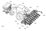
- the order combination 101 has a fertilizer container 102 in the front attachment to the front linkage 104 of the tractor 105. Furthermore, the harrow 103 has a central support frame 106 which is arranged via coupling elements to the three-point linkage of the tractor 105.
- the side frames 107 of the soil cultivator 103 divided into two subareas 103 'and 103 are pivotably arranged on this central supporting frame 106.
- a partial region 108' and 108" of the trailing roller 108 is arranged on each subarea 103 'and 103 "of the cultivator 103.
- the trailing roller 108 has the spaced to each other arranged roller elements 109 with the associated shares 110 and 111.
- the follower roller 108 has the spaced-apart tire-like roller elements 109 and 109 ', which are fastened by holding arms on the crossbar of the follower roller 108.
- roller elements of the follower roller 108 are arranged at a distance from one another and have a gap relative to one another.
- the roller elements 109 and 109 'solidify the soil in strips, so that the soil is reconsolidated in some areas.
- the order combination further has a distributor.
- This distributor is equipped in the embodiment as a precision seed drill with the singulator and seed hopper and a fertilizer distribution machine with fertilizer reservoir 102 and associated metering.
- the coulters and the fertilizer coulters of the coulter units are located in the areas not solidified by the roller elements 5.
- the crossbar on which both the roller elements as well as the coulters are arranged by means of their joint struts and, is located in front of the roller elements.
- the fertilizer coulters are at least partially in the intermediate region between the roller elements. Furthermore, the articulated struts that support the coulters extend through the intermediate region between the roller elements.
- the coulters are each assigned depth guide wheels. These depth guide wheels extend transversely to the direction of travel at least approximately over the gap between the adjacent roller elements, so that they re-consolidate the intermediate area between the roller elements and take over the task of rolling elements of the follower roller, so that the entire work area of the roller elements in conjunction with the Tiefen arrangementsmannn is reconsolidated.
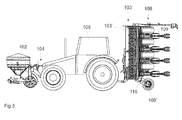
- the order combination 101 which in Fig. 1 is shown in the working position is in the in the Fig. 2 to 4 to pivot shown transport position.
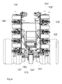
- the order combination 101 between the respective side frames 107 associated follower rollers 108 'and 108 "on a narrow center roller element 109', in particular the Fig. 4 can be seen.
- This narrow center roller element 109 ' is fastened to the support frame 106 via a separate holder 110. While the other roller elements 109 of the follower roller 108 are attached to the side frame 107.
- the center roller element 109 ' is formed in the transport position of the order combination 101 as a transport support wheel, in particular the Fig. 3 and 4 demonstrate.
- the center roller element 109 ' is arranged with a not shown in detail, an upright pivot axis having holding device 110 on the support frame 106 and about this axis, at least in the folded position of the side frame 107 according to the Fig. 2 to 8 freely swiveling.
- This center roller element 109 ' which serves as a transport support wheel, additionally supports the order combination 101 relative to the ground, so that the entire weight of the order combination 101 in the excavated position does not have to be borne by the tractor 105 or by the three-point coupling.
- the center roller element 109 ' With the above-described shuttle equipment is arranged on the middle frame 106.
- the center roller element 109 ' is arranged adjustable by means of not shown motor adjusting devices in the height direction relative to the support frame 106, so that the transport support wheel 109' can be brought into the appropriate position in the transport position and in the working position.
- the pendulum wheel suspension is associated with a locking device, by means of which the center roller element 109 'in the working position relative to the side frame 107 and support frame 106 can be locked.
Landscapes
- Life Sciences & Earth Sciences (AREA)
- Engineering & Computer Science (AREA)
- Mechanical Engineering (AREA)
- Soil Sciences (AREA)
- Environmental Sciences (AREA)
- Agricultural Machines (AREA)
- Soil Working Implements (AREA)
Abstract
Description
- Die Erfindung betrifft eine Bestellkombination gemäß des Oberbegriffes des Patentanspruches 1.
- Derartige Bestellkombinationen sind beispielsweise durch die
DE 102 24 861 A1 . Diese Bestellkombination ist an dem Dreipunktkraftheber eines Ackerschleppers angeordnet. Die Bestellkombination weist eine große Arbeitsbreite auf und besteht aus zwei an einem Zentralrahmen angeordneten Seiteneinheit die mit aus einer Arbeitsstellung in eine Transportstellung eingeklappt werden können. Damit auch Ackerschlepper mit geringer Hubkraft schwere Bestellkombinationen ausheben können und mit diesen sicher fahren können, ist bei dieser Bestellkombination vorgesehen, dass ein zusätzliches Stützrad mit einem weit nach hinten über die Bestellkombination hinausragende Tragarm angeordnet ist. Diese Ausgestaltung mit einem zusätzlichen Stützrad an einem separaten und langen Tragarm ist sehr aufwendig. - Der Erfindung liegt die Aufgabe zugrunde, die Anordnung und Ausgestaltung eines Transportstützelementes wesentlich zu vereinfachen.
- Diese Aufgabe wird erfindungemäß dadurch gelöst, dass in der Mitte der Bestellkombination zwischen den den jeweiligen Seitenrahmen zugeordneten Nachlaufwalzen ein schmales Mittelwalzenelement an dem Tragrahmen angeordnet ist.
- Somit können Schlepper mit geringer Hubkraft zum Ziehen der Bestellkombination eingesetzt werden. Hierdurch können ohne spezielle Laufräder eines Fahrwerkes trotzdem die Vorteile eines Fahrwerkes genutzt werden, in dem einige der Walzenelemente die Fahrwerkselemente bilden. Auch dieses trägt zu einer kompakten Bauweise der Bestellkombination bei.
- Bei Bestellkombinationen, deren Seitenrahmen einklappbar sind, ist vorgesehen, dass in der Mitte der Bestellkombination zwischen den den jeweiligen Seitenrahmen zugeordneten Nachlaufwalzen ein schmales Mittelwalzenelement an dem Tragrahmen angeordnet ist. Hierdurch ergibt sich eine vorteilhafte Ausgestaltung der Nachlaufwalze mit der Möglichkeit, das schmale Mittelwalzenelement als Fahrwerkselement zu nutzen, somit ist also das Mittelwalzenelement als Transportstützrad ausgestaltet.
- Um ein gutes Fahrverhalten der Bestellkombination mit dem als Transportstützrad wirkenden Mittelwalzenelement in der Transportfahrt zu erreichen, ist vorgesehen, dass das Mittelwalzenelement mit einer eine aufrechten Schwenkachse aufweisenden Haltevorrichtung an dem Tragrahmen angeordnet und um diese Achse zumindest in eingeklappter Position der Seitenrahmen frei schwenkbar ist. Hierdurch wird das Mittelwalzenelement schwenkbar aufgehängt und kann Lenkbewegungen des Schleppers folgen. In vorteilhafter Weise ist zur beweglichen Aufhängung des Mittelwalzenelementes vorgesehen, dass das Mittelwalzenelement mittels einer Pendelradaufhängung an dem Seitenrahmen angeordnet ist.
- Um über das Mittelwalzenelement die Bestellkombination zumindest unterstützend ausbilden zu können, ist vorgesehen, dass das Mittelwalzenelement mittels einer motorischen Stellvorrichtung in Höhenrichtung gegenüber dem Tragrahmen verstellbar angeordnet ist.
- Um während der Bestellarbeit eine gute Verdichtungsarbeit des Mittelwalzenelementes, welches als Transportstützrad dient und mittels einer Pendelradaufhängung aufgehängt ist, zu gewährleisten, ist vorgesehen, dass der Pendelradaufhängung eine Verriegelungseinrichtung zugeordnet ist, mittels welcher das Mittelwalzenelement in Arbeitsstellung der Seitenrahmen verriegelbar ist.
- Weitere Einzelheiten der Erfindung sind der Beispielsbeschreibung und den Zeichnungen zu entnehmen.
- Hierbei zeigen
- Fig. 1
- eine Bestellkombination mit größerer Arbeitsbreite mit zwei einklappbaren Seitenteilen und Düngerfronttank in Arbeitsstellung und perspektivischer Darstellung,
- Fig. 2
- die Bestellkombination gemäß
Fig. 1 in Transportstellung, in perspektivischer Darstellung, - Fig. 3
- die Bestellkombination gemäß
Fig. 2 in Seitenansicht und - Fig. 4
- die Bestellkombination gemäß den
Fig. 2 und3 in der Ansicht von hinten. - Die Bestellkombination 101 weist einen Düngerbehälter 102 im Frontanbau an den Frontkraftheber 104 des Ackerschleppers 105 auf. Weiterhin weist das Bodenbearbeitungsgerät 103 einen zentralen Tragrahmen 106 auf, der über Kupplungselemente an den Dreipunktkraftheber des Ackerschleppers 105 angeordnet ist. An diesem zentralen Tragrahmen 106 sind die Seitenrahmen 107 des in zwei Teilbereichen 103' und 103" unterteilten Bodenbearbeitungsgerätes 103 schwenkbar angeordnet. An jedem Teilbereich 103' und 103" des Bodenbearbeitungsgerätes 103 ist ein Teilbereich 108' und 108" der Nachlaufwalze 108 angeordnet. Die Nachlaufwalze 108 weist die beabstandet zueinander angeordneten Walzenelementen 109 mit den zugeordneten Scharen 110 und 111 auf.
- Die Nachlaufwalze 108 weist die beabstandet zueinander angeordneten reifenartigen Walzenelemente 109 und 109' auf, welche über Haltearme an dem Querbalken der Nachlaufwalze 108 befestigt sind.
- Wie bereits erwähnt, sind die Walzenelemente der Nachlaufwalze 108 beabstandet zueinander angeordnet und weisen einen Zwischenraum zueinander auf. Die Walzenelemente 109 und 109' verfestigen den Boden streifenweise, so dass der Boden in Teilbereichen rückverfestigt wird.
- Die Bestellkombination weist weiter eine Verteilmaschine auf. Diese Verteilmaschine ist im Ausführungsbeispiel als Einzelkornsämaschine mit dem Vereinzelungsorgan und Saatgutbehälter sowie einer Düngerverteilmaschine mit Düngervorratsbehälter 102 und zugeordneten Dosierorganen ausgestattet.
- In dem Zwischenraum zwischen den Walzenelementen bzw. in Fahrtrichtung gesehen mit diesem Zwischenräume fluchtend sind die einzelnen Scharelemente und der Verteilmaschine angeordnet.
- Die Säschare und die Düngerschare der Schareinheiten befinden sich in den nicht von den Walzenelementen 5 verfestigten Bereichen.
- Der Querbalken, an dem sowohl die Walzenelemente wie auch die Säschare mittels ihrer Gelenkstreben und angeordnet sind, befindet sich vor den Walzenelementen.
- Die Düngerschare befinden sich zumindest teilweise in dem Zwischenbereich zwischen den Walzenelementen. Weiterhin erstrecken sich die Gelenkstreben, die die Schare tragen, durch den Zwischenbereich zwischen den Walzenelementen. Den Säscharen sind jeweils Tiefenführungsräder zugeordnet. Diese Tiefenführungsräder erstrecken sich quer zur Fahrtrichtung gesehen zumindest annähernd über den Zwischenraum zwischen den einander benachbarten Walzenelementen, so dass sie den Zwischenbereich zwischen den Walzenelementen rückverfestigen und hier die Aufgabe der Walzenelemente der Nachlaufwalze übernehmen, so dass der gesamte Arbeitsbereich von den Walzenelementen in Verbindung mit den Tiefenführungsrädern rückverfestigt wird.
- Die Bestellkombination 101, die in
Fig. 1 in Arbeitsstellung dargestellt ist, ist in die in dieFig. 2 bis 4 dargestellte Transportstellung zu verschwenken. Hierbei weist die Bestellkombination 101 zwischen den den jeweiligen Seitenrahmen 107 zugeordneten Nachlaufwalzen 108' und 108" ein schmales Mittelwalzenelement 109' auf, wie insbesondere derFig. 4 zu entnehmen ist. Dieses schmale Mittelwalzenelement 109' ist über eine separate Halterung 110 an dem Tragrahmen 106 befestigt. Während die anderen Walzenelemente 109 der Nachlaufwalze 108 an den Seitenrahmen 107 befestigt sind. - Das Mittelwalzenelement 109' ist in der Transportstellung der Bestellkombination 101 als Transportstützrad ausgebildet, wie insbesondere die
Fig. 3 und4 zeigen. Das Mittelwalzenelement 109' ist mit einer nicht im einzelnen dargestellten, eine aufrechte Schwenkachse aufweisenden Haltevorrichtung 110 an dem Tragrahmen 106 angeordnet und um diese Achse zumindest in eingeklappter Position der Seitenrahmen 107 gemäß denFig. 2 bis 8 frei schwenkbar. Dieses Mittelwalzenelement 109', welches als Transportstützrad dient, stützt zusätzlich die Bestellkombination 101 gegenüber dem Boden ab, so dass das gesamte Gewicht der Bestellkombination 101 in ausgehobener Position nicht von dem Schlepper 105 bzw. von der Dreipunktkupplung getragen werden muss. - In nicht dargestellter Weise ist das Mittelwalzenelement109' mit der vorbeschriebenen Pendelausrüstung an dem Mittelrahmen 106 angeordnet. Das Mittelwalzenelement 109' ist mittels nicht dargestellter motorischer Stellvorrichtungen in Höhenrichtung gegenüber dem Tragrahmen 106 verstellbar angeordnet, so dass das Transportstützrad 109' in die entsprechende Position in der Transportstellung und in die Arbeitsstellung gebracht werden kann.
- In nicht dargestellter Weise ist der Pendelradaufhängung eine Verriegelungseinrichtung zugeordnet, mittels welcher das Mittelwalzenelement 109' in Arbeitsstellung gegenüber dem Seitenrahmen 107 und Tragrahmen 106 verriegelbar ist.
Claims (7)
- Bestellkombination bestehend aus einem Bodenbearbeitungsgerät mit an einem Tragrahmen angeordneten Anlenkpunkten für den Anbau an einen Traktordreipunktgestänge, wobei an dem Tragrahmen Seitenrahmen, an mit Bodenbearbeitungswerkzeugen und zugeordneten Nachlaufwalzen angeordnet sind, wobei das Bodenbearbeitungsgerät aus mehreren Geräteeinheiten besteht, die zusammen mit den Nachlaufwalzen um horizontale Achsen schwenkbar und einklappbar am Tragrahmen ausgebildet sind, wobei das Gerät aus vorzugsweise zwei unmittelbar nebeneinander angeordneten Bodenbearbeitungswerkzeugen tragenden Seitenrahmen besteht, die jeweils zusammen mit den Nachlaufwalzen in eine Transportstellung einschwenkbar angeordnet sind, dadurch gekennzeichnet, dass in der Mitte der Bestellkombination ( 101 ) zwischen den den jeweiligen Seitenrahmen ( 107 ) zugeordneten Nachlaufwalzen ( 108', 108") ein schmales Mittelwalzenelement ( 109') an dem Tragrahmen ( 106 ) angeordnet ist.
- Bestellkombination nach Anspruch 1, dadurch gekennzeichnet, dass das Mittelwalzenelement ( 109' ) als Transportstützrad ausgebildet ist.
- Bestellkombination nach einem oder mehreren der vorstehenden Ansprüche, dadurch gekennzeichnet, dass das Mittelwalzenelement ( 109' ) mit einer eine aufrechten Schwenkachse aufweisenden Haltevorrichtung ( 110 ) an dem Tragrahmen ( 106 ) angeordnet und um diese Achse zumindest in eingeklappter Position der Seitenrahmen ( 107 ) frei schwenkbar ist.
- Bestellkombination nach Anspruch 1, dadurch gekennzeichnet, dass das Mittelwalzenelement ( 109' ) mittels einer Pendelradaufhängung an dem Tragrahmen ( 106 ) angeordnet ist.
- Bestellkombination nach einem oder mehreren der vorstehenden Ansprüche, dadurch gekennzeichnet, dass das Mittelwalzenelement ( 109' ) mittels einer motorischen Stellvorrichtung in Höhenrichtung gegenüber dem Tragrahmen ( 106 ) verstellbar angeordnet ist.
- Bestellkombination nach einem oder mehreren der vorstehenden Ansprüche, dadurch gekennzeichnet, dass der Pendelradaufhängung eine Verriegelungseinrichtung zugeordnet ist, mittels welcher das Mittelwalzenelement in Arbeitsstellung der Seitenrahmen verriegelbar ist.
- Bestellkombination nach Anspruch 1, wobei der Bestellkombination eine Sämaschine mit zumindest einem Vorratsbehälter, der oberhalb des Tragrahmens oder der Nachlaufwalzen angeordnet ist, zugeordnet ist, dadurch gekennzeichnet, dass in der eingeklappten Position der Seitenrahmen die Seitenrahmen den Vorratsbehälter dicht umschließen bzw. einfassen der zusammen mit der für den Anbau oder Aufbau vorgesehenen Sämaschine auf dem Tragrahmen angeordnet ist.
Applications Claiming Priority (2)
| Application Number | Priority Date | Filing Date | Title |
|---|---|---|---|
| DE102009043814 | 2009-08-20 | ||
| DE102009044329A DE102009044329A1 (de) | 2009-08-20 | 2009-10-27 | Bestellkombination |
Publications (2)
| Publication Number | Publication Date |
|---|---|
| EP2289295A1 true EP2289295A1 (de) | 2011-03-02 |
| EP2289295B1 EP2289295B1 (de) | 2016-10-19 |
Family
ID=43495530
Family Applications (1)
| Application Number | Title | Priority Date | Filing Date |
|---|---|---|---|
| EP10401136.6A Not-in-force EP2289295B1 (de) | 2009-08-20 | 2010-08-12 | Bestellkombination |
Country Status (2)
| Country | Link |
|---|---|
| EP (1) | EP2289295B1 (de) |
| DE (1) | DE102009044329A1 (de) |
Cited By (3)
| Publication number | Priority date | Publication date | Assignee | Title |
|---|---|---|---|---|
| ITUB20153943A1 (it) * | 2015-09-28 | 2017-03-28 | Demaseminatrici S R L | Seminatrice ad ingombro variabile |
| EP3443831A1 (de) * | 2017-08-07 | 2019-02-20 | Horsch Maschinen GmbH | Landwirtschaftliche reiheneinheit zum verteilen von körnern |
| EP4124221A1 (de) | 2021-07-28 | 2023-02-01 | Kverneland Group Soest GmbH | Landwirtschaftliche maschine und landwirtschaftliche maschinenkombination |
Citations (5)
| Publication number | Priority date | Publication date | Assignee | Title |
|---|---|---|---|---|
| DE9214242U1 (de) * | 1992-10-21 | 1993-02-25 | Väderstadverken AB, Väderstad | Landwirtschaftsgerät |
| DE10224861A1 (de) | 2002-06-05 | 2003-12-24 | Amazonen Werke Dreyer H | Landwirtschaftliches Gerät |
| WO2004073381A2 (de) | 2003-02-20 | 2004-09-02 | Amazonen-Werke H.Dreyer Gmbh & Co.Kg | Landwirtschaftliches arbeitsgerät |
| WO2005115124A1 (de) * | 2004-05-29 | 2005-12-08 | Amazonen-Werke H. Dreyer Gnbh & Co. Kg | Fahrwerk für landwirtschaftliche bodenbearbeitungsmaschine |
| EP2055164A1 (de) * | 2007-11-02 | 2009-05-06 | Lemken GmbH & Co. KG | Einklappbare landwirtschaftliche Gerätekombination |
-
2009
- 2009-10-27 DE DE102009044329A patent/DE102009044329A1/de not_active Withdrawn
-
2010
- 2010-08-12 EP EP10401136.6A patent/EP2289295B1/de not_active Not-in-force
Patent Citations (5)
| Publication number | Priority date | Publication date | Assignee | Title |
|---|---|---|---|---|
| DE9214242U1 (de) * | 1992-10-21 | 1993-02-25 | Väderstadverken AB, Väderstad | Landwirtschaftsgerät |
| DE10224861A1 (de) | 2002-06-05 | 2003-12-24 | Amazonen Werke Dreyer H | Landwirtschaftliches Gerät |
| WO2004073381A2 (de) | 2003-02-20 | 2004-09-02 | Amazonen-Werke H.Dreyer Gmbh & Co.Kg | Landwirtschaftliches arbeitsgerät |
| WO2005115124A1 (de) * | 2004-05-29 | 2005-12-08 | Amazonen-Werke H. Dreyer Gnbh & Co. Kg | Fahrwerk für landwirtschaftliche bodenbearbeitungsmaschine |
| EP2055164A1 (de) * | 2007-11-02 | 2009-05-06 | Lemken GmbH & Co. KG | Einklappbare landwirtschaftliche Gerätekombination |
Cited By (4)
| Publication number | Priority date | Publication date | Assignee | Title |
|---|---|---|---|---|
| ITUB20153943A1 (it) * | 2015-09-28 | 2017-03-28 | Demaseminatrici S R L | Seminatrice ad ingombro variabile |
| EP3443831A1 (de) * | 2017-08-07 | 2019-02-20 | Horsch Maschinen GmbH | Landwirtschaftliche reiheneinheit zum verteilen von körnern |
| EP4124221A1 (de) | 2021-07-28 | 2023-02-01 | Kverneland Group Soest GmbH | Landwirtschaftliche maschine und landwirtschaftliche maschinenkombination |
| WO2023006233A1 (de) | 2021-07-28 | 2023-02-02 | Kverneland Group Soest Gmbh | Landwirtschaftliche maschine und landwirtschaftliche maschinenkombination |
Also Published As
| Publication number | Publication date |
|---|---|
| EP2289295B1 (de) | 2016-10-19 |
| DE102009044329A1 (de) | 2011-02-24 |
Similar Documents
| Publication | Publication Date | Title |
|---|---|---|
| EP0114983B1 (de) | Landwirtschaftlich nutzbares Arbeitsgerät | |
| DE102014104417B3 (de) | Bodenbearbeitungsgerät mit Striegel- oder Einebnungsvorrichtung | |
| EP2589283B1 (de) | Kombiniertes Bodenbearbeitungsgerät für große Arbeitsbreiten mit einklappbaren Seitenteilen | |
| EP1731012B1 (de) | Landmaschine mit nach vorn klappbaren Werkzeugen | |
| DE2534596C2 (de) | ||
| EP3381253B1 (de) | Landwirtschaftliche maschine mit tiefenführungselementen | |
| DE2557753C2 (de) | Schlepperbetriebene Maschinenkombination | |
| EP2289295B1 (de) | Bestellkombination | |
| DE2622649C2 (de) | Schlepperbetriebene Bodenbearbeitungsmaschine | |
| DE68913786T2 (de) | Bodenbearbeitungsmaschine. | |
| EP2868181B1 (de) | Landwirtschaftliche Verteilmaschine | |
| DE102006019032B4 (de) | Einklappbare landwirtschaftliche Bestellkombination | |
| DE102010013470B4 (de) | Vorrichtung zum Verteilen von Saatgut und/oder Dünger | |
| DE2735366A1 (de) | Anhaengevorrichtung fuer landmaschinen | |
| EP2286647B1 (de) | Bestellkombination | |
| DE3401228C2 (de) | ||
| DE3412962A1 (de) | Traggestell fuer ein landwirtschaftliches geraet | |
| DE2559341A1 (de) | Maschine zum ausbringen von duenger und saatgut | |
| WO2008080472A1 (de) | Gezogenes landwirtschaftliches arbeitsgerät | |
| DE19821394A1 (de) | Gezogene landwirtschaftliche Bestellkombination | |
| DE19833674A1 (de) | Aufgesattelte Kreiselegge | |
| DE2227586C3 (de) | Bodenbearbeitungsgerät mit mehreren Gerätetelien | |
| DE102022106208A1 (de) | Landwirtschaftliche Maschine mit Stützeinrichtung | |
| DE102006047890A1 (de) | Bodenbearbeitungsgerät mit großer Arbeitsbreite | |
| WO2013124217A1 (de) | Saemaschine |
Legal Events
| Date | Code | Title | Description |
|---|---|---|---|
| PUAI | Public reference made under article 153(3) epc to a published international application that has entered the european phase |
Free format text: ORIGINAL CODE: 0009012 |
|
| AK | Designated contracting states |
Kind code of ref document: A1 Designated state(s): AL AT BE BG CH CY CZ DE DK EE ES FI FR GB GR HR HU IE IS IT LI LT LU LV MC MK MT NL NO PL PT RO SE SI SK SM TR |
|
| AX | Request for extension of the european patent |
Extension state: BA ME RS |
|
| 17P | Request for examination filed |
Effective date: 20110527 |
|
| GRAP | Despatch of communication of intention to grant a patent |
Free format text: ORIGINAL CODE: EPIDOSNIGR1 |
|
| INTG | Intention to grant announced |
Effective date: 20160802 |
|
| GRAS | Grant fee paid |
Free format text: ORIGINAL CODE: EPIDOSNIGR3 |
|
| GRAA | (expected) grant |
Free format text: ORIGINAL CODE: 0009210 |
|
| AK | Designated contracting states |
Kind code of ref document: B1 Designated state(s): AL AT BE BG CH CY CZ DE DK EE ES FI FR GB GR HR HU IE IS IT LI LT LU LV MC MK MT NL NO PL PT RO SE SI SK SM TR |
|
| REG | Reference to a national code |
Ref country code: GB Ref legal event code: FG4D Free format text: NOT ENGLISH |
|
| REG | Reference to a national code |
Ref country code: CH Ref legal event code: EP |
|
| REG | Reference to a national code |
Ref country code: AT Ref legal event code: REF Ref document number: 837497 Country of ref document: AT Kind code of ref document: T Effective date: 20161115 |
|
| REG | Reference to a national code |
Ref country code: IE Ref legal event code: FG4D Free format text: LANGUAGE OF EP DOCUMENT: GERMAN |
|
| REG | Reference to a national code |
Ref country code: DE Ref legal event code: R096 Ref document number: 502010012595 Country of ref document: DE |
|
| REG | Reference to a national code |
Ref country code: SE Ref legal event code: TRGR |
|
| REG | Reference to a national code |
Ref country code: NL Ref legal event code: MP Effective date: 20161019 |
|
| REG | Reference to a national code |
Ref country code: LT Ref legal event code: MG4D |
|
| PG25 | Lapsed in a contracting state [announced via postgrant information from national office to epo] |
Ref country code: LV Free format text: LAPSE BECAUSE OF FAILURE TO SUBMIT A TRANSLATION OF THE DESCRIPTION OR TO PAY THE FEE WITHIN THE PRESCRIBED TIME-LIMIT Effective date: 20161019 |
|
| PG25 | Lapsed in a contracting state [announced via postgrant information from national office to epo] |
Ref country code: NO Free format text: LAPSE BECAUSE OF FAILURE TO SUBMIT A TRANSLATION OF THE DESCRIPTION OR TO PAY THE FEE WITHIN THE PRESCRIBED TIME-LIMIT Effective date: 20170119 Ref country code: GR Free format text: LAPSE BECAUSE OF FAILURE TO SUBMIT A TRANSLATION OF THE DESCRIPTION OR TO PAY THE FEE WITHIN THE PRESCRIBED TIME-LIMIT Effective date: 20170120 Ref country code: LT Free format text: LAPSE BECAUSE OF FAILURE TO SUBMIT A TRANSLATION OF THE DESCRIPTION OR TO PAY THE FEE WITHIN THE PRESCRIBED TIME-LIMIT Effective date: 20161019 |
|
| PG25 | Lapsed in a contracting state [announced via postgrant information from national office to epo] |
Ref country code: ES Free format text: LAPSE BECAUSE OF FAILURE TO SUBMIT A TRANSLATION OF THE DESCRIPTION OR TO PAY THE FEE WITHIN THE PRESCRIBED TIME-LIMIT Effective date: 20161019 Ref country code: HR Free format text: LAPSE BECAUSE OF FAILURE TO SUBMIT A TRANSLATION OF THE DESCRIPTION OR TO PAY THE FEE WITHIN THE PRESCRIBED TIME-LIMIT Effective date: 20161019 Ref country code: IS Free format text: LAPSE BECAUSE OF FAILURE TO SUBMIT A TRANSLATION OF THE DESCRIPTION OR TO PAY THE FEE WITHIN THE PRESCRIBED TIME-LIMIT Effective date: 20170219 Ref country code: FI Free format text: LAPSE BECAUSE OF FAILURE TO SUBMIT A TRANSLATION OF THE DESCRIPTION OR TO PAY THE FEE WITHIN THE PRESCRIBED TIME-LIMIT Effective date: 20161019 Ref country code: PT Free format text: LAPSE BECAUSE OF FAILURE TO SUBMIT A TRANSLATION OF THE DESCRIPTION OR TO PAY THE FEE WITHIN THE PRESCRIBED TIME-LIMIT Effective date: 20170220 Ref country code: NL Free format text: LAPSE BECAUSE OF FAILURE TO SUBMIT A TRANSLATION OF THE DESCRIPTION OR TO PAY THE FEE WITHIN THE PRESCRIBED TIME-LIMIT Effective date: 20161019 Ref country code: PL Free format text: LAPSE BECAUSE OF FAILURE TO SUBMIT A TRANSLATION OF THE DESCRIPTION OR TO PAY THE FEE WITHIN THE PRESCRIBED TIME-LIMIT Effective date: 20161019 |
|
| REG | Reference to a national code |
Ref country code: FR Ref legal event code: PLFP Year of fee payment: 8 |
|
| REG | Reference to a national code |
Ref country code: DE Ref legal event code: R097 Ref document number: 502010012595 Country of ref document: DE |
|
| PG25 | Lapsed in a contracting state [announced via postgrant information from national office to epo] |
Ref country code: DK Free format text: LAPSE BECAUSE OF FAILURE TO SUBMIT A TRANSLATION OF THE DESCRIPTION OR TO PAY THE FEE WITHIN THE PRESCRIBED TIME-LIMIT Effective date: 20161019 Ref country code: CZ Free format text: LAPSE BECAUSE OF FAILURE TO SUBMIT A TRANSLATION OF THE DESCRIPTION OR TO PAY THE FEE WITHIN THE PRESCRIBED TIME-LIMIT Effective date: 20161019 Ref country code: EE Free format text: LAPSE BECAUSE OF FAILURE TO SUBMIT A TRANSLATION OF THE DESCRIPTION OR TO PAY THE FEE WITHIN THE PRESCRIBED TIME-LIMIT Effective date: 20161019 Ref country code: SK Free format text: LAPSE BECAUSE OF FAILURE TO SUBMIT A TRANSLATION OF THE DESCRIPTION OR TO PAY THE FEE WITHIN THE PRESCRIBED TIME-LIMIT Effective date: 20161019 Ref country code: RO Free format text: LAPSE BECAUSE OF FAILURE TO SUBMIT A TRANSLATION OF THE DESCRIPTION OR TO PAY THE FEE WITHIN THE PRESCRIBED TIME-LIMIT Effective date: 20161019 |
|
| PLBE | No opposition filed within time limit |
Free format text: ORIGINAL CODE: 0009261 |
|
| STAA | Information on the status of an ep patent application or granted ep patent |
Free format text: STATUS: NO OPPOSITION FILED WITHIN TIME LIMIT |
|
| PG25 | Lapsed in a contracting state [announced via postgrant information from national office to epo] |
Ref country code: BG Free format text: LAPSE BECAUSE OF FAILURE TO SUBMIT A TRANSLATION OF THE DESCRIPTION OR TO PAY THE FEE WITHIN THE PRESCRIBED TIME-LIMIT Effective date: 20170119 Ref country code: SM Free format text: LAPSE BECAUSE OF FAILURE TO SUBMIT A TRANSLATION OF THE DESCRIPTION OR TO PAY THE FEE WITHIN THE PRESCRIBED TIME-LIMIT Effective date: 20161019 |
|
| 26N | No opposition filed |
Effective date: 20170720 |
|
| PG25 | Lapsed in a contracting state [announced via postgrant information from national office to epo] |
Ref country code: SI Free format text: LAPSE BECAUSE OF FAILURE TO SUBMIT A TRANSLATION OF THE DESCRIPTION OR TO PAY THE FEE WITHIN THE PRESCRIBED TIME-LIMIT Effective date: 20161019 |
|
| REG | Reference to a national code |
Ref country code: CH Ref legal event code: PL |
|
| PG25 | Lapsed in a contracting state [announced via postgrant information from national office to epo] |
Ref country code: MC Free format text: LAPSE BECAUSE OF FAILURE TO SUBMIT A TRANSLATION OF THE DESCRIPTION OR TO PAY THE FEE WITHIN THE PRESCRIBED TIME-LIMIT Effective date: 20161019 |
|
| GBPC | Gb: european patent ceased through non-payment of renewal fee |
Effective date: 20170812 |
|
| PG25 | Lapsed in a contracting state [announced via postgrant information from national office to epo] |
Ref country code: LI Free format text: LAPSE BECAUSE OF NON-PAYMENT OF DUE FEES Effective date: 20170831 Ref country code: CH Free format text: LAPSE BECAUSE OF NON-PAYMENT OF DUE FEES Effective date: 20170831 |
|
| REG | Reference to a national code |
Ref country code: IE Ref legal event code: MM4A |
|
| REG | Reference to a national code |
Ref country code: BE Ref legal event code: MM Effective date: 20170831 |
|
| PG25 | Lapsed in a contracting state [announced via postgrant information from national office to epo] |
Ref country code: LU Free format text: LAPSE BECAUSE OF NON-PAYMENT OF DUE FEES Effective date: 20170812 |
|
| REG | Reference to a national code |
Ref country code: FR Ref legal event code: PLFP Year of fee payment: 9 |
|
| PG25 | Lapsed in a contracting state [announced via postgrant information from national office to epo] |
Ref country code: IE Free format text: LAPSE BECAUSE OF NON-PAYMENT OF DUE FEES Effective date: 20170812 Ref country code: GB Free format text: LAPSE BECAUSE OF NON-PAYMENT OF DUE FEES Effective date: 20170812 |
|
| PG25 | Lapsed in a contracting state [announced via postgrant information from national office to epo] |
Ref country code: BE Free format text: LAPSE BECAUSE OF NON-PAYMENT OF DUE FEES Effective date: 20170831 |
|
| PG25 | Lapsed in a contracting state [announced via postgrant information from national office to epo] |
Ref country code: MT Free format text: LAPSE BECAUSE OF FAILURE TO SUBMIT A TRANSLATION OF THE DESCRIPTION OR TO PAY THE FEE WITHIN THE PRESCRIBED TIME-LIMIT Effective date: 20161019 |
|
| PG25 | Lapsed in a contracting state [announced via postgrant information from national office to epo] |
Ref country code: HU Free format text: LAPSE BECAUSE OF FAILURE TO SUBMIT A TRANSLATION OF THE DESCRIPTION OR TO PAY THE FEE WITHIN THE PRESCRIBED TIME-LIMIT; INVALID AB INITIO Effective date: 20100812 |
|
| PG25 | Lapsed in a contracting state [announced via postgrant information from national office to epo] |
Ref country code: CY Free format text: LAPSE BECAUSE OF NON-PAYMENT OF DUE FEES Effective date: 20161019 |
|
| PG25 | Lapsed in a contracting state [announced via postgrant information from national office to epo] |
Ref country code: MK Free format text: LAPSE BECAUSE OF FAILURE TO SUBMIT A TRANSLATION OF THE DESCRIPTION OR TO PAY THE FEE WITHIN THE PRESCRIBED TIME-LIMIT Effective date: 20161019 |
|
| PG25 | Lapsed in a contracting state [announced via postgrant information from national office to epo] |
Ref country code: TR Free format text: LAPSE BECAUSE OF FAILURE TO SUBMIT A TRANSLATION OF THE DESCRIPTION OR TO PAY THE FEE WITHIN THE PRESCRIBED TIME-LIMIT Effective date: 20161019 |
|
| PG25 | Lapsed in a contracting state [announced via postgrant information from national office to epo] |
Ref country code: AL Free format text: LAPSE BECAUSE OF FAILURE TO SUBMIT A TRANSLATION OF THE DESCRIPTION OR TO PAY THE FEE WITHIN THE PRESCRIBED TIME-LIMIT Effective date: 20161019 |
|
| REG | Reference to a national code |
Ref country code: DE Ref legal event code: R081 Ref document number: 502010012595 Country of ref document: DE Owner name: AMAZONEN-WERKE H. DREYER SE & CO. KG, DE Free format text: FORMER OWNER: AMAZONEN-WERKE H. DREYER GMBH & CO. KG, 49205 HASBERGEN, DE |
|
| PGFP | Annual fee paid to national office [announced via postgrant information from national office to epo] |
Ref country code: IT Payment date: 20210712 Year of fee payment: 12 Ref country code: AT Payment date: 20210726 Year of fee payment: 12 Ref country code: FR Payment date: 20210714 Year of fee payment: 12 |
|
| PGFP | Annual fee paid to national office [announced via postgrant information from national office to epo] |
Ref country code: SE Payment date: 20210810 Year of fee payment: 12 Ref country code: DE Payment date: 20210630 Year of fee payment: 12 |
|
| REG | Reference to a national code |
Ref country code: DE Ref legal event code: R119 Ref document number: 502010012595 Country of ref document: DE |
|
| REG | Reference to a national code |
Ref country code: SE Ref legal event code: EUG |
|
| REG | Reference to a national code |
Ref country code: AT Ref legal event code: MM01 Ref document number: 837497 Country of ref document: AT Kind code of ref document: T Effective date: 20220812 |
|
| PG25 | Lapsed in a contracting state [announced via postgrant information from national office to epo] |
Ref country code: SE Free format text: LAPSE BECAUSE OF NON-PAYMENT OF DUE FEES Effective date: 20220813 Ref country code: AT Free format text: LAPSE BECAUSE OF NON-PAYMENT OF DUE FEES Effective date: 20220812 |
|
| PG25 | Lapsed in a contracting state [announced via postgrant information from national office to epo] |
Ref country code: IT Free format text: LAPSE BECAUSE OF NON-PAYMENT OF DUE FEES Effective date: 20220812 Ref country code: FR Free format text: LAPSE BECAUSE OF NON-PAYMENT OF DUE FEES Effective date: 20220831 Ref country code: DE Free format text: LAPSE BECAUSE OF NON-PAYMENT OF DUE FEES Effective date: 20230301 |