EP2288477B1 - Motorisiertes gelenk mit zwei drehverbindungen und das gelenk einsetzender humanoidroboter - Google Patents
Motorisiertes gelenk mit zwei drehverbindungen und das gelenk einsetzender humanoidroboter Download PDFInfo
- Publication number
- EP2288477B1 EP2288477B1 EP09730983A EP09730983A EP2288477B1 EP 2288477 B1 EP2288477 B1 EP 2288477B1 EP 09730983 A EP09730983 A EP 09730983A EP 09730983 A EP09730983 A EP 09730983A EP 2288477 B1 EP2288477 B1 EP 2288477B1
- Authority
- EP
- European Patent Office
- Prior art keywords
- motor
- axis
- joint
- pivot
- articulation
- Prior art date
- Legal status (The legal status is an assumption and is not a legal conclusion. Google has not performed a legal analysis and makes no representation as to the accuracy of the status listed.)
- Active
Links
- 230000002441 reversible effect Effects 0.000 claims description 2
- 239000003638 chemical reducing agent Substances 0.000 abstract description 13
- 210000000245 forearm Anatomy 0.000 description 22
- 238000010586 diagram Methods 0.000 description 5
- 238000004519 manufacturing process Methods 0.000 description 2
- 239000000463 material Substances 0.000 description 2
- 210000001364 upper extremity Anatomy 0.000 description 2
- 229920000049 Carbon (fiber) Polymers 0.000 description 1
- 239000004952 Polyamide Substances 0.000 description 1
- 239000004917 carbon fiber Substances 0.000 description 1
- 238000009429 electrical wiring Methods 0.000 description 1
- 210000003414 extremity Anatomy 0.000 description 1
- 230000012010 growth Effects 0.000 description 1
- 239000004033 plastic Substances 0.000 description 1
- 229920002647 polyamide Polymers 0.000 description 1
- -1 polytetrafluoroethylene Polymers 0.000 description 1
- 229920001343 polytetrafluoroethylene Polymers 0.000 description 1
- 239000004810 polytetrafluoroethylene Substances 0.000 description 1
- 108090000623 proteins and genes Proteins 0.000 description 1
Images


Classifications
-
- B—PERFORMING OPERATIONS; TRANSPORTING
- B25—HAND TOOLS; PORTABLE POWER-DRIVEN TOOLS; MANIPULATORS
- B25J—MANIPULATORS; CHAMBERS PROVIDED WITH MANIPULATION DEVICES
- B25J17/00—Joints
- B25J17/02—Wrist joints
- B25J17/0258—Two-dimensional joints
- B25J17/0275—Universal joints, e.g. Hooke, Cardan, ball joints
-
- Y—GENERAL TAGGING OF NEW TECHNOLOGICAL DEVELOPMENTS; GENERAL TAGGING OF CROSS-SECTIONAL TECHNOLOGIES SPANNING OVER SEVERAL SECTIONS OF THE IPC; TECHNICAL SUBJECTS COVERED BY FORMER USPC CROSS-REFERENCE ART COLLECTIONS [XRACs] AND DIGESTS
- Y10—TECHNICAL SUBJECTS COVERED BY FORMER USPC
- Y10S—TECHNICAL SUBJECTS COVERED BY FORMER USPC CROSS-REFERENCE ART COLLECTIONS [XRACs] AND DIGESTS
- Y10S901/00—Robots
- Y10S901/19—Drive system for arm
- Y10S901/25—Gearing
- Y10S901/26—Gearing including bevel gear
-
- Y—GENERAL TAGGING OF NEW TECHNOLOGICAL DEVELOPMENTS; GENERAL TAGGING OF CROSS-SECTIONAL TECHNOLOGIES SPANNING OVER SEVERAL SECTIONS OF THE IPC; TECHNICAL SUBJECTS COVERED BY FORMER USPC CROSS-REFERENCE ART COLLECTIONS [XRACs] AND DIGESTS
- Y10—TECHNICAL SUBJECTS COVERED BY FORMER USPC
- Y10T—TECHNICAL SUBJECTS COVERED BY FORMER US CLASSIFICATION
- Y10T74/00—Machine element or mechanism
- Y10T74/20—Control lever and linkage systems
- Y10T74/20207—Multiple controlling elements for single controlled element
- Y10T74/20305—Robotic arm
- Y10T74/20317—Robotic arm including electric motor
-
- Y—GENERAL TAGGING OF NEW TECHNOLOGICAL DEVELOPMENTS; GENERAL TAGGING OF CROSS-SECTIONAL TECHNOLOGIES SPANNING OVER SEVERAL SECTIONS OF THE IPC; TECHNICAL SUBJECTS COVERED BY FORMER USPC CROSS-REFERENCE ART COLLECTIONS [XRACs] AND DIGESTS
- Y10—TECHNICAL SUBJECTS COVERED BY FORMER USPC
- Y10T—TECHNICAL SUBJECTS COVERED BY FORMER US CLASSIFICATION
- Y10T74/00—Machine element or mechanism
- Y10T74/20—Control lever and linkage systems
- Y10T74/20207—Multiple controlling elements for single controlled element
- Y10T74/20305—Robotic arm
- Y10T74/20329—Joint between elements
- Y10T74/20335—Wrist
Definitions
- the invention relates to a motorized articulation with two pivot links and a humanoid robot implementing the articulation. More particularly, the invention relates to a hinge according to the preamble of claim 1. Such an articulation is known from the document EP-A-1207024 . The invention finds particular utility in the production of humanoid robots whose ergonomics are to be improved.
- Such robots are equipped with many joints to move different parts of the body of the robot such as the head or limbs.
- Certain joints of the human body such as the shoulder, the elbow or the neck can be reproduced in a robot by means of a joint comprising two pivot links also called double pivot connection. More specifically, the output of the first pivot connection forms the input of the second pivot link.
- the forearm is articulated relative to the arm so as to allow a first rotation of the forearm about an axis in which the forearm extends and a second rotation around an axis orthogonal to the first axis.
- the forearm has two degrees of freedom in rotation relative to the arm.
- the joints are motorized for example by means of rotary electric motors to control each a degree of freedom in rotation.
- the motors can be aligned with the respective axes of rotation as for example described in the documents EP-A-1 207 024 and US-A-5,967,580 .
- This arrangement is simple to implement but, in the case of the elbow, for example, one of the motors is necessarily prominent with respect to the joint. This excrescence gene some movements of the robot.
- the protuberances formed by the motors at the elbows must extend outwardly of the body.
- the growths are placed symmetrically with respect to a vertical axis forming the spinal column of the robot. This provision requires that the joints are also symmetrical. The joints can not be identical thus reducing the standardization of the mechanical parts constituting the robot.
- the invention aims to overcome all or part of these problems by removing the excrescence due to the engine.
- the invention makes it possible to improve the compactness of joints comprising two pivot links.
- the subject of the invention is a joint according to claim 1.
- the invention also relates to a humanoid robot comprising at least one hinge according to the invention.
- the invention is described in relation to a bend of a humanoid robot.
- the invention is not limited to this elbow and it is of course possible to implement it for any motorized double pivot joint articulation, especially for other joints of a humanoid robot such as the neck or shoulders.
- the figure 1 represents a portion of an upper limb 10 of a humanoid robot.
- the upper limb 10 comprises an arm 11 and a forearm 12.
- a hinge 13 allows the forearm 12 to move relative to the arm 11 along two axes of rotation.
- a first axis 14 extends in a main direction of the forearm 11 and a second axis 15 is orthogonal to the axis 14.
- the articulation 13 comprises two pivot links 16 and 17.
- the pivot connection 16 allows the rotation of the forearm 12 about the axis 14 and the pivot connection 17 allows the rotation of the forearm 12 about the axis 15.
- the pivot links 16 and 17 are partly hidden by a cowling of the arm 11 and the forearm 12.
- the configuration according to which the axes 14 and 15 are orthogonal is preferred. To implement the invention, it is of course possible to achieve a joint in which the axes 14 and 15 are not concurrent. In general, the invention may be implemented for non-parallel axes 14 and 15.
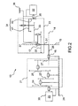
- the figure 2 represents a kinematic diagram of a articulation 13 comprising a first motor 20 driving the pivot connection 16 through a first speed reducer 21 and a second motor 22 driving the pivot connection 17 through a second speed reducer 23.
- the motors 20 and 22 are rotatable. They can be of any type and for example electric motors with direct current.
- the speed reducer 21 has parallel axes. It includes several gear trains. In the example shown, four gear trains 24 to 27 succeed each other to obtain the desired reduction ratio.
- the motor 20 drives the train 24 and an output shaft 28 of the gear train 27 forms a rotating part of the pivot connection 16.
- a fixed part of the pivot link 16 is formed by a bearing structure 29 of the arm 11.
- a stator 30 of the motor 20 is also integral with the supporting structure 29.
- the rotation of the motor 20 makes it possible to check, in the pivot connection 16, through the gearbox 21, the different parameters of the movement of the shaft 28 with respect to the supporting structure 29 namely, angular position, speed and torque.
- the motor 20 therefore controls the movement of the forearm 11 about the axis 14.
- the output shaft 28 of the gearbox 21 is also secured to a movable portion 31 forming an output shaft of the gearbox 23.
- the shaft 28 extends along the axis 14 and the movable portion 31 along the axis 15 In the configuration described, the movable portion 31 is therefore perpendicular to the shaft 28.
- the gearbox 23 comprises two gear trains 32 and 33 and a gear train 34 forming a gearbox to a shaft
- the angle of return 34 allows the motor 22 to be aligned with a carrier structure 36 of the forearm 12. More precisely, an output shaft 35 of the motor 22 extends in a longitudinal direction. the forearm 12.
- the angle gear 34 makes it possible to prevent the motor 22 from being aligned with the axis 15.
- the forearm 12 extends substantially perpendicular to the axis 15.
- the angle gear 34 provides a substantially straight angle between the axis 15 of the pivot connection 17 and the output shaft 35 of the mote 22.
- a fixed part 37 of the pivot connection 17 is integral with the supporting structure 36. The rotation of the motor 22 makes it possible to control, in the pivot connection 17, through the gear unit 23, the movement of the movable part 31 relative to at a fixed part 37 of the pivot connection 17 and therefore the movement of the forearm 11 about the axis 15.
- the figure 3 represents an exemplary embodiment of main parts of the schematic joint on the figure 2 . It contains the motor 20 driving the shaft 28 via the gearbox 21. To avoid overloading the figure 3 in the pivot connection 16, only the shaft 28 is shown, the hinge also comprises a bearing not shown and allowing the rotation and the guiding of the shaft 28 relative to the bearing structure 29.
- the shaft 28 is integral with a fork 40 in which the shaft 31, forming the movable portion of the pivot connection 17, is immobilized.
- the motor 22 and the gearbox 23 are also shown.
- the gearbox comprises four gear trains including the gearbox 34.
- An additional gearbox stage 33a is added with respect to the kinematic diagram of the gearbox. figure 2 .
- the number of gear trains is small in the implementation of the invention. It depends on the reduction ratio desired for the reducer in question.
- the angle gear 34 advantageously comprises a face gear 41 associated with a pinion 42, for example integral with the output shaft 35 of the motor 22.
- a gear 41 faces has several advantages over the use bevel gears to provide a bevel gear. These have a reduced reduction ratio, are sensitive to misalignment of their axes and have a higher manufacturing cost than the combination of a gear face with a spur gear.
- the combination of a face gear and a spur gear also eliminates the axial forces generated by bevel gears.
- the speed reducers 21 and 23 can have significant reduction ratios of the order of 150 to 200 to allow precise control of small movements of the forearm 12. It is advantageous that the gearboxes 21 and 23 are reversible in order to to be able to move the forearm 12 by means of an action external to the robot without damaging the gearboxes 21 and 23.
- the base material can also be loaded with carbon fibers to improve the mechanical characteristics of the reducers 21 and 23.
- the figure 4 represents a kinematic diagram of an embodiment of the invention.
- the hinge 13 comprises a first motor 50 driving the pivot connection 16 through a first speed reducer 51 and a second motor 52 driving the pivot connection 17 through a second speed reducer 53.
- the motors 50 and 52 are similar to the motors 20 and 22.
- the speed reducer 51 has parallel axes. It comprises, for example, three sets of spur gears 54 to 56 in succession.
- the motor 50 drives the train 54 and the gear train 56 drives a stator 60 of the motor 52.
- the stator 60 forms a rotating part of the pivot link 16.
- a fixed part of the pivot link 16 is formed by a bearing structure 29 of the arm 11.
- the stator 60 of the motor 52 is integral with the output axis 14 of the gear unit 51.
- An output shaft 61 of the motor 52 forms the input of the gearbox 53 comprising a bevel gear 62 followed by two gear trains 63 and 64.
- An output shaft 65 of the train 64 forms the movable part of the pivot link 17.
- the output shaft 65 is secured to the carrier structure 36 of the forearm 12.
- the angle gear 62 can provide a substantially straight angle between the axis 15 of the pivot connection 17, according to which turns the motor 52, and the output shaft 65 of the gearbox 53.
- the fixed portion of the pivot connection 17 is integral with the stator 60 of the motor 52.
- the axis of rotation of the motor 52 is parallel to the axis of rotation of the motor 50.
- none of the motors 50 and 51 nor the gear units 51 and 53 are located in the forearm 12. All the electrical controls of the motors 50 and 51 can be arranged in the arm 11. It is thus possible to limit the electrical wiring passing through the joint 13. This arrangement also reduces the inertia of the joint. Indeed, compared to the carrier structure 29 of the arm, the stator 60 of the motor 52 rotates only around the axis 14 of its output shaft 61.
- the figure 5 represents an exemplary embodiment of main parts of the schematic joint on the figure 4 . It contains the motor 50 driving the stator 60 of the motor 52 through the gear 51 rotating around the axis 14. The motor 52 drives the shaft 65 and the carrier structure via the gear 53 in rotation around the axis 15. As previously, the angle gear 62 may comprise a face gear 66 driven by a pinion gear 67 integral with the output shaft 61 of the motor 52.
- Gear units 21, 23, 51 and 53 each comprise a plurality of spur gear trains which can be replaced in each gear unit by an epicyclic gear train. This type of train is generally more compact than a series of gear trains for large gear ratios.
- the figure 6 represents a variant of the hinge 13 of the second embodiment, assembled in its environment.
- the motors 50 and 52 as well as the gearbox 51 are arranged inside the arm 11. Only the gearbox 53 appears between the cowling of the arm 11 and that of the arm 12.
- the gearbox comprises an epicyclic gear train 68 replacing the succession of gear trains 63 and 64.
- the articulation 13 connects two elements of the robot and the components of the articulation 13 are included in the volume of the elements and in a spherical volume 70 disposed between the two elements and whose diameter is smaller than transverse dimensions d11 and d12 of the two elements.
- the gearbox 53 can be inscribed in the spherical volume 70 situated between the arm 11 and the forearm 12, the diameter of the spherical volume 70 being smaller than transverse dimensions d11 and d12, respectively of the arm 11 and the forearm 12.
- This spherical volume 70 very small, avoids any prominence of the joint 13 may hinder the movements of the robot.
- Spherical volume 70 of reduced size also exists in the first embodiment.
- the epicyclic gear train 68 makes it possible to reduce the spherical volume 70.
Landscapes
- Engineering & Computer Science (AREA)
- Robotics (AREA)
- Mechanical Engineering (AREA)
- Manipulator (AREA)
Claims (6)
- Gelenk, das zwei Drehverbindungen (16, 17) umfasst, deren Achsen (14, 15) nicht parallel sind, wobei ein erster Motor (50) eine erste (16) der beiden Drehverbindungen durch einen ersten Drehzahlbegrenzer (51) mit parallelen Achsen antreibt und ein zweiter Motor (52) eine zweite (17) der beiden Drehverbindungen durch einen zweiten Drehzahlbegrenzer (53) antreibt, dadurch gekennzeichnet, dass die Drehachse des zweiten Motors (52) parallel zur Drehachse des ersten Motors (50) ist, und dadurch, dass der zweite Drehzahlbegrenzer (53) ein Kegelradgetriebe (62) zwischen dem Motor (52) und der Drehverbindung umfasst, die durch den Drehzahlbegrenzer (53) verbunden sind.
- Gelenk nach Anspruch 1, dadurch gekennzeichnet, dass das Kegelradgetriebe (62) ein Kronrad (67) umfasst.
- Gelenk nach einem der vorherigen Ansprüche, dadurch gekennzeichnet, dass einer der Drehzahlbegrenzer (51, 53) ein Planetenradgetriebe umfasst.
- Gelenk nach einem der vorherigen Ansprüche, dadurch gekennzeichnet, dass die Drehzahlbegrenzer (51, 53) reversibel sind.
- Humanoider Roboter, dadurch gekennzeichnet, dass er wenigstens ein Gelenk (13) nach einem der vorherigen Ansprüche umfasst.
- Humanoider Roboter nach Anspruch 5, dadurch gekennzeichnet, dass das Gelenk (13) zwei Elemente des Roboters verbindet, und dadurch, dass die Komponenten des Gelenks (13) im Volumen der Elemente und in einem sphärischen Volumen (70) enthalten sind, das zwischen den beiden Elementen angeordnet ist und dessen Durchmesser geringer ist als die Querabmessungen (d11 und d12) der beiden Elemente.
Applications Claiming Priority (2)
| Application Number | Priority Date | Filing Date | Title |
|---|---|---|---|
| FR0801953A FR2929875B1 (fr) | 2008-04-09 | 2008-04-09 | Articulation motorisee a deux liaisons pivots et robots humanoide mettant en oeuvre l'articulation |
| PCT/EP2009/054082 WO2009124904A1 (fr) | 2008-04-09 | 2009-04-06 | Articulation motorisee a deux liaisons pivots et robot humanoide mettant en oeuvre l'articulation |
Publications (2)
| Publication Number | Publication Date |
|---|---|
| EP2288477A1 EP2288477A1 (de) | 2011-03-02 |
| EP2288477B1 true EP2288477B1 (de) | 2011-10-05 |
Family
ID=39642951
Family Applications (1)
| Application Number | Title | Priority Date | Filing Date |
|---|---|---|---|
| EP09730983A Active EP2288477B1 (de) | 2008-04-09 | 2009-04-06 | Motorisiertes gelenk mit zwei drehverbindungen und das gelenk einsetzender humanoidroboter |
Country Status (7)
| Country | Link |
|---|---|
| US (1) | US8997599B2 (de) |
| EP (1) | EP2288477B1 (de) |
| JP (1) | JP5560495B2 (de) |
| CN (1) | CN102026782B (de) |
| AT (1) | ATE527088T1 (de) |
| FR (1) | FR2929875B1 (de) |
| WO (1) | WO2009124904A1 (de) |
Cited By (1)
| Publication number | Priority date | Publication date | Assignee | Title |
|---|---|---|---|---|
| DE102015017296B3 (de) | 2015-08-14 | 2021-10-07 | Franka Emika Gmbh | Robotersystem |
Families Citing this family (35)
| Publication number | Priority date | Publication date | Assignee | Title |
|---|---|---|---|---|
| FR2929875B1 (fr) * | 2008-04-09 | 2012-01-13 | Aldebaran Robotics | Articulation motorisee a deux liaisons pivots et robots humanoide mettant en oeuvre l'articulation |
| CN102069493A (zh) * | 2009-11-19 | 2011-05-25 | 鸿富锦精密工业(深圳)有限公司 | 机器人臂部件及机器人 |
| CN101927497B (zh) * | 2010-07-30 | 2012-02-01 | 华南理工大学 | 一种单自由度机器人摆转关节模块 |
| TW201406508A (zh) * | 2012-08-13 | 2014-02-16 | Mirle Automation Corp | 具有多軸轉動機構之機器人 |
| RU2564799C2 (ru) * | 2013-09-23 | 2015-10-10 | Научно-исследовательская лаборатория автоматизации проектирования, общество с ограниченной ответственностью (НИЛ АП, ООО) | Сустав руки робота |
| WO2015088655A1 (en) * | 2013-12-12 | 2015-06-18 | Covidien Lp | Gear train assemblies for robotic surgical systems |
| GB2540756B (en) * | 2015-07-22 | 2021-03-31 | Cmr Surgical Ltd | Gear packaging for robot arms |
| GB2541369B (en) * | 2015-07-22 | 2021-03-31 | Cmr Surgical Ltd | Drive mechanisms for robot arms |
| EP3524394B1 (de) | 2015-07-22 | 2024-02-21 | CMR Surgical Limited | Drehmomentsensoren |
| GB201512966D0 (en) * | 2015-07-22 | 2015-09-02 | Cambridge Medical Robotics Ltd | Drive arrangements for robot arms |
| DE102015012959B4 (de) | 2015-10-08 | 2019-01-17 | Franka Emika Gmbh | Robotersystem und Verfahren zur Steuerung eines Robotersystems |
| DE102015012961B4 (de) | 2015-10-08 | 2022-05-05 | Kastanienbaum GmbH | Robotersystem |
| DE102015012962A1 (de) | 2015-10-08 | 2017-04-13 | Sami Haddadin | Robotersystem |
| DE202016001164U1 (de) | 2016-02-22 | 2016-03-10 | Lakeview Innovation Ltd. | Robotergelenkantrieb mit Encoder |
| DE102016004787B4 (de) | 2016-04-20 | 2023-02-02 | Franka Emika Gmbh | Antriebsvorrichtung für einen Roboter und Verfahren zu ihrer Herstellung |
| DE102016004788A1 (de) | 2016-04-20 | 2017-10-26 | Kastanienbaum GmbH | Verfahren zur Herstellung eines Roboters und Vorrichtung zur Durchführung dieses Verfahrens |
| CN106003008A (zh) * | 2016-06-15 | 2016-10-12 | 上海未来伙伴机器人有限公司 | 类人机器人智能电机装置 |
| JP6940544B2 (ja) * | 2016-08-05 | 2021-09-29 | ファナック株式会社 | 回転軸モジュールおよび多関節ロボット |
| JP6499620B2 (ja) | 2016-08-05 | 2019-04-10 | ファナック株式会社 | 回転軸モジュールおよび多関節ロボット |
| JP6571703B2 (ja) * | 2017-02-13 | 2019-09-04 | ファナック株式会社 | 搬送用ツール |
| CN106863347B (zh) * | 2017-03-07 | 2023-08-18 | 壹利特机器人科技(常州)有限公司 | 一种模块化两自由度机器人关节 |
| CN107344365B (zh) * | 2017-07-03 | 2024-04-19 | 深圳市优必选科技有限公司 | 机器人关节驱动结构及机器人 |
| JP1607841S (de) * | 2017-07-12 | 2019-12-23 | ||
| JP1605286S (de) * | 2017-07-18 | 2019-11-25 | ||
| JP1605285S (de) * | 2017-07-18 | 2019-11-25 | ||
| JP1605288S (de) * | 2017-07-18 | 2019-11-25 | ||
| JP1605289S (de) * | 2017-07-18 | 2019-11-25 | ||
| JP1605287S (de) * | 2017-07-18 | 2019-11-25 | ||
| CN107825465A (zh) * | 2017-11-14 | 2018-03-23 | 徐州欧普莱斯工业机械有限公司 | 一种防护关节损伤的多关节机械臂 |
| JP1615136S (de) * | 2018-03-29 | 2020-03-30 | ||
| JP1615134S (de) * | 2018-03-29 | 2020-03-30 | ||
| JP1615133S (de) * | 2018-03-29 | 2020-03-30 | ||
| JP1615135S (de) * | 2018-03-29 | 2020-03-30 | ||
| JP1623231S (de) * | 2018-04-18 | 2020-07-13 | ||
| JP1623232S (de) * | 2018-04-18 | 2020-07-13 |
Family Cites Families (35)
| Publication number | Priority date | Publication date | Assignee | Title |
|---|---|---|---|---|
| FR2446951B1 (fr) * | 1979-01-17 | 1985-06-07 | Renault | Articulation a rotule pour bras polyarticule |
| JPS5851090A (ja) * | 1981-09-21 | 1983-03-25 | 株式会社東芝 | 関節装置 |
| US4512710A (en) * | 1982-09-03 | 1985-04-23 | Textron Inc. | Robot forearm |
| US4624621A (en) * | 1982-10-21 | 1986-11-25 | Kabushiki Kaisha Kobe Seiko Sho | Wrist mechanism for industrial robots and the like |
| US4579016A (en) * | 1983-03-01 | 1986-04-01 | Westinghouse Electric Corp. | Self-contained two-axis wrist module |
| JPS59174278A (ja) * | 1983-03-22 | 1984-10-02 | Yaskawa Electric Mfg Co Ltd | 産業用ロボツトの手首機構 |
| JPS60167796A (ja) * | 1984-02-03 | 1985-08-31 | 株式会社東芝 | 関接 |
| JP2602815B2 (ja) * | 1986-08-08 | 1997-04-23 | 株式会社東芝 | 関節装置 |
| US4828453A (en) * | 1987-04-21 | 1989-05-09 | The United States Of America As Represented By The United States Department Of Energy | Modular multimorphic kinematic arm structure and pitch and yaw joint for same |
| JPH0544072Y2 (de) * | 1987-07-03 | 1993-11-08 | ||
| FR2620837B1 (fr) * | 1987-09-21 | 1990-11-30 | Commissariat Energie Atomique | Dispositif d'orientation d'un objet autour de deux axes de rotation |
| US5046914A (en) * | 1988-07-12 | 1991-09-10 | Cybermation, Inc. | Parallel lifting device |
| DE3939836A1 (de) * | 1988-12-02 | 1990-06-07 | Tokico Ltd | Industrieroboter |
| JPH0366581A (ja) * | 1989-08-04 | 1991-03-22 | Nippon Telegr & Teleph Corp <Ntt> | 複数自由度のフィンガーを持つロボットハンド |
| JPH0569374A (ja) * | 1991-09-14 | 1993-03-23 | Toyota Central Res & Dev Lab Inc | 指モジユール、指モジユール構造、ロボツトハンドおよび指モジユールの信号検出取出方法 |
| US5410944A (en) * | 1993-06-03 | 1995-05-02 | Cushman; William B. | Telescoping robot arm with spherical joints |
| WO1995005270A1 (fr) * | 1993-08-18 | 1995-02-23 | Kabushiki Kaisha Yaskawa Denki | Ensemble poignet pour robots articules |
| SE515119C2 (sv) * | 1995-03-30 | 2001-06-11 | Abb Ab | Industrirobot |
| WO1997009153A1 (en) * | 1995-09-08 | 1997-03-13 | Ross-Hime Designs, Inc. | Robotic manipulator |
| JP2002210682A (ja) * | 2000-11-17 | 2002-07-30 | Honda Motor Co Ltd | 脚式移動ロボットの脚構造 |
| JP4119080B2 (ja) * | 2000-11-17 | 2008-07-16 | 本田技研工業株式会社 | 人間型ロボットの腕構造 |
| US6638139B2 (en) * | 2001-05-18 | 2003-10-28 | Acme Manufacturing Company | Multi-spindle end effector |
| JP2003305682A (ja) * | 2002-04-11 | 2003-10-28 | Fanuc Ltd | ロボット手首駆動機構 |
| US6969385B2 (en) * | 2002-05-01 | 2005-11-29 | Manuel Ricardo Moreyra | Wrist with decoupled motion transmission |
| EP1560681A1 (de) * | 2002-11-06 | 2005-08-10 | McGILL UNIVERSITY | Parallelmanipulator mit vier freiheitsgraden zum erzeugen von schönflies bewegungen |
| JP2004283940A (ja) * | 2003-03-20 | 2004-10-14 | Harada Denshi Kogyo Kk | 協調駆動機構およびそれを用いたロボット用関節機構 |
| JP3988768B2 (ja) * | 2004-12-16 | 2007-10-10 | セイコーエプソン株式会社 | リンク駆動機構およびこれを用いた産業用ロボット |
| CN100363158C (zh) * | 2006-01-25 | 2008-01-23 | 扬州大学 | 共轭球心三轴转动装置 |
| CN100560307C (zh) * | 2007-09-27 | 2009-11-18 | 上海交通大学 | 用于机械臂或蛇形机器人的主动手腕机构 |
| CN201140394Y (zh) * | 2007-12-14 | 2008-10-29 | 上海慧烁信息科技发展有限公司 | 用于机器人关节的齿轮箱装置 |
| FR2929875B1 (fr) * | 2008-04-09 | 2012-01-13 | Aldebaran Robotics | Articulation motorisee a deux liaisons pivots et robots humanoide mettant en oeuvre l'articulation |
| CN102029608A (zh) * | 2009-09-24 | 2011-04-27 | 鸿富锦精密工业(深圳)有限公司 | 机器人 |
| CN102049784A (zh) * | 2009-10-30 | 2011-05-11 | 鸿富锦精密工业(深圳)有限公司 | 工业机器人 |
| US20140197652A1 (en) * | 2013-01-15 | 2014-07-17 | Precision Machinery Research & Development Center | End effector module |
| JP5655877B2 (ja) * | 2013-02-12 | 2015-01-21 | 株式会社安川電機 | 関節機構およびロボット |
-
2008
- 2008-04-09 FR FR0801953A patent/FR2929875B1/fr not_active Expired - Fee Related
-
2009
- 2009-04-06 EP EP09730983A patent/EP2288477B1/de active Active
- 2009-04-06 CN CN2009801168187A patent/CN102026782B/zh active Active
- 2009-04-06 JP JP2011503412A patent/JP5560495B2/ja active Active
- 2009-04-06 WO PCT/EP2009/054082 patent/WO2009124904A1/fr active Application Filing
- 2009-04-06 AT AT09730983T patent/ATE527088T1/de not_active IP Right Cessation
- 2009-04-06 US US12/736,449 patent/US8997599B2/en active Active
Cited By (1)
| Publication number | Priority date | Publication date | Assignee | Title |
|---|---|---|---|---|
| DE102015017296B3 (de) | 2015-08-14 | 2021-10-07 | Franka Emika Gmbh | Robotersystem |
Also Published As
| Publication number | Publication date |
|---|---|
| WO2009124904A1 (fr) | 2009-10-15 |
| CN102026782A (zh) | 2011-04-20 |
| EP2288477A1 (de) | 2011-03-02 |
| JP2011516286A (ja) | 2011-05-26 |
| FR2929875A1 (fr) | 2009-10-16 |
| US20110048158A1 (en) | 2011-03-03 |
| JP5560495B2 (ja) | 2014-07-30 |
| CN102026782B (zh) | 2013-11-06 |
| FR2929875B1 (fr) | 2012-01-13 |
| US8997599B2 (en) | 2015-04-07 |
| ATE527088T1 (de) | 2011-10-15 |
Similar Documents
| Publication | Publication Date | Title |
|---|---|---|
| EP2288477B1 (de) | Motorisiertes gelenk mit zwei drehverbindungen und das gelenk einsetzender humanoidroboter | |
| EP2164432B1 (de) | Unterarm-drehmechanismus und orthese mit einem solchen mechanismus | |
| EP2177325B1 (de) | Gelenkstruktur eines Mehrachs-Roboters und eine solche Struktur aufweisender Roboter | |
| EP1292431B1 (de) | Steuerarm mit paralleler struktur | |
| EP0074882A2 (de) | Orientierbares Handgelenk mit drei Rotationsachsen für Industrieroboter | |
| FR2571112A1 (fr) | Transmission comportant des arbres de sortie doubles animes d'un mouvement de rotation en sens contraire | |
| EP0309329B1 (de) | Vorrichtung zum Orientieren eines Objektes um zwei Schwenkachsen | |
| EP2313304A1 (de) | Ein kugelgelenk mit gekoppelten aktuatoren implementierender humanoidroboter | |
| EP0871563A1 (de) | Mastre-slavehandhabungsvorrichtung mit sechs freiheitsgraden | |
| EP2660016B1 (de) | Mechanischer Gelenkarm, der mit einer passiven Vorrichtung zur Kompensierung der Schwerkraft ausgestattet ist | |
| EP0205376B1 (de) | Schwenkkopf für Industrieroboter und mit einem derartigen Kopf ausgestatteter Roboter | |
| EP2893171A1 (de) | Getriebeeinheit an einer strömungsmaschine mit einem antriebsstrang mit in nicht parallele flächen erweiterten getriebeleitungen | |
| FR2870428A1 (fr) | Machine a rayons x mobile | |
| FR2666738A1 (fr) | Ensemble de motorisation reversible adaptable sur une attelle de mobilisation et attelle en faisant application. | |
| WO2003062939A1 (fr) | Organe de commande a trois branches paralleles | |
| EP2706267A1 (de) | Vorrichtung zur Winkelpositionierung, die zwei mechanische Bewegungsübertragungseinheiten umfasst, die beide jeweils an zwei Totpunkten verschachtelt sind | |
| US20170122407A1 (en) | Thrust Balanced Planetary Gear Assemblies | |
| FR2742477A1 (fr) | Dispositif pour regler un arbre a cames d'un moteur a combustion interne | |
| FR2853273A1 (fr) | Dispositif d'actionnement, notamment pour un bras articule | |
| FR2560546A1 (fr) | Robot a articulations a fourches | |
| FR2727655A1 (fr) | Groupe moto-propulseur electrique ou hydraulique pour vehicule automobile | |
| FR2650977A3 (fr) | Unite de transmission pour vehicules a moteurs | |
| EP0253034B1 (de) | Kraftübertragungsvorrichtung zwischen einem Antriebsmittel und einem getriebenen Glied | |
| WO2013087790A1 (fr) | Ensemble mecanique articule et main mecanique comportant un tel ensemble | |
| FR2921008A1 (fr) | Amelioration d'un robot pouvant ecarter ses jambes par rapport a la verticale |
Legal Events
| Date | Code | Title | Description |
|---|---|---|---|
| PUAI | Public reference made under article 153(3) epc to a published international application that has entered the european phase |
Free format text: ORIGINAL CODE: 0009012 |
|
| 17P | Request for examination filed |
Effective date: 20101103 |
|
| AK | Designated contracting states |
Kind code of ref document: A1 Designated state(s): AT BE BG CH CY CZ DE DK EE ES FI FR GB GR HR HU IE IS IT LI LT LU LV MC MK MT NL NO PL PT RO SE SI SK TR |
|
| AX | Request for extension of the european patent |
Extension state: AL BA RS |
|
| GRAP | Despatch of communication of intention to grant a patent |
Free format text: ORIGINAL CODE: EPIDOSNIGR1 |
|
| DAX | Request for extension of the european patent (deleted) | ||
| GRAS | Grant fee paid |
Free format text: ORIGINAL CODE: EPIDOSNIGR3 |
|
| GRAA | (expected) grant |
Free format text: ORIGINAL CODE: 0009210 |
|
| AK | Designated contracting states |
Kind code of ref document: B1 Designated state(s): AT BE BG CH CY CZ DE DK EE ES FI FR GB GR HR HU IE IS IT LI LT LU LV MC MK MT NL NO PL PT RO SE SI SK TR |
|
| REG | Reference to a national code |
Ref country code: GB Ref legal event code: FG4D Free format text: NOT ENGLISH |
|
| REG | Reference to a national code |
Ref country code: CH Ref legal event code: EP |
|
| REG | Reference to a national code |
Ref country code: IE Ref legal event code: FG4D |
|
| REG | Reference to a national code |
Ref country code: DE Ref legal event code: R096 Ref document number: 602009002950 Country of ref document: DE Effective date: 20111215 |
|
| REG | Reference to a national code |
Ref country code: NL Ref legal event code: T3 |
|
| PG25 | Lapsed in a contracting state [announced via postgrant information from national office to epo] |
Ref country code: SI Free format text: LAPSE BECAUSE OF FAILURE TO SUBMIT A TRANSLATION OF THE DESCRIPTION OR TO PAY THE FEE WITHIN THE PRESCRIBED TIME-LIMIT Effective date: 20111005 |
|
| LTIE | Lt: invalidation of european patent or patent extension |
Effective date: 20111005 |
|
| REG | Reference to a national code |
Ref country code: AT Ref legal event code: MK05 Ref document number: 527088 Country of ref document: AT Kind code of ref document: T Effective date: 20111005 |
|
| PG25 | Lapsed in a contracting state [announced via postgrant information from national office to epo] |
Ref country code: NO Free format text: LAPSE BECAUSE OF FAILURE TO SUBMIT A TRANSLATION OF THE DESCRIPTION OR TO PAY THE FEE WITHIN THE PRESCRIBED TIME-LIMIT Effective date: 20120105 Ref country code: LT Free format text: LAPSE BECAUSE OF FAILURE TO SUBMIT A TRANSLATION OF THE DESCRIPTION OR TO PAY THE FEE WITHIN THE PRESCRIBED TIME-LIMIT Effective date: 20111005 Ref country code: IS Free format text: LAPSE BECAUSE OF FAILURE TO SUBMIT A TRANSLATION OF THE DESCRIPTION OR TO PAY THE FEE WITHIN THE PRESCRIBED TIME-LIMIT Effective date: 20120205 |
|
| REG | Reference to a national code |
Ref country code: IE Ref legal event code: FD4D |
|
| PG25 | Lapsed in a contracting state [announced via postgrant information from national office to epo] |
Ref country code: HR Free format text: LAPSE BECAUSE OF FAILURE TO SUBMIT A TRANSLATION OF THE DESCRIPTION OR TO PAY THE FEE WITHIN THE PRESCRIBED TIME-LIMIT Effective date: 20111005 Ref country code: SE Free format text: LAPSE BECAUSE OF FAILURE TO SUBMIT A TRANSLATION OF THE DESCRIPTION OR TO PAY THE FEE WITHIN THE PRESCRIBED TIME-LIMIT Effective date: 20111005 Ref country code: PT Free format text: LAPSE BECAUSE OF FAILURE TO SUBMIT A TRANSLATION OF THE DESCRIPTION OR TO PAY THE FEE WITHIN THE PRESCRIBED TIME-LIMIT Effective date: 20120206 Ref country code: GR Free format text: LAPSE BECAUSE OF FAILURE TO SUBMIT A TRANSLATION OF THE DESCRIPTION OR TO PAY THE FEE WITHIN THE PRESCRIBED TIME-LIMIT Effective date: 20120106 Ref country code: LV Free format text: LAPSE BECAUSE OF FAILURE TO SUBMIT A TRANSLATION OF THE DESCRIPTION OR TO PAY THE FEE WITHIN THE PRESCRIBED TIME-LIMIT Effective date: 20111005 |
|
| PG25 | Lapsed in a contracting state [announced via postgrant information from national office to epo] |
Ref country code: CY Free format text: LAPSE BECAUSE OF FAILURE TO SUBMIT A TRANSLATION OF THE DESCRIPTION OR TO PAY THE FEE WITHIN THE PRESCRIBED TIME-LIMIT Effective date: 20111005 |
|
| PG25 | Lapsed in a contracting state [announced via postgrant information from national office to epo] |
Ref country code: IE Free format text: LAPSE BECAUSE OF FAILURE TO SUBMIT A TRANSLATION OF THE DESCRIPTION OR TO PAY THE FEE WITHIN THE PRESCRIBED TIME-LIMIT Effective date: 20111005 Ref country code: CZ Free format text: LAPSE BECAUSE OF FAILURE TO SUBMIT A TRANSLATION OF THE DESCRIPTION OR TO PAY THE FEE WITHIN THE PRESCRIBED TIME-LIMIT Effective date: 20111005 Ref country code: EE Free format text: LAPSE BECAUSE OF FAILURE TO SUBMIT A TRANSLATION OF THE DESCRIPTION OR TO PAY THE FEE WITHIN THE PRESCRIBED TIME-LIMIT Effective date: 20111005 Ref country code: SK Free format text: LAPSE BECAUSE OF FAILURE TO SUBMIT A TRANSLATION OF THE DESCRIPTION OR TO PAY THE FEE WITHIN THE PRESCRIBED TIME-LIMIT Effective date: 20111005 Ref country code: DK Free format text: LAPSE BECAUSE OF FAILURE TO SUBMIT A TRANSLATION OF THE DESCRIPTION OR TO PAY THE FEE WITHIN THE PRESCRIBED TIME-LIMIT Effective date: 20111005 Ref country code: BG Free format text: LAPSE BECAUSE OF FAILURE TO SUBMIT A TRANSLATION OF THE DESCRIPTION OR TO PAY THE FEE WITHIN THE PRESCRIBED TIME-LIMIT Effective date: 20120105 |
|
| PLBE | No opposition filed within time limit |
Free format text: ORIGINAL CODE: 0009261 |
|
| STAA | Information on the status of an ep patent application or granted ep patent |
Free format text: STATUS: NO OPPOSITION FILED WITHIN TIME LIMIT |
|
| PG25 | Lapsed in a contracting state [announced via postgrant information from national office to epo] |
Ref country code: IT Free format text: LAPSE BECAUSE OF FAILURE TO SUBMIT A TRANSLATION OF THE DESCRIPTION OR TO PAY THE FEE WITHIN THE PRESCRIBED TIME-LIMIT Effective date: 20111005 Ref country code: PL Free format text: LAPSE BECAUSE OF FAILURE TO SUBMIT A TRANSLATION OF THE DESCRIPTION OR TO PAY THE FEE WITHIN THE PRESCRIBED TIME-LIMIT Effective date: 20111005 Ref country code: RO Free format text: LAPSE BECAUSE OF FAILURE TO SUBMIT A TRANSLATION OF THE DESCRIPTION OR TO PAY THE FEE WITHIN THE PRESCRIBED TIME-LIMIT Effective date: 20111005 |
|
| 26N | No opposition filed |
Effective date: 20120706 |
|
| REG | Reference to a national code |
Ref country code: DE Ref legal event code: R097 Ref document number: 602009002950 Country of ref document: DE Effective date: 20120706 |
|
| PG25 | Lapsed in a contracting state [announced via postgrant information from national office to epo] |
Ref country code: MC Free format text: LAPSE BECAUSE OF NON-PAYMENT OF DUE FEES Effective date: 20120430 |
|
| PG25 | Lapsed in a contracting state [announced via postgrant information from national office to epo] |
Ref country code: AT Free format text: LAPSE BECAUSE OF FAILURE TO SUBMIT A TRANSLATION OF THE DESCRIPTION OR TO PAY THE FEE WITHIN THE PRESCRIBED TIME-LIMIT Effective date: 20111005 |
|
| PG25 | Lapsed in a contracting state [announced via postgrant information from national office to epo] |
Ref country code: MK Free format text: LAPSE BECAUSE OF FAILURE TO SUBMIT A TRANSLATION OF THE DESCRIPTION OR TO PAY THE FEE WITHIN THE PRESCRIBED TIME-LIMIT Effective date: 20111005 |
|
| PG25 | Lapsed in a contracting state [announced via postgrant information from national office to epo] |
Ref country code: ES Free format text: LAPSE BECAUSE OF FAILURE TO SUBMIT A TRANSLATION OF THE DESCRIPTION OR TO PAY THE FEE WITHIN THE PRESCRIBED TIME-LIMIT Effective date: 20120116 |
|
| PG25 | Lapsed in a contracting state [announced via postgrant information from national office to epo] |
Ref country code: FI Free format text: LAPSE BECAUSE OF FAILURE TO SUBMIT A TRANSLATION OF THE DESCRIPTION OR TO PAY THE FEE WITHIN THE PRESCRIBED TIME-LIMIT Effective date: 20111005 |
|
| PG25 | Lapsed in a contracting state [announced via postgrant information from national office to epo] |
Ref country code: MT Free format text: LAPSE BECAUSE OF FAILURE TO SUBMIT A TRANSLATION OF THE DESCRIPTION OR TO PAY THE FEE WITHIN THE PRESCRIBED TIME-LIMIT Effective date: 20111005 |
|
| REG | Reference to a national code |
Ref country code: CH Ref legal event code: PL |
|
| PG25 | Lapsed in a contracting state [announced via postgrant information from national office to epo] |
Ref country code: CH Free format text: LAPSE BECAUSE OF NON-PAYMENT OF DUE FEES Effective date: 20130430 Ref country code: LI Free format text: LAPSE BECAUSE OF NON-PAYMENT OF DUE FEES Effective date: 20130430 |
|
| PG25 | Lapsed in a contracting state [announced via postgrant information from national office to epo] |
Ref country code: TR Free format text: LAPSE BECAUSE OF FAILURE TO SUBMIT A TRANSLATION OF THE DESCRIPTION OR TO PAY THE FEE WITHIN THE PRESCRIBED TIME-LIMIT Effective date: 20111005 |
|
| PG25 | Lapsed in a contracting state [announced via postgrant information from national office to epo] |
Ref country code: LU Free format text: LAPSE BECAUSE OF NON-PAYMENT OF DUE FEES Effective date: 20120406 |
|
| PG25 | Lapsed in a contracting state [announced via postgrant information from national office to epo] |
Ref country code: HU Free format text: LAPSE BECAUSE OF FAILURE TO SUBMIT A TRANSLATION OF THE DESCRIPTION OR TO PAY THE FEE WITHIN THE PRESCRIBED TIME-LIMIT Effective date: 20090406 |
|
| REG | Reference to a national code |
Ref country code: FR Ref legal event code: PLFP Year of fee payment: 8 |
|
| REG | Reference to a national code |
Ref country code: FR Ref legal event code: PLFP Year of fee payment: 9 |
|
| REG | Reference to a national code |
Ref country code: FR Ref legal event code: PLFP Year of fee payment: 10 |
|
| PGFP | Annual fee paid to national office [announced via postgrant information from national office to epo] |
Ref country code: FR Payment date: 20230328 Year of fee payment: 15 |
|
| PGFP | Annual fee paid to national office [announced via postgrant information from national office to epo] |
Ref country code: BE Payment date: 20230315 Year of fee payment: 15 |
|
| PGFP | Annual fee paid to national office [announced via postgrant information from national office to epo] |
Ref country code: DE Payment date: 20230314 Year of fee payment: 15 |
|
| PGFP | Annual fee paid to national office [announced via postgrant information from national office to epo] |
Ref country code: NL Payment date: 20240326 Year of fee payment: 16 |
|
| PGFP | Annual fee paid to national office [announced via postgrant information from national office to epo] |
Ref country code: GB Payment date: 20240314 Year of fee payment: 16 |