EP2285627B1 - Verfahren zur anordnung und befestigung einer zierleiste im bereich eines fensters eines kraftfahrzeugs - Google Patents
Verfahren zur anordnung und befestigung einer zierleiste im bereich eines fensters eines kraftfahrzeugs Download PDFInfo
- Publication number
- EP2285627B1 EP2285627B1 EP09757116A EP09757116A EP2285627B1 EP 2285627 B1 EP2285627 B1 EP 2285627B1 EP 09757116 A EP09757116 A EP 09757116A EP 09757116 A EP09757116 A EP 09757116A EP 2285627 B1 EP2285627 B1 EP 2285627B1
- Authority
- EP
- European Patent Office
- Prior art keywords
- profile part
- region
- profile
- decorative strip
- trim strip
- Prior art date
- Legal status (The legal status is an assumption and is not a legal conclusion. Google has not performed a legal analysis and makes no representation as to the accuracy of the status listed.)
- Not-in-force
Links
- 238000000034 method Methods 0.000 title claims abstract description 9
- 239000000463 material Substances 0.000 claims abstract description 13
- 239000011521 glass Substances 0.000 claims description 3
- 230000006835 compression Effects 0.000 claims 1
- 238000007906 compression Methods 0.000 claims 1
- 239000013013 elastic material Substances 0.000 abstract description 3
- 210000003128 head Anatomy 0.000 description 6
- 229910052751 metal Inorganic materials 0.000 description 4
- 239000002184 metal Substances 0.000 description 4
- 239000000853 adhesive Substances 0.000 description 2
- 230000001070 adhesive effect Effects 0.000 description 2
- 229910052782 aluminium Inorganic materials 0.000 description 2
- XAGFODPZIPBFFR-UHFFFAOYSA-N aluminium Chemical compound [Al] XAGFODPZIPBFFR-UHFFFAOYSA-N 0.000 description 2
- 238000011161 development Methods 0.000 description 2
- 230000018109 developmental process Effects 0.000 description 2
- 239000005357 flat glass Substances 0.000 description 2
- 238000000465 moulding Methods 0.000 description 2
- 208000034656 Contusions Diseases 0.000 description 1
- 229910000831 Steel Inorganic materials 0.000 description 1
- 238000004026 adhesive bonding Methods 0.000 description 1
- 230000007423 decrease Effects 0.000 description 1
- 230000000694 effects Effects 0.000 description 1
- 239000003292 glue Substances 0.000 description 1
- 239000007769 metal material Substances 0.000 description 1
- 210000001331 nose Anatomy 0.000 description 1
- 238000003825 pressing Methods 0.000 description 1
- 238000004064 recycling Methods 0.000 description 1
- 239000007787 solid Substances 0.000 description 1
- 239000010959 steel Substances 0.000 description 1
Images
Classifications
-
- B—PERFORMING OPERATIONS; TRANSPORTING
- B60—VEHICLES IN GENERAL
- B60R—VEHICLES, VEHICLE FITTINGS, OR VEHICLE PARTS, NOT OTHERWISE PROVIDED FOR
- B60R13/00—Elements for body-finishing, identifying, or decorating; Arrangements or adaptations for advertising purposes
- B60R13/02—Internal Trim mouldings ; Internal Ledges; Wall liners for passenger compartments; Roof liners
- B60R13/0206—Arrangements of fasteners and clips specially adapted for attaching inner vehicle liners or mouldings
-
- B—PERFORMING OPERATIONS; TRANSPORTING
- B60—VEHICLES IN GENERAL
- B60J—WINDOWS, WINDSCREENS, NON-FIXED ROOFS, DOORS, OR SIMILAR DEVICES FOR VEHICLES; REMOVABLE EXTERNAL PROTECTIVE COVERINGS SPECIALLY ADAPTED FOR VEHICLES
- B60J10/00—Sealing arrangements
- B60J10/20—Sealing arrangements characterised by the shape
- B60J10/23—Sealing arrangements characterised by the shape assembled from two or more parts
- B60J10/235—Sealing arrangements characterised by the shape assembled from two or more parts the parts being joined along their longitudinal direction
-
- B—PERFORMING OPERATIONS; TRANSPORTING
- B60—VEHICLES IN GENERAL
- B60J—WINDOWS, WINDSCREENS, NON-FIXED ROOFS, DOORS, OR SIMILAR DEVICES FOR VEHICLES; REMOVABLE EXTERNAL PROTECTIVE COVERINGS SPECIALLY ADAPTED FOR VEHICLES
- B60J10/00—Sealing arrangements
- B60J10/20—Sealing arrangements characterised by the shape
- B60J10/26—Sealing arrangements characterised by the shape characterised by the surface shape
- B60J10/265—Sealing arrangements characterised by the shape characterised by the surface shape the surface being primarily decorative
-
- B—PERFORMING OPERATIONS; TRANSPORTING
- B60—VEHICLES IN GENERAL
- B60J—WINDOWS, WINDSCREENS, NON-FIXED ROOFS, DOORS, OR SIMILAR DEVICES FOR VEHICLES; REMOVABLE EXTERNAL PROTECTIVE COVERINGS SPECIALLY ADAPTED FOR VEHICLES
- B60J10/00—Sealing arrangements
- B60J10/70—Sealing arrangements specially adapted for windows or windscreens
- B60J10/74—Sealing arrangements specially adapted for windows or windscreens for sliding window panes, e.g. sash guides
-
- B—PERFORMING OPERATIONS; TRANSPORTING
- B60—VEHICLES IN GENERAL
- B60R—VEHICLES, VEHICLE FITTINGS, OR VEHICLE PARTS, NOT OTHERWISE PROVIDED FOR
- B60R13/00—Elements for body-finishing, identifying, or decorating; Arrangements or adaptations for advertising purposes
- B60R13/04—External Ornamental or guard strips; Ornamental inscriptive devices thereon
-
- Y—GENERAL TAGGING OF NEW TECHNOLOGICAL DEVELOPMENTS; GENERAL TAGGING OF CROSS-SECTIONAL TECHNOLOGIES SPANNING OVER SEVERAL SECTIONS OF THE IPC; TECHNICAL SUBJECTS COVERED BY FORMER USPC CROSS-REFERENCE ART COLLECTIONS [XRACs] AND DIGESTS
- Y10—TECHNICAL SUBJECTS COVERED BY FORMER USPC
- Y10T—TECHNICAL SUBJECTS COVERED BY FORMER US CLASSIFICATION
- Y10T29/00—Metal working
- Y10T29/49—Method of mechanical manufacture
- Y10T29/49826—Assembling or joining
- Y10T29/49863—Assembling or joining with prestressing of part
- Y10T29/4987—Elastic joining of parts
Definitions
- the invention relates to a method for arranging and fixing a trim strip in the region of a window of a motor vehicle, in which the trim strip is connected to a profile serving as a decorative support profile and then the thus prepared profile part is connected to a stationary in the region of the window connecting profile.
- connection profile can, for example, be implemented by gluing, locking with pre-attached clips, snaps, staples and the like tools.
- Moldings are mostly profile rails made of metal, eg steel sheet or aluminum, with a material thickness of about 1 mm.
- the moldings are stamped, stamped, rolled or drawn from metallic material and mostly polished or chrome-plated on the visible surface.
- the connection of the known trims with a base supporting the trim strips e.g.
- the profiled part proposed as a profiled carrier is likewise effected by adhesive or latching, wherein more or less complex assembly operations are to be carried out, in particular also for the attachment of prefabricated clips, staples or plugs and the like fastening means of e.g. Plastic.
- a generic method is from the DE 10 2004 035 680 A1 known.
- the invention has for its object to arrange a trim strip in the region of a window without additional fasteners such as glue, clips, brackets and the like and secure.
- the foot portion of the molded therefrom profile part can be squeezed with a corresponding force in a receptacle of the trim strip, whereby the connection is made.
- the receptacle is located on the visible surface of the trim facing away bottom and can e.g. be formed in that the longitudinal edges of a metal strip, which is used for the trim strip, are bent more or less inwardly against the bottom, so that at the longitudinal edges of the metal strip used as a trim strip approximately undercuts similar edges are present, which limit the recording.
- a receiving space is present under the bent longitudinal edges, which is bounded by the bottom surface of the trim strip, which its visible surface is turned away, and the bent-back longitudinal edges of the trim strip.
- the trim strip also be a chamber profile extruded from aluminum, in which an outwardly open chamber can fulfill the function of recording.
- the profile part has a cross-sectional shape in which there is a foot area comprising e.g. has mushroom-like shape.
- This mushroom-shaped foot can be inventively squeeze with appropriate pressure force in the close receptacle, whereby the profile part and the trim strip are interconnected.
- the profile part can be subjected to the compressive force in certain areas, so that the soft-elastic profile part is almost "linked" with the receptacle or ultimately with the trim strip.
- the molded part is "rolled in” with his foot practically in the recording of the trim strip, which could also be used from the outside and thereby pressed against the profile part role.
- trim strip is thereby connected to the profile part without additional aids.
- Profile part and trim form a unit that can be used for further use.
- the head region can likewise have a mushroom-shaped cross-sectional shape, with which the head region can also be positively locked in place with the connection profile.
- the connection profile has corresponding depressions, in which the head area can be joined and thereby latched.
- the joining of the head area in the associated recess is also a process in which working with crushing pressures, with the effect that the inserted into the recess head portion of the profile part is then barely deformable, because he by the squeezing pressure holding both his Foot area as well as acting on his head at the same time, has become almost solid and non-deformable, especially since the bordering surfaces of receiving the trim strip and the recess of the connection profile by their function to form an abutment for the compressive forces should impede further squeezing the material of the profile part ,
- recesses are formed in the outer surfaces of the profile part, in particular in the outer surfaces of the foot area and head portion of the profile part, through which their Quetschverform sheep is increased.
- the crimped material may deform into the respective recess, with internal squeezing pressure, which could hinder further deformation, being partially degraded.
- the ornamental strip fastened according to the invention can be disassembled with particular advantage only if the squeezing pressure on the head region of the profile part is canceled. This can be done in that the head portion of the profile part is pulled out of the recess in the connection profile. Thereafter, the trim can be peeled out of the present again as a freely manageable unit present profile part with relatively little effort.
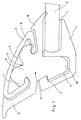
- Fig. 1 shows a schematic side view of an edge of a window area of a window area of a motor vehicle.
- a glass pane of the window is designated 3.
- a frame profile 4 made of relatively hard material is glued to the window glass 3 made of glass.
- the connecting profile 4 has a molded-in recess 17, and has an integrally formed locking lug 9 in the region of the upper opening edge.
- the profile part 1 is made separately from soft elastic material with a hardness of 30 to 90 Shore A.
- the profile part 1 has a head portion 10 which can be pressed into the recess 17 and locked with the locking lug 9.
- the profile part 1 is pressed into the receptacle 6 at the bottom of a trim strip 2 made of metal.
- the latching noses 7 and 8 deform due to the acting squeezing pressure until the foot portion 11 snaps into the receptacle.
- the recess denoted here by 13 is formed, which increases the crushing deformability of the profile part 1.
- Fig. 2 shows a unit formed by joining decorative strip 2 and profile part 1. Same components are given the same reference numbers as in Fig. 1 designated.
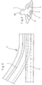
- Fig. 3 shows a schematic side view and illustrates how the profile part 1 is linked to the decorative profile 2 by the force F, the molded part 1 is loaded in Einknüpf Switzerland.
Landscapes
- Engineering & Computer Science (AREA)
- Mechanical Engineering (AREA)
- Window Of Vehicle (AREA)
- Seal Device For Vehicle (AREA)
- Vehicle Interior And Exterior Ornaments, Soundproofing, And Insulation (AREA)
Description
- Die Erfindung betrifft ein Verfahren zur Anordnung und Befestigung einer Zierleiste im Bereich eines Fensters eines Kraftfahrzeugs, bei dem die Zierleiste mit einem als Zierleistenträger dienenden Profil verbunden wird und anschließend das derart vorbereitete Profilteil mit einem im Bereich des Fensters ortsfest angeordneten Verbindungsprofil verbunden wird.
- Es ist bereits vorgeschlagen worden, Zierleisten mit einem als Zierleistenträger dienenden Profilteil zu verbinden und daß so vorbereitete Profilteil anschließend mit einem im Bereich des Fensters, entweder an der Karosserie oder an der Fensterscheibe aus Glas befestigten Verbindungsprofil zu verbinden.
- Die Befestigung des Verbindungsprofils kann dabei z.B. mittels Verkleben, Verrasten mit vorher angebrachten Clips, Druckknöpfen, Klammern und dergleichen Hilfsmitteln verwirklicht werden.
- Zierleisten sind zumeist Profilschienen aus Metall, z.B. Stahlblech oder Aluminium, mit einer Materialstärke von ca. 1 mm. Die Zierleisten sind aus metallischem Werkstoff gestanzt, geprägt, gewalzt oder gezogen und an der sichtseitigen Oberfläche zumeist poliert oder auch verchromt.
- Die Verbindung der bekannten Zierleisten mit einem die Zierleisten tragenden Basisteil, z.B. dem als Profilträger vorgeschlagenen Profilteil, erfolgt ebenfalls durch Kleber oder Verrasten, wobei mehr oder weniger aufwendige Montagevorgänge abzuwickeln sind, insbesondere auch zur Anbringung von vorgefertigten Clipsen, Klammern oder Steckern und dergleichen Befestigungsmitteln aus z.B. Kunststoff.
- Ein gattungsbildendes Verfahren ist aus der
DE 10 2004 035 680 A1 bekannt. - Der Erfindung liegt die Aufgabe zugrunde, eine Zierleiste im Bereich eines Fensters ohne zusätzliche Befestigungsmittel wie Kleber, Clipse, Klammern und dergleichen anzuordnen und zu befestigen.
- Diese Aufgabe ist erfindungsgemäß durch die Maßnahmen gemäß dem Patentanspruch 1 gelöst.
- Weiterbildungen und vorteilhafte Ausgestaltungen ergeben sich aus den Ansprüchen 2 und 3.
- Dadurch, daß als Werkstoff für das als Zierleistenträger eingesetzte Profilteil ein weichelastisches Material wie z.B. TPE, Weich-PVC, PU oder Gummi mit einer Härte von 30 bis 90 Shore A verwendet wird, läßt sich der Fußbereich des daraus geformten Profilteils mit entsprechendem Kraftaufwand in eine Aufnahme der Zierleiste quetschen, womit die Verbindung hergestellt ist. Die Aufnahme befindet sich an der sichtseitigen Oberfläche der Zierleiste abgekehrten Unterseite und kann z.B. dadurch gebildet sein, daß die Längsränder eines Metallstreifens, der für die Zierleiste verwendet wird, nach innen gegen die Unterseite mehr oder weniger umgebogen werden, sodaß an den Längsrändern des als Zierleiste eingesetzten Metallstreifens in etwa Hinterschneidungen ähnliche Kanten vorhanden sind, welche die Aufnahme begrenzen.
- Dadurch ist unter den umgebogenen Längsrändern ein Aufnahme-Raum vorhanden, der begrenzt wird von der Unterseitenfläche der Zierleiste, welche ihrer sichtseitigen Oberfläche abgekehrt ist, und den zurückgebogenen Längsrändern der Zierleiste.
- Selbstverständlich ist es auch möglich, durch andere Maßnahmen eine entsprechende Aufnahme an der Unterseite einer Zierleiste auszubilden. So kann z.B. die Zierleiste auch ein aus Aluminium extrudiertes Kammerprofil sein, bei der eine nach außen offene Kammer die Funktion der Aufnahme erfüllen kann.
- Das Profilteil hat eine Querschnittsform, bei der ein Fußbereich vorhanden ist, der eine z.B. etwa pilzkopfartige Form aufweist.
- Dieser pilzkopfförmige Fußbereich läßt sich erfindungsgemäß mit entsprechender Druckkraft in die enge Aufnahme quetschen, wodurch das Profilteil und die Zierleiste miteinander verbunden sind. Das Profilteil kann bereichsweise nacheinander mit der Druckkraft beaufschlagt werden, sodaß das weichelastische Profilteil mit der Aufnahme bzw. letztendlich mit der Zierleiste nahezu "verknüpft" wird.
- Das Formteil wird mit seinem Fußbereich praktisch in die Aufnahme der Zierleiste "hineingerollt", wobei dazu auch eine von außen führbare und dabei gegen das Profilteil drückbare Rolle benutzt werden könnte.
- Durch die Quetschung des weichelastischen Fußbereiches verformt sich dieser Abschnitt des Profilteils soweit, daß er in die Aufnahme der Zierleiste einfügbar ist. Sobald der Quetschdruck aufgehoben ist, springt der verformte Fußbereich in seine ursprüngliche Form elastisch zurück und ist hinter den vorspringenden Längsrändern der Zierleiste, welche die Aufnahme begrenzen, eingeschnappt und verriegelt bzw. festgesetzt.
- Die Zierleiste ist dadurch mit dem Profilteil ohne zusätzliche Hilfsmittel verbunden. Profilteil und Zierleiste bilden eine Baueinheit, die weiterer Verwendung zugeführt werden kann.
- Diese weitere Verwendung besteht darin, daß die erfindungsgemäße Baueinheit aus Zierleiste und Profilteil, anschließend mittels eines Verbindungsprofils im Bereich eines Fensters angeordnet und befestigt wird.
- Dies erfolgt dadurch, daß an dem Profilteil neben der Anformung seines Fußbereichs auch noch eine Anformung eines Kopfbereichs angeordnet ist. Der Kopfbereich kann ebenfalls pilzkopfartige Querschnittsform aufweisen, womit der Kopfbereich mit dem Verbindungsprofil auch wieder formschlüssig verrastbar ist. Dazu weist das Verbindungsprofil entsprechende Vertiefungen auf, in welche der Kopfbereich gefügt und damit verrastet werden kann.
- Das Fügen des Kopfbereiches in die zugeordnete Vertiefung ist ebenfalls ein Vorgang, bei den mit Quetschdrücken gearbeitet wird, mit der Wirkung, daß der in die Vertiefung eingefügte Kopfbereich des Profilteils anschließend kaum noch verformbar ist, weil er durch den quetschenden Haltedruck, der sowohl auf seinen Fußbereich als auch gleichzeitig auf seinen Kopfbereich wirkt, nahezu fest und unverformbar geworden ist, zumal die einfassenden Oberflächen der Aufnahme der Zierleiste und der Vertiefung des Verbindungsprofils durch ihre Funktion, auch ein Widerlager für die Druckkräfte zu bilden eine weitere Zusammenquetschung des Materials des Profilteils behindern dürften.
- Die Fähigkeit des Materials, bei Quetschverformung ausweichen zu können, vermindert sich proportional zum wachsenden Quetschdruck während der Zusammenfügung der Bauteile. Das ist auch bei der Befestigung der Zierleiste an dem Profilteil der Fall.
- Um die aufzuwendenden Druckkräfte für die Quetschungen nicht zu groß werden zu lassen, ist nach einer vorteilhaften Weiterbildung vorgesehen, daß in die Außenflächen des Profilteils, insbesondere in die Außenflächen von Fußbereich und Kopfbereich des Profilteils, Ausnehmungen eingeformt werden, durch welche ihre Quetschverformbarkeit gesteigert wird.
- Das quetschverformte Material kann sich in die jeweilige Ausnehmung hinein verformen, wobei innerer Quetschdruck, der eine weitere Verformung behindern könnte, teilweise wieder abgebaut werden kann.
- Für z.B. ein Recyclingverfahren, ist die erfindungsgemäß befestigte Zierleiste mit besonderem Vorteil auch nur dann demontierbar, wenn der Quetschdruck auf den Kopfbereich des Profilteils aufgehoben wird. Dies kann dadurch erfolgen, daß der Kopfbereich des Profilteils aus der Vertiefung im Verbindungsprofil herausgezogen wird. Danach läßt sich die Zierleiste aus dem nunmehr wieder als frei handhabbare Baueinheit vorliegenden Profilteil mit verhältnismäßig geringem Aufwand herausschälen.
- Ein Ausführungsbeispiel, aus dem sich weitere erfinderische Merkmale ergeben, ist in der Zeichnung dargestellt. Es zeigen:
- Fig. 1:
- eine schematische Seitenansicht eines Fensterbereichs eines Kraftfahrzeugs im Schnitt,
- Fig. 2:
- eine Seitenansicht einer aus Profilteil und daran befestigter Zierleiste bestehenden Baueinheit und
- Fig. 3:
- eine schematische seitliche Ansicht der Zierleiste im Moment der Zusammenfügung bzw. Verbindung mit einem Profilteil zur Bildung der Baueinheit gemäß
Fig. 2 . -
Fig. 1 zeigt in einer schematischen Seitenansicht einen Rand eines Fensterbereichs eines Fensterbereichs eines Kraftfahrzeugs. Eine Glasscheibe des Fensters ist mit 3 bezeichnet. Mit Kleber 5 ist ein Rahmenprofil 4 aus relativ hartem Werkstoff an die Fensterscheibe 3 aus Glas geklebt. - Das Verbindungsprofil 4 weist eine eingeformte Vertiefung 17 auf, und hat im Bereich des oberen Öffnungsrandes eine angeformte Rastnase 9.
- Das Profilteil 1 ist separat aus weichelastischem Material mit einer Härte von 30 bis 90 Shore A gefertigt. Das Profilteil 1 weist einen Kopfbereich 10 auf, der in die Vertiefung 17 eindrückbar und mit der Rastnase 9 verrastbar ist.
- Mit einem Fußbereich 11, der durch seitliche Rastnasen 7 und 8 begrenzt ist, ist das Profilteil 1 in die Aufnahme 6 an der Unterseite einer Zierleiste 2 aus Metall gedrückt. Durch das Eindrücken in die Aufnahme 6 verformen sich die Rastnasen 7 und 8 aufgrund des einwirkenden Quetschdruckes bis der Fußbereich 11 in die Aufnahme schnappt.
- Mit 12 sind seitliche Ausgleichslippen des Profilteils 1 bezeichnet.
- In die Außenfläche des Fußbereichs 11 ist die hier mit 13 bezeichnete Ausnehmung eingeformt, welche die Quetschverformbarkeit des Profilteils 1 steigert.
-
Fig. 2 zeigt eine durch Zusammenfügung von Zierleiste 2 und Profilteil 1 gebildete Baueinheit. Gleiche Bauteile sind mit gleichen Bezugszahlen wie inFig. 1 bezeichnet. -
Fig. 3 zeigt eine schematische Seitenansicht und verdeutlicht, wie das Profilteil 1 mit dem Zierprofil 2 verknüpft wird, indem mit der Kraft F das Formteil 1 im Einknüpfbereich belastet wird. - Sobald daß die aus derart zusammengefügtem Profilteil 1 und Zierleiste 2 gebildete Baueinheit vorliegt, kann die Anordnung und Befestigung vorgenommen werden, wie es in
Fig. 1 dargestellt ist.
Claims (3)
- Verfahren zur Anordnung und Befestigung einer Zierleiste (2) im Bereich eines Fensters eines Kraftfahrzeuges, bei dem die Zierleiste mit einem als Zierleistenträger dienenden Profilteil (1) verbunden wird und anschließend das derart vorbereitete Profilteil mit einem an einer Glasscheibe (3) des Fensters
ortsfest angeordneten Verbindungsprofil (4) verbunden wird,
dadurch gekennzeichnet,
daß als Werkstoff für das Profilteil (1) ein weichelastisches Material verwendet wird,
daß ein vorstehender Fußbereich (11) des Profilteils (1) mit Druckkraft von außen beaufschlagt und unter Verformung seiner Außenkontur in eine enge Aufnahme (6) der Zierleiste (2) gequetscht wird, die sich an der der Sichtseite abgekehrten Unterseite der Zierleiste (2) befindet,
und daß danach die Druckkraftbeaufschlagung aufgehoben und der aus der Aufnahme (6) vorstehende Kopfbereich des Profilteils (1) in eine Vertiefung (17) des Verbindungsprofils (4) eingefügt und damit formschlüssig verrastet wird. - Verfahren nach Anspruch 1, dadurch gekennzeichnet, daß als Werkstoff für das Profilteil (1) Kunststoffmaterial mit einer Härte von 30 bis 90 Shore A verwendet wird.
- Verfahren nach einem der Ansprüche 1 und 2, dadurch gekennzeichnet, daß in die Außenfläche des Profilteils (1), insbesondere in die Außenflächen von Fußbereich (11) und Kopfbereich (10) des Profilteils (1) Ausnehmungen (13) eingeformt werden, durch welche ihre Quetschverformbarkeit gesteigert wird.
Applications Claiming Priority (2)
| Application Number | Priority Date | Filing Date | Title |
|---|---|---|---|
| DE102008026923A DE102008026923A1 (de) | 2008-06-05 | 2008-06-05 | Verfahren zur Anordnung und Befestigung einer Zierleiste im Bereich eines Fensters eines Kraftfahrzeugs |
| PCT/DE2009/000766 WO2009146682A1 (de) | 2008-06-05 | 2009-06-03 | Verfahren zur anordnung und befestigung einer zierleiste im bereich eines fensters eines kraftfahrzeugs |
Publications (2)
| Publication Number | Publication Date |
|---|---|
| EP2285627A1 EP2285627A1 (de) | 2011-02-23 |
| EP2285627B1 true EP2285627B1 (de) | 2011-10-26 |
Family
ID=41108240
Family Applications (1)
| Application Number | Title | Priority Date | Filing Date |
|---|---|---|---|
| EP09757116A Not-in-force EP2285627B1 (de) | 2008-06-05 | 2009-06-03 | Verfahren zur anordnung und befestigung einer zierleiste im bereich eines fensters eines kraftfahrzeugs |
Country Status (5)
| Country | Link |
|---|---|
| US (1) | US20110179628A1 (de) |
| EP (1) | EP2285627B1 (de) |
| AT (1) | ATE530389T1 (de) |
| DE (1) | DE102008026923A1 (de) |
| WO (1) | WO2009146682A1 (de) |
Families Citing this family (10)
| Publication number | Priority date | Publication date | Assignee | Title |
|---|---|---|---|---|
| DE102008060448A1 (de) * | 2008-12-04 | 2010-06-17 | CADEA-Gesellschaft für Anwendung und Realisierung computerunterstützter Systeme mbH | Scheibeneinfassung |
| DE202010009720U1 (de) | 2009-03-17 | 2011-02-10 | Pilkington Italia S.P.A. | Fahrzeugverkleidung mit einer daran montierten Zierleiste |
| GB201103086D0 (en) | 2011-02-23 | 2011-04-06 | Pilkington Automotive D Gmbh | Vehicle glazing |
| DE102012105247A1 (de) * | 2012-01-30 | 2013-08-01 | Fkt Gmbh | Bauteil mit einem Kernprofilelement |
| CN102996021B (zh) * | 2012-11-20 | 2015-03-25 | 福耀玻璃工业集团股份有限公司 | 一种中间嵌件和包括该中间嵌件的玻璃窗 |
| WO2014188004A1 (de) | 2013-05-24 | 2014-11-27 | Cooper Standard GmbH | Dichtungsanordnung sowie zierleiste und trägerprofil für eine dichtungsanordnung |
| CN103754170B (zh) | 2014-01-07 | 2016-05-18 | 福耀玻璃工业集团股份有限公司 | 一种中间嵌件和玻璃窗 |
| TWI751984B (zh) * | 2015-10-22 | 2022-01-11 | 德商Epg德國工程奈米產品股份有限公司 | 用於輕型金屬、尤其是鋁的抗鹼性塗層 |
| DE102016006209A1 (de) | 2016-05-19 | 2017-11-23 | GM Global Technology Operations LLC (n. d. Ges. d. Staates Delaware) | Kraftfahrzeug-Zierleiste |
| CN109591558B (zh) * | 2019-01-11 | 2020-08-07 | 浙江兴宇汽车零部件有限公司 | 一种汽车用车窗玻璃导槽 |
Family Cites Families (9)
| Publication number | Priority date | Publication date | Assignee | Title |
|---|---|---|---|---|
| DE7640877U1 (de) * | 1900-01-01 | Gebr. Happich Gmbh, 5600 Wuppertal | ||
| US3517473A (en) * | 1967-11-02 | 1970-06-30 | Textron Inc | Vehicle trim strip with elastomeric bumper insert |
| US3451716A (en) * | 1968-05-28 | 1969-06-24 | Gen Motors Corp | Retainer assembly for vehicle bodies |
| DE2010564A1 (de) * | 1970-03-06 | 1971-09-16 | Daimler Benz Ag | Vorrichtung zum Halten einer Zier leiste an Kraftwagenfenstern |
| US5233758A (en) * | 1991-09-03 | 1993-08-10 | General Motors Corporation | Method of making a one-piece modular door frame glass run channel |
| ES1036619Y (es) * | 1997-03-05 | 1998-03-01 | Pertecsa | Moldura vierteaguas para automoviles. |
| DE19730095C2 (de) * | 1997-07-14 | 2000-05-04 | Wagon Automotive Gmbh | Zierteil für ein Kraftfahrzeug |
| DE102004035680B4 (de) * | 2004-07-22 | 2015-12-31 | Henniges Automotive Gmbh & Co. Kg | Plattenförmiges Element mit an einem Elementrand angeordneten Profilteil |
| DE102006002556B3 (de) * | 2006-01-10 | 2007-08-30 | Decoma (Germany) Gmbh | Verbindungselement |
-
2008
- 2008-06-05 DE DE102008026923A patent/DE102008026923A1/de not_active Withdrawn
-
2009
- 2009-06-03 EP EP09757116A patent/EP2285627B1/de not_active Not-in-force
- 2009-06-03 WO PCT/DE2009/000766 patent/WO2009146682A1/de not_active Ceased
- 2009-06-03 AT AT09757116T patent/ATE530389T1/de active
- 2009-06-03 US US12/737,055 patent/US20110179628A1/en not_active Abandoned
Also Published As
| Publication number | Publication date |
|---|---|
| ATE530389T1 (de) | 2011-11-15 |
| DE102008026923A1 (de) | 2009-12-10 |
| EP2285627A1 (de) | 2011-02-23 |
| WO2009146682A1 (de) | 2009-12-10 |
| US20110179628A1 (en) | 2011-07-28 |
Similar Documents
| Publication | Publication Date | Title |
|---|---|---|
| EP2285627A1 (de) | Verfahren zur anordnung und befestigung einer zierleiste im bereich eines fensters eines kraftfahrzeugs | |
| DE3618278C2 (de) | ||
| DE3300660C2 (de) | Befestigungsvorrichtung für Fensterscheiben | |
| DE3517936A1 (de) | Dicht- und/oder abdeckstreifen | |
| WO1995021749A1 (de) | Verfahren für die herstellung und den einbau einer glasscheibe mit rahmen, insbesondere an einem fahrzeugteil | |
| DE20008555U1 (de) | Abdichtungs-Anordnung für Fahrzeugscheiben | |
| DE3426355A1 (de) | Fensterprofil | |
| DE102008050130A1 (de) | Automobil-Glasscheibe | |
| DE102011014540A1 (de) | Profildichtung mit Zierleiste für ein Fahrzeug | |
| DE102007043218B3 (de) | Abdeckleiste | |
| DE69401238T2 (de) | Türdichtung für Motorfahrzeug | |
| DE102016125814A1 (de) | Zierteil | |
| DE10038200B4 (de) | Fensterdichtung zur Anbringung an einer Kraftfahrzeugtüre | |
| DE102016110276A1 (de) | Dichtung für eine versenkbare Fensterscheibe eines Fahrzeugtürfensters | |
| EP1858720B1 (de) | Dichtungsanordnung | |
| EP3085563A1 (de) | Spritzgegossene wasserablaufleiste und anordnung für eine fahrzeugverkleidung | |
| DE602004028666C5 (de) | Stützbänder und verfahren | |
| DE10001430B4 (de) | Anordnung zur lösbaren Befestigung einer Abdeckung an einer Scheibe, insbesondere einer Wasserkastenabdeckung an einer Kraftfahrzeug-Frontscheibe | |
| DE102017211291B4 (de) | Fensterschachtleistenanordnung sowie Verfahren zum Herstellen einer Fensterschachtleistenanordnung | |
| DE202008007706U1 (de) | Dichtungsprofil | |
| DE202005021480U1 (de) | Verbindungselemente für Platten, insbesondere aus Glas, zur Befestigung derselben und derart ausgerüstete Platten | |
| DE102005013005A1 (de) | Dichtung, insbesondere zum Abdichten der Karosserie eines Kraftfahrzeugs | |
| DE10053678B4 (de) | Anordnung aus einer Fahrzeugfensterscheibe und einem anschließenden Abdeckelement | |
| DE3873898T2 (de) | Fensterscheibenpositioniervorrichtung. | |
| DE202006020836U1 (de) | Dichtband |
Legal Events
| Date | Code | Title | Description |
|---|---|---|---|
| PUAI | Public reference made under article 153(3) epc to a published international application that has entered the european phase |
Free format text: ORIGINAL CODE: 0009012 |
|
| AK | Designated contracting states |
Kind code of ref document: A1 Designated state(s): AT BE BG CH CY CZ DE DK EE ES FI FR GB GR HR HU IE IS IT LI LT LU LV MC MK MT NL NO PL PT RO SE SI SK TR |
|
| AX | Request for extension of the european patent |
Extension state: AL BA RS |
|
| 17P | Request for examination filed |
Effective date: 20101124 |
|
| GRAP | Despatch of communication of intention to grant a patent |
Free format text: ORIGINAL CODE: EPIDOSNIGR1 |
|
| DAX | Request for extension of the european patent (deleted) | ||
| GRAS | Grant fee paid |
Free format text: ORIGINAL CODE: EPIDOSNIGR3 |
|
| GRAA | (expected) grant |
Free format text: ORIGINAL CODE: 0009210 |
|
| AK | Designated contracting states |
Kind code of ref document: B1 Designated state(s): AT BE BG CH CY CZ DE DK EE ES FI FR GB GR HR HU IE IS IT LI LT LU LV MC MK MT NL NO PL PT RO SE SI SK TR |
|
| REG | Reference to a national code |
Ref country code: GB Ref legal event code: FG4D Free format text: NOT ENGLISH |
|
| REG | Reference to a national code |
Ref country code: CH Ref legal event code: EP |
|
| REG | Reference to a national code |
Ref country code: IE Ref legal event code: FG4D |
|
| REG | Reference to a national code |
Ref country code: DE Ref legal event code: R096 Ref document number: 502009001749 Country of ref document: DE Effective date: 20111222 |
|
| REG | Reference to a national code |
Ref country code: NL Ref legal event code: VDEP Effective date: 20111026 |
|
| LTIE | Lt: invalidation of european patent or patent extension |
Effective date: 20111026 |
|
| PG25 | Lapsed in a contracting state [announced via postgrant information from national office to epo] |
Ref country code: IS Free format text: LAPSE BECAUSE OF FAILURE TO SUBMIT A TRANSLATION OF THE DESCRIPTION OR TO PAY THE FEE WITHIN THE PRESCRIBED TIME-LIMIT Effective date: 20120226 Ref country code: NO Free format text: LAPSE BECAUSE OF FAILURE TO SUBMIT A TRANSLATION OF THE DESCRIPTION OR TO PAY THE FEE WITHIN THE PRESCRIBED TIME-LIMIT Effective date: 20120126 Ref country code: LT Free format text: LAPSE BECAUSE OF FAILURE TO SUBMIT A TRANSLATION OF THE DESCRIPTION OR TO PAY THE FEE WITHIN THE PRESCRIBED TIME-LIMIT Effective date: 20111026 |
|
| PG25 | Lapsed in a contracting state [announced via postgrant information from national office to epo] |
Ref country code: PT Free format text: LAPSE BECAUSE OF FAILURE TO SUBMIT A TRANSLATION OF THE DESCRIPTION OR TO PAY THE FEE WITHIN THE PRESCRIBED TIME-LIMIT Effective date: 20120227 Ref country code: NL Free format text: LAPSE BECAUSE OF FAILURE TO SUBMIT A TRANSLATION OF THE DESCRIPTION OR TO PAY THE FEE WITHIN THE PRESCRIBED TIME-LIMIT Effective date: 20111026 Ref country code: SE Free format text: LAPSE BECAUSE OF FAILURE TO SUBMIT A TRANSLATION OF THE DESCRIPTION OR TO PAY THE FEE WITHIN THE PRESCRIBED TIME-LIMIT Effective date: 20111026 Ref country code: HR Free format text: LAPSE BECAUSE OF FAILURE TO SUBMIT A TRANSLATION OF THE DESCRIPTION OR TO PAY THE FEE WITHIN THE PRESCRIBED TIME-LIMIT Effective date: 20111026 Ref country code: PL Free format text: LAPSE BECAUSE OF FAILURE TO SUBMIT A TRANSLATION OF THE DESCRIPTION OR TO PAY THE FEE WITHIN THE PRESCRIBED TIME-LIMIT Effective date: 20111026 Ref country code: LV Free format text: LAPSE BECAUSE OF FAILURE TO SUBMIT A TRANSLATION OF THE DESCRIPTION OR TO PAY THE FEE WITHIN THE PRESCRIBED TIME-LIMIT Effective date: 20111026 Ref country code: GR Free format text: LAPSE BECAUSE OF FAILURE TO SUBMIT A TRANSLATION OF THE DESCRIPTION OR TO PAY THE FEE WITHIN THE PRESCRIBED TIME-LIMIT Effective date: 20120127 Ref country code: SI Free format text: LAPSE BECAUSE OF FAILURE TO SUBMIT A TRANSLATION OF THE DESCRIPTION OR TO PAY THE FEE WITHIN THE PRESCRIBED TIME-LIMIT Effective date: 20111026 |
|
| REG | Reference to a national code |
Ref country code: IE Ref legal event code: FD4D |
|
| PG25 | Lapsed in a contracting state [announced via postgrant information from national office to epo] |
Ref country code: CY Free format text: LAPSE BECAUSE OF FAILURE TO SUBMIT A TRANSLATION OF THE DESCRIPTION OR TO PAY THE FEE WITHIN THE PRESCRIBED TIME-LIMIT Effective date: 20111026 |
|
| PG25 | Lapsed in a contracting state [announced via postgrant information from national office to epo] |
Ref country code: SK Free format text: LAPSE BECAUSE OF FAILURE TO SUBMIT A TRANSLATION OF THE DESCRIPTION OR TO PAY THE FEE WITHIN THE PRESCRIBED TIME-LIMIT Effective date: 20111026 Ref country code: EE Free format text: LAPSE BECAUSE OF FAILURE TO SUBMIT A TRANSLATION OF THE DESCRIPTION OR TO PAY THE FEE WITHIN THE PRESCRIBED TIME-LIMIT Effective date: 20111026 Ref country code: IE Free format text: LAPSE BECAUSE OF FAILURE TO SUBMIT A TRANSLATION OF THE DESCRIPTION OR TO PAY THE FEE WITHIN THE PRESCRIBED TIME-LIMIT Effective date: 20111026 Ref country code: CZ Free format text: LAPSE BECAUSE OF FAILURE TO SUBMIT A TRANSLATION OF THE DESCRIPTION OR TO PAY THE FEE WITHIN THE PRESCRIBED TIME-LIMIT Effective date: 20111026 Ref country code: BG Free format text: LAPSE BECAUSE OF FAILURE TO SUBMIT A TRANSLATION OF THE DESCRIPTION OR TO PAY THE FEE WITHIN THE PRESCRIBED TIME-LIMIT Effective date: 20120126 Ref country code: DK Free format text: LAPSE BECAUSE OF FAILURE TO SUBMIT A TRANSLATION OF THE DESCRIPTION OR TO PAY THE FEE WITHIN THE PRESCRIBED TIME-LIMIT Effective date: 20111026 |
|
| PLBI | Opposition filed |
Free format text: ORIGINAL CODE: 0009260 |
|
| PG25 | Lapsed in a contracting state [announced via postgrant information from national office to epo] |
Ref country code: IT Free format text: LAPSE BECAUSE OF FAILURE TO SUBMIT A TRANSLATION OF THE DESCRIPTION OR TO PAY THE FEE WITHIN THE PRESCRIBED TIME-LIMIT Effective date: 20111026 Ref country code: RO Free format text: LAPSE BECAUSE OF FAILURE TO SUBMIT A TRANSLATION OF THE DESCRIPTION OR TO PAY THE FEE WITHIN THE PRESCRIBED TIME-LIMIT Effective date: 20111026 |
|
| PLAX | Notice of opposition and request to file observation + time limit sent |
Free format text: ORIGINAL CODE: EPIDOSNOBS2 |
|
| 26 | Opposition filed |
Opponent name: PILKINGTON GROUP LIMITED Effective date: 20120726 |
|
| REG | Reference to a national code |
Ref country code: DE Ref legal event code: R026 Ref document number: 502009001749 Country of ref document: DE Effective date: 20120726 |
|
| PLBB | Reply of patent proprietor to notice(s) of opposition received |
Free format text: ORIGINAL CODE: EPIDOSNOBS3 |
|
| BERE | Be: lapsed |
Owner name: HENNIGES AUTOMOTIVE G.M.B.H. & CO. KG Effective date: 20120630 |
|
| PG25 | Lapsed in a contracting state [announced via postgrant information from national office to epo] |
Ref country code: MC Free format text: LAPSE BECAUSE OF NON-PAYMENT OF DUE FEES Effective date: 20120630 |
|
| PG25 | Lapsed in a contracting state [announced via postgrant information from national office to epo] |
Ref country code: MK Free format text: LAPSE BECAUSE OF FAILURE TO SUBMIT A TRANSLATION OF THE DESCRIPTION OR TO PAY THE FEE WITHIN THE PRESCRIBED TIME-LIMIT Effective date: 20111026 |
|
| REG | Reference to a national code |
Ref country code: FR Ref legal event code: ST Effective date: 20130228 |
|
| PG25 | Lapsed in a contracting state [announced via postgrant information from national office to epo] |
Ref country code: ES Free format text: LAPSE BECAUSE OF FAILURE TO SUBMIT A TRANSLATION OF THE DESCRIPTION OR TO PAY THE FEE WITHIN THE PRESCRIBED TIME-LIMIT Effective date: 20120206 Ref country code: BE Free format text: LAPSE BECAUSE OF NON-PAYMENT OF DUE FEES Effective date: 20120630 Ref country code: FR Free format text: LAPSE BECAUSE OF NON-PAYMENT OF DUE FEES Effective date: 20120702 |
|
| PG25 | Lapsed in a contracting state [announced via postgrant information from national office to epo] |
Ref country code: FI Free format text: LAPSE BECAUSE OF FAILURE TO SUBMIT A TRANSLATION OF THE DESCRIPTION OR TO PAY THE FEE WITHIN THE PRESCRIBED TIME-LIMIT Effective date: 20111026 |
|
| PG25 | Lapsed in a contracting state [announced via postgrant information from national office to epo] |
Ref country code: MT Free format text: LAPSE BECAUSE OF FAILURE TO SUBMIT A TRANSLATION OF THE DESCRIPTION OR TO PAY THE FEE WITHIN THE PRESCRIBED TIME-LIMIT Effective date: 20111026 |
|
| REG | Reference to a national code |
Ref country code: CH Ref legal event code: PL |
|
| GBPC | Gb: european patent ceased through non-payment of renewal fee |
Effective date: 20130603 |
|
| PG25 | Lapsed in a contracting state [announced via postgrant information from national office to epo] |
Ref country code: LI Free format text: LAPSE BECAUSE OF NON-PAYMENT OF DUE FEES Effective date: 20130630 Ref country code: TR Free format text: LAPSE BECAUSE OF FAILURE TO SUBMIT A TRANSLATION OF THE DESCRIPTION OR TO PAY THE FEE WITHIN THE PRESCRIBED TIME-LIMIT Effective date: 20111026 Ref country code: GB Free format text: LAPSE BECAUSE OF NON-PAYMENT OF DUE FEES Effective date: 20130603 Ref country code: CH Free format text: LAPSE BECAUSE OF NON-PAYMENT OF DUE FEES Effective date: 20130630 |
|
| PG25 | Lapsed in a contracting state [announced via postgrant information from national office to epo] |
Ref country code: LU Free format text: LAPSE BECAUSE OF NON-PAYMENT OF DUE FEES Effective date: 20120603 |
|
| PG25 | Lapsed in a contracting state [announced via postgrant information from national office to epo] |
Ref country code: HU Free format text: LAPSE BECAUSE OF FAILURE TO SUBMIT A TRANSLATION OF THE DESCRIPTION OR TO PAY THE FEE WITHIN THE PRESCRIBED TIME-LIMIT Effective date: 20090603 |
|
| REG | Reference to a national code |
Ref country code: AT Ref legal event code: MM01 Ref document number: 530389 Country of ref document: AT Kind code of ref document: T Effective date: 20140603 |
|
| PG25 | Lapsed in a contracting state [announced via postgrant information from national office to epo] |
Ref country code: AT Free format text: LAPSE BECAUSE OF NON-PAYMENT OF DUE FEES Effective date: 20140603 |
|
| PLCK | Communication despatched that opposition was rejected |
Free format text: ORIGINAL CODE: EPIDOSNREJ1 |
|
| REG | Reference to a national code |
Ref country code: DE Ref legal event code: R100 Ref document number: 502009001749 Country of ref document: DE |
|
| PLBN | Opposition rejected |
Free format text: ORIGINAL CODE: 0009273 |
|
| STAA | Information on the status of an ep patent application or granted ep patent |
Free format text: STATUS: OPPOSITION REJECTED |
|
| 27O | Opposition rejected |
Effective date: 20160214 |
|
| REG | Reference to a national code |
Ref country code: DE Ref legal event code: R082 Ref document number: 502009001749 Country of ref document: DE Representative=s name: BARDEHLE PAGENBERG PARTNERSCHAFT MBB PATENTANW, DE |
|
| PGFP | Annual fee paid to national office [announced via postgrant information from national office to epo] |
Ref country code: DE Payment date: 20201230 Year of fee payment: 12 |
|
| REG | Reference to a national code |
Ref country code: DE Ref legal event code: R119 Ref document number: 502009001749 Country of ref document: DE |
|
| PG25 | Lapsed in a contracting state [announced via postgrant information from national office to epo] |
Ref country code: DE Free format text: LAPSE BECAUSE OF NON-PAYMENT OF DUE FEES Effective date: 20220101 |
|
| REG | Reference to a national code |
Ref country code: DE Ref legal event code: R082 Ref document number: 502009001749 Country of ref document: DE |