EP2284815B1 - Alarmvorrichtung - Google Patents
Alarmvorrichtung Download PDFInfo
- Publication number
- EP2284815B1 EP2284815B1 EP09738663.5A EP09738663A EP2284815B1 EP 2284815 B1 EP2284815 B1 EP 2284815B1 EP 09738663 A EP09738663 A EP 09738663A EP 2284815 B1 EP2284815 B1 EP 2284815B1
- Authority
- EP
- European Patent Office
- Prior art keywords
- alarm
- alarm device
- section
- reception
- transmission
- Prior art date
- Legal status (The legal status is an assumption and is not a legal conclusion. Google has not performed a legal analysis and makes no representation as to the accuracy of the status listed.)
- Active
Links
Images


Classifications
-
- G—PHYSICS
- G08—SIGNALLING
- G08B—SIGNALLING OR CALLING SYSTEMS; ORDER TELEGRAPHS; ALARM SYSTEMS
- G08B25/00—Alarm systems in which the location of the alarm condition is signalled to a central station, e.g. fire or police telegraphic systems
- G08B25/009—Signalling of the alarm condition to a substation whose identity is signalled to a central station, e.g. relaying alarm signals in order to extend communication range
-
- G—PHYSICS
- G08—SIGNALLING
- G08B—SIGNALLING OR CALLING SYSTEMS; ORDER TELEGRAPHS; ALARM SYSTEMS
- G08B17/00—Fire alarms; Alarms responsive to explosion
-
- G—PHYSICS
- G08—SIGNALLING
- G08B—SIGNALLING OR CALLING SYSTEMS; ORDER TELEGRAPHS; ALARM SYSTEMS
- G08B29/00—Checking or monitoring of signalling or alarm systems; Prevention or correction of operating errors, e.g. preventing unauthorised operation
- G08B29/18—Prevention or correction of operating errors
- G08B29/181—Prevention or correction of operating errors due to failing power supply
-
- G—PHYSICS
- G08—SIGNALLING
- G08B—SIGNALLING OR CALLING SYSTEMS; ORDER TELEGRAPHS; ALARM SYSTEMS
- G08B17/00—Fire alarms; Alarms responsive to explosion
- G08B17/10—Actuation by presence of smoke or gases, e.g. automatic alarm devices for analysing flowing fluid materials by the use of optical means
- G08B17/11—Actuation by presence of smoke or gases, e.g. automatic alarm devices for analysing flowing fluid materials by the use of optical means using an ionisation chamber for detecting smoke or gas
- G08B17/113—Constructional details
Definitions
- the present invention relates to an alarm device that detects an anomaly such as fire and performs an alarm, and also wirelessly transmits a signal to other alarm devices to perform linked alarm output.
- Priority is claimed on Japanese Utility Model Application No. 2008-002727 and Japanese Utility Model Application No. 2008-002728 .
- alarm devices that emit an alarm upon detecting an anomaly such as a fire, gas leak or the like have become prevalent, and in recent years, there has been an increasing trend to perform monitoring for anomalies such as fires in every room by installing a plurality of alarm devices in a single residence (for example, refer to Patent Document 1).
- an alarm device that uses a conventional battery power supply, when the battery voltage has fallen to a limit voltage in which normal functionality is possible over 72 hours (three days), it is designed to detect a low battery, and output a short alarm sound such as a "beep" once a minute for example.
- Document WO 2006/044751 discloses an alarm device according the preamble of claim 1.
- the present invention has as its object to provide an alarm device that increases reliability by extending as much as possible the remaining time until a battery runs down even if a low battery alarm has been emitted.
- a alarm device of the present invention is provided according to claim 1.
- the low battery monitoring section may detect the voltage drop when the battery voltage has dropped to a limit voltage at which the normal function of the alarm device can be maintained over a predetermined remaining time.
- the aforementioned alarm device of the present invention when the battery voltage drops and a low battery is detected, due to changing the discontinuous reception cycle until then to a longer cycle, it is possible to reduce the average consumption current of the reception circuit section. As a result, the time until the battery runs down is extended, and even if a low battery is detected and an alarm is issued, it is possible to prevent as much as possible a non-alert state due to the battery running down while no one is present.
- FIG. 1 A and FIG 1B The exterior appearance of the wireless alarm device according to an example is shown in FIG. 1 A and FIG 1B , with FIG. 1A showing a front elevation, and FIG 1B showing a side elevation.
- an alarm device 10 of the present example is provided with a cover 12 and a main unit 14.
- a smoke detector section 16 in which openings that serve as smoke inlets are formed is arranged in the center of the cover 12, and when smoke from a fire reaches a predetermined density, it detects a fire.
- a sound hole 18 is provided on the lower left side of the smoke detector section 16 of the cover 12.
- a speaker is built in at the rear of the sound hole 18 and outputs an alarm sound or voice message through this sound hole 18.
- An alarm stop switch 20 is provided on the lower side of the smoke detector section 16. The alarm stop switch 20 also has a function as a check switch.
- An LED 22 as shown by the dotted line is arranged within the alarm stop switch 20.
- the LED 22 turns on, the light therefrom passes through the portion of the switch cover of the alarm stop switch 20, and so the turned on state of the LED 22 can be confirmed from outside.
- An mounting hook 15 is provided on the upper portion of the underside the main unit 14, and by screwing in a screw (not illustrated) into a wall of a room where it is to be installed, and attaching the mounting hook 15 onto this screw, it is possible to install the alarm device 10 on a wall.
- the alarm device 10 that is shown in FIG. 1A and FIG. 1B shows an example of the constitution that detects smoke from a fire with the smoke detector section 16, but in addition an alarm device that is provided with a thermistor that detects heat from a fire, or an alarm device that detects a gas leak besides a fire are included in the scope of the present invention.
- FIG. 2 is an explanatory drawing that shows the state of the alarm device of the present example installed in a residence.
- alarm devices 10-1 to 10-4 of the present example are installed in the kitchen, living room, master bedroom, and a child's room of a residence 24, and moreover, an alarm device 10-5 is installed in a garage 26 that is built outside.
- the alarm devices 10-1 to 10-5 are each provided with a function to mutually transmit and receive wirelessly an event signal, and the five alarm devices 10-1 to 10-5 constitute one group to perform fire monitoring of the entire residence 24.
- the alarm device 10-4 detects the fire and starts an alarm.
- the detection of the fire and starting of the alarm is called “alarm activation" in the alarm device.
- the alarm device 10-4 activates an alarm
- the alarm device 10-4 functions as the linked source, and transmits wirelessly the event signal that indicates a fire alarm activation to the other alarm devices 10-1 to 10-3 and 10-5 that serve as linked destinations.
- the other alarm devices 10-1 to 10-3 and 10-5 receive the event signal that indicates fire alarm activation from the alarm device 10-4 that is the linked source, they perform an alarm operation as linked destinations.
- the voice message "Woo Woo...The fire alarm has been activated. Please confirm" is output continuously.
- the linked destination alarm devices 10-1 to 10-3 and 10-5 the voice message "Woo Woo...Another fire alarm has been activated. Please confirm" is output continuously.
- the alarm stop switch 20 that is provided on the alarm device shown in FIG. 1A is operated, the stop process of the alarm sound is performed.
- the alarm devices 10-1 to 10-5 are provided with a low battery monitoring function that monitors the running down of the battery, and when it detects a low battery, for example, it intermittently outputs a "beep" alarm sound at a predetermined time interval, and reports that a failure has occurred.
- the alarm devices 10-1 to 10-5 monitor for a sensor failure besides a low battery, and when they detect a sensor failure, perform a linked alarm in the same manner as the low battery detection.
- FIG. 3 is a block diagram that shows the constitution of the alarm device of the present example.
- FIG. 3 shows in detail the circuit configuration of the alarm device 10-1, among the five alarm devices 10-1 to 10-5 shown in FIG. 2 .
- the alarm device 10-1 is provided with a CPU 28. Also, corresponding to this CPU 28, it is further provided with a wireless circuit section 30 that is provided with an antenna 31, a storage circuit section 32, a sensor section 34, an alert section 36, an operating section 38, and a battery power supply 40.
- the wireless circuit section 30 is provided with the transmission circuit 42 and the reception circuit 44, and is designed to be capable of wirelessly transmitting and receiving event signals to/from the other alarm devices 10-2 to 10-5.
- the wireless circuit section 30 in Japan it is preferable to adopt a constitution based on for example STD-30, which is known as the standard for specified low-power radio stations in the 400 MHz band (ARIB Standard for Radio Equipment for Radio Station of Low Power Security System), or STD-T67 (ARIB Standard for Telemeter, Telecontrol and Data Transmission Radio Equipment for Specified Low Power Radio Stations).
- the wireless circuit section 30 for places outside of Japan, it is preferable to adopt a constitution that is based on the standard for allocated radio stations of that region.
- the reception circuit 44 performs a discontinuous reception operation.
- the discontinuous reception cycle T12 of the reception circuit 44 is a cycle that is determined at the design stage of the alarm device, so as to lead to an average current consumption that ensures a battery life of for example 10 years.
- the transmission circuit 42 and the reception circuit 44 of the present embodiment stop the transmission and reception so as to extend the battery life by a control signal from the CPU 28 when a low battery is detected.
- a memory 46 is provided in the storage circuit section 32.
- a transmission source code 50 that serves as an ID (identifier) that specifies the alarm device, and a group code 52 for constituting a group that performs a linked alarm with a plurality of alarms as shown in FIG. 2 is housed in the memory 46.
- the transmission source code 50 the number of alarm devices to be provided domestically is calculated, and for example a code of 26 bits is used so that the same code does not overlap.
- the group code 52 is a code that is set so as to be common for the plurality of alarm devices that constitute a group, and when the group code that is included in the event signal from another alarm device that is received by the wireless circuit section 30 matches the group code 52 that is registered in the memory 46, that event signal is received as a valid signal and processed.
- the memory 46 is used in the storage circuit section 32, but a DIP switch may be provided instead of the memory 46, so that the transmission source code 50 and the group code 52 may be set by this DIP switch.
- the storage circuit section 32 that uses a DIP switch is preferred.
- the smoke detector section 16 is provided in the sensor section 34, and outputs a smoke detection signal corresponding to the smoke density to the CPU 28.
- a thermistor that detects the temperature from a fire may be provided.
- a gas leak sensor is provided in the sensor section 34.
- the speaker 56 and the LED 22 are provided in the alert section 36.
- the speaker 56 outputs a voice message from a speech synthesis circuit section that is not illustrated or an alarm sound.
- the alarm stop switch 20 is provided in the operating section 38. When the alarm stop switch 20 is operated, it is possible to stop the alarm sound that is sounding from the alarm device 10-1.
- the alarm stop switch 20 also doubles as a check switch in the present embodiment.
- the alarm stop switch 20 is in effect when the alert section 36 is outputting an alarm sound from the speaker 56.
- the alarm stop switch 20 functions as a check switch, and when the check switch is pushed, a voice message for inspection is output from the alert section 36.
- the battery power supply 40 uses for example alkaline dry cells of a predetermined number, and regarding the battery capacity, a battery service life of about 10 years is ensured due to the reduced power consumption of the entire circuit section including the wireless circuit section 30 in the alarm device 10-1.
- an anomaly monitoring section 58 and a low battery monitoring section 60 are provided as functions that are realized by the execution of programs.
- the anomaly monitoring section 58 causes the repeated output of, for example, "Woo Woo...The fire alarm has been activated. Please confirm" as the voice message that is the alarm sound indicating the linked source from the speaker 58 of the alert section 36, and causes the transmission of an event signal that indicates fire alarm activation from the antenna 31 to the other alarm devices 10-2 to 10-5 by the transmission circuit 42 of the wireless circuit section 30.
- the anomaly monitoring section 58 causes an alarm sound indicating the linked destination, for example, the voice message "Woo Woo...Another fire alarm has been activated. Please confirm" to be output continuously from the speaker 56 of the alert section 36.
- the LED 22 of the alert section 36 is made to blink, for example.
- the LED 22 of the alert section 36 is made to flash.
- either of the linked source alarm and the linked destination alarm may be a blinking or flashing display of the same LED 22.
- the low battery monitoring section 60 When the low battery monitoring section 60 has detected a low battery due to a voltage drop of the battery power supply 40, it emits a short low battery alarm sound such as a "beep" once every minute, for example, and also stops transmission to the other alarm devices by the transmission circuit 42 and reception from the other alarm devices by the reception circuit 44. Specifically, a switching means is provided, for example, in the power supply line to the transmission circuit 42 and the reception circuit 44, and by opening this switching means, the supply of power thereto is stopped.
- the low battery monitoring section 60 detects a low battery.
- FIG. 4 is an explanatory drawing that shows the format of the event signal used in the present example.
- an event signal 48 is constituted by the transmission source code 50, the group code 52, and the event code 54.
- the transmission source code 50 is for example a code of 26 bits.
- the group code 52 is for example a code of 8 bits, and the same group code is set for the five alarm devices 10-1 to 10-5 of FIG. 3 , for example, that constitute the same group.
- the same group code may be set for each alarm device of the same group, but in addition, it may be a group code differing for each alarm device that is found from arithmetic of a reference code that is common to each alarm device that constitutes a group that is defined in advance, and a transmission source code that is unique to each alarm device.
- the event code 54 is a code that expresses the event content of an anomaly such as a fire or gas leak or a failure.
- a three-bit code is used, with for example "001" denoting a fire, "010” denoting a gas leak, "011” denoting a failure, and the remainder serving as a reserve.
- FIG. 5 is a time chart that shows the normal operation on the transmission side and the reception side in the present embodiment.
- (A) shows the transmission operation of the transmission side alarm device
- (B) is the reception operation of the reception side alarm device
- (C) is the alarm output operation of the reception side alarm device.
- an event signal that indicates the fire alarm activation is transmitted as shown in (A) of FIG. 5 .
- the transmission time T3 of the fire alarm activation event signal is made to be at least the discontinuous reception cycle T12.
- FIG. 6 is a time chart that shows the relationship between the discontinuous reception cycle and the average consumption current at normal times.
- the reception circuit 44 stops based on the detection of a low battery, it is possible to make the average current Ia 0 by discontinuous reception. Also, based on the detection of a low battery, transmission of the event signal to other alarm devices by the transmission circuit 42 shown in (A) of FIG. 5 also stops, and the consumption current of the battery power supply 40 decreases by that much. As a result, even when the battery power supply 40 is in a low battery state, it is possible to extend the battery life as much as possible.
- FIG. 7 is a flowchart that shows the process by the CPU 28 that is provided in the alarm device 10-1 of FIG. 3 .
- Step S1 an initialization process is performed.
- a process that sets a linked group with the alarm devices 10-1 to 10-5 is included.
- Step S2 the alarm device enters the monitoring state, and in Step S2, the presence of a fire alarm activation by the smoke detector section 16 that is provided in the sensor section 32 is determined.
- Step S3 the process proceeds to Step S3, and after transmitting the fire alarm activation event signal to the other alarm devices 10-2 to 10-5, in Step S4 the fire alarm of the linked source is acoustically output from the speaker 56 of the alert section 36 and the LED 22 is controlled to turn on.
- Step S5 in which it is determined whether or not a fire alarm activation event signal has been received from another alarm device, and when the reception of a fire alarm activation event signal is determined, a fire alarm of the linked destination is output in Step S6.
- Step S7 the presence of a low battery detection is determined, but normally if there is no low battery detection the process proceeds to Step S10, and in Step S10 when the alarm stop operation during an alarm is determined, the alarm sound is stopped in Step S 11.
- Step S7 the process proceeds to Step S8, and when the transmission operation of the event signal to another alarm device by the transmission circuit 42 and the reception operation of an event signal from another alarm device by the reception circuit 44 are stopped, the battery life of the battery power supply 40 in which the low battery is detected is extended.
- an alarm device intended for fire detection was taken as an example, but even for alarm devices that detect other appropriate anomalies, such as an alarm device for gas leaks or an alarm device for crime prevention, it is possible to apply as is the monitoring process that includes the preliminary anomaly of the present example. Also, it is not limited to residences, and can be also applied to alarm devices for various uses such as for buildings and offices.
- the aforementioned example is one that takes as an example the case of integrally providing the sensor section in the alarm device, but it may also be an alarm device in which the sensor section is provided separately from the alarm device.
- FIG. 8A and FIG. 8B show the exterior appearance of the wireless alarm device of the present embodiment, with FIG. 8A showing a front elevation, and FIG. 8B showing a side elevation.
- an alarm device 110 of the present embodiment is provided with a cover 112 and a main unit 114.
- a smoke detector section 116 in which openings that serve as smoke inlets are formed is arranged in the center of the cover 112, and when smoke from a fire reaches a predetermined density, it detects a fire.
- a sound hole 118 is provided on the lower left side of the smoke detector section 116 of the cover 112.
- a speaker is built in at the rear of the sound hole 118 and is designed to be able to output an alarm sound or voice message through this sound hole 118.
- An alarm stop switch 120 is provided on the lower side of the smoke detector section 116. The alarm stop switch 120 also has a function as a check switch.
- An LED 122 as shown by the dotted line is arranged within the alarm stop switch 120.
- the LED 122 turns on, the light therefrom passes through the portion of the switch cover of the alarm stop switch 120, and so the turned-on state of the LED 122 can be confirmed from outside.
- An mounting hook 115 is provided on the upper portion of the underside the main unit 114, and by screwing in a screw (not illustrated) into a wall of a room where it is to be installed, and attaching the mounting hook 115 onto this screw, it is possible to install the alarm device 110 on a wall.
- the alarm device 110 that is shown in FIG. 8A and FIG. 8B shows an example of the constitution that detects smoke from a fire with the smoke detector section 116, but in addition an alarm device that is provided with a thermistor that detects heat from a fire, or an alarm device that detects a gas leak besides a fire are included in the scope of the present invention.
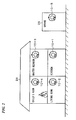
- FIG. 9 is an explanatory drawing that shows the state of the alarm device of the present embodiment installed in a residence.
- alarm devices 110-1 to 110-4 of the present embodiment are installed in the kitchen, living room, master bedroom, and a child's room of a residence 124, and moreover, an alarm device 110-5 is installed in a garage 126 that is built outside.
- the alarm devices 110-1 to 110-5 are each provided with a function to mutually transmit and receive wirelessly an event signal, and the five alarm devices 110-1 to 110-5 constitute one group to perform fire monitoring of the entire residence 124.
- the alarm device 110-4 detects the fire and starts an alarm.
- the detection of the fire and starting of the alarm is called “alarm activation" in the alarm device.
- the alarm device 110-4 activates an alarm
- the alarm device 110-4 functions as the linked source, and transmits wirelessly the event signal that indicates a fire alarm activation to the other alarm devices 110-1 to 110-3 and 110-5 that serve as linked destinations.
- the other alarm devices 110-1 to 110-3 and 110-5 receive the event signal that indicates fire alarm activation from the alarm device 110-4 that is the linked source, they perform an alarm operation as linked destinations.
- the voice message "Woo Woo...The fire alarm has been activated. Please confirm" is output continuously.
- the voice message "Woo Woo...Another fire alarm has been activated. Please confirm” is output continuously.
- the alarm stop switch 120 that is provided on the alarm device shown in FIG. 8A is operated, the stop process of the alarm sound is performed.
- the alarm devices 10-1 to 10-5 are provided with a low battery monitoring function that monitors the running down of the battery, and when it detects a low battery, for example, it intermittently outputs a "beep" alarm sound at a predetermined time interval, and reports that a failure has occurred.
- the failure source alarm device that detected a low battery wirelessly transmits an event signal that indicates the occurrence of a low battery to the other alarm devices, and the same low battery alarm is output at the other alarm devices as well. As a result, when a low battery is detected in any alarm device, a failure alarm is output from all of the alarm devices that constitute the group that performs linked alarms.
- the normal discontinuous reception cycle T12 of the reception circuit 144 is changed to a longer discontinuous reception cycle T14 to lower the consumption current, and prolong the battery life.
- the normal transmission time T3 of the transmission circuit 142 is changed to a longer transmission time T5.
- the alarm devices 110-1 to 110-5 monitor for a sensor failure besides a low battery, and when they detect a sensor failure, perform a linked alarm in the same manner as the low battery detection.
- FIG. 10 is a block diagram that shows the alarm device of the present embodiment.
- FIG. 10 shows in detail the circuit configuration of the alarm device 110-1, among the five alarm devices 110-1 to 110-5 shown in FIG. 9 .
- the alarm device 110-1 is provided with a CPU 128. Also, corresponding to this CPU 128, it is further provided with a wireless circuit section 130 that is provided with an antenna 131, a storage circuit section 132, a sensor section 134, an alert section 136, an operating section 138, and a battery power supply 140.
- the wireless circuit section 130 is provided with a transmission circuit 142 and a reception circuit 144, and is designed to be capable of wirelessly transmitting and receiving event signals to/from the other alarm devices 110-2 to 110-5.
- As the wireless circuit section 130 in Japan it is preferable to adopt a constitution based on for example STD-30, which is known as the standard for specified low-power radio stations in the 400 MHz band (ARIB Standard for Radio Equipment for Radio Station of Low Power Security System), or STD-T67 (ARIB Standard for Telemeter, Telecontrol and Data Transmission Radio Equipment for Specified Low Power Radio Stations).
- the wireless circuit section 130 for places outside of Japan, it is preferable to adopt a constitution that is based on the standard for allocated radio stations of that region.
- the reception circuit 144 performs a discontinuous reception operation.
- the discontinuous reception cycle T12 of the reception circuit 144 is a cycle that is determined at the design stage of the alarm device, so as to lead to average current consumption that ensures a battery life of for example 10 years, and is the default cycle that is set at the shipping stage.
- the reception circuit 144 of the present embodiment is designed to be capable of changing the default discontinuous reception cycle T12 that is set in advance to a long discontinuous reception cycle T13 in order to extend battery life.
- the transmission time of the transmission circuit 142 of the alarm devices that have not detected a low battery is changed from the normal transmission time T3 to a longer transmission time T5.
- a memory 146 is provided in the storage circuit section 132.
- a transmission source code 150 that serves as an ID (identifier) that specifies the alarm device, and a group code 152 for constituting a group that performs a linked alarm with a plurality of alarms as shown in FIG. 9 is housed in the memory 146.
- the transmission source code 150 the number of alarm devices to be provided domestically is calculated, and for example a code of 26 bits is used so that the same code does not overlap.
- the group code 152 is a code that is set so as to be common for the plurality of alarm devices that constitute a group, and when the group code that is included in the event signal from another alarm device that is received by the wireless circuit section 130 matches the group code 152 that is registered in the memory 146, that event signal is received as a valid signal and processed.
- the memory 146 is used in the storage circuit section 132, but a DIP switch may be provided instead of the memory 146, so that the transmission source code 150 and the group code 152 may be set by this DIP switch.
- the storage circuit section 132 that uses a DIP switch is preferred.
- the smoke detector section 116 is provided in the sensor section 134, and outputs a smoke detection signal corresponding to the smoke density to the CPU 128. Besides the smoke detector section 116, a thermistor that detects the temperature from a fire may be provided. Also, in the case of an alarm device for detecting gas leaks, a gas leak sensor is provided in the sensor section 134.
- the speaker 156 and the LED 122 are provided in the alert section 136.
- the speaker 156 outputs a voice message from a speech synthesis circuit section that is not illustrated or an alarm sound.
- the LED 122 by blinking and flashing, or turning on, indicates an anomaly such as a fire or a failure.
- the alarm stop switch 120 and a transmission and reception time control section 62 are provided in the operating section 138.
- the alarm stop switch 120 When the alarm stop switch 120 is operated, it is possible to stop the alarm sound that is sounding from the alarm device 110-1.
- the alarm stop switch 120 also doubles as a check switch in the present embodiment.
- the alarm stop switch 120 is in effect when the alert section 136 is outputting an alarm sound from the speaker 156.
- the alarm stop switch 120 functions as a check switch, and when the check switch is pushed, a voice message for inspection is output from the alert section 136.
- the battery power supply 140 uses for example alkaline dry cells of a predetermined number, and regarding the battery capacity, a battery service life of about 10 years is ensured due to the reduced power consumption of the entire circuit section including the wireless circuit section 130 in the alarm device 110-1.
- an anomaly monitoring section 158 In the CPU 128, an anomaly monitoring section 158, a low battery monitoring section 160 and the transmission and reception time control section 162 are provided as functions that are realized by the execution of programs.
- the anomaly monitoring section 158 causes the repeated output of an alarm sound indicating the linked source from the speaker 156 of the alert section 136, for example, "Woo Woo...The fire alarm has been activated. Please confirm", and causes the transmission of an event signal that indicates fire alarm activation from the antenna 31 to the other alarm devices 110-2 to 110-5 by the transmission circuit 142 of the wireless circuit section 130.
- the anomaly monitoring section 158 causes an alarm sound indicating the linked destination, for example, the voice message "Woo Woo...Another fire alarm has been activated. Please confirm" to be output continuously from the speaker 156 of the alert section 136.
- the LED 122 of the alert section 136 is made to blink, for example.
- the LED 122 of the alert section 136 is made to flash.
- either of the linked source alarm and the linked destination alarm may be a blinking or flashing display of the same LED 122.
- the low battery monitoring section 160 When the low battery monitoring section 160 has detected a low battery due to a voltage drop of the battery power supply 140, it emits a short low battery alarm sound such as a "beep" once every minute, for example, and transmits an event signal that indicates a low battery to the other alarm devices 110-2 to 110-5.
- a short low battery alarm sound such as a "beep" once every minute, for example
- the low battery monitoring section 160 detects a low battery.
- the low battery monitoring section 160 performs linked output of the failure alarm sound. Warning of a low battery to the linked destinations may consist of causing the LED 122 to blink in synchronization with the alarm sound.
- the transmission and reception time control section 162 changes the discontinuous reception cycle T12 of the reception circuit 44 that has been initially set to a longer cycle T13 to extend the battery life, and on the other hand when an event signal denoting a low battery has been received from another alarm device, it changes the transmission time T3 of the transmission circuit 142 that has been initially set to a transmission time T5 that is at least the changed discontinuous reception cycle T13.
- FIG. 11 is an explanatory drawing that shows the format of the event signal used in the present embodiment.
- an event signal 148 is constituted by the transmission source code 150, the group code 152, and the event code 154.
- the transmission source code 150 is for example a code of 26 bits.
- the group code 152 is for example a code of 8 bits, and the same group code is set for the five alarm devices 110-1 to 110-5 of FIG. 10 , for example, that constitute the same group.
- the group code 152 in addition to setting the same group code for each alarm device of the same group, it may be a group code differing for each alarm device that is found from arithmetic of a reference code that is common to each alarm device that constitutes a group that is defined in advance, and a transmission source code that is unique to each alarm device.
- the event code 154 is a code that expresses the event content of an anomaly such as a fire or gas leak or a failure.
- a three-bit code is used, with for example "001" denoting a fire, "010” denoting a gas leak, "011” denoting a failure, and the remainder serving as a reserve.
- FIG. 12 is a time chart that shows the normal operation on the transmission side and the reception side in the present embodiment.
- (A) shows the transmission operation of the transmission side alarm device
- (B) shows the reception operation of the reception side alarm device
- (C) shows the alarm output operation of the reception side alarm device.
- an event signal that indicates the fire alarm activation is transmitted as shown in (A) of FIG. 12 .
- the transmission time T3 of the fire alarm activation event signal is made to be at least the discontinuous reception cycle T12.
- FIG. 13 is a time chart that shows the operation on the transmission side and the reception side during low battery detection in the present embodiment.
- (A) shows the transmission operation of the transmission side alarm device
- (B) shows the reception operation of the reception side alarm device
- (C) shows the alarm output operation of the reception side alarm device.
- T1 5 seconds
- T3 20 seconds.
- FIG. 14 is a time chart that shows the relationship between the discontinuous reception cycle and the average consumption current in the present embodiment.
- discontinuous reception cycle T12 being changed to the longer discontinuous reception cycle T14 when a low battery is detected, even if the battery power supply 140 is in a low battery state, it is possible to reduce the consumption current of the reception circuit 144, and thus to extend as much as possible the battery life.
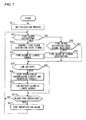
- FIG. 15 is a flowchart that shows the process by the CPU 128 that is provided in the alarm device 110-1 of FIG. 10 .
- Step S101 an initialization process is performed.
- this initialization process is included a process of setting a linked group with the alarm devices 110-1 to 110-5.
- Step S102 the alarm device enters the monitoring state, and in Step S102, the presence of a fire alarm activation by the smoke detector section 116 that is provided in the sensor section 132 is determined.
- Step S103 the process proceeds to Step S103, and after transmitting the fire alarm activation event signal to the other alarm devices 110-2 to 110-5, in Step S104 the fire alarm of the linked source is acoustically output from the speaker 156 of the alert section 136 and the LED 122 is controlled to turn on.
- Step S102 the process proceeds to Step S105, in which it is determined whether or not a fire alarm activation event signal has been received from another alarm device, and when the reception of a fire alarm activation event signal is determined, a fire alarm of the linked destination is output in Step S106.
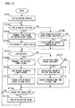
- Step S107 the presence of a low battery detection is determined, and if low battery detection is determined, the process proceeds to Step S108, and after transmitting an event signal that shows a low battery to the other alarm devices 110-2 to 110-5, a discontinuous linked source low battery alarm is output in Step S109.
- Step S 110 the discontinuous cycle of the reception circuit 144 is changed from the initially set cycle T12 to, for example, a cycle T14 that is double.
- Step S111 the presence of the reception of an event signal that shows a low battery from the other alarm devices 110-1 1 to 110-5 is determined in Step S111.
- Step S 112. a discontinuous linked destination low battery alarm is output in Step S 112.
- the reception operation time of the reception circuit 144 is changed from the normal T3 time to the longer T5 time.
- Step S 114 when the alarm stop operation during an alarm is determined, the alarm sound is stopped in Step S 115.
- the aforementioned embodiment is one that takes as an example an alarm device that is intended for fire detection, but it is possible to apply as is the monitoring process that includes the preliminary anomaly of the present embodiment for an alarm device that detects other anomalies, such as an alarm device for gas leaks or an alarm device for crime prevention. Also, it is not limited to residences, and can be also applied to alarm devices catering to various uses such as for buildings and offices.
- the aforementioned embodiment is one that takes as an example the case of integrally providing the sensor section in the alarm device, but as another embodiment it may also be an alarm device in which the sensor section is provided separately from the alarm device.
- the present invention is not limited to only the aforementioned embodiments, and includes suitable modifications that do not impair the objects and advantages thereof, and furthermore is not subject to limitations by only the numerical values shown in the aforementioned embodiments.
- the alarm device of the present invention it is possible to increase reliability by extending as much as possible the remaining time until a battery runs down even if a low battery alarm has been emitted.
Landscapes
- Physics & Mathematics (AREA)
- General Physics & Mathematics (AREA)
- Business, Economics & Management (AREA)
- Emergency Management (AREA)
- Engineering & Computer Science (AREA)
- Computer Security & Cryptography (AREA)
- Alarm Systems (AREA)
- Fire Alarms (AREA)
Claims (2)
- Alarmvorrichtung (110 - 1 bis 110 - 5), umfassend:eine Batteriestromversorgung (140),einen Sensorabschnitt (116), der ein Anomalie-Feststellsignal ausgibt für den Fall, dass eine Anomalie festgestellt wird,einen Alarmabschnitt (136), der einen ersten Alarm, basierend auf dem Anomalie-Feststellsignal, ausgibt,einen Empfangsschaltungs-Abschnitt (144), der intermittierend ein Ereignissignal von einer anderen Alarmvorrichtung empfängt, der als eine verbundene Gruppe der Alarmvorrichtung an jedem vorbestimmten Empfangszyklus eingestellt ist, wobei der Empfangszyklus eine Empfangsbetriebszeit (T1) und eine Ruhezeit umfasst,einen Übertragungsschaltungs-Abschnitt (142), der ununterbrochen ein Ereignissignal an die andere Alarmvorrichtung während einer Übertragungszeit überträgt, die mindestens der vorbestimmte Empfangszyklus ist;einen Anomalieanzeige-Abschnitt (158), der, wenn der Sensorabschnitt eine Anomalie festgestellt hat, verursacht, dass der Alarmabschnitt den ersten Anomaliealarm basierend auf dem Anomalie-Feststellsignal ausgibt und die Übertragung eines Ereignissignals, das der Anomalie der Alarmvorrichtung zugeordnet ist, an die andere Alarmvorrichtung durch den Übertragungsschaltungs-Abschnitt hervorruft, und andererseits, wenn der Empfangsschaltungs-Abschnitt von der anderen Alarmvorrichtung ein Ereignissignal empfangen hat, das einer Anomalie der anderen Alarmvorrichtung zugeordnet ist, verursacht, dass der Alarmabschnitt einen zweiten Anomaliealarm ausgibt,einen Batterieentladungs-Überwachungsabschnitt (160), der die Ausgabe eines Batterieentladungs-Alarms aus dem Alarmabschnitt verursacht, der einen Spannungsabfall der Alarmvorrichtung und der anderen Alarmvorrichtung ankündigt; undeinen Übertragungs- und Empfangszeit-Steuerabschnitt (162), der die Übertragungszeit des Übertragungsschaltungs-Abschnitts und den vorbestimmten Empfangszyklus des Empfangsschaltungs-Abschnitts steuert,wobei das Ereignissignal einen Übertragungs-Herkunftscode, der die Alarmvorrichtung spezifiziert, einen Gruppencode, der gemeinsam für eine Vielzahl von Alarmvorrichtungen ist, die eine Gruppe bilden, und ein Ereigniscode umfasst, der einen Ereignisinhalt einer Anomalie ausdrückt; undwenn ein Spannungsabfall der Batteriestromversorgung festgestellt wird, der Batterieentladungs-Überwachungsabschnitt (160) verursacht, dass der Alarmabschnitt einen Batterieentladungs-Alarm der Alarmvorrichtung ausgibt und verursacht, dass der Übertragungsschaltungs-Abschnitt ein Ereignissignal, das dem Spannungsabfall der Alarmvorrichtung zugeordnet ist, an die andere Alarmvorrichtung überträgt, dadurch gekennzeichnet, dass:wenn der Spannungsabfall der Batteriestromversorgung festgestellt wird, der Übertragungs- und Empfangszeit-Steuerabschnitt (162) den vorbestimmten Empfangszyklus (T12) des Empfangsschaltungs-Abschnitts zu einem langen Empfangszyklus (T13, T14) ändert, wobei im langen Empfangszyklus die Empfangsbetriebszeit (T1) unverändert bleibt und die Ruhezeit ausgedehnt wird; undwenn ein Ereignissignal, das einem Spannungsabfall der anderen Alarmvorrichtung zugeordnet ist, von der anderen Alarmvorrichtung empfangen wird, der Batterieentladungs-Überwachungsabschnitt (160) verursacht, dass der Alarmabschnitt einen Batterieentladungs-Alarm der anderen Alarmvorrichtung ausgibt und der Übertragungs- und Empfangszeit-Steuerabschnitt die Übertragungszeit des Übertragungsschaltungs-Abschnitts auf eine Zeit (T5) ändert, die gleich oder größer als der lange Empfangszyklus, basierend auf dem Ereignissignal der anderen Alarmvorrichtung, ist.
- Alarmvorrichtung nach Anspruch 1, wobei der Batterieentladungs-Überwachungsabschnitt (60, 160) den Spannungsabfall feststellt, wenn die Batteriespannung auf eine Grenzspannung abgefallen ist, bei der die normale Funktion der Alarmvorrichtung über einer vorbestimmten verbleibenden Zeit gehalten werden kann.
Priority Applications (1)
| Application Number | Priority Date | Filing Date | Title |
|---|---|---|---|
| EP13164058.3A EP2618318A3 (de) | 2008-04-28 | 2009-03-17 | Alarmvorrichtung |
Applications Claiming Priority (3)
| Application Number | Priority Date | Filing Date | Title |
|---|---|---|---|
| JP2008002728U JP3143140U (ja) | 2008-04-28 | 2008-04-28 | 警報器 |
| JP2008002727U JP3143139U (ja) | 2008-04-28 | 2008-04-28 | 警報器 |
| PCT/JP2009/055194 WO2009133726A1 (ja) | 2008-04-28 | 2009-03-17 | 警報器 |
Related Child Applications (1)
| Application Number | Title | Priority Date | Filing Date |
|---|---|---|---|
| EP13164058.3 Division-Into | 2013-04-17 |
Publications (3)
| Publication Number | Publication Date |
|---|---|
| EP2284815A1 EP2284815A1 (de) | 2011-02-16 |
| EP2284815A4 EP2284815A4 (de) | 2011-05-04 |
| EP2284815B1 true EP2284815B1 (de) | 2013-06-19 |
Family
ID=41254949
Family Applications (2)
| Application Number | Title | Priority Date | Filing Date |
|---|---|---|---|
| EP09738663.5A Active EP2284815B1 (de) | 2008-04-28 | 2009-03-17 | Alarmvorrichtung |
| EP13164058.3A Ceased EP2618318A3 (de) | 2008-04-28 | 2009-03-17 | Alarmvorrichtung |
Family Applications After (1)
| Application Number | Title | Priority Date | Filing Date |
|---|---|---|---|
| EP13164058.3A Ceased EP2618318A3 (de) | 2008-04-28 | 2009-03-17 | Alarmvorrichtung |
Country Status (6)
| Country | Link |
|---|---|
| US (1) | US8514091B2 (de) |
| EP (2) | EP2284815B1 (de) |
| KR (1) | KR20110004395A (de) |
| CN (1) | CN102016942A (de) |
| AU (1) | AU2009241098B2 (de) |
| WO (1) | WO2009133726A1 (de) |
Families Citing this family (11)
| Publication number | Priority date | Publication date | Assignee | Title |
|---|---|---|---|---|
| US8310366B2 (en) * | 2008-12-18 | 2012-11-13 | Symbol Technologies, Inc. | RFID device and related method for providing assistance for locating it |
| JP4944229B2 (ja) * | 2010-07-22 | 2012-05-30 | ホーチキ株式会社 | 警報器 |
| JP5792645B2 (ja) | 2012-01-13 | 2015-10-14 | ルネサスエレクトロニクス株式会社 | 半導体装置およびその制御方法 |
| JP6089841B2 (ja) * | 2013-03-21 | 2017-03-08 | 株式会社デンソー | 車載緊急通報装置 |
| JP6427772B2 (ja) | 2013-12-26 | 2018-11-28 | オプテックス株式会社 | 電池駆動式の防犯用センサ装置 |
| US10057850B2 (en) * | 2014-03-24 | 2018-08-21 | Acer Incorporated | Methods for deferring communications between a mobile communication device and a service network |
| CN104851222B (zh) * | 2015-05-28 | 2017-07-18 | 深圳市欣横纵数码科技有限公司 | 一种nvsg涉核单位综合安保管理系统的管理方法 |
| CN106600908A (zh) * | 2017-01-24 | 2017-04-26 | 江苏友穗传感科技股份有限公司 | 一种电池驱动低功耗燃气泄漏报警装置 |
| JP2019207526A (ja) * | 2018-05-29 | 2019-12-05 | パナソニックIpマネジメント株式会社 | 異常警報器 |
| EP3921915A1 (de) * | 2019-02-06 | 2021-12-15 | British Telecommunications public limited company | Netzwerkvorrichtungsverwaltung |
| CN112017410A (zh) * | 2019-05-28 | 2020-12-01 | 瑞昱半导体股份有限公司 | 事件警报器和事件警报系统 |
Citations (2)
| Publication number | Priority date | Publication date | Assignee | Title |
|---|---|---|---|---|
| JPH03201196A (ja) * | 1989-12-28 | 1991-09-03 | Hochiki Corp | 無線式警報システム |
| JPH1155176A (ja) * | 1997-08-08 | 1999-02-26 | Mitsubishi Electric Corp | 無線通信端末器 |
Family Cites Families (15)
| Publication number | Priority date | Publication date | Assignee | Title |
|---|---|---|---|---|
| JP2857196B2 (ja) | 1990-01-25 | 1999-02-10 | 松下電器産業株式会社 | ワイヤレスモニタ装置 |
| JP2773375B2 (ja) * | 1990-04-04 | 1998-07-09 | 松下電器産業株式会社 | 送信装置並びに受信装置および送受信装置 |
| US5587705A (en) * | 1994-08-29 | 1996-12-24 | Morris; Gary J. | Multiple alert smoke detector |
| EP1119837B1 (de) * | 1998-10-06 | 2004-02-11 | Interlogix, Inc. | Drahtloses hausfeuer - und sicherheitswarnungssystem |
| DE10138229B4 (de) * | 2001-08-03 | 2009-10-01 | Siemens Gebäudesicherheit GmbH & Co. oHG | Verfahren zur Funkübertragung in einem Gefahrenmeldesystem |
| US20070149139A1 (en) * | 2004-06-10 | 2007-06-28 | Jean-Louis Gauvreau | Wireless Network System with Energy Management |
| DE602005027374D1 (de) * | 2004-10-18 | 2011-05-19 | Kidde Portable Equipment Inc | Frequenzkommunikationsschema in lebenserhaltenden vorrichtungen |
| JP2006270505A (ja) * | 2005-03-24 | 2006-10-05 | Nohmi Bosai Ltd | 伝送システムの信号伝送方式 |
| JP4584778B2 (ja) * | 2005-06-13 | 2010-11-24 | ホーチキ株式会社 | 警報器 |
| JP4865263B2 (ja) | 2005-07-01 | 2012-02-01 | ホーチキ株式会社 | 火災警報器 |
| JP2007094719A (ja) | 2005-09-28 | 2007-04-12 | Yazaki Corp | 無線装置 |
| JP4736970B2 (ja) | 2006-06-21 | 2011-07-27 | パナソニック株式会社 | 空気調和装置 |
| JP2008002728A (ja) | 2006-06-21 | 2008-01-10 | Matsushita Electric Ind Co Ltd | 冷蔵庫 |
| US7554439B2 (en) * | 2006-10-11 | 2009-06-30 | Lookout Portable Security | Remote monitor system with radio dispatch |
| GB2443021A (en) | 2006-10-18 | 2008-04-23 | Ian Hinds | Monitoring System using Multi-Hop Mesh Networks |
-
2009
- 2009-03-17 AU AU2009241098A patent/AU2009241098B2/en not_active Ceased
- 2009-03-17 EP EP09738663.5A patent/EP2284815B1/de active Active
- 2009-03-17 CN CN2009801140124A patent/CN102016942A/zh active Pending
- 2009-03-17 EP EP13164058.3A patent/EP2618318A3/de not_active Ceased
- 2009-03-17 KR KR1020107023823A patent/KR20110004395A/ko not_active Application Discontinuation
- 2009-03-17 WO PCT/JP2009/055194 patent/WO2009133726A1/ja active Application Filing
- 2009-03-17 US US12/936,989 patent/US8514091B2/en active Active
Patent Citations (2)
| Publication number | Priority date | Publication date | Assignee | Title |
|---|---|---|---|---|
| JPH03201196A (ja) * | 1989-12-28 | 1991-09-03 | Hochiki Corp | 無線式警報システム |
| JPH1155176A (ja) * | 1997-08-08 | 1999-02-26 | Mitsubishi Electric Corp | 無線通信端末器 |
Also Published As
| Publication number | Publication date |
|---|---|
| CN102016942A (zh) | 2011-04-13 |
| EP2284815A1 (de) | 2011-02-16 |
| AU2009241098A1 (en) | 2009-11-05 |
| AU2009241098B2 (en) | 2013-08-22 |
| US20110037603A1 (en) | 2011-02-17 |
| KR20110004395A (ko) | 2011-01-13 |
| US8514091B2 (en) | 2013-08-20 |
| WO2009133726A1 (ja) | 2009-11-05 |
| EP2284815A4 (de) | 2011-05-04 |
| EP2618318A3 (de) | 2013-11-13 |
| EP2618318A2 (de) | 2013-07-24 |
Similar Documents
| Publication | Publication Date | Title |
|---|---|---|
| EP2284815B1 (de) | Alarmvorrichtung | |
| US8717150B2 (en) | Alarming device | |
| US8432277B2 (en) | Alarm device and alarm system | |
| US9087444B2 (en) | Alarm device | |
| JP3143139U (ja) | 警報器 | |
| US20110018706A1 (en) | Alarm device and alarm system | |
| JP3143138U (ja) | 警報器 | |
| JP3143140U (ja) | 警報器 | |
| JP5266078B2 (ja) | 警報システム及び警報器 | |
| JP6253951B2 (ja) | 警報器 | |
| JP5781792B2 (ja) | 警報器及び監視システム | |
| JP5507930B2 (ja) | 警報器及び警報システム | |
| EP2284817B1 (de) | Alarm | |
| JP5744577B2 (ja) | 警報器及び監視システム | |
| JP5296032B2 (ja) | 警報器 | |
| JP2011003114A (ja) | 警報器 | |
| JP2010020663A (ja) | 警報器 | |
| JP2010272042A (ja) | 警報器及び警報システム | |
| JP4944229B2 (ja) | 警報器 | |
| AU2013206623B2 (en) | Alarming device | |
| JP2011044172A (ja) | 警報器 | |
| JP5536938B2 (ja) | 警報器 | |
| JP5343143B2 (ja) | 警報器 | |
| JP5893835B2 (ja) | 警報器及び監視システム | |
| JP2011165109A (ja) | 火災警報器 |
Legal Events
| Date | Code | Title | Description |
|---|---|---|---|
| PUAI | Public reference made under article 153(3) epc to a published international application that has entered the european phase |
Free format text: ORIGINAL CODE: 0009012 |
|
| 17P | Request for examination filed |
Effective date: 20101026 |
|
| AK | Designated contracting states |
Kind code of ref document: A1 Designated state(s): AT BE BG CH CY CZ DE DK EE ES FI FR GB GR HR HU IE IS IT LI LT LU LV MC MK MT NL NO PL PT RO SE SI SK TR |
|
| AX | Request for extension of the european patent |
Extension state: AL BA RS |
|
| A4 | Supplementary search report drawn up and despatched |
Effective date: 20110404 |
|
| DAX | Request for extension of the european patent (deleted) | ||
| 17Q | First examination report despatched |
Effective date: 20111209 |
|
| REG | Reference to a national code |
Ref country code: DE Ref legal event code: R079 Ref document number: 602009016543 Country of ref document: DE Free format text: PREVIOUS MAIN CLASS: G08B0017000000 Ipc: G08B0029180000 |
|
| GRAP | Despatch of communication of intention to grant a patent |
Free format text: ORIGINAL CODE: EPIDOSNIGR1 |
|
| RIC1 | Information provided on ipc code assigned before grant |
Ipc: G08B 25/00 20060101ALI20121204BHEP Ipc: G08B 17/00 20060101ALI20121204BHEP Ipc: G08B 29/18 20060101AFI20121204BHEP |
|
| GRAS | Grant fee paid |
Free format text: ORIGINAL CODE: EPIDOSNIGR3 |
|
| GRAA | (expected) grant |
Free format text: ORIGINAL CODE: 0009210 |
|
| AK | Designated contracting states |
Kind code of ref document: B1 Designated state(s): AT BE BG CH CY CZ DE DK EE ES FI FR GB GR HR HU IE IS IT LI LT LU LV MC MK MT NL NO PL PT RO SE SI SK TR |
|
| REG | Reference to a national code |
Ref country code: GB Ref legal event code: FG4D |
|
| REG | Reference to a national code |
Ref country code: CH Ref legal event code: EP |
|
| REG | Reference to a national code |
Ref country code: AT Ref legal event code: REF Ref document number: 618033 Country of ref document: AT Kind code of ref document: T Effective date: 20130715 |
|
| REG | Reference to a national code |
Ref country code: IE Ref legal event code: FG4D |
|
| REG | Reference to a national code |
Ref country code: DE Ref legal event code: R096 Ref document number: 602009016543 Country of ref document: DE Effective date: 20130814 |
|
| PG25 | Lapsed in a contracting state [announced via postgrant information from national office to epo] |
Ref country code: FI Free format text: LAPSE BECAUSE OF FAILURE TO SUBMIT A TRANSLATION OF THE DESCRIPTION OR TO PAY THE FEE WITHIN THE PRESCRIBED TIME-LIMIT Effective date: 20130619 Ref country code: LT Free format text: LAPSE BECAUSE OF FAILURE TO SUBMIT A TRANSLATION OF THE DESCRIPTION OR TO PAY THE FEE WITHIN THE PRESCRIBED TIME-LIMIT Effective date: 20130619 Ref country code: ES Free format text: LAPSE BECAUSE OF FAILURE TO SUBMIT A TRANSLATION OF THE DESCRIPTION OR TO PAY THE FEE WITHIN THE PRESCRIBED TIME-LIMIT Effective date: 20130930 Ref country code: SE Free format text: LAPSE BECAUSE OF FAILURE TO SUBMIT A TRANSLATION OF THE DESCRIPTION OR TO PAY THE FEE WITHIN THE PRESCRIBED TIME-LIMIT Effective date: 20130619 Ref country code: GR Free format text: LAPSE BECAUSE OF FAILURE TO SUBMIT A TRANSLATION OF THE DESCRIPTION OR TO PAY THE FEE WITHIN THE PRESCRIBED TIME-LIMIT Effective date: 20130920 Ref country code: NO Free format text: LAPSE BECAUSE OF FAILURE TO SUBMIT A TRANSLATION OF THE DESCRIPTION OR TO PAY THE FEE WITHIN THE PRESCRIBED TIME-LIMIT Effective date: 20130919 Ref country code: SI Free format text: LAPSE BECAUSE OF FAILURE TO SUBMIT A TRANSLATION OF THE DESCRIPTION OR TO PAY THE FEE WITHIN THE PRESCRIBED TIME-LIMIT Effective date: 20130619 |
|
| REG | Reference to a national code |
Ref country code: AT Ref legal event code: MK05 Ref document number: 618033 Country of ref document: AT Kind code of ref document: T Effective date: 20130619 |
|
| REG | Reference to a national code |
Ref country code: LT Ref legal event code: MG4D |
|
| PG25 | Lapsed in a contracting state [announced via postgrant information from national office to epo] |
Ref country code: HR Free format text: LAPSE BECAUSE OF FAILURE TO SUBMIT A TRANSLATION OF THE DESCRIPTION OR TO PAY THE FEE WITHIN THE PRESCRIBED TIME-LIMIT Effective date: 20130619 Ref country code: BG Free format text: LAPSE BECAUSE OF FAILURE TO SUBMIT A TRANSLATION OF THE DESCRIPTION OR TO PAY THE FEE WITHIN THE PRESCRIBED TIME-LIMIT Effective date: 20130919 |
|
| REG | Reference to a national code |
Ref country code: NL Ref legal event code: VDEP Effective date: 20130619 |
|
| PG25 | Lapsed in a contracting state [announced via postgrant information from national office to epo] |
Ref country code: LV Free format text: LAPSE BECAUSE OF FAILURE TO SUBMIT A TRANSLATION OF THE DESCRIPTION OR TO PAY THE FEE WITHIN THE PRESCRIBED TIME-LIMIT Effective date: 20130619 |
|
| PG25 | Lapsed in a contracting state [announced via postgrant information from national office to epo] |
Ref country code: IS Free format text: LAPSE BECAUSE OF FAILURE TO SUBMIT A TRANSLATION OF THE DESCRIPTION OR TO PAY THE FEE WITHIN THE PRESCRIBED TIME-LIMIT Effective date: 20131019 Ref country code: CY Free format text: LAPSE BECAUSE OF FAILURE TO SUBMIT A TRANSLATION OF THE DESCRIPTION OR TO PAY THE FEE WITHIN THE PRESCRIBED TIME-LIMIT Effective date: 20130918 Ref country code: EE Free format text: LAPSE BECAUSE OF FAILURE TO SUBMIT A TRANSLATION OF THE DESCRIPTION OR TO PAY THE FEE WITHIN THE PRESCRIBED TIME-LIMIT Effective date: 20130619 Ref country code: SK Free format text: LAPSE BECAUSE OF FAILURE TO SUBMIT A TRANSLATION OF THE DESCRIPTION OR TO PAY THE FEE WITHIN THE PRESCRIBED TIME-LIMIT Effective date: 20130619 Ref country code: PT Free format text: LAPSE BECAUSE OF FAILURE TO SUBMIT A TRANSLATION OF THE DESCRIPTION OR TO PAY THE FEE WITHIN THE PRESCRIBED TIME-LIMIT Effective date: 20131021 Ref country code: AT Free format text: LAPSE BECAUSE OF FAILURE TO SUBMIT A TRANSLATION OF THE DESCRIPTION OR TO PAY THE FEE WITHIN THE PRESCRIBED TIME-LIMIT Effective date: 20130619 Ref country code: CZ Free format text: LAPSE BECAUSE OF FAILURE TO SUBMIT A TRANSLATION OF THE DESCRIPTION OR TO PAY THE FEE WITHIN THE PRESCRIBED TIME-LIMIT Effective date: 20130619 Ref country code: BE Free format text: LAPSE BECAUSE OF FAILURE TO SUBMIT A TRANSLATION OF THE DESCRIPTION OR TO PAY THE FEE WITHIN THE PRESCRIBED TIME-LIMIT Effective date: 20130619 |
|
| PG25 | Lapsed in a contracting state [announced via postgrant information from national office to epo] |
Ref country code: PL Free format text: LAPSE BECAUSE OF FAILURE TO SUBMIT A TRANSLATION OF THE DESCRIPTION OR TO PAY THE FEE WITHIN THE PRESCRIBED TIME-LIMIT Effective date: 20130619 Ref country code: NL Free format text: LAPSE BECAUSE OF FAILURE TO SUBMIT A TRANSLATION OF THE DESCRIPTION OR TO PAY THE FEE WITHIN THE PRESCRIBED TIME-LIMIT Effective date: 20130619 Ref country code: RO Free format text: LAPSE BECAUSE OF FAILURE TO SUBMIT A TRANSLATION OF THE DESCRIPTION OR TO PAY THE FEE WITHIN THE PRESCRIBED TIME-LIMIT Effective date: 20130619 |
|
| PG25 | Lapsed in a contracting state [announced via postgrant information from national office to epo] |
Ref country code: CY Free format text: LAPSE BECAUSE OF FAILURE TO SUBMIT A TRANSLATION OF THE DESCRIPTION OR TO PAY THE FEE WITHIN THE PRESCRIBED TIME-LIMIT Effective date: 20130619 |
|
| PLBE | No opposition filed within time limit |
Free format text: ORIGINAL CODE: 0009261 |
|
| STAA | Information on the status of an ep patent application or granted ep patent |
Free format text: STATUS: NO OPPOSITION FILED WITHIN TIME LIMIT |
|
| PG25 | Lapsed in a contracting state [announced via postgrant information from national office to epo] |
Ref country code: DK Free format text: LAPSE BECAUSE OF FAILURE TO SUBMIT A TRANSLATION OF THE DESCRIPTION OR TO PAY THE FEE WITHIN THE PRESCRIBED TIME-LIMIT Effective date: 20130619 |
|
| 26N | No opposition filed |
Effective date: 20140320 |
|
| PG25 | Lapsed in a contracting state [announced via postgrant information from national office to epo] |
Ref country code: IT Free format text: LAPSE BECAUSE OF FAILURE TO SUBMIT A TRANSLATION OF THE DESCRIPTION OR TO PAY THE FEE WITHIN THE PRESCRIBED TIME-LIMIT Effective date: 20130619 |
|
| REG | Reference to a national code |
Ref country code: DE Ref legal event code: R097 Ref document number: 602009016543 Country of ref document: DE Effective date: 20140320 |
|
| PG25 | Lapsed in a contracting state [announced via postgrant information from national office to epo] |
Ref country code: LU Free format text: LAPSE BECAUSE OF FAILURE TO SUBMIT A TRANSLATION OF THE DESCRIPTION OR TO PAY THE FEE WITHIN THE PRESCRIBED TIME-LIMIT Effective date: 20140317 |
|
| REG | Reference to a national code |
Ref country code: CH Ref legal event code: PL |
|
| REG | Reference to a national code |
Ref country code: FR Ref legal event code: ST Effective date: 20141128 |
|
| REG | Reference to a national code |
Ref country code: IE Ref legal event code: MM4A |
|
| PG25 | Lapsed in a contracting state [announced via postgrant information from national office to epo] |
Ref country code: FR Free format text: LAPSE BECAUSE OF NON-PAYMENT OF DUE FEES Effective date: 20140331 Ref country code: CH Free format text: LAPSE BECAUSE OF NON-PAYMENT OF DUE FEES Effective date: 20140331 Ref country code: LI Free format text: LAPSE BECAUSE OF NON-PAYMENT OF DUE FEES Effective date: 20140331 Ref country code: IE Free format text: LAPSE BECAUSE OF NON-PAYMENT OF DUE FEES Effective date: 20140317 |
|
| PG25 | Lapsed in a contracting state [announced via postgrant information from national office to epo] |
Ref country code: MT Free format text: LAPSE BECAUSE OF FAILURE TO SUBMIT A TRANSLATION OF THE DESCRIPTION OR TO PAY THE FEE WITHIN THE PRESCRIBED TIME-LIMIT Effective date: 20130619 |
|
| PG25 | Lapsed in a contracting state [announced via postgrant information from national office to epo] |
Ref country code: MC Free format text: LAPSE BECAUSE OF FAILURE TO SUBMIT A TRANSLATION OF THE DESCRIPTION OR TO PAY THE FEE WITHIN THE PRESCRIBED TIME-LIMIT Effective date: 20130619 |
|
| PG25 | Lapsed in a contracting state [announced via postgrant information from national office to epo] |
Ref country code: TR Free format text: LAPSE BECAUSE OF FAILURE TO SUBMIT A TRANSLATION OF THE DESCRIPTION OR TO PAY THE FEE WITHIN THE PRESCRIBED TIME-LIMIT Effective date: 20130619 Ref country code: HU Free format text: LAPSE BECAUSE OF FAILURE TO SUBMIT A TRANSLATION OF THE DESCRIPTION OR TO PAY THE FEE WITHIN THE PRESCRIBED TIME-LIMIT; INVALID AB INITIO Effective date: 20090317 |
|
| PG25 | Lapsed in a contracting state [announced via postgrant information from national office to epo] |
Ref country code: MK Free format text: LAPSE BECAUSE OF FAILURE TO SUBMIT A TRANSLATION OF THE DESCRIPTION OR TO PAY THE FEE WITHIN THE PRESCRIBED TIME-LIMIT Effective date: 20130619 |
|
| PGFP | Annual fee paid to national office [announced via postgrant information from national office to epo] |
Ref country code: DE Payment date: 20210302 Year of fee payment: 13 |
|
| REG | Reference to a national code |
Ref country code: DE Ref legal event code: R119 Ref document number: 602009016543 Country of ref document: DE |
|
| PG25 | Lapsed in a contracting state [announced via postgrant information from national office to epo] |
Ref country code: DE Free format text: LAPSE BECAUSE OF NON-PAYMENT OF DUE FEES Effective date: 20221001 |
|
| PGFP | Annual fee paid to national office [announced via postgrant information from national office to epo] |
Ref country code: GB Payment date: 20230202 Year of fee payment: 15 |