EP2284074B1 - Ship - Google Patents
Ship Download PDFInfo
- Publication number
- EP2284074B1 EP2284074B1 EP10189747.8A EP10189747A EP2284074B1 EP 2284074 B1 EP2284074 B1 EP 2284074B1 EP 10189747 A EP10189747 A EP 10189747A EP 2284074 B1 EP2284074 B1 EP 2284074B1
- Authority
- EP
- European Patent Office
- Prior art keywords
- ship
- propeller
- magnus rotors
- magnus
- ship according
- Prior art date
- Legal status (The legal status is an assumption and is not a legal conclusion. Google has not performed a legal analysis and makes no representation as to the accuracy of the status listed.)
- Active
Links
Images


Classifications
-
- B—PERFORMING OPERATIONS; TRANSPORTING
- B63—SHIPS OR OTHER WATERBORNE VESSELS; RELATED EQUIPMENT
- B63H—MARINE PROPULSION OR STEERING
- B63H9/00—Marine propulsion provided directly by wind power
- B63H9/02—Marine propulsion provided directly by wind power using Magnus effect
-
- B—PERFORMING OPERATIONS; TRANSPORTING
- B63—SHIPS OR OTHER WATERBORNE VESSELS; RELATED EQUIPMENT
- B63H—MARINE PROPULSION OR STEERING
- B63H1/00—Propulsive elements directly acting on water
- B63H1/02—Propulsive elements directly acting on water of rotary type
- B63H1/12—Propulsive elements directly acting on water of rotary type with rotation axis substantially in propulsive direction
- B63H1/14—Propellers
- B63H1/26—Blades
-
- B—PERFORMING OPERATIONS; TRANSPORTING
- B63—SHIPS OR OTHER WATERBORNE VESSELS; RELATED EQUIPMENT
- B63H—MARINE PROPULSION OR STEERING
- B63H21/00—Use of propulsion power plant or units on vessels
- B63H21/20—Use of propulsion power plant or units on vessels the vessels being powered by combinations of different types of propulsion units
-
- B—PERFORMING OPERATIONS; TRANSPORTING
- B63—SHIPS OR OTHER WATERBORNE VESSELS; RELATED EQUIPMENT
- B63H—MARINE PROPULSION OR STEERING
- B63H25/00—Steering; Slowing-down otherwise than by use of propulsive elements; Dynamic anchoring, i.e. positioning vessels by means of main or auxiliary propulsive elements
- B63H25/06—Steering by rudders
- B63H25/38—Rudders
-
- Y—GENERAL TAGGING OF NEW TECHNOLOGICAL DEVELOPMENTS; GENERAL TAGGING OF CROSS-SECTIONAL TECHNOLOGIES SPANNING OVER SEVERAL SECTIONS OF THE IPC; TECHNICAL SUBJECTS COVERED BY FORMER USPC CROSS-REFERENCE ART COLLECTIONS [XRACs] AND DIGESTS
- Y02—TECHNOLOGIES OR APPLICATIONS FOR MITIGATION OR ADAPTATION AGAINST CLIMATE CHANGE
- Y02T—CLIMATE CHANGE MITIGATION TECHNOLOGIES RELATED TO TRANSPORTATION
- Y02T70/00—Maritime or waterways transport
- Y02T70/50—Measures to reduce greenhouse gas emissions related to the propulsion system
- Y02T70/5218—Less carbon-intensive fuels, e.g. natural gas, biofuels
- Y02T70/5236—Renewable or hybrid-electric solutions
Definitions
- the present invention relates to a ship.
- US 4,602,584 also shows a ship in which a plurality of Magnus rotors is used to propel the ship. From the DD 243 251 A1 is also a ship with a Magnus rotor and a Flettner rotor known. In the DE 42 20 57 Also shown is a ship with a Magnus rotor. Further reference is made to the following prior art: US 4,398,895 . DE 101 02 740 A1 . US Pat. No. 6,848,382 B1 . DE 24 30 630 . DE 41 01 238 A ,
- the vertical cylinders rotate about their axis and air flowing in from the side then flows around the cylinder preferably in the direction of rotation due to the surface friction. On the front, therefore, the flow velocity is greater and the static pressure less, so that the ship receives a force in the forward direction.
- SISTEMAR CLT PROPELLERS Presentation to The International Propeller Club Port of Genoa, May 13, 2003 shows a propeller with a bent edge bow.
- a ship which has four Magnus rotors.
- Each of the Magnus rotors is assigned an individually controllable electric motor for rotating the Magnus rotor.
- Each electric motor in turn is associated with a converter to control the speed and / or direction of rotation of the electric motor.
- the ship has a propeller with blades, each having a bent and elliptical edge bow.
- the ship has an oar with a Costa bulb, with at least two vanes arranged on the Costa bulb such that a portion of the turbulence generated by the propeller is converted to a propelling force.
- the ship has a first center rudder and at least two second rudders, each offset a predetermined amount from the first center rudder, the two second rudders having a size twice the size of the center rudder.
- Fig. 1 shows a schematic representation of a ship according to a first embodiment.
- the ship has a hull consisting of an underwater area 16 and an overwater area 15. Furthermore, the ship has four Magnus rotors or Flettner rotors 10, which are arranged at the four corners of the fuselage.
- the ship has a arranged in the forecastle deckhouse 40 with a bridge 30.
- the ship has a screw 50 underwater.
- the ship may also include transverse thrusters, preferably one at the stern and one to two transverse thrusters at the bow. Preferably, these transverse thrusters are electrically driven.
- the accommodations, galley, Proviantiki, fairs, etc. are located in the deckhouse 40.
- the deckhouse 40, the bridge 30 and all structures above the weather deck 14 an aerodynamic shape to reduce the wind resistance. This is achieved in particular by substantially avoiding sharp edges and sharp-edged attachments. In order to minimize the wind resistance, as few bodies are provided.
- the bow of the ship is cut sharply over a relatively long distance.
- the underwater hull is designed to be up to a height of approx. 3 m above the construction waterline 13 with regard to hydrodynamic aspects optimized for optimal resistance.
- the hull of the ship is designed not to a maximum load capacity, but to a minimum resistance (aerodynamic and hydrodynamic).
- the superstructures of the ship are aerodynamically designed. This is achieved in particular in that all surfaces are designed as smooth surfaces. Due to the design of the bridge 30 and the deckhouse 40, it is above all intended to avoid wake-up whirls, so that the control of the Magnus rotors can be as undisturbed as possible.
- the bridge 30 with the deckhouse 40 is preferably arranged at the bow of the ship. An arrangement of the structures in the middle of the ship is also possible, but would unnecessarily hinder the loading or unloading of the cargo, because the structures would thus be located just above the middle of the cargo space.
- the propulsion of the ship is optimized for wind propulsion, so that the ship of the present invention is a sailing ship.
- the Magnus rotors are preferably arranged in the region of the corner points of the holds, so that they span a rectangular area. It should be noted, however, that another arrangement is possible.
- the arrangement of the Magnus rotors is based on a thought that a certain rotor area is required to achieve the desired drive power through the Magnus rotors. By dividing this required surface into a total of four Magnus rotors, the dimensions of the individual Magnus rotors are reduced. By this arrangement of Magnus rotors remain the largest possible continuous area free, which is used in particular for loading and unloading of the ship and allows a recording of a ceiling load in the form of multiple container loads.
- the Magnus rotors are designed so that the same power (about 6000 kW) is achieved by their operation as by the propeller. With sufficient wind, the drive of the ship can thus take place completely through the Magnus rotors 10. This is achieved, for example, at a wind speed of 12 to 14 meters per second, so that the propeller or the main drive can be switched off because it is no longer needed for the propulsion of the ship.
- the Magnus rotors and the main drive are thus designed so that the main drive in insufficient wind only has to provide the difference in performance that can not be supplied by the Magnus rotors.
- a control of the drive is thus such that the Magnus rotors 10 generate the maximum power or approximately the maximum power.
- An increase in the power of the Magnus rotors thus leads directly to a saving in fuel, since no additional energy has to be generated for the electric drive by the main drive.
- the saving of fuel thus results without an adaptation between a driven by an internal combustion engine propeller or main drive and the control of the Magnus rotors is needed.
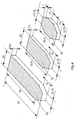
- Fig. 2 shows a side view and a partial sectional view of the ship of Fig. 1 , Here also the Magnus rotors 10, the deckhouse 40 and the bridge 30 are shown.
- the weather deck 14 has light openings 18, which may be covered with transparent material for protection against the weather or seawater.
- the shape of the covers corresponds to that of the other body parts.
- the three loading decks ie a subspace 60, a first intermediate deck 70 and a second intermediate deck 80 are shown.
- Fig. 3 shows another schematic view of the ship of Fig. 1 , Here, in particular, the stern of the ship is shown.
- the ship in turn has an upper portion 15 and a lower portion 16, a deckhouse 40 and a bridge 30 and four Magnus rotors 10.
- the ship has a preferably hydraulically driven rear gate 90, via which rolling stock can be loaded or unloaded into the second intermediate deck 70b.
- the rear gate 90 can have a height of 7 meters and a width of 15 meters.
- a lift can be installed be, so that a rolling loading of the first intermediate deck 80 and the subspace 16 is possible.
- the subspace 16 is located below the construction waterline.
- Fig. 5a shows a sectional view of the holds.
- the subspace 60 is arranged as the lowest loading space.
- the first intermediate deck 70 and the second intermediate deck 80 are arranged above the subspace 60.
- the second intermediate deck 80 is closed by the upper deck 14.
- an operating passage or main deck 85 Provided on the sides of the upper deck is an operating passage or main deck 85, which preferably has openings 18. These openings can optionally be configured closable.
- the cowl hatches of the hatches and the aisle 85 are provided with a cover (the weather deck) along the entire length, so that a surface is formed with a surface which is adapted to the ship's outer skin.
- the pontoons described above are used to divide the interior of the holds, the pontoons can be hung in different holds at a variable height, so that the height of the individual holds can be made variable.
- the cargo space in its course or along its length have different heights, so that in a portion of the hold with a higher height, a corresponding cargo can be accommodated, while in another section of the hold a lower height is present, so that for the overlying cargo space accordingly more height is available.
- a very flexible division of the loading area in the various holds can be achieved.
- ballast tanks are provided, which may be filled with ballast water, for example, to give the ship the required stability.
- ballast tank Above the ballast tank, the main deck 85 is arranged, i. H. the main deck 85 runs outside of the hold next to the hatch 86.
- Fig. 5b shows a further sectional view of the ship from Fig. 1 , Here is a section of the sectional view of Fig. 5a shown.
- the weather deck 14 extends over the main deck 85 and connects to the outer skin of the ship, so that an aerodynamically favorable shape is achieved.
- the main deck 85 has a hatch 86 on the side facing the cargo space. Due to the design of the weather deck or the cover of the main deck, which adjoins the outer skin of the ship, apart from the aerodynamically favorable shape and the main deck 85 is protected from adverse weather conditions.
- the weather deck hatch is closed from back to front, so that the vertical hatch covers between the Magnus rotors on the aft ship with the hatch open.
- a plurality of Laschaugen is provided for the transport of components of a wind turbine.
- the materials for the tank lids of the subspace 60 preferably are not combustible materials, so that lye can be welded in the subspace 60.
- the carrying capacity of the tank ceiling is preferably 17 to 20 tons per square meter. All holds, including the weather deck hatches are preferably also designed for the transport of standard ocean containers. Preferably, five layers of standard sea containers under deck and five layers on deck may be provided to provide a maximum capacity of 824 TEU.
- Fig. 5c shows a sectional view of the deckhouse 40 of the ship of Fig. 1 ,
- the in Fig. 5c Cross-section shown is merely an example.
- the deckhouse is designed round at one end round, while the deckhouse tapers toward the rear streamlined.
- the ship further comprises an on-board crane (not shown), which is preferably provided as a gantry crane with a carrying capacity of, for example, 75 tons.
- the on-board crane is preferably provided on the main deck.
- the rails for the on-board crane preferably run parallel to the hull of the hatches.
- the height of the gantry crane, which extends over the main deck should preferably be designed such that the crane is designed for handling components of wind turbines and is used only secondarily for the handling of containers. Since the crane can be moved along the entire hatch length and along the entire ship's width, any position within the holds can be achieved.
- the boom of the crane is preferably adjustable in height in order to hoist different sized components over the hatch. Its length is therefore preferably 10 meters.
- the gantry crane is designed such that it has a parking position in the front region of the second intermediate deck 70.
- the gantry crane is arranged on a lift platform with rails so that the weather deck can close over it.
- the ship according to the first embodiment preferably has a diesel-electric main drive.
- a diesel-electric main drive Preferably, seven diesel generators, each with 1000 kW electrical power supply the entire electrical system centrally with the main traction motors and the drive motors for the Magnus rotors and the transverse thrusters.
- the diesel units are automatically connected and disconnected according to the requirements of the vehicle electrical system.
- the engine room for the diesel engines is preferably located in the foredeck below the deck superstructures.
- the mounting space has a mounting hatch to the main deck and corresponding devices that allow a partial or complete replacement of aggregates in a port.
- the fuel tanks are preferably located in the forecastle behind the double-skin of the ship.
- the main drive 50 is in this case driven by an electric motor, which in turn receives the electrical power by a diesel-powered generator.
- the main electric traction motor acts directly on a variable pitch propeller, which has a maximum pitch angle of 90 °. The blades can thus be brought into flag position.
- the main traction motor is located behind the lowest cargo compartment with all auxiliary equipment in the main engine room.
- the electrical supply lines between the diesel engine compartment and the main engine room are redundantly implemented both on the port and on the starboard side.
- the ship may have an emergency diesel area in the stern area.
- the rudder of the ship is preferably formed by a hydraulically powered levitation plow to ensure good maneuverability.
- the propeller drive is basically provided to the four Magnus rotors 10.
- the drive and the control of the four Magnus rotors are completely automatic and each independent for each of the Magnus rotors, so that the Magnus rotors also different, d. H. can be controlled in the direction of rotation and speed.
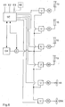
- Fig. 6 shows a block diagram of the control of the ship according to the first embodiment of Fig. 1 ,
- Each of the four Magnus rotors 10 has its own motor M and a separate inverter U.
- the inverters U are connected to a central control unit SE.
- a diesel engine DA is connected to a generator G to generate electrical energy.
- the respective inverters U are connected to the generator G.
- a main drive HA is shown, which is also connected to an electric motor M, which in turn is connected to a separate frequency converter U with both the control unit SE and with the generator G.
- the four Magnus rotors 10 can be controlled both individually and independently of each other.
- the control of the Magnusrotoren and the main drive is done by the control unit SE, which from the current wind measurements (wind speed, wind direction) E1, E2 and based on the information about target and actual speed E3 (and optionally based on navigation information from a navigation unit NE) corresponding speed and direction of rotation for each Magnus rotor 10 and the main drive determined to achieve a maximum propulsive force.
- the control unit SE regulates depending on the thrust of the four Magnus rotors and the current ship speed and the setpoint speed, the main propulsion system steplessly down, as required. So can the wind energy output can be converted directly and automatically into fuel economy. Due to the independent control of the Magnus rotors 10, the ship can be controlled without main drive. In particular, by appropriate control of the respective Magnus rotors 10 stabilization of the ship can be achieved in a strong sea state.
- one or more transverse thrusters QSA may be provided to enhance the maneuverability of the ship.
- a transverse thruster rear and one to two transverse thrusters are provided on the front of the ship.
- Each transverse thruster QSA is assigned a drive motor and an inverter.
- the inverter U is in turn connected to the central control unit SE and the generator G.
- the transverse thrusters (only one is in the Fig. 6 also shown) may be used to control the vessel since they are connected to the central control unit (via the inverter).
- the transverse thrusters QSA can each be individually controlled in terms of their speed and direction of rotation of the central control unit SE. The control can be carried out as described above.
- a variable pitch propeller is usually adjustable in a range of -20 ° to + 20 °. With a setting of + 20 °, a maximum propulsion is generated, while a setting of the variable pitch propeller to -20 ° causes a reverse drive.
- the adjustment range of the variable pitch propeller is designed from -20 ° to + 100 °.
- the propeller can be rotated at about + 90 ° in a flag position, whereby the resistance of the propeller is minimal in pure Magnus drive of the ship.
- This is particularly advantageous in that the ship is made aerodynamic, and it allows earlier shutdown of the propeller, since the Magnus drive earlier can provide the required for the forward travel of the ship performance, since the resistance of the propeller blades must not be overcome.
- the favorable values for the Magnus drive are achieved, for example, in the case of onflows in a range from 30 ° to about 130 °, preferably from 45 ° to 130 °, relative to the ship's course. Since the drive of the ship should be as far as possible by the Magnus rotors, a drive against the wind is limited possible, so that during navigation a certain deviation from the ideal course is possible, thereby better utilization of the drive by the Magnus rotors to enable. Thus, both have the wind direction as well as the wind speed influence the navigation or the steering of the ship.
- the Magnus rotors 10 preferably have a total height of 27 meters above the main deck and a diameter of 3.5 meters. This results in a maximum clearance of 40 meters with a draft of 5 meters. Other dimensions are also possible.
- the electric motors and the inverters of the respective Magnus rotors are located below the rotor in a separate room below deck. Thus, the inverters and the motors are accessible for maintenance purposes.
- the ship may have a towing kite connected to the ship by a pull rope.
- a towing kite can also be used as an auxiliary drive in suitable wind directions in order to continue to save fuel.
- Magnus rotors may have a high speed number of 15 and more, preferably more than 20. Such a high speed number can enable a significant increase in efficiency.
- Fig. 7 shows a modified embodiment of the electric power generating system of the ship.
- the generation system according to Fig. 7 can be in the controller according to Fig. 6 to get integrated.
- two diesel engines or internal combustion engines DA with downstream electric generators G1, G2 are shown.
- the exhaust gases of the diesel engines DA are discharged in an exhaust pipe 110 and fed to a post-combustion unit NV.
- NV post-combustion unit
- the diesel engines DA are claimed correspondingly lower and their fuel consumption is correspondingly lower.
- the thus aftertreated exhaust gases can then be discharged via a chimney 112.
- the electrical energy generated by the generators G1-G3 may be as in Fig. 6 shown are supplied to the motor M of the main drive HA, for example via an electrical board network.
- the converter U and the electric motors M of the Magnus rotors 10 can be supplied with electrical energy via the onboard network.
- the on-board network can also be used to ensure the electrical power supply of the ship.
- Fig. 10a shows very simplified one of the propeller blades 50a with an attached edge bow 55 in the view from behind.
- Fig. 10b is this propeller blade 50a shown in a side view and the kinking to one side edge bow 55 (in the figure to the right) is clearly visible.
- Fig. 10d and 10e show a similar albeit alternative embodiment.
- Fig. 10d It will be appreciated that there are two edge arches 55a, 55b which are angled away from opposite sides of the plane of the propeller blade 50a, as opposed to the illustration in FIGS Fig. 10b, 10c , in which only an edge bow was shown, here two edge arches are provided. As a result, the losses are further reduced by the separation of the flow of the propeller blades 50a and thus provided even more power for the propulsion of the ship.
Description
Die vorliegende Erfindung betrifft ein Schiff.The present invention relates to a ship.
Ein derartiges Schiff ist bereits aus "
Der Magnus-Effekt beschreibt ein Auftreten einer Querkraft, d. h. senkrecht zur Achse und zur Anströmrichtung, bei einem Zylinder, der um seine Achse rotiert und der senkrecht zur Achse angeströmt wird. Die Strömung um den rotierenden Zylinder lässt sich als eine Überlagerung einer homogenen Strömung und eines Wirbels um den Körper auffassen. Durch die ungleichmäßige Verteilung der Gesamtströmung ergibt sich eine unsymmetrische Druckverteilung am Zylinderumfang. Ein Schiff wird somit mit rotierenden bzw. drehenden Rotoren versehen, welche in der Windströmung eine zur wirksamen, d. h. mit der Höchstgeschwindigkeit korrigierten Windrichtung, senkrechte Kraft erzeugen, welche ähnlich wie beim Segeln zum Vortrieb des Schiffes verwendet werden kann. Die senkrecht stehenden Zylinder rotieren um ihre Achse und von der Seite anströmende Luft fließt dann aufgrund der Oberflächenreibung bevorzugt in Drehrichtung um den Zylinder. Auf der Vorderseite ist deshalb die Strömungsgeschwindigkeit größer und der statische Druck geringer, so dass das Schiff eine Kraft in Vorwärtsrichtung erhält.The Magnus effect describes an occurrence of a transverse force, ie perpendicular to the axis and to the direction of flow, in the case of a cylinder which rotates about its axis and which is perpendicular to the axis. The flow around the rotating cylinder can be understood as a superposition of a homogeneous flow and a vortex around the body. Due to the uneven distribution of the total flow results in an asymmetrical pressure distribution at the cylinder circumference. A ship is thus provided with rotating or rotating rotors, which in the wind flow to the effective, ie with the maximum speed corrected wind direction, generate vertical force, which can be used for propulsion of the ship similar to sailing. The vertical cylinders rotate about their axis and air flowing in from the side then flows around the cylinder preferably in the direction of rotation due to the surface friction. On the front, therefore, the flow velocity is greater and the static pressure less, so that the ship receives a force in the forward direction.
""
""
Es ist Aufgabe der vorliegenden Erfindung, ein Schiff vorzusehen, welches einen geringen Kraftstoffverbrauch aufweist.It is an object of the present invention to provide a ship which has a low fuel consumption.
Diese Aufgabe wird durch ein Schiff gemäß Anspruch 1 gelöst.This object is achieved by a ship according to
Es wird darüber hinaus ein Schiff vorgesehen, welches vier Magnus-Rotoren aufweist. Jedem der Magnus-Rotoren ist ein individuell ansteuerbarer elektrischer Motor zum Drehen des Magnus-Rotors zugeordnet. Jedem elektrischen Motor wiederum ist ein Umrichter zugeordnet, um die Drehzahl und/oder die Drehrichtung des elektrischen Motors zu steuern. Das Schiff weist einen Propeller mit Schaufeln auf, die jeweils einen abgeknickten und elliptischen Randbogen aufweisen. Das Schiff weist ein Ruder mit einer Costa-Birne auf, wobei mindestens zwei Leitschaufeln derart an der Costa-Birne angeordnet sind, dass ein Teil der von dem Propeller erzeugten Verwirbelung in eine Vortriebskraft umgewandelt wird. Das Schiff weist einem ersten mittleren Ruder und mindestens zwei zweiten Rudern auf, welche jeweils ein vorgegebenes Maß von dem ersten mittleren Ruder versetzt angeordnet sind, wobei die beiden zweiten Ruder eine Größe aufweisen, welche doppelt so groß wie die Größe des mittleren Ruders ist. In addition, a ship is provided which has four Magnus rotors. Each of the Magnus rotors is assigned an individually controllable electric motor for rotating the Magnus rotor. Each electric motor in turn is associated with a converter to control the speed and / or direction of rotation of the electric motor. The ship has a propeller with blades, each having a bent and elliptical edge bow. The ship has an oar with a Costa bulb, with at least two vanes arranged on the Costa bulb such that a portion of the turbulence generated by the propeller is converted to a propelling force. The ship has a first center rudder and at least two second rudders, each offset a predetermined amount from the first center rudder, the two second rudders having a size twice the size of the center rudder.
Daher wird ein Schiff vorgesehen, welches den Magnus-Effekt zum Antrieb verwenden kann. Durch eine individuelle Ansteuerung der verschiedenen Magnus-Rotoren kann der durch die Magnus-Rotoren resultierende Vortrieb optimiert werden.Therefore, a ship is provided which can use the Magnus effect for propulsion. By individually controlling the various Magnus rotors, the propulsion resulting from the Magnus rotors can be optimized.
Nachfolgend werden die Ausführungsbeispiele und Vorteile der vorliegenden Erfindung unter Bezugnahme auf die beigefügten Zeichnungen näher erläutert.
- Fig. 1
- zeigt eine perspektivische Ansicht eines Schiffes gemäß einem ersten Ausführungsbeispiel,
- Fig. 2
- zeigt eine Seitenansicht und eine teilsweise Schnittansicht des Schiffes von
Fig. 1 , - Fig: 3
- zeigt eine weitere perspektivische Ansicht des Schiffes von
Fig. 1 , - Fig. 4
- zeigt eine schematische Darstellung der verschiedenen Ladedecks des Schiffes von
Fig. 1 , - Fig. 5a
- zeigt eine Schnittansicht des Schiffes von
Fig. 1 , - Fig. 5b
- zeigt eine weitere Schnittansicht des Schiffes von
Fig. 1 , - Fig. 5c
- zeigt eine Schnittansicht des
Deckshauses 40 des Schiffes vonFig. 1 , - Fig. 6
- zeigt ein Blockschaltbild der Steuerung des Schiffes gemäß dem ersten Ausführungsbeispiel von
Fig. 1 , - Fig. 7
- zeigt eine schematische Darstellung eines Erzeugungssystems für elektrische Energie,
- Fig. 8
- zeigt eine Anordnung mehrerer Ruder im Heck des Schiffes,
- Fig. 9a
- zeigt eine schematische Darstellung des mittleren Ruders in einer Seitenansicht,
- Fig. 9b
- zeigt eine schematische Darstellung des mittleren Ruders in einer Ansicht von hinten,
- Fig. 10a
- zeigt eine schematische Darstellung einer Propellerschaufel in der Ansicht von hinten,
- Fig. 10b
- zeigt eine schematische Darstellung der Propellerschaufel in einer Seitenansicht,
- Fig. 10c
- zeigt eine schematische Darstellung der Propellerschaufel in der Draufsicht,
- Fig. 10d
- zeigt eine schematische Darstellung einer Seitenansicht einer alternativen Ausführungsform einer Propellerschaufel, und
- Fig. 10e
- zeigt eine schematische Darstellung einer Draufsicht auf die alternative Propellerschaufel.
- Fig. 1
- shows a perspective view of a ship according to a first embodiment,
- Fig. 2
- shows a side view and a partial sectional view of the ship of
Fig. 1 . - Fig. 3
- shows another perspective view of the ship from
Fig. 1 . - Fig. 4
- shows a schematic representation of the various loading decks of the ship of
Fig. 1 . - Fig. 5a
- shows a sectional view of the ship of
Fig. 1 . - Fig. 5b
- shows a further sectional view of the ship from
Fig. 1 . - Fig. 5c
- shows a sectional view of the
deckhouse 40 of the ship ofFig. 1 . - Fig. 6
- shows a block diagram of the control of the ship according to the first embodiment of
Fig. 1 . - Fig. 7
- shows a schematic representation of an electric energy generating system,
- Fig. 8
- shows an arrangement of several rudders in the stern of the ship,
- Fig. 9a
- shows a schematic representation of the central rudder in a side view,
- Fig. 9b
- shows a schematic representation of the central rudder in a view from behind,
- Fig. 10a
- shows a schematic representation of a propeller blade in the view from behind,
- Fig. 10b
- shows a schematic representation of the propeller blade in a side view,
- Fig. 10c
- shows a schematic representation of the propeller blade in plan view,
- Fig. 10d
- shows a schematic representation of a side view of an alternative embodiment of a propeller blade, and
- Fig. 10e
- shows a schematic representation of a plan view of the alternative propeller blade.
Das Schiff gemäß dem ersten Ausführungsbeispiel stellt insbesondere ein Frachtschiff dar, das speziell für den Transport von Windenergieanlagen und deren Komponenten ausgelegt ist. Der Transport von Windenergieanlagen sowie deren entsprechenden Komponenten ist mit handelsüblichen Containerschiffen nur bedingt realisierbar, da die Komponenten einer Windenergieanlage einen entsprechenden Raumbedarf darstellen, welcher nicht den handelsüblichen Containermaßen entspricht, während die Massen einzelner Komponenten im Vergleich zu ihrem Raumbedarf gering sind. Beispielhaft seien hier Rotorblätter oder Gondelverkleidungen von Windenergieanlagen genannt, die überwiegend als voluminöse GFK-Strukturen mit wenigen Tonnen Gewicht ausgebildet sind.The ship according to the first embodiment is in particular a cargo ship, which is designed specifically for the transport of wind turbines and their components. The transport of wind turbines and their corresponding components is only partially feasible with commercial container ships, since the components of a wind turbine represent a corresponding space requirement, which does not correspond to the commercial container dimensions, while the masses of individual components are small compared to their space requirements. By way of example, rotor blades or nacelle coverings of wind power plants may be mentioned, which are predominantly designed as bulky GFRP structures with a few tonnes of weight.
Die vier Magnus-Rotoren 10 stellen hierbei windbetriebene Antriebe für das erfindungsgemäße Schiff dar. Es ist vorgesehen, das Schiff grundsätzlich mit den Magnus-Rotoren anzutreiben und den Propeller bzw. den Hauptantrieb nur zur Ergänzung bei nicht ausreichenden Windbedingungen zu verwenden.The four
Die Formgebung des Rumpfes des Schiffes ist derart ausgelegt, dass das Heck möglichst weit aus dem Wasser herausragt. Damit ist einerseits die Höhe des Hecks über dem Wasserspiegel, andererseits aber auch die Länge des Heckabschnittes gemeint, welcher ebenfalls über der Wasseroberfläche schwebt. Diese Ausgestaltung dient dazu, das Wasser frühzeitig vom Rumpf zu lösen, um eine hinter dem Schiff herlaufende Welle zu vermeiden, da diese zu einem hohen Widerstand des Rumpfes führt, weil auch diese vom Schiff hervorgerufene Welle durch die Maschinenleistung geschafft wird, welche dann aber nicht mehr zum Vortrieb zur Verfügung steht.The shape of the hull of the ship is designed so that the stern protrudes as far as possible from the water. On the one hand the height of the stern is over the water level, on the other hand, but also the length of the rear portion meant, which also floats above the water surface. This design serves to dissolve the water early from the hull to avoid running behind the ship wave, as this leads to a high resistance of the hull, because even this caused by the ship wave is made by the engine power, which then but not more is available for propulsion.
Der Bug des Schiffes ist über eine relativ lange Strecke scharf geschnitten. Das Unterwasserschiff ist bis zu einer Höhe von ca. 3 m über der Konstruktions-Wasserlinie 13 im Hinblick auf hydrodynamische Aspekte widerstaridsoptimiert ausgestaltet.The bow of the ship is cut sharply over a relatively long distance. The underwater hull is designed to be up to a height of approx. 3 m above the
Somit ist der Rumpf des Schiffes nicht auf eine maximale Tragfähigkeit, sondern auf einen minimalen Widerstand (aerodynamisch und hydrodynamisch) ausgelegt.Thus, the hull of the ship is designed not to a maximum load capacity, but to a minimum resistance (aerodynamic and hydrodynamic).
Die Aufbauten des Schiffes sind strömungsgünstig ausgestaltet. Dies wird insbesondere dadurch erreicht, dass alle Flächen als glatte Flächen ausgestaltet sind. Durch die Ausgestaltung der Brücke 30 und des Deckshauses 40 sollen vor allen Dingen Nachlaufwirbel vermieden werden, so dass die Ansteuerung der Magnus-Rotoren möglichst ungestört erfolgen kann. Die Brücke 30 mit dem Deckshaus 40 wird vorzugsweise am Bug des Schiffes angeordnet. Eine Anordnung der Aufbauten in der Mitte des Schiffes ist ebenfalls möglich, würde aber die Beladung bzw. das Löschen der Ladung unnötig behindern, weil die Aufbauten damit genau über der Mitte des Laderaumes angeordnet wären.The superstructures of the ship are aerodynamically designed. This is achieved in particular in that all surfaces are designed as smooth surfaces. Due to the design of the
Alternativ dazu kann das Deckshaus 40 sowie die Brücke 30 am Heck des Schiffes angeordnet werden, dies würde sich jedoch dahingehend als nachteilig erweisen, dass die Magnus-Rotoren eine einwandfreie Sicht nach vorne beeinträchtigen würden.Alternatively, the
Der Antrieb bzw. der Vortrieb des Schiffes ist für einen Windantrieb optimiert, so dass es sich bei dem Schiff der vorliegenden Erfindung um ein Segelschiff handelt.The propulsion of the ship is optimized for wind propulsion, so that the ship of the present invention is a sailing ship.
Die Magnus-Rotoren werden vorzugsweise im Bereich der Eckpunkte der Laderäume angeordnet, so dass sie eine rechteckige Fläche aufspannen. Es sei jedoch darauf hingewiesen, dass ebenfalls eine andere Anordnung möglich ist. Die Anordnung der Magnus-Rotoren beruht auf einem Gedanken, dass eine bestimmte Rotorfläche erforderlich ist, um die gewünschte Antriebsleistung durch die Magnus-Rotoren zu erzielen. Durch eine Aufteilung dieser benötigten Oberfläche auf insgesamt vier Magnus-Rotoren werden die Abmessungen der einzelnen Magnus-Rotoren verringert. Durch diese Anordnung der Magnus-Rotoren bleibt eine größtmögliche durchgehende Fläche frei, welche insbesondere zum Be- und Entladen des Schiffes dient sowie eine Aufnahme einer Deckenlast in Form von mehreren Containerladungen ermöglicht.The Magnus rotors are preferably arranged in the region of the corner points of the holds, so that they span a rectangular area. It should be noted, however, that another arrangement is possible. The arrangement of the Magnus rotors is based on a thought that a certain rotor area is required to achieve the desired drive power through the Magnus rotors. By dividing this required surface into a total of four Magnus rotors, the dimensions of the individual Magnus rotors are reduced. By this arrangement of Magnus rotors remain the largest possible continuous area free, which is used in particular for loading and unloading of the ship and allows a recording of a ceiling load in the form of multiple container loads.
Die Magnus-Rotoren sind dabei derart ausgelegt, dass durch ihren Betrieb die gleiche Leistung (etwa 6000 kW) erreicht wird wie durch den Propeller. Bei ausreichendem Wind kann somit der Antrieb des Schiffes vollständig durch die Magnus-Rotoren 10 erfolgen. Dies wird beispielsweise bei einer Windgeschwindigkeit von 12 bis 14 Metern pro Sekunde erreicht, so dass der Propeller bzw. der Hauptantrieb abgeschaltet werden kann, da er für den Vortrieb des Schiffs nicht mehr benötigt wird.The Magnus rotors are designed so that the same power (about 6000 kW) is achieved by their operation as by the propeller. With sufficient wind, the drive of the ship can thus take place completely through the
Die Magnus-Rotoren und der Hauptantrieb sind damit derart ausgelegt, dass der Hauptantrieb bei nicht ausreichendem Wind lediglich die Differenz der Leistung erbringen muss, die von den Magnus-Rotoren nicht geliefert werden kann. Eine Steuerung des Antriebs erfolgt somit derart, dass die Magnus-Rotoren 10 die maximale Leistung oder annähernd die maximale Leistung erzeugen. Eine Steigerung der Leistung der Magnus-Rotoren führt somit unmittelbar zu einer Einsparung an Brennstoff, da für den elektrischen Antrieb durch den Hauptantrieb keine zusätzliche Energie erzeugt werden muss. Die Einsparung an Brennstoff ergibt sich somit, ohne dass eine Anpassung zwischen einem durch eine Verbrennungsmaschine angetriebenen Propeller bzw. Hauptantrieb sowie der Steuerung der Magnus-Rotoren benötigt wird.The Magnus rotors and the main drive are thus designed so that the main drive in insufficient wind only has to provide the difference in performance that can not be supplied by the Magnus rotors. A control of the drive is thus such that the Magnus rotors 10 generate the maximum power or approximately the maximum power. An increase in the power of the Magnus rotors thus leads directly to a saving in fuel, since no additional energy has to be generated for the electric drive by the main drive. The saving of fuel thus results without an adaptation between a driven by an internal combustion engine propeller or main drive and the control of the Magnus rotors is needed.
Der Lukensüll der Ladeluken sowie der Betriebsgang 85 werden auf der ganzen Länge mit einer Abdeckung (dem Wetterdeck) versehen, so dass eine Fläche mit einer Oberfläche gebildet wird, welche an die Schiffsaußenhaut angepasst ist.The cowl hatches of the hatches and the
Wie insbesondere in
Die oben beschriebenen Pontons dienen zur Unterteilung des Innenraums der Laderäume, wobei die Pontons in unterschiedliche Laderäume in einer variablen Höhe eingehängt werden können, so dass die Höhe der einzelnen Laderäume variabel ausgestaltet werden kann. Somit kann der Laderaum in seinem Verlauf bzw. entlang seiner Länge unterschiedliche Höhen aufweisen, so dass in einem Abschnitt des Laderaums mit größerer Höhe eine entsprechende Fracht untergebracht werden kann, während in einem anderen Abschnitt des Laderaums eine geringere Höhe vorhanden ist, so dass für den darüber liegenden Laderaum entsprechend mehr Höhe zur Verfügung steht. Somit kann eine überaus flexible Aufteilung des Ladebereiches in den verschiedenen Laderäumen erreicht werden.The pontoons described above are used to divide the interior of the holds, the pontoons can be hung in different holds at a variable height, so that the height of the individual holds can be made variable. Thus, the cargo space in its course or along its length have different heights, so that in a portion of the hold with a higher height, a corresponding cargo can be accommodated, while in another section of the hold a lower height is present, so that for the overlying cargo space accordingly more height is available. Thus, can a very flexible division of the loading area in the various holds can be achieved.
Zwischen der Außenwand des Schiffes und der Wand der Laderäume sind Ballasttanks vorgesehen, welche beispielsweise mit Ballastwasser gefüllt sein können, um dem Schiff die benötigte Stabilität zu geben. Oberhalb des Ballasttankes ist das Hauptdeck 85 angeordnet, d. h. das Hauptdeck 85 verläuft außerhalb des Laderaumes neben dem Lukensüll 86.Between the outer wall of the ship and the wall of the holds ballast tanks are provided, which may be filled with ballast water, for example, to give the ship the required stability. Above the ballast tank, the
Durch die Ausgestaltung der Abdeckung des Lukensülls wird die Rumpfoberseite des Schiffes strömungsgünstig ausgestaltet, da keinerlei Aufbauten vorhanden sind, welche Verwirbelungen der Luftströmung hervorrufen könnten. Dies ist ebenfalls der Grund für die Abdeckung des Hauptdecks bis zur Außenhaut des Schiffes, so dass sich ein strömungsgünstig verkleideter und wettergeschützter Gang auf dem Hauptdeck 85 ergibt.Due to the design of the cover of the hatch coaming the fuselage top of the ship is designed streamlined, since no structures are present, which could cause turbulence of the air flow. This is also the reason for the cover of the main deck to the outer skin of the ship, so that there is a streamlined faired and weather-protected gear on the
Das Schiff weist ferner eine Wetterdecksluke auf. Diese Wetterdecksluke hat beispielsweise eine Größe von 70 x 22 m und wird mit einem hydraulisch angetriebenen Faltdeckelsystem (wie beispielsweise ein MacGregor-System oder dergleichen) abgedeckt. Die Tragfähigkeit der Wetterdecksluken beträgt vorzugsweise 3 bis 5 Tonnen pro Quadratmeter.The ship also has a weather deck hatch. This weather deck hatch, for example, has a size of 70 x 22 m and is covered with a hydraulically driven folding lid system (such as a MacGregor system or the like). The carrying capacity of the weather deck hatches is preferably 3 to 5 tons per square meter.
Die Wetterdecksluke wird von hinten nach vorne verschlossen, so dass sich die senkrecht stehenden Lukendeckel zwischen den Magnus-Rotoren auf dem Achterschiff bei geöffneter Luke befinden. Vorzugsweise ist eine Vielzahl von Laschaugen für den Transport von Komponenten einer Windenergieanlage vorgesehen. Die Materialien für die Tankdeckel des Unterraumes 60 stellen vorzugsweise keine brennbaren Materialien dar, damit Laschaugen im Unterraum 60 angeschweißt werden können.The weather deck hatch is closed from back to front, so that the vertical hatch covers between the Magnus rotors on the aft ship with the hatch open. Preferably, a plurality of Laschaugen is provided for the transport of components of a wind turbine. The materials for the tank lids of the
Die Tragfähigkeit der Tankdecke beträgt vorzugsweise 17 bis 20 Tonnen pro Quadratmeter. Alle Laderäume einschließlich der Wetterdecksluken sind vorzugsweise ebenfalls für den Transport von Standardseecontainern ausgestaltet. Vorzugsweise können fünf Lagen von Standardseecontainern unter Deck sowie fünf Lagen an Deck vorgesehen werden, so dass eine maximale Kapazität von 824 TEU vorgesehen sind.The carrying capacity of the tank ceiling is preferably 17 to 20 tons per square meter. All holds, including the weather deck hatches are preferably also designed for the transport of standard ocean containers. Preferably, five layers of standard sea containers under deck and five layers on deck may be provided to provide a maximum capacity of 824 TEU.
Das Schiff weist ferner einen Bordkran (nicht gezeigt) auf, welcher vorzugsweise als ein Portalkran mit einer Tragfähigkeit von beispielsweise 75 Tonnen vorgesehen ist. Der Bordkran wird vorzugsweise auf dem Hauptdeck vorgesehen. Die Schienen für den Bordkran laufen vorzugsweise parallel zum Süll der Ladeluken.The ship further comprises an on-board crane (not shown), which is preferably provided as a gantry crane with a carrying capacity of, for example, 75 tons. The on-board crane is preferably provided on the main deck. The rails for the on-board crane preferably run parallel to the hull of the hatches.
Die Höhe des Portalkrans, welche sich über das Hauptdeck erstreckt, soll vorzugsweise derart ausgestaltet sein, dass der Kran für einen Umschlag von Komponenten von Windenergieanlagen ausgestaltet ist und lediglich sekundär zum Umschlag von Container verwendet wird. Da der Kran auf der gesamten Lukenlänge und auf der gesamten Schiffsbreite verfahrbar ist, kann jede Position innerhalb der Laderäume erreicht werden. Der Ausleger des Krans ist vorzugsweise in der Höhe verstellbar, um unterschiedlich große Komponenten über den Lukensüll hieven zu können. Seine Länge beträgt daher vorzugsweise 10 Meter. Der Portalkran ist dabei derart ausgestaltet, dass er eine Parkposition im vorderen Bereich des zweiten Zwischendecks 70 aufweist. Vorzugsweise ist der Portalkran auf einer Liftplattform mit Schienen angeordnet, so dass sich das Wetterdeck darüber schließen kann.The height of the gantry crane, which extends over the main deck should preferably be designed such that the crane is designed for handling components of wind turbines and is used only secondarily for the handling of containers. Since the crane can be moved along the entire hatch length and along the entire ship's width, any position within the holds can be achieved. The boom of the crane is preferably adjustable in height in order to hoist different sized components over the hatch. Its length is therefore preferably 10 meters. The gantry crane is designed such that it has a parking position in the front region of the second
Das Schiff gemäß dem ersten Ausführungsbeispiel weist vorzugsweise einen dieselelektrischen Hauptantrieb auf. Vorzugsweise sieben Dieselaggregate mit jeweils 1000 kW elektrischer Leistung versorgen zentral das gesamte Bordnetz mit den Hauptfahrmotoren und den Antriebsmotoren für die Magnus-Rotoren sowie die Querstrahlruder. Hierbei erfolgt ein Zu- und Wegschalten der Dieselaggregate automatisch entsprechend den Anforderungen aus dem Bordnetz. Der Maschinenraum für die Dieselaggregate befindet sich vorzugsweise im Vorschiff unterhalb der Decksaufbauten. Der Montageraum weist eine Montageluke zum Hauptdeck sowie entsprechende Vorrichtungen auf, welche einen teilweisen bzw. Komplettaustausch von Aggregaten in einem Hafen erlauben. Die Kraftstofftanks befinden sich vorzugsweise im Vorschiff hinter der doppelwandigen Außenhaut des Schiffes. Der Hauptantrieb 50 wird hierbei durch einen Elektromotor angetrieben, welcher die elektrische Leistung wiederum durch einen dieselangetriebenen Generator erhält. Der elektrische Hauptfahrmotor wirkt dabei direkt auf einen Verstellpropeller, welcher einen maximalen Pitchwinkel von 90° aufweist. Die Schaufeln können somit in Fahnenstellung gebracht werden. Der Hauptfahrmotor befindet sich mit allen Hilfsaggregaten im Hauptmaschinenraum hinter dem untersten Laderaum. Die elektrischen Versorgungsleitungen zwischen dem Dieselaggregatraum und dem Hauptmaschinenraum werden redundant sowohl auf der Backbord- als auch auf der Steuerbordseite ausgeführt. Zusätzlich dazu kann das Schiff über einen Notdieselraum im Achterschiffbereich verfügen. Das Ruder des Schiffes wird vorzugsweise durch ein hydraulisch angetriebenes Schweberuder ausgebildet, um eine gute Manövrierbarkeit sicher zu stellen.The ship according to the first embodiment preferably has a diesel-electric main drive. Preferably, seven diesel generators, each with 1000 kW electrical power supply the entire electrical system centrally with the main traction motors and the drive motors for the Magnus rotors and the transverse thrusters. In this case, the diesel units are automatically connected and disconnected according to the requirements of the vehicle electrical system. The engine room for the diesel engines is preferably located in the foredeck below the deck superstructures. The mounting space has a mounting hatch to the main deck and corresponding devices that allow a partial or complete replacement of aggregates in a port. The fuel tanks are preferably located in the forecastle behind the double-skin of the ship. The
Der Propellerantrieb ist grundsätzlich zu den vier Magnus-Rotoren 10 vorgesehen. Der Antrieb sowie die Steuerung der vier Magnus-Rotoren erfolgt dabei vollkommen automatisch und jeweils unabhängig für jeden der Magnus-Rotoren, so dass die Magnus-Rotoren auch unterschiedlich, d. h. in Drehrichtung und Drehzahl gesteuert werden können.The propeller drive is basically provided to the four
Ferner können ein oder mehrere Querstrahlruder QSA vorgesehen werden, um die Manövrierbarkeit des Schiffes zu verbessern. Hierbei können ein Querstrahlruder hinten sowie ein bis zwei Querstrahlruder vorne am Schiff vorgesehen sein. Jedem Querstrahlruder QSA ist ein Motor zum Antrieb sowie ein Umrichter zugeordnet. Der Umrichter U ist wiederum mit der zentralen Steuereinheit SE und dem Generator G verbunden. Somit können die Querstrahlruder (lediglich eins ist in der
Ein Verstellpropeller ist üblicherweise in einem Bereich von -20° bis +20° verstellbar. Bei einer Einstellung von +20° wird ein maximaler Vortrieb erzeugt, während eine Einstellung des Verstellpropellers auf-20° eine Rückwärtsfahrt bewirkt.A variable pitch propeller is usually adjustable in a range of -20 ° to + 20 °. With a setting of + 20 °, a maximum propulsion is generated, while a setting of the variable pitch propeller to -20 ° causes a reverse drive.
Vorzugsweise wird der Verstellbereich des Verstellpropellers von -20° bis +100° ausgestaltet. Somit kann der Propeller bei etwa +90° in eine Fahnenstellung gedreht werden, wodurch der Widerstand des Propellers bei reinem Magnusantrieb des Schiffes minimal ist. Dies ist insbesondere dahingehend vorteilhaft, dass das Schiff strömungsgünstiger ausgestaltet wird, und es wird eine frühere Abschaltung des Propellers ermöglicht, da der Magnusantrieb früher die für die Vorwärtsfahrt des Schiffes erforderliche Leistung erbringen kann, da der Widerstand der Propellerschaufeln nicht mehr überwunden werden muss.Preferably, the adjustment range of the variable pitch propeller is designed from -20 ° to + 100 °. Thus, the propeller can be rotated at about + 90 ° in a flag position, whereby the resistance of the propeller is minimal in pure Magnus drive of the ship. This is particularly advantageous in that the ship is made aerodynamic, and it allows earlier shutdown of the propeller, since the Magnus drive earlier can provide the required for the forward travel of the ship performance, since the resistance of the propeller blades must not be overcome.
Die günstigen Werte für den Magnusantrieb werden beispielsweise bei Anströmungen in einem Bereich von 30° bis etwa 130°, bevorzugt von 45° bis 130° bezogen auf den Schiffskurs erreicht. Da der Antrieb des Schiffes weitmöglichst durch die Magnus-Rotoren erfolgen soll, ist eine Fahrt gegen den Wind nur begrenzt möglich, so dass bei der Navigation eine gewisse Abweichung vom idealen Kurs möglich ist, um dadurch eine bessere Ausnutzung des Antriebs durch die Magnus-Rotoren zu ermöglichen. Somit haben sowohl die Windrichtung als auch die Windgeschwindigkeit Einfluss auf die Navigation bzw. die Steuerung des Schiffes.The favorable values for the Magnus drive are achieved, for example, in the case of onflows in a range from 30 ° to about 130 °, preferably from 45 ° to 130 °, relative to the ship's course. Since the drive of the ship should be as far as possible by the Magnus rotors, a drive against the wind is limited possible, so that during navigation a certain deviation from the ideal course is possible, thereby better utilization of the drive by the Magnus rotors to enable. Thus, both have the wind direction as well as the wind speed influence the navigation or the steering of the ship.
In diesem Zusammenhang sei auf die wahre Windrichtung und die wahre Windgeschwindigkeit hingewiesen, welche sich aus den meteorologischen Daten ergeben, die durch die Fahrt des Schiffes überlagert werden. Vektorielle Addition der meteorologischen Windrichtung und Windgeschwindigkeit sowie des Kurses und der Fahrtgeschwindigkeit des Schiffes führt zu dem sogenannten wahren Wind, der durch die wahre Windrichtung und die wahre Windgeschwindigkeit beschrieben wird.In this context, attention should be drawn to the true wind direction and the true wind speed which result from the meteorological data superimposed by the ship's voyage. Vectorial addition of the meteorological wind direction and wind speed as well as the course and the speed of the ship leads to the so-called true wind, which is described by the true wind direction and the true wind speed.
Durch die Anordnung von vier Magnus-Rotoren 10 (zwei vorne und 2 hinten auf dem Schiff) sowie durch eine entsprechende Steuerung kann die Manövrierbarkeit verbessert werden.The arrangement of four Magnus rotors 10 (two in front and two in the back of the ship) as well as a corresponding control can improve maneuverability.
Die Magnus-Rotoren 10 weisen vorzugsweise eine Gesamthöhe von 27 Metern über dem Hauptdeck und einen Durchmesser von 3,5 Metern auf. Somit ergibt sich eine maximale Durchfahrtshöhe von 40 Metern bei einem Tiefgang von 5 Metern. Andere Abmessungen sind natürlich ebenfalls möglich. Die elektrischen Motoren sowie die Umrichter der jeweiligen Magnusrotoren befinden sich unterhalb des Rotors in einem separaten Raum unter Deck. Somit sind die Umrichter und die Motoren für Wartungszwecke zugänglich.The Magnus rotors 10 preferably have a total height of 27 meters above the main deck and a diameter of 3.5 meters. This results in a maximum clearance of 40 meters with a draft of 5 meters. Other dimensions are also possible. The electric motors and the inverters of the respective Magnus rotors are located below the rotor in a separate room below deck. Thus, the inverters and the motors are accessible for maintenance purposes.
Zusätzlich zu den oben beschriebenen Ausführungsbeispielen kann das Schiff über einen Zugdrachen verfügen, welcher mit einem Zugseil mit dem Schiff verbunden ist. Somit kann ein derartiger Zugdrachen bei geeigneten Windrichtungen ebenfalls als Hilfsantrieb verwendet werden, um weiterhin Kraftstoff zu sparen.In addition to the embodiments described above, the ship may have a towing kite connected to the ship by a pull rope. Thus, such a towing kite can also be used as an auxiliary drive in suitable wind directions in order to continue to save fuel.
Die oben beschriebenen Magnus-Rotoren können eine Schnelllaufzahl von 15 und mehr, bevorzugt mehr als 20, aufweisen. Durch eine derart hohe Schnelllaufzahl kann eine signifikante Steigerung der Effizienz ermöglicht werden.The above-described Magnus rotors may have a high speed number of 15 and more, preferably more than 20. Such a high speed number can enable a significant increase in efficiency.
Die von den Generatoren G1 - G3 erzeugte elektrische Energie kann wie in
An beiden Seiten des mittleren Ruders 51 befindet sich jeweils ein weiteres Ruder 52a, 52b. Diese weiteren Ruder 52a, 52b sind ein vorgegebenes Maß von dem mittleren Ruder 51 zur Backbordseite hin (Ruder 52a) und zur Steuerbordseite (Ruder 52b) versetzt angeordnet. Diese beiden zusätzlichen Ruder 52a, 52b weisen eine Fläche auf, deren Größe etwa doppelt so groß wie die des mittleren Ruder 51 ist. Diese zusätzlichen Ruder 52a, 52b dienen hierbei hauptsächlich dazu, die Segeleigenschaften des Schiffes, also die Eigenschaften bei der Fahrt mit Magnusrotor-Antrieb zu verbessern.On both sides of the
In
Die
-
Ausführungsform 1 Schiff, insbesondere Frachtschiff, mit
- einer Vielzahl von Magnus-Rotoren (10), wobei jedem der Vielzahl von Magnus-Rotoren ein individuell ansteuerbarer elektrischer Motor (M) zum Drehen des Magnus-Rotors (10) zugeordnet ist, wobei jedem elektrischen Motor (M) ein Umrichter (U) zugeordnet ist, um die Drehzahl und/oder die Drehrichtung des elektrischen Motors (M) zu steuern.
Embodiment 1 Ship, in particular cargo ship, with- a plurality of Magnus rotors (10), wherein each of the plurality of Magnus rotors is associated with an individually controllable electric motor (M) for rotating the Magnus rotor (10), each electric motor (M) having an inverter (U) is assigned to control the rotational speed and / or the direction of rotation of the electric motor (M).
-
Ausführungsform 2 Schiff nach Ausführungsform 1, mit
- einer mit den Umrichtern (U) verbundenen zentralen Steuereinheit (SE) zum Steuern der einzelnen Umrichtern (U), um die Drehzahl und/oder die Drehrichtung der Magnus-Rotoren (10) jeweils unabhängig von den andren Magnus-Rotoren (10) zu steuern.
embodiment 1, with- a central control unit (SE) connected to the inverters (U) for controlling the individual inverters (U) in order to control the rotational speed and / or the direction of rotation of the Magnus rotors (10) independently of the other Magnus rotors (10) ,
-
Ausführungsform 3 Schiff nach Ausführungsform 2, wobei
- die Drehzahl und/oder die Drehrichtung der Magnus-Rotoren (10) in Abhängigkeit der Windgeschwindigkeit, der Windrichtung, eines vorgebbaren Kurses und/oder von Navigationsinformationen gesteuert wird.
- the speed and / or the direction of rotation of the Magnus rotors (10) is controlled as a function of the wind speed, the wind direction, a predeterminable course and / or navigation information.
-
Ausführungsform 4 Schiff nach einer der vorherigen Ausführungsformen, ferner mit
- einem elektrischen Motor als Hauptantrieb (HA) des Schiffs, wobei dem elektrischen Motor ein Umrichter (U) zum Steuern des Motors zugeordnet ist.
- an electric motor as the main drive (HA) of the ship, wherein the electric motor, an inverter (U) is assigned to control the motor.
- Ausführungsform 5 Schiff nach Ausführungsform 3 oder 4, wobei die Magnus-Rotoren (10) derart von der zentralen Steuereinheit (SE) gesteuert werden, dass ein maximaler Vortrieb erhalten wird, wobei die Differenz aus dem gewünschten Vortrieb und dem durch die Rotation der Magnus-Rotoren (10) erhaltenen Vortrieb durch den Hauptantrieb (HA) erbracht wird.Embodiment 5 Ship according to embodiment 3 or 4, wherein the Magnus rotors (10) are controlled by the central control unit (SE) in such a way that maximum propulsion is obtained, whereby the difference between the desired propulsion and that due to the rotation of the Magnus Rotor (10) obtained propulsion through the main drive (HA) is provided.
-
Ausführungsform 6 Schiff nach einer der vorherigen Ausführungsformen, mit
- einem Wetterdeck, welches im Wesentlichen abgerundete Ecken und abgerundete Anbauteile aufweist, um eine aerodynamische Form zu implementieren.
- a weather deck having substantially rounded corners and rounded attachments to implement an aerodynamic shape.
-
Ausführungsform 7 Schiff nach einer der vorherigen Ausführungsformen, mit
- einem Betriebsgang (85) im Hauptdeck, wobei der Betriebsgang (85) zumindest abschnittsweise derart mit einer Abdeckung versehen ist, dass die Abdeckung an eine Außenhaut des Schiffs und/oder eine Oberseite des Schiffs anschließt.
Embodiment 7 Ship according to one of the previous embodiments, with- an operation gear (85) in the main deck, wherein the operation gear (85) is at least partially provided with a cover such that the cover connects to an outer skin of the ship and / or a top of the ship.
-
Ausführungsform 8 Schiff nach einer der vorherigen Ausführungsformen, mit
- einem Deckshaus (40), dessen Profil derart ausgebildet ist, dass es zum Vortrieb des Schiffs beiträgt.
- a deck house (40), the profile of which is designed such that it contributes to the propulsion of the ship.
-
Ausführungsform 9 Schiff nach einer der vorherigen Ausführungsformen, mit
- einem unterteilbaren Laderaum (60, 70, 80), wobei eine Unterteilung des Laderaumes (60, 70, 80) durch ein Anbringen von Pontondeckeln erfolgt.
- a dividable cargo space (60, 70, 80), wherein a subdivision of the cargo space (60, 70, 80) by attaching pontoon lids takes place.
-
Ausführungsform 10 Schiff nach einer der vorherigen Ausführungsformen, mit
- einer verschließbaren Wetterdecksluke (14), insbesondere mit einem hydraulisch angetriebene Faltdeckelsystem, welches sich im Wesentlichen über die gesamte Länge des Laderaumes (80) erstreckt.
Embodiment 10 Ship according to one of the previous embodiments, with- a closable weather deck hatch (14), in particular with a hydraulically driven Faltdeckelsystem which extends substantially over the entire length of the loading space (80).
-
Ausführungsform 11 Schiff nach einer der vorherigen Ausführungsformen, mit
- einer verschließbaren Heckpforte (90), welche vorzugsweise hydraulisch angetrieben wird.
- a closable rear gate (90), which is preferably hydraulically driven.
-
Ausführungsform 12 Schiff nach Ausführungsform 11, mit
- einem im Bereich der Heckpforte (90) angeordneten Aufzug, über welchem der Laderaum erreichbar ist.
- a in the range of the rear gate (90) arranged elevator over which the cargo space is accessible.
-
Ausführungsform 13 Schiff nach einer der vorherigen Ausführungsformen, mit
- einem Bordkran, insbesondere einem Portalkran, welcher auf Schienen verfahrbar ist.
Embodiment 13 Ship according to one of the previous embodiments, with- an on-board crane, in particular a gantry crane, which can be moved on rails.
-
Ausführungsform 14 Schiff nach Ausführungsform 13, wobei
- der Bordkran auf einer Aufzugsplattform derart angeordnet ist, dass der Bordkran in eine Ebene unterhalb des Wetterdecks derart verfahrbar ist, dass sich das Wetterdeck über den Bordkran schließen kann.
Embodiment 14 Ship according toembodiment 13, wherein- the on-board crane is arranged on an elevator platform such that the on-board crane can be moved in a plane below the weather deck in such a way that the weather deck can close over the on-board crane.
-
Ausführungsform 15 Schiff nach einer der vorherigen Ausführungsformen, mit
- mindestens einer Verbrennungskraftmaschine (DA), welche mit einem elektrischen Generator (G1, G2) gekoppelt ist, um elektrische Energie zu erzeugen.
Embodiment 15 Ship according to one of the previous embodiments, with- at least one internal combustion engine (DA), which is coupled to an electric generator (G1, G2) to generate electrical energy.
-
Ausführungsform 16 Schiff nach Ausführungsform 15, mit
- einer Nachverbrennungseinheit (NV) zum Nachverbrennen der Abgase der Verbrennungskraftmaschine (DA),
- einem Wärmetauscher (WT) zum Entziehen der Verbrennungswärme der Nachverbrennungseinheit (NV) und/oder der Wärme der Abgase der Verbrennungskraftmaschine (DA), und
- einem Generator (G3), welcher mit dem Wärmetauscher (WT) gekoppelt ist und welcher durch die von dem Wärmetauscher (WT) abgegebene Wärme angetrieben wird.
Embodiment 16 Ship according toembodiment 15, with- a post-combustion unit (NV) for post-combustion of the exhaust gases of the internal combustion engine (DA),
- a heat exchanger (WT) for removing the heat of combustion of the post-combustion unit (NV) and / or the heat of the exhaust gases of the internal combustion engine (DA), and
- a generator (G3) which is coupled to the heat exchanger (WT) and which is driven by the heat emitted by the heat exchanger (WT).
-
Ausführungsform 17 Schiff, insbesondere nach einer der vorherigen Ausführungsformen, mit
- einem Propeller (50),
- einem Ruder (51), welches eine Costa-Birne (53) aufweist,
- wobei mindestens zwei Leitschaufeln (53a, 53b) derart an der Costa-Birne (53) angeordnet sind, dass ein Teil der von dem Propeller (50) erzeugten Verwirbelung in eine Vortriebskraft umgewandelt wird.
- a propeller (50),
- an oar (51) having a Costa pear (53),
- wherein at least two vanes (53a, 53b) are disposed on the Costa bulb (53) such that a portion of the swirl generated by the propeller (50) is converted to a propelling force.
-
Ausführungsform 18 Schiff nach Ausführungsform 17, ferner mit einem Ring (54), welcher die Leitschaufeln (53a - 53d) umschließt.
Embodiment 18 Ship according to embodiment 17, further comprising a ring (54) which encloses the guide vanes (53a - 53d). -
Ausführungsform 19 Schiff, insbesondere nach einer der vorherigen Ausführungsformen, mit
- einem Propeller (50) mit Schaufeln (50a),
- wobei die Schaufeln (50a) des Propellers (50) jeweils einen vorzugsweise abgeknickten Randbogen (55) aufweisen.
- a propeller (50) with blades (50a),
- wherein the blades (50a) of the propeller (50) each have a preferably bent edge bow (55).
- Ausführungsform 20 Schiff nach Ausführungsform 19, wobei die Schaufeln (50a) des Propellers (50) einen elliptischen Randbogen (55a) aufweisen.Embodiment 20 Ship according to embodiment 19, wherein the blades (50a) of the propeller (50) have an elliptical edge bend (55a).
- Ausführungsform 21 Schiff nach einer der Ausführungsformen 19 bis 20, wobei die Schaufeln (50a) des Propellers (50) zwei Randbögen (55a, 55b) aufweisen, welche an gegenüberliegenden Seiten der Schaufel (50a) abgewinkelt sind.Embodiment 21 A ship according to any of embodiments 19 to 20, wherein the blades (50a) of the propeller (50) have two edge arches (55a, 55b) angled on opposite sides of the blade (50a).
-
Ausführungsform 22 Schiff, insbesondere nach einer der vorstehenden Ausführungsformen, mit
- einem ersten mittleren Ruder (51) und mindestens zwei zweiten Rudern (52a, 52b), welche jeweils ein vorgegebenes Maß von dem ersten mittleren Ruder (51) versetzt angeordnet sind, wobei die beiden zweiten Ruder (52a, 52b) eine Größe aufweisen, welche doppelt so groß wie die Größe des mittleren Ruders (51) ist.
Embodiment 22 Ship, in particular according to one of the preceding embodiments, with- a first middle rudder (51) and at least two second rudders (52a, 52b), each offset a predetermined amount from the first middle rudder (51), the two second rudders (52a, 52b) having a size twice the size of the center rudder (51).
Claims (7)
- Ship having,
four Magnus rotors (10), there being associated with each of the four Magnus rotors an individually controllable electric motor (M) for rotating the Magnus rotor (10), there being associated with each electric motor (M) a converter (U) in order to control the speed and/or the rotation direction of the electric motor (M),
a propeller (50) having blades (50a),
wherein the blades (50a) of the propeller (50) each have a bent tip (55),
wherein the blades (50a) of the propeller (50) have an elliptical tip (55a), and
a rudder (51) which has a Costa bulb (53),
wherein at least two guide vanes (53a, 53b) are arranged on the Costa bulb (53) in such a manner that a portion of the turbulence produced by the propeller (50) is converted into a propulsion force,
a first central rudder (51) and at least two second rudders (52a, 52b) which are each arranged so as to be offset by a predetermined extent from the first central rudder (51), wherein the two second rudders (52a, 52b) have a size which is twice as large as the size of the central rudder (51). - Ship according to claim 1, wherein the blades (50a) of the propeller (50) have two tips (55a, 55b) which are angled at opposing sides of the blades (50a).
- Ship according to claim 1, having
a central control unit (SE) which is connected to the converters (U) in order to control the individual converters (U) in order to control the speed and/or the rotation direction of the Magnus rotors (10) in each case independently of the other Magnus rotors (10), wherein the speed and/or the rotation direction of the Magnus rotors (10) is controlled in accordance with the wind speed, the wind direction, a predeterminable course and/or navigation information, and further having an electric motor as a main drive (HA) of the ship, wherein a converter (U) is associated with the electric motor in order to control the motor. - Ship according to claim 3, wherein the Magnus rotors (10) are controlled by the central control unit (SE) in such a manner that a maximum propulsion is obtained, wherein the difference between the desired propulsion and the propulsion obtained by the rotation of the Magnus rotors (10) is provided by the main drive (HA).
- Ship according to any one of the preceding claims, having at least one internal combustion engine (DA) which is coupled to an electric generator (G1, G2) in order to produce electrical energy.
- Ship according to claim 5, having
a post-combustion unit (NV) for post-combustion of the exhaust gases of the internal combustion engine (DA),
a heat exchanger (WT) for extracting the combustion heat of the post-combustion unit (NV) and/or the heat of the exhaust gases of the internal combustion engine (DA), and
a generator (G3) which is coupled to the heat exchanger (WT) and which is driven by the heat discharged by the heat exchanger (WT). - Ship according to claim 1, further having a ring (54) which encloses the guide vanes (53a-53d).
Applications Claiming Priority (2)
| Application Number | Priority Date | Filing Date | Title |
|---|---|---|---|
| DE102005028447A DE102005028447B4 (en) | 2005-06-17 | 2005-06-17 | ship |
| EP06754395A EP1893477B1 (en) | 2005-06-17 | 2006-06-16 | Ship |
Related Parent Applications (2)
| Application Number | Title | Priority Date | Filing Date |
|---|---|---|---|
| EP06754395.9 Division | 2006-06-16 | ||
| EP06754395A Division EP1893477B1 (en) | 2005-06-17 | 2006-06-16 | Ship |
Publications (3)
| Publication Number | Publication Date |
|---|---|
| EP2284074A2 EP2284074A2 (en) | 2011-02-16 |
| EP2284074A3 EP2284074A3 (en) | 2014-12-31 |
| EP2284074B1 true EP2284074B1 (en) | 2017-12-20 |
Family
ID=36956177
Family Applications (3)
| Application Number | Title | Priority Date | Filing Date |
|---|---|---|---|
| EP06754395A Active EP1893477B1 (en) | 2005-06-17 | 2006-06-16 | Ship |
| EP11188991.1A Active EP2450272B1 (en) | 2005-06-17 | 2006-06-16 | Ship |
| EP10189747.8A Active EP2284074B1 (en) | 2005-06-17 | 2006-06-16 | Ship |
Family Applications Before (2)
| Application Number | Title | Priority Date | Filing Date |
|---|---|---|---|
| EP06754395A Active EP1893477B1 (en) | 2005-06-17 | 2006-06-16 | Ship |
| EP11188991.1A Active EP2450272B1 (en) | 2005-06-17 | 2006-06-16 | Ship |
Country Status (17)
| Country | Link |
|---|---|
| US (3) | US8261681B2 (en) |
| EP (3) | EP1893477B1 (en) |
| JP (2) | JP5047955B2 (en) |
| KR (5) | KR20120012499A (en) |
| CN (3) | CN101934854B (en) |
| AU (2) | AU2006257068B2 (en) |
| BR (1) | BRPI0612068B1 (en) |
| CA (2) | CA2610109C (en) |
| CY (1) | CY1113027T1 (en) |
| DE (1) | DE102005028447B4 (en) |
| DK (3) | DK2284074T3 (en) |
| ES (3) | ES2663867T3 (en) |
| NO (1) | NO340076B1 (en) |
| PL (1) | PL1893477T3 (en) |
| PT (1) | PT1893477E (en) |
| WO (1) | WO2006133950A2 (en) |
| ZA (1) | ZA200710296B (en) |
Families Citing this family (52)
| Publication number | Priority date | Publication date | Assignee | Title |
|---|---|---|---|---|
| DE102005028447B4 (en) * | 2005-06-17 | 2009-12-17 | Wobben, Aloys | ship |
| DE102006025732B4 (en) | 2006-05-31 | 2010-05-20 | Wobben, Aloys | Magnus rotor |
| FI123862B (en) | 2008-12-08 | 2013-11-29 | Waertsilae Finland Oy | Watercraft |
| FI121170B (en) * | 2009-04-09 | 2010-08-13 | Waertsilae Finland Oy | Ship |
| DE102010008061A1 (en) * | 2010-02-16 | 2011-12-15 | Erwin Becker | Circulating roller wind turbine and method for generating electricity from wind energy |
| DE102010003662A1 (en) * | 2010-04-06 | 2011-10-06 | Aloys Wobben | ship |
| DE102010040899A1 (en) * | 2010-09-16 | 2012-03-22 | Aloys Wobben | Ship, as well as gangway for the same |
| DE102010040915A1 (en) * | 2010-09-16 | 2012-03-22 | Aloys Wobben | Method for balancing a rotating body |
| DE102010040901A1 (en) | 2010-09-16 | 2012-03-22 | Aloys Wobben | Magnus rotor |
| DE102010040904A1 (en) | 2010-09-16 | 2012-03-22 | Aloys Wobben | Ship, power supply system for the same and method for its control |
| DE102010040913B4 (en) | 2010-09-16 | 2013-02-28 | Wobben Properties Gmbh | Ship with ventilation |
| DE102010040903A1 (en) * | 2010-09-16 | 2012-03-22 | Aloys Wobben | Method for operating a ship, in particular a cargo ship, with at least one Magnus rotor |
| DE102010040906A1 (en) | 2010-09-16 | 2012-03-22 | Aloys Wobben | Magnus rotor |
| DE102010040919A1 (en) | 2010-09-16 | 2012-03-22 | Aloys Wobben | Magnus rotor with guide roller cover |
| DE102010040917A1 (en) * | 2010-09-16 | 2012-03-22 | Aloys Wobben | Magnus rotor |
| DE102010040905A1 (en) | 2010-09-16 | 2012-03-22 | Aloys Wobben | ship |
| DE102010040920A1 (en) | 2010-09-16 | 2012-03-22 | Aloys Wobben | Ship, especially cargo ship, with a Magnus rotor |
| DE102010040902A1 (en) | 2010-09-16 | 2012-03-22 | Aloys Wobben | ship |
| DE102010040911A1 (en) | 2010-09-16 | 2012-03-22 | Aloys Wobben | Magnus rotor |
| DE102010040907A1 (en) * | 2010-09-16 | 2012-03-22 | Aloys Wobben | Electric motor replacement |
| ES2444436T3 (en) * | 2010-10-01 | 2014-02-25 | Nordic Yards Holding Gmbh | Ship and procedure to transport and place offshore structures |
| NO331872B1 (en) * | 2010-12-22 | 2012-04-23 | Lade As | Ship hulls, as well as ships including the said hulls |
| JP5689328B2 (en) * | 2011-02-03 | 2015-03-25 | 住友重機械マリンエンジニアリング株式会社 | Rudder with rudder valve, ship, rudder valve, and method of manufacturing rudder with rudder valve |
| NL2006942C2 (en) * | 2011-06-15 | 2012-12-18 | Ihc Holland Ie Bv | A vessel comprising a lifting device. |
| DK2723632T5 (en) * | 2011-06-22 | 2018-08-27 | Magnuss Corp | VERTICAL VARIABLE SEA SEAT SYSTEM |
| US8776705B2 (en) | 2011-08-31 | 2014-07-15 | Poulsen Hybrid, Llc | Magnus rotor ship propulsion system |
| KR101277146B1 (en) | 2012-03-28 | 2013-06-20 | 주식회사 에스엠에스 | Cargo hatch cover mechanism |
| JP2014046912A (en) * | 2012-08-31 | 2014-03-17 | Kenichi Suzuki | Surface structure of rotor of rotor ship |
| DK2917100T3 (en) * | 2012-10-31 | 2020-09-14 | Winkler Joern Paul | Vessel comprising a rotor having a flap arranged near the rotor |
| FR3000936A1 (en) * | 2013-01-16 | 2014-07-18 | Serge Menard | OCEANIC WASTE RECOVERY SHIP |
| GB2514855B (en) * | 2013-07-04 | 2015-08-05 | Norsepower Oy | User-Operable control for Magnus-type rotor propulsion system |
| EP3037338A1 (en) * | 2014-12-22 | 2016-06-29 | Rasmussen Maritime Design AS | Design of forepart of a vessel |
| US9694889B2 (en) * | 2015-03-04 | 2017-07-04 | Magnuss Services, Inc. | Methods and systems for a vertically variable ocean sail system |
| US10118696B1 (en) | 2016-03-31 | 2018-11-06 | Steven M. Hoffberg | Steerable rotating projectile |
| JP6114953B1 (en) * | 2016-08-08 | 2017-04-19 | 鈴木 健一 | Self-propelled aquaculture ginger |
| JP6820179B2 (en) * | 2016-10-14 | 2021-01-27 | 三菱造船株式会社 | Vessel residential area structure and cargo carrier |
| DE102017109115B3 (en) * | 2017-04-27 | 2018-10-31 | Hochschule Emden/Leer | Method for determining an optimal drive parameter and / or a power saving of a wind drive, method for representing the specific power saving, automatic control system for a wind power, wind power and ship |
| GB201707771D0 (en) * | 2017-05-15 | 2017-06-28 | Smar-Azure Ltd | Propulsion apparatus |
| CN107131098A (en) * | 2017-06-02 | 2017-09-05 | 中国船舶科学研究中心上海分部 | A kind of wind energy secondary propulsion system (SPS) peculiar to vessel |
| ES2819560T3 (en) * | 2017-06-02 | 2021-04-16 | Anemoi Marine Tech Limited | A transport |
| CN107762722A (en) * | 2017-09-11 | 2018-03-06 | 中国船舶科学研究中心上海分部 | A kind of wind-force navaid rotating cylinder with spiral side plate |
| DE102017218218A1 (en) * | 2017-10-12 | 2019-04-18 | Continental Automotive Gmbh | Cloud-based system for determining the effective wind speed for electric vehicles |
| KR101962795B1 (en) * | 2018-02-23 | 2019-07-31 | 목포대학교산학협력단 | Wind-propelled function provided ship |
| KR102033030B1 (en) * | 2018-02-23 | 2019-10-16 | 목포대학교산학협력단 | Wind-propelled function provided ship |
| US11712637B1 (en) | 2018-03-23 | 2023-08-01 | Steven M. Hoffberg | Steerable disk or ball |
| CN109050855A (en) * | 2018-06-22 | 2018-12-21 | 武汉理工大学 | A kind of ship automation driving system using Magnus effect |
| NL2021550B9 (en) | 2018-09-03 | 2020-07-21 | Maridea B V | Vessel with a rotor installation |
| CN111075656B (en) * | 2019-12-27 | 2021-06-08 | 上海海事大学 | Wind power boosting-generating device and method |
| KR20230016294A (en) | 2021-07-26 | 2023-02-02 | 삼성중공업 주식회사 | Height variable magnus rotor device |
| KR20230032203A (en) | 2021-08-30 | 2023-03-07 | 삼성중공업 주식회사 | Apparatus for magnus rotor |
| CN113548147B (en) * | 2021-09-02 | 2022-06-28 | 中国船舶科学研究中心 | Bulk cargo ship with comprehensive energy-saving effect meeting EEDI high-stage requirements |
| KR20230053140A (en) | 2021-10-14 | 2023-04-21 | 삼성중공업 주식회사 | Retractable Magnus Rotor Sail |
Family Cites Families (68)
| Publication number | Priority date | Publication date | Assignee | Title |
|---|---|---|---|---|
| US1674169A (en) * | 1923-07-28 | 1928-06-19 | Inst Voor Aeroen Hydro Dynamie | Arrangement for exchanging energy between a current and a body therein |
| DE422057C (en) * | 1924-12-18 | 1925-11-25 | Woldemar Kiwull | Elastic rotor sail |
| US2141181A (en) * | 1934-12-04 | 1938-12-27 | Geddes Norman Bel | Ship |
| US2713392A (en) * | 1950-05-11 | 1955-07-19 | Karman Theodore Von | Wind motor |
| US3428194A (en) | 1967-12-26 | 1969-02-18 | Alliance Machine Co | Ship barge handling cranes and beams |
| NO122113B (en) * | 1968-10-10 | 1971-05-18 | Kaldnes Mek Verksted As | |
| JPS5419679Y2 (en) * | 1974-06-10 | 1979-07-19 | ||
| JPS5759354B2 (en) | 1974-06-10 | 1982-12-14 | Nippon Shashin Insatsu Kk | |
| DE2430630A1 (en) * | 1974-06-26 | 1976-04-01 | Franz Rudolf Gross | Rotary cylinder sailing boat - with automatic wind monitor to control direction and speed of rotation |
| JPS54102786U (en) | 1977-12-29 | 1979-07-19 | ||
| JPS5844073Y2 (en) * | 1979-07-25 | 1983-10-05 | 川崎重工業株式会社 | Rail device for cargo lifter |
| GB2072112B (en) | 1980-03-20 | 1983-08-24 | Austin K A | Rotors utilising the magnus effect |
| JPS6018599B2 (en) | 1980-07-10 | 1985-05-11 | 三井造船株式会社 | marine propeller |
| JPS5733082A (en) | 1980-08-06 | 1982-02-23 | Shiipubaarutobedoriifu Kon Bur | Dock ship |
| JPS5755292A (en) * | 1980-09-18 | 1982-04-02 | Mitsui Eng & Shipbuild Co Ltd | Auxiliary propulsion device of ship |
| US4398895A (en) * | 1981-05-14 | 1983-08-16 | Asker Gunnar C F | Wind propulsion devices |
| JPS584696A (en) * | 1981-07-01 | 1983-01-11 | Nippon Yuusen Kk | Make-sail method and system for sailboat |
| JPS5887698A (en) | 1981-11-19 | 1983-05-25 | 松下電器産業株式会社 | Repeater |
| JPS6013760Y2 (en) | 1981-12-08 | 1985-05-01 | 川崎重工業株式会社 | Valve with fins |
| DE3245125A1 (en) | 1981-12-08 | 1983-11-24 | Kawasaki Jukogyo K.K., Kobe, Hyogo | CONDUCTOR FASTENED ON A RUDDER |
| DE3201436C1 (en) * | 1982-01-19 | 1983-04-21 | Kraftwerk Union AG, 4330 Mülheim | Turbomachine blade |
| US4492310A (en) * | 1982-04-06 | 1985-01-08 | Amca International Corporation | Apparatus and method for loading and unloading cargo lighters on or from ships |
| BE895044A (en) | 1982-11-17 | 1983-03-16 | Lenfant H | Propulsion for boat using Magnus effect on wind turbine - uses vertical axis Savonius or Darrius rotor wind turbines mounted on masts or stays of boat to provide propulsive force |
| JPS59140193A (en) * | 1983-01-31 | 1984-08-11 | Mitsubishi Heavy Ind Ltd | Upper structure resistance reduction means of boat |
| JPS59206296A (en) | 1983-05-10 | 1984-11-22 | Nippon Kokan Kk <Nkk> | Method of controlling plural sails of sailing boat |
| JPS6038290A (en) | 1983-08-11 | 1985-02-27 | Mitsubishi Electric Corp | Autopilot device for sailing ship |
| JPS6095398A (en) | 1983-10-31 | 1985-05-28 | 株式会社日立製作所 | Controller for centrifugal thin-film drier |
| JPS6095398U (en) | 1983-12-08 | 1985-06-28 | 日本鋼管株式会社 | Ship accommodation structure |
| JPS60139593A (en) * | 1983-12-28 | 1985-07-24 | Mitsubishi Heavy Ind Ltd | Control device for motor-powered sailboat |
| DD223419B5 (en) * | 1984-04-19 | 1995-10-05 | Kvaerner Warnow Werft Gmbh | Method for operating a machine installation on ships |
| US4602584A (en) * | 1984-06-12 | 1986-07-29 | Henry North | Propulsion device for a ship |
| JPS61113090A (en) | 1984-11-07 | 1986-05-30 | 株式会社東芝 | Character input/output unit |
| JPS61113090U (en) | 1984-12-27 | 1986-07-17 | ||
| JPS61169796A (en) | 1985-01-24 | 1986-07-31 | 株式会社東芝 | Supply device for coolant of boiling water type reactor |
| JPS61169796U (en) | 1985-04-10 | 1986-10-21 | ||
| JPH068431B2 (en) | 1985-11-29 | 1994-02-02 | 住鉱潤滑剤株式会社 | Anti-squeal agent for automobile belts |
| DD243251A1 (en) * | 1985-12-13 | 1987-02-25 | Warnowwerft Warnemuende Veb | WIND DRIVE FOR SHIPS |
| JPS62129387U (en) | 1986-02-12 | 1987-08-15 | ||
| CH669977A5 (en) | 1986-02-27 | 1989-04-28 | Bbc Brown Boveri & Cie | |
| JPS62231889A (en) | 1986-04-01 | 1987-10-12 | Mitsubishi Heavy Ind Ltd | Revolving type sailing device of edge coverless hollow type covered with canvas |
| JPS6398899A (en) | 1986-10-14 | 1988-04-30 | Hitachi Maxell Ltd | Semiconductor memory |
| JPS6398899U (en) | 1986-12-18 | 1988-06-27 | ||
| JPS63195998A (en) | 1987-02-09 | 1988-08-15 | 株式会社 共進電機製作所 | Discharge lamp lighter |
| SU1474026A1 (en) * | 1987-02-18 | 1989-04-23 | Ч.-К.А. Будревич | Ship propulsion device |
| DE3711863A1 (en) * | 1987-04-08 | 1988-10-27 | Man B & W Diesel Gmbh | Multiple-engine installation for ships |
| JPS63195998U (en) | 1987-06-04 | 1988-12-16 | ||
| CN87209395U (en) * | 1987-06-20 | 1988-02-17 | 武汉水运工程学院 | Rudder with turbulent flow mechanism |
| US4870558A (en) * | 1988-05-06 | 1989-09-26 | Luce John W | Moving magnetic field electric power converter |
| DE4101238A1 (en) * | 1991-01-17 | 1992-07-23 | Ship S Equipment Centre B V | Deck cargo space for freighter - has removable frame walls for container |
| JPH04331694A (en) * | 1991-05-01 | 1992-11-19 | Ishikawajima Harima Heavy Ind Co Ltd | Motor-driven sailboat with solar battery |
| JPH0539090A (en) | 1991-08-08 | 1993-02-19 | Hitachi Zosen Corp | Rudder |
| JPH05213271A (en) * | 1992-01-31 | 1993-08-24 | Wacom Co Ltd | Lift generating device |
| FI95451C (en) * | 1992-12-22 | 1996-02-12 | Abb Stroemberg Drives Oy | propeller Operating System |
| JPH0826186A (en) | 1994-07-14 | 1996-01-30 | Nippon Souda Syst Kk | Propeller with blade tip plate |
| JPH0874602A (en) * | 1994-09-02 | 1996-03-19 | Kawasaki Heavy Ind Ltd | Gas turbine cogeneration system |
| DE4432483A1 (en) * | 1994-09-13 | 1996-03-14 | Blohm Voss Ag | Auxiliary drive for marine ship with diesel main engine driving propeller via shaft system |
| US6302652B1 (en) * | 1998-12-24 | 2001-10-16 | General Dynamics Government Systems Corporation | Elliptical propeller and windmill blade assembly |
| JP3819627B2 (en) * | 1999-03-05 | 2006-09-13 | 東芝三菱電機産業システム株式会社 | Electric propulsion device |
| JP2000262082A (en) | 1999-03-10 | 2000-09-22 | Mitsuba Corp | Drive circuit for brushless motor |
| JP2001030979A (en) | 1999-07-26 | 2001-02-06 | Nippon Steel Logistics Co Ltd | Roll on/off ship |
| DE19952460A1 (en) * | 1999-10-29 | 2001-05-03 | Helmut Schiller | Wind turbine |
| CN2420228Y (en) | 2000-02-29 | 2001-02-21 | 韩玮 | High performance propeller |
| US6352408B1 (en) * | 2000-10-16 | 2002-03-05 | Robert B. Kilian | Slip inhibiting boat propeller |
| DE10102740A1 (en) * | 2001-01-22 | 2002-08-01 | Siemens Ag | Propulsion for ships |
| JP2003138836A (en) | 2001-11-01 | 2003-05-14 | Kayaba Ind Co Ltd | Broadside opening shielding device |
| US6644926B1 (en) * | 2002-05-21 | 2003-11-11 | Ralph L. Vandyke | Vane structure for a propeller |
| US6848382B1 (en) * | 2002-12-23 | 2005-02-01 | Joannes Raymond Mari Bekker | Portable dynamic positioning system with self-contained electric thrusters |
| DE102005028447B4 (en) * | 2005-06-17 | 2009-12-17 | Wobben, Aloys | ship |
-
2005
- 2005-06-17 DE DE102005028447A patent/DE102005028447B4/en active Active
-
2006
- 2006-06-16 CN CN201010280897XA patent/CN101934854B/en active Active
- 2006-06-16 EP EP06754395A patent/EP1893477B1/en active Active
- 2006-06-16 EP EP11188991.1A patent/EP2450272B1/en active Active
- 2006-06-16 CA CA2610109A patent/CA2610109C/en active Active
- 2006-06-16 KR KR1020127001564A patent/KR20120012499A/en active Search and Examination
- 2006-06-16 DK DK10189747.8T patent/DK2284074T3/en active
- 2006-06-16 JP JP2008516240A patent/JP5047955B2/en active Active
- 2006-06-16 ES ES11188991.1T patent/ES2663867T3/en active Active
- 2006-06-16 CN CN201010538981.7A patent/CN101973383B/en active Active
- 2006-06-16 KR KR1020087000364A patent/KR101042764B1/en active IP Right Grant
- 2006-06-16 CN CN2006800216264A patent/CN101198516B/en active Active
- 2006-06-16 PT PT06754395T patent/PT1893477E/en unknown
- 2006-06-16 EP EP10189747.8A patent/EP2284074B1/en active Active
- 2006-06-16 DK DK11188991.1T patent/DK2450272T3/en active
- 2006-06-16 DK DK06754395.9T patent/DK1893477T3/en active
- 2006-06-16 KR KR1020107025277A patent/KR101238612B1/en active IP Right Grant
- 2006-06-16 WO PCT/EP2006/005786 patent/WO2006133950A2/en active Application Filing
- 2006-06-16 KR KR1020137020374A patent/KR101425763B1/en active IP Right Grant
- 2006-06-16 PL PL06754395T patent/PL1893477T3/en unknown
- 2006-06-16 AU AU2006257068A patent/AU2006257068B2/en active Active
- 2006-06-16 ES ES06754395T patent/ES2387817T3/en active Active
- 2006-06-16 ES ES10189747.8T patent/ES2659326T3/en active Active
- 2006-06-16 KR KR1020137006851A patent/KR101359828B1/en active IP Right Grant
- 2006-06-16 US US11/917,336 patent/US8261681B2/en active Active
- 2006-06-16 BR BRPI0612068-7A patent/BRPI0612068B1/en active IP Right Grant
- 2006-06-16 CA CA2754762A patent/CA2754762C/en active Active
-
2007
- 2007-05-28 ZA ZA200710296A patent/ZA200710296B/en unknown
-
2008
- 2008-01-16 NO NO20080328A patent/NO340076B1/en unknown
-
2011
- 2011-01-28 JP JP2011016286A patent/JP5306383B2/en active Active
- 2011-05-04 AU AU2011202050A patent/AU2011202050B2/en active Active
- 2011-12-08 US US13/315,215 patent/US8601964B2/en active Active
-
2012
- 2012-07-19 CY CY20121100638T patent/CY1113027T1/en unknown
-
2013
- 2013-11-14 US US14/079,974 patent/US20140137781A1/en not_active Abandoned
Non-Patent Citations (1)
| Title |
|---|
| None * |
Also Published As
Similar Documents
| Publication | Publication Date | Title |
|---|---|---|
| EP2284074B1 (en) | Ship | |
| EP2616324B1 (en) | Ship, in particular freight ship, with a magnus rotor | |
| WO2002072418A1 (en) | Propulsion system for maritime craft | |
| DE102010040903A1 (en) | Method for operating a ship, in particular a cargo ship, with at least one Magnus rotor | |
| WO2012034770A1 (en) | Ship and gangway for the same | |
| EP2616329A2 (en) | Ship, power supply system for the ship, and method for controlling said power supply system | |
| EP1177129B1 (en) | Course-stable, fast, seagoing ship comprising a hull that is optimized for a rudder propeller | |
| DE3303554C2 (en) | ||
| WO2017211466A1 (en) | Drive device for a watercraft, and watercraft | |
| WO2020035112A1 (en) | Method for propelling and controlling a ship and a ship therefor | |
| DE1953136A1 (en) | Rapidly deployable deep diving vehicles Rapidly deployable deep diving vehicles | |
| WO2000068071A1 (en) | High-speed marine ship |
Legal Events
| Date | Code | Title | Description |
|---|---|---|---|
| PUAI | Public reference made under article 153(3) epc to a published international application that has entered the european phase |
Free format text: ORIGINAL CODE: 0009012 |
|
| AC | Divisional application: reference to earlier application |
Ref document number: 1893477 Country of ref document: EP Kind code of ref document: P |
|
| AK | Designated contracting states |
Kind code of ref document: A2 Designated state(s): AT BE BG CH CY CZ DE DK EE ES FI FR GB GR HU IE IS IT LI LT LU LV MC NL PL PT RO SE SI SK TR |
|
| REG | Reference to a national code |
Ref country code: HK Ref legal event code: DE Ref document number: 1153987 Country of ref document: HK |
|
| RIC1 | Information provided on ipc code assigned before grant |
Ipc: B63H 9/02 20060101AFI20140620BHEP Ipc: B63H 1/26 20060101ALI20140620BHEP |
|
| PUAL | Search report despatched |
Free format text: ORIGINAL CODE: 0009013 |
|
| AK | Designated contracting states |
Kind code of ref document: A3 Designated state(s): AT BE BG CH CY CZ DE DK EE ES FI FR GB GR HU IE IS IT LI LT LU LV MC NL PL PT RO SE SI SK TR |
|
| RIC1 | Information provided on ipc code assigned before grant |
Ipc: B63H 1/26 20060101ALI20141124BHEP Ipc: B63H 9/02 20060101AFI20141124BHEP |
|
| 17P | Request for examination filed |
Effective date: 20150630 |
|
| RBV | Designated contracting states (corrected) |
Designated state(s): AT BE BG CH CY CZ DE DK EE ES FI FR GB GR HU IE IS IT LI LT LU LV MC NL PL PT RO SE SI SK TR |
|
| RAP1 | Party data changed (applicant data changed or rights of an application transferred) |
Owner name: WOBBEN PROPERTIES GMBH |
|
| 17Q | First examination report despatched |
Effective date: 20151105 |
|
| RAP1 | Party data changed (applicant data changed or rights of an application transferred) |
Owner name: WOBBEN PROPERTIES GMBH |
|
| GRAP | Despatch of communication of intention to grant a patent |
Free format text: ORIGINAL CODE: EPIDOSNIGR1 |
|
| INTG | Intention to grant announced |
Effective date: 20170801 |
|
| GRAS | Grant fee paid |
Free format text: ORIGINAL CODE: EPIDOSNIGR3 |
|
| GRAA | (expected) grant |
Free format text: ORIGINAL CODE: 0009210 |
|
| AC | Divisional application: reference to earlier application |
Ref document number: 1893477 Country of ref document: EP Kind code of ref document: P |
|
| AK | Designated contracting states |
Kind code of ref document: B1 Designated state(s): AT BE BG CH CY CZ DE DK EE ES FI FR GB GR HU IE IS IT LI LT LU LV MC NL PL PT RO SE SI SK TR |
|
| REG | Reference to a national code |
Ref country code: GB Ref legal event code: FG4D Free format text: NOT ENGLISH |
|
| REG | Reference to a national code |
Ref country code: CH Ref legal event code: EP |
|
| REG | Reference to a national code |
Ref country code: IE Ref legal event code: FG4D Free format text: LANGUAGE OF EP DOCUMENT: GERMAN |
|
| REG | Reference to a national code |
Ref country code: AT Ref legal event code: REF Ref document number: 956108 Country of ref document: AT Kind code of ref document: T Effective date: 20180115 |
|
| REG | Reference to a national code |
Ref country code: DE Ref legal event code: R096 Ref document number: 502006015762 Country of ref document: DE |
|
| REG | Reference to a national code |
Ref country code: DK Ref legal event code: T3 Effective date: 20180126 |
|
| REG | Reference to a national code |
Ref country code: ES Ref legal event code: FG2A Ref document number: 2659326 Country of ref document: ES Kind code of ref document: T3 Effective date: 20180314 |
|
| REG | Reference to a national code |
Ref country code: SE Ref legal event code: TRGR |
|
| REG | Reference to a national code |
Ref country code: NL Ref legal event code: FP |
|
| PG25 | Lapsed in a contracting state [announced via postgrant information from national office to epo] |
Ref country code: LT Free format text: LAPSE BECAUSE OF FAILURE TO SUBMIT A TRANSLATION OF THE DESCRIPTION OR TO PAY THE FEE WITHIN THE PRESCRIBED TIME-LIMIT Effective date: 20171220 Ref country code: FI Free format text: LAPSE BECAUSE OF FAILURE TO SUBMIT A TRANSLATION OF THE DESCRIPTION OR TO PAY THE FEE WITHIN THE PRESCRIBED TIME-LIMIT Effective date: 20171220 |
|
| REG | Reference to a national code |
Ref country code: LT Ref legal event code: MG4D |
|
| PG25 | Lapsed in a contracting state [announced via postgrant information from national office to epo] |
Ref country code: BG Free format text: LAPSE BECAUSE OF FAILURE TO SUBMIT A TRANSLATION OF THE DESCRIPTION OR TO PAY THE FEE WITHIN THE PRESCRIBED TIME-LIMIT Effective date: 20180320 Ref country code: LV Free format text: LAPSE BECAUSE OF FAILURE TO SUBMIT A TRANSLATION OF THE DESCRIPTION OR TO PAY THE FEE WITHIN THE PRESCRIBED TIME-LIMIT Effective date: 20171220 |
|
| REG | Reference to a national code |
Ref country code: FR Ref legal event code: PLFP Year of fee payment: 13 |
|
| REG | Reference to a national code |
Ref country code: GR Ref legal event code: EP Ref document number: 20180400437 Country of ref document: GR Effective date: 20180627 |
|
| PG25 | Lapsed in a contracting state [announced via postgrant information from national office to epo] |
Ref country code: SK Free format text: LAPSE BECAUSE OF FAILURE TO SUBMIT A TRANSLATION OF THE DESCRIPTION OR TO PAY THE FEE WITHIN THE PRESCRIBED TIME-LIMIT Effective date: 20171220 Ref country code: CZ Free format text: LAPSE BECAUSE OF FAILURE TO SUBMIT A TRANSLATION OF THE DESCRIPTION OR TO PAY THE FEE WITHIN THE PRESCRIBED TIME-LIMIT Effective date: 20171220 Ref country code: CY Free format text: LAPSE BECAUSE OF FAILURE TO SUBMIT A TRANSLATION OF THE DESCRIPTION OR TO PAY THE FEE WITHIN THE PRESCRIBED TIME-LIMIT Effective date: 20171220 Ref country code: EE Free format text: LAPSE BECAUSE OF FAILURE TO SUBMIT A TRANSLATION OF THE DESCRIPTION OR TO PAY THE FEE WITHIN THE PRESCRIBED TIME-LIMIT Effective date: 20171220 |
|
| PG25 | Lapsed in a contracting state [announced via postgrant information from national office to epo] |
Ref country code: PL Free format text: LAPSE BECAUSE OF FAILURE TO SUBMIT A TRANSLATION OF THE DESCRIPTION OR TO PAY THE FEE WITHIN THE PRESCRIBED TIME-LIMIT Effective date: 20171220 Ref country code: RO Free format text: LAPSE BECAUSE OF FAILURE TO SUBMIT A TRANSLATION OF THE DESCRIPTION OR TO PAY THE FEE WITHIN THE PRESCRIBED TIME-LIMIT Effective date: 20171220 Ref country code: IS Free format text: LAPSE BECAUSE OF FAILURE TO SUBMIT A TRANSLATION OF THE DESCRIPTION OR TO PAY THE FEE WITHIN THE PRESCRIBED TIME-LIMIT Effective date: 20180420 Ref country code: IT Free format text: LAPSE BECAUSE OF FAILURE TO SUBMIT A TRANSLATION OF THE DESCRIPTION OR TO PAY THE FEE WITHIN THE PRESCRIBED TIME-LIMIT Effective date: 20171220 |
|
| REG | Reference to a national code |
Ref country code: DE Ref legal event code: R097 Ref document number: 502006015762 Country of ref document: DE |
|
| PLBE | No opposition filed within time limit |
Free format text: ORIGINAL CODE: 0009261 |
|
| STAA | Information on the status of an ep patent application or granted ep patent |
Free format text: STATUS: NO OPPOSITION FILED WITHIN TIME LIMIT |
|
| 26N | No opposition filed |
Effective date: 20180921 |
|
| REG | Reference to a national code |
Ref country code: HK Ref legal event code: WD Ref document number: 1153987 Country of ref document: HK |
|
| REG | Reference to a national code |
Ref country code: CH Ref legal event code: PL |
|
| PG25 | Lapsed in a contracting state [announced via postgrant information from national office to epo] |
Ref country code: SI Free format text: LAPSE BECAUSE OF FAILURE TO SUBMIT A TRANSLATION OF THE DESCRIPTION OR TO PAY THE FEE WITHIN THE PRESCRIBED TIME-LIMIT Effective date: 20171220 |
|
| REG | Reference to a national code |
Ref country code: BE Ref legal event code: MM Effective date: 20180630 |
|
| REG | Reference to a national code |
Ref country code: IE Ref legal event code: MM4A |
|
| PG25 | Lapsed in a contracting state [announced via postgrant information from national office to epo] |
Ref country code: MC Free format text: LAPSE BECAUSE OF FAILURE TO SUBMIT A TRANSLATION OF THE DESCRIPTION OR TO PAY THE FEE WITHIN THE PRESCRIBED TIME-LIMIT Effective date: 20171220 Ref country code: LU Free format text: LAPSE BECAUSE OF NON-PAYMENT OF DUE FEES Effective date: 20180616 |
|
| PG25 | Lapsed in a contracting state [announced via postgrant information from national office to epo] |
Ref country code: LI Free format text: LAPSE BECAUSE OF NON-PAYMENT OF DUE FEES Effective date: 20180630 Ref country code: IE Free format text: LAPSE BECAUSE OF NON-PAYMENT OF DUE FEES Effective date: 20180616 Ref country code: CH Free format text: LAPSE BECAUSE OF NON-PAYMENT OF DUE FEES Effective date: 20180630 |
|
| PG25 | Lapsed in a contracting state [announced via postgrant information from national office to epo] |
Ref country code: BE Free format text: LAPSE BECAUSE OF NON-PAYMENT OF DUE FEES Effective date: 20180630 |
|
| REG | Reference to a national code |
Ref country code: AT Ref legal event code: MM01 Ref document number: 956108 Country of ref document: AT Kind code of ref document: T Effective date: 20180616 |
|
| PG25 | Lapsed in a contracting state [announced via postgrant information from national office to epo] |
Ref country code: AT Free format text: LAPSE BECAUSE OF NON-PAYMENT OF DUE FEES Effective date: 20180616 |
|
| PG25 | Lapsed in a contracting state [announced via postgrant information from national office to epo] |
Ref country code: TR Free format text: LAPSE BECAUSE OF FAILURE TO SUBMIT A TRANSLATION OF THE DESCRIPTION OR TO PAY THE FEE WITHIN THE PRESCRIBED TIME-LIMIT Effective date: 20171220 |
|
| PG25 | Lapsed in a contracting state [announced via postgrant information from national office to epo] |
Ref country code: PT Free format text: LAPSE BECAUSE OF FAILURE TO SUBMIT A TRANSLATION OF THE DESCRIPTION OR TO PAY THE FEE WITHIN THE PRESCRIBED TIME-LIMIT Effective date: 20171220 Ref country code: HU Free format text: LAPSE BECAUSE OF FAILURE TO SUBMIT A TRANSLATION OF THE DESCRIPTION OR TO PAY THE FEE WITHIN THE PRESCRIBED TIME-LIMIT; INVALID AB INITIO Effective date: 20060616 |
|
| PGFP | Annual fee paid to national office [announced via postgrant information from national office to epo] |
Ref country code: NL Payment date: 20230620 Year of fee payment: 18 Ref country code: FR Payment date: 20230619 Year of fee payment: 18 Ref country code: DK Payment date: 20230621 Year of fee payment: 18 Ref country code: DE Payment date: 20221108 Year of fee payment: 18 |
|
| PGFP | Annual fee paid to national office [announced via postgrant information from national office to epo] |
Ref country code: SE Payment date: 20230622 Year of fee payment: 18 Ref country code: GR Payment date: 20230616 Year of fee payment: 18 |
|
| PGFP | Annual fee paid to national office [announced via postgrant information from national office to epo] |
Ref country code: GB Payment date: 20230622 Year of fee payment: 18 Ref country code: ES Payment date: 20230719 Year of fee payment: 18 |