EP2283762B1 - Wasserführendes Haushaltsgerät - Google Patents
Wasserführendes Haushaltsgerät Download PDFInfo
- Publication number
- EP2283762B1 EP2283762B1 EP10170429.4A EP10170429A EP2283762B1 EP 2283762 B1 EP2283762 B1 EP 2283762B1 EP 10170429 A EP10170429 A EP 10170429A EP 2283762 B1 EP2283762 B1 EP 2283762B1
- Authority
- EP
- European Patent Office
- Prior art keywords
- valve
- water
- household appliance
- siphon
- storage container
- Prior art date
- Legal status (The legal status is an assumption and is not a legal conclusion. Google has not performed a legal analysis and makes no representation as to the accuracy of the status listed.)
- Active
Links
Images


Classifications
-
- A—HUMAN NECESSITIES
- A47—FURNITURE; DOMESTIC ARTICLES OR APPLIANCES; COFFEE MILLS; SPICE MILLS; SUCTION CLEANERS IN GENERAL
- A47L—DOMESTIC WASHING OR CLEANING; SUCTION CLEANERS IN GENERAL
- A47L15/00—Washing or rinsing machines for crockery or tableware
- A47L15/42—Details
- A47L15/4202—Water filter means or strainers
-
- A—HUMAN NECESSITIES
- A47—FURNITURE; DOMESTIC ARTICLES OR APPLIANCES; COFFEE MILLS; SPICE MILLS; SUCTION CLEANERS IN GENERAL
- A47L—DOMESTIC WASHING OR CLEANING; SUCTION CLEANERS IN GENERAL
- A47L15/00—Washing or rinsing machines for crockery or tableware
- A47L15/42—Details
- A47L15/4202—Water filter means or strainers
- A47L15/4208—Arrangements to prevent clogging of the filters, e.g. self-cleaning
-
- A—HUMAN NECESSITIES
- A47—FURNITURE; DOMESTIC ARTICLES OR APPLIANCES; COFFEE MILLS; SPICE MILLS; SUCTION CLEANERS IN GENERAL
- A47L—DOMESTIC WASHING OR CLEANING; SUCTION CLEANERS IN GENERAL
- A47L15/00—Washing or rinsing machines for crockery or tableware
- A47L15/42—Details
- A47L15/4214—Water supply, recirculation or discharge arrangements; Devices therefor
- A47L15/4219—Water recirculation
- A47L15/4221—Arrangements for redirection of washing water, e.g. water diverters to selectively supply the spray arms
-
- A—HUMAN NECESSITIES
- A47—FURNITURE; DOMESTIC ARTICLES OR APPLIANCES; COFFEE MILLS; SPICE MILLS; SUCTION CLEANERS IN GENERAL
- A47L—DOMESTIC WASHING OR CLEANING; SUCTION CLEANERS IN GENERAL
- A47L15/00—Washing or rinsing machines for crockery or tableware
- A47L15/42—Details
- A47L15/4214—Water supply, recirculation or discharge arrangements; Devices therefor
- A47L15/4223—Devices for water discharge, e.g. devices to prevent siphoning, non-return valves
-
- A—HUMAN NECESSITIES
- A47—FURNITURE; DOMESTIC ARTICLES OR APPLIANCES; COFFEE MILLS; SPICE MILLS; SUCTION CLEANERS IN GENERAL
- A47L—DOMESTIC WASHING OR CLEANING; SUCTION CLEANERS IN GENERAL
- A47L15/00—Washing or rinsing machines for crockery or tableware
- A47L15/42—Details
- A47L15/4291—Recovery arrangements, e.g. for the recovery of energy or water
-
- A—HUMAN NECESSITIES
- A47—FURNITURE; DOMESTIC ARTICLES OR APPLIANCES; COFFEE MILLS; SPICE MILLS; SUCTION CLEANERS IN GENERAL
- A47L—DOMESTIC WASHING OR CLEANING; SUCTION CLEANERS IN GENERAL
- A47L15/00—Washing or rinsing machines for crockery or tableware
- A47L15/0018—Controlling processes, i.e. processes to control the operation of the machine characterised by the purpose or target of the control
- A47L15/0057—Cleaning of machines parts, e.g. removal of deposits like lime scale or proteins from piping or tub
Definitions
- the invention relates to a water-bearing household appliance, in particular a dishwasher, with a storage container in which washing liquid can be temporarily stored, and with a liquid line which connects a washing container of the water-bearing household appliance to the storage container, with a valve being arranged in the liquid line which is in the open state flushing liquid can flow through in a flow direction.
- dishwashers run through wash programs that consist of a number of sub-program steps, such as pre-wash, cleaning, intermediate wash, final rinse and drying.
- Valves are provided in the liquid circuit of a dishwasher for the purpose of distributing liquid during a washing program run, which valves open or close a liquid path. However, dirt particles in the liquid can block a valve.
- a water-conducting household appliance which has at least one container in which the items to be washed can be charged with liquid, a storage container provided for holding liquid and having a storage container serving as a heat exchanger, and at least one component which enables and/or at least supports the intended operation of the storage container.
- the component is integrated into the reservoir and can be a drain valve, for example.
- the reservoir can also have coarse dirt retaining ribs.
- the object of the invention is to provide a household appliance, in particular a dishwasher, in which reliable valve operation is ensured.
- the invention is based on a water-bearing household appliance, in particular a dishwasher, with a storage container in which washing liquid can be temporarily stored, and with a liquid line which connects a washing container of the water-bearing household appliance with the storage container, in which
- the invention is based on a water-bearing household appliance, in particular a dishwasher, with a storage container in which washing liquid can be temporarily stored, and with a liquid line which connects a washing container of the water-bearing household appliance with the storage container, with a valve being arranged in the liquid line, which open state can flow through in a direction of flow of rinsing liquid
- the liquid line has a dirt particle retaining device upstream of the valve in the flow direction.
- This can be a siphon or a filter, for example.
- Liquid line a valve is arranged, which can flow through in a flow direction of rinsing liquid in the open state
- the liquid line has a dirt particle retaining device upstream of the valve in the flow direction. This is a siphon.
- Washing liquid that is no longer needed after a partial program step of a wash cycle has been carried out can be temporarily stored in the storage container.
- the rinsing liquid that is no longer required is pumped from the rinsing chamber into the storage tank by means of a circulating pump and when the storage tank valve is open.
- the storage container valve is then closed and temporarily stored, for example, until the next wash cycle and used for pre-washing the items to be washed during the next wash cycle.
- a storage tank valve is provided, with which a control device of the dishwasher can open or close the liquid path to the storage tank.
- valve Due to the dirt particle retention device, the valve remains largely free of at least larger dirt particles that could otherwise become lodged in the valve.
- the arrangement of the valve with an associated siphon can therefore be used primarily in the dirty and process water area of a water-bearing household appliance, in particular a dishwasher.
- the siphon can, for example, be designed as a tubular siphon and have two essentially vertically aligned line sections running in opposite directions, one of which is directly connected to the valve.
- the two opposing line sections of the siphon are connected to one another via a siphon base on which the dirt particles collect.
- the siphon can be connected upstream of the valve in the direction of flow in such a way that the siphon line section coupled to the valve can extend directly downwards from the valve at a predetermined angle of inclination to the bottom of the siphon.
- the angle of inclination of the siphon line section can be variable, for example increase towards the bottom of the siphon.
- the dirt particles that collect in the siphon line section can therefore migrate in the direction of the siphon bottom, ie away from the valve, due to the line gradient.
- the siphon can open into a valve space of the valve with its corresponding line section.
- a valve element for example a valve plate, can be adjusted within the valve chamber in order to open or close the valve chamber through which liquid flows.
- the orifice of the valve can be delimited at the edge by a valve seat that interacts with the valve element.
- the adjustable valve element In the closed state, the adjustable valve element can be pressed in a liquid-tight manner against the valve seat.
- the valve element In the open state of the valve, on the other hand, the valve element can be displaced away from the valve seat over a valve lift, as a result of which a flow gap to the orifice opening is uncovered, which allows liquid to flow through the valve.
- the resulting sealing surface between the valve seat and the adjustable valve element when the valve is closed must be essentially free of dirt particles in order to ensure that the valve functions properly. It has proven to be advantageous here if the sealing surface is not aligned in a horizontal plane, but rather is inclined with respect to such a horizontal plane, and in particular is aligned in a vertical plane. Dirt particles can thus settle neither on the sealing surface of the valve seat nor on the sealing surface of the associated valve element and lead to the valve element sticking to the valve seat.
- the siphon base is arranged at a predetermined height difference below the valve, in particular below the above-mentioned opening in the valve chamber.
- the height difference results from the flow conditions in the liquid line, in particular from the flow rate of the liquid flow. With a larger liquid flow, the difference in height between the valve and the bottom of the siphon must be increased accordingly so that the dirt particles caught on the bottom of the siphon cannot be transported to the valve.
- the liquid line is continued vertically downwards downstream of the valve.
- the dirt particles can therefore also shift out of the valve chamber of the valve due to the effect of gravity.
- the valve chamber of the valve has a passage on the bottom side, to which the liquid line can connect downstream of the valve.
- the storage container valve is arranged between the washing container and the storage container, ie in the dirty or used water area of the dishwasher.
- the problem here is that when the valve is open, dirt particles can get caught inside the storage container valve and settle there. In this case, there may be a malfunction or a leak in the valve and, as a result, a malfunction of the storage tank.
- the storage container valve In order to return the temporarily stored washing liquid to the liquid circuit of the dishwasher, the storage container valve is opened, as a result of which the washing liquid can flow out of the storage container.
- the rinsing liquid can flow from the storage container into the rinsing chamber of the dishwasher under the effect of gravity, ie at low speed.
- Draining the buffered flushing fluid from the reservoir is critical in terms of reservoir valve failure. In this case, there is a risk that dirt particles will be entrained from the storage container and the storage container valve can clog.
- the siphon according to the invention can therefore be connected in particular in terms of flow between the storage container valve and the storage container in order to collect these dirt particles.
- the temporarily stored washing liquid can be drained from the storage container under gravity, ie with a correspondingly low flow rate.
- the geodetic height difference between the storage tank valve and the siphon base can also be correspondingly reduced.
- siphon as a bottle, partition or bell siphon instead of as a tubular siphon.
- the dirt particle retention device has a filter with which dirt particles can be retained, which in particular have a minimum size that interferes with the reliable operation of the valve.
- the filter can be cleaned by backwashing, so that clogging of the filter is reliably prevented.
- backwashing can be effected by at least partially emptying a storage tank in which washing liquid can be temporarily stored, and that the liquid line connects a washing tank of the water-bearing household appliance to the storage tank.
- a liquid flow is generated which is opposite to the direction of flow in which the filter flows when the storage container is filled.
- this amount of liquid mixed with dirt particles can be conveyed from the household appliance into a house-side sewage disposal network.
- the dirt particle retention device has a centrifugal separator, with which a rotating liquid flow can be generated, by means of which dirt particles can be separated.
- a flushing liquid flow present in the first flow direction of the storage container can be emptied. This protects the valve from dirt particles being pumped out of the full storage tank protected, which have formed, for example, only through biological processes, for example. However, it is also possible for the dirt particle retention device to retain dirt particles when the storage container is being filled.
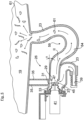
- a dishwasher with a washing compartment 1 delimiting a washing chamber is shown schematically.
- items to be cleaned (not shown) can be arranged in crockery baskets 3, 5.
- two spray arms 7, 8 provided in different spray planes are arranged by way of example, via which the items to be washed are exposed to washing liquid.
- a sump 11 with a sieve arrangement 10 which is only roughly indicated is provided in the bottom of the washing compartment.
- a circulating line 9 with a circulating pump 13 arranged therein leads away from the sump 11 .
- the circulation line 9 is fluidically connected to the spray arms 7 , 8 via supply lines 14 , 15 . Downstream of the circulating pump 13 is a heating element 12 referred to as a water heater.
- the pump sump 11 is also connected via connecting pieces to a fresh water supply line 16 coupled to the water supply network and to a drain line 17 in Connection in which a drain pump 18 for pumping washing liquid out of the washing container 1 is arranged.
- the rinsing container 1 has at his, in the 1 right side as a storage container 19 a so-called storage container, which is thermally coupled in the manner of a heat exchanger in contact with a side wall 20 of the washing compartment 1.
- Washing liquid that is no longer needed after a partial program step of a wash cycle has been carried out can be temporarily stored in the storage container 19 .
- the storage container 19 is fluidically connected in its upper region via a ventilation opening 22 to the washing area.
- a water switch shown as a three-way switching valve 25, at which a connecting line 23 branches off, which leads to the storage container 19.
- the three-way switching valve 25 connects the other hand, in one in the 2 In the switch position shown, the circulation line 9 connects to the connecting line 23 leading to the storage tank 19 and interrupts the flow path to the feed lines 14, 15.
- the rinsing liquid can be pumped into the storage tank 19 at a high flow rate and fill it until the washing liquid enters the washing container 1 via the ventilation opening 22 and is fed back along the washing container wall 20 past the crockery baskets 3, 5 back into the pump sump 11 with the associated sieve arrangement 10. To this Dirt particles, grease residues, etc. can be removed from the storage container 19 in this way.
- a storage tank valve 26 is provided so that the filling or emptying of the storage tank 19 can be controlled by means of the control device 27 .
- the valve 26 is arranged in the connecting line 23 leading to the storage tank 19 and is arranged in its open position, for example during the above-mentioned cleaning of the storage tank.
- the wash cycle can be started with a pre-wash step, in which a quantity of final rinse water temporarily stored in the storage tank 19 from the previous wash cycle is let into the pump well area of the wash tank 1 .
- the storage tank valve 26 is opened and the three-way valve 25 in the 2 switched position shown.
- the temporarily stored final rinse quantity can therefore flow into the pump sump area of the washing container 1 solely by the effect of gravity.
- the three-way switching valve 25 in its in the 1 switch position shown switched and the circulation pump 13 started, whereby the drained from the storage tank 19 rinse water can circulate.
- the rinsing liquid is pumped out by means of the drain pump 18 and then fresh water is fed into the pump well area for a subsequent cleaning step.
- the connecting line 23 is connected via an orifice 29 to a valve chamber 31 of the storage tank valve 26 .
- the valve chamber 31 is delimited radially on the outside by a socket 33 .
- the connecting piece 33 is connected to the underside of the storage container 19 via two stiffening ribs 35 .
- the valve chamber 31 also opens on its bottom side via a passage 37 into the connecting line 23 which can be connected to the water diverter 25 via a connecting piece 39 . Starting from the bottom passage 37 of the valve 26, the connecting line 23 continues vertically downwards via a U-shaped bend.
- the actuator insert 41 of the storage container valve 26 is inserted into the socket 33 delimiting the valve chamber 31 .
- the actuator insert 41 can be a thermal actuator, for example, to the valve tappet 43 of which a valve disk 45 is fastened.
- valve disk 45 In the 3 the valve disk 45 is shown in its closed position, in which the sealing points 47 of the valve disk 45 and the valve seat 49 are pressed into sealing contact.
- the valve seat 49 is drawn around the orifice opening 29 on the peripheral side.
- the valve disk 47 is according to the 3 integral part of a membrane element 51, which is formed as a substantially rotationally symmetrical silicone component.
- the rotationally symmetrical membrane element 51 is inserted with its open ring-shaped end in an annular gap between the connection piece 33 and an internal pipe piece 55 of a housing part 57 .
- the actuator insert 41 is therefore not inserted directly into the connecting piece 33, but with the interposition of the housing part 57.
- the liquid line 23 between the storage tank valve 26 and the storage tank 19 has a siphon 59, which in the 3 indicated dirt particles 61 from the valve 26 holds back.
- the siphon 59 is formed by two essentially vertically aligned line sections 62 and 63 which run in opposite directions to one another.
- the two line sections 62 , 63 are each connected directly to the outlet opening 29 of the valve 26 and to a passage opening of the storage container 19 .
- the line section 62 of the siphon 59 extends downwards directly starting from the valve 26 with an increasing angle of inclination ⁇ and merges at the siphon bottom 64 into the line section 63 leading to the storage tank 19.
- the line section 62 of the siphon 59 is thus, starting from the mouth opening 29, always inclined downwards over the angle of inclination ⁇ , as a result of which the dirt particles 61 can migrate away from the valve 26 to the siphon bottom 64 under the effect of gravity.
- the siphon base 64 is arranged below the storage container valve 26 by a height difference ⁇ h.
- the reservoir valve 26 is shown in its open position, in which the valve disk 45 is adjusted by one valve lift to the left. In this way, a flow gap between the valve disk 45 and the valve seat 49 is released.
- the washing liquid temporarily stored in the storage container 19 is thus drained from the storage container 19 under the effect of gravity and returns to the liquid circuit of the dishwasher.
- the temporarily stored washing liquid thus flows through the storage tank valve 26 in the direction of flow I.
- the height difference ⁇ h between the storage tank valve 26 and the siphon base 64 is designed in such a way that the dirt particles 61 caught on the siphon base 64 cannot be entrained by the flow I to the storage tank valve 26.
- the operating state when filling the storage container 19 with rinsing liquid or the cleaning of the storage container 19 with rinsing liquid is illustrated.
- the rinsing liquid is pumped into the storage container 19 by means of the circulating pump 13 at a high flow rate in the direction of flow II.
- the dirt particles 26 deposited on the bottom 64 of the siphon are flushed back into the storage container 19, as a result of which the siphon 59 is prevented from becoming clogged.
- the dirt particles 61 can then be discharged during a cleaning process from the storage container 19 via the ventilation opening 22 into the washing area.
Landscapes
- Engineering & Computer Science (AREA)
- Water Supply & Treatment (AREA)
- Washing And Drying Of Tableware (AREA)
Description
- Die Erfindung betrifft ein wasserführendes Haushaltsgerät, insbesondere eine Geschirrspülmaschine, mit einem Speicherbehälter, in dem Spülflüssigkeit zwischenspeicherbar ist, und mit einer Flüssigkeitsleitung, die einen Spülbehälter des wasserführenden Haushaltsgeräts mit dem Speicherbehälter verbindet, wobei in der Flüssigkeitsleitung ein Ventil angeordnet ist, das im geöffneten Zustand in einer Strömungsrichtung von Spülflüssigkeit durchströmbar ist.
- Während eines Spülgangs durchlaufen Geschirrspülmaschinen Spülprogramme, die aus einer Anzahl von Teilprogrammschritten bestehen, wie z.B. Vorspülen, Reinigen, Zwischenspülen, Klarspülen und Trocknen. Zur Verteilung von Flüssigkeit während eines Spülprogrammdurchlaufs sind im Flüssigkeitskreislauf einer Geschirrspülmaschine Ventile vorgesehen, die einen Flüssigkeitsweg öffnen oder schließen. Jedoch können Schmutzpartikel in der Flüssigkeit ein Ventil blockieren.
- Aus der
WO 2009/027364 A1 ist ein wasserführendes Haushaltsgerät bekannt, welches wenigstens aufweisend einen Behälter, in dem Spülgut mit Flüssigkeit beaufschlagbar ist, einen zur Aufnahme von Flüssigkeit vorgesehenen und mit einem als Wärmetauscher dienenden Vorratsbehälter und wenigstens ein den bestimmungsgemäßen Betrieb des Vorratsbehälters ermöglichendes und/oder zumindest unterstützendes Bauteil aufweist. Das Bauteil ist dabei in den Vorratsbehälter integriert und kann beispielsweise ein Ablaufventil sein. Der Vorratsbehälter kann auch Grobschmutzrückhalterippen aufweisen. - Die Aufgabe der Erfindung besteht darin, ein Haushaltsgerät, insbesondere Geschirrspülmaschine, bereitzustellen, bei dem ein zuverlässiger Ventilbetrieb gewährleistet ist.
- Die Erfindung geht aus von einem wasserführendes Haushaltsgerät, insbesondere eine Geschirrspülmaschine, mit einem Speicherbehälter, in dem Spülflüssigkeit zwischenspeicherbar ist, und mit einer Flüssigkeitsleitung, die einen Spülbehälter des wasserführenden Haushaltsgeräts mit dem Speicherbehälter verbindet, wobei in der Die Erfindung geht aus von einem wasserführendes Haushaltsgerät, insbesondere eine Geschirrspülmaschine, mit einem Speicherbehälter, in dem Spülflüssigkeit zwischenspeicherbar ist, und mit einer Flüssigkeitsleitung, die einen Spülbehälter des wasserführenden Haushaltsgeräts mit dem Speicherbehälter verbindet, wobei in der Flüssigkeitsleitung ein Ventil angeordnet ist, das im geöffneten Zustand in einer Strömungsrichtung von Spülflüssigkeit durchströmbar ist
- Gemäß dem kennzeichnenden Teil des Patentanspruches 1 weist die Flüssigkeitsleitung eine in der Strömungsrichtung dem Ventil vorgelagerte Schmutzpartikel auffangende Schmutzpartikelrückhalteeinrichtung auf. Hierbei kann es sich bspw. um einen Siphon oder ein Filter handeln.
- Flüssigkeitsleitung ein Ventil angeordnet ist, das im geöffneten Zustand in einer Strömungsrichtung von Spülflüssigkeit durchströmbar ist
- Gemäß Patentanspruch 1 weist die Flüssigkeitsleitung eine in der Strömungsrichtung dem Ventil vorgelagerte Schmutzpartikel auffangende Schmutzpartikelrückhalteeinrichtung auf. Hierbei handelt es sich um einen Siphon.
- In dem Speicherbehälter kann Spülflüssigkeit zwischengespeichert werden, die nach Ausführung eines Teilprogrammschrittes eines Spülgangs nicht mehr benötigt wird. Die nicht mehr benötigte Spülflüssigkeit wird vom Spülraum mittels einer Umwälzpumpe sowie bei geöffnetem Speicherbehälterventil in den Speicherbehälter gepumpt. Anschließend wird das Speicherbehälterventil geschlossen und bspw. bis zum nächsten Spülgang zwischengespeichert und beim nächsten Spülgang zum Vorspülen des Spülgutes eingesetzt werden. Um das Befüllen und Entleeren des Speicherbehälters zu steuern, ist ein Speicherbehälterventil vorgesehen, mit dem eine Regeleinrichtung der Geschirrspülmaschine den Flüssigkeitsweg zum Speicherbehälter öffnen oder schließen kann.
- Durch die Schmutzpartikelrückhalteeinrichtung bleibt das Ventil weitgehend frei von zumindest größeren Schmutzpartikeln, die sich ansonsten im Ventil festsetzen könnten. Die Anordnung des Ventils mit zugeordnetem Siphon ist daher vor allem im Schmutz- und Brauchwasserbereich eines wasserführenden Haushaltsgerätes, insbesondere einer Geschirrspülmaschine, einsetzbar.
- Der Siphon kann bspw. als Röhrensiphon ausgebildet sein und zwei im Wesentlichen vertikal ausgerichtete, zueinander gegenläufige Leitungsabschnitte aufweisen, von denen einer unmittelbar mit dem Ventil verbunden ist. Die beiden gegenläufigen Leitungsabschnitte des Siphons sind über einen Siphonboden miteinander verbunden, auf dem sich die Schmutzpartikel sammeln.
- Der Siphon kann dem Ventil in Strömungsrichtung derart vorgeschaltet sein, dass sich der mit dem Ventil gekoppelte Siphon-Leitungsabschnitt unmittelbar ausgehend von dem Ventil mit einem vorgegebenen Neigungswinkel nach unten bis zum Siphonboden erstrecken kann. Der Neigungswinkel des Siphon-Leitungsabschnittes kann dabei veränderlich sein, zum Beispiel in Richtung auf den Siphonboden größer werden. Die sich in dem Siphon-Leitungsabschnitt sammelnden Schmutzpartikel können daher aufgrund des Leitungsgefälles in Richtung auf den Siphonboden, das heißt weg von dem Ventil, wandern.
- Der Siphon kann mit seinem entsprechenden Leitungsabschnitt in einen Ventilraum des Ventils einmünden. Innerhalb des Ventilraums kann sich ein Ventilelement, etwa ein Ventilteller verstellen, um den flüssigkeitsdurchströmten Ventilraum zu öffnen oder zu schließen. Die Mündungsöffnung des Ventils kann von einem, mit dem Ventilelement zusammenwirkenden Ventilsitz randseitig begrenzt sein. Im geschlossenen Zustand kann das verstellbare Ventilelement flüssigkeitsdicht in Anlage mit dem Ventilsitz gedrückt sein. Im geöffneten Zustand des Ventils kann dagegen das Ventilelement über einen Ventilhub vom Ventilsitz weg verstellt sein, wodurch ein Strömungsspalt zur Mündungsöffnung freigelegt ist, der die Flüssigkeitsströmung durch das Ventil ermöglicht.
- Die sich im geschlossenen Zustand des Ventils ergebende Dichtfläche zwischen dem Ventilsitz und dem verstellbaren Ventilelement muss im Wesentlichen frei von Schmutzpartikeln sein, um eine einwandfreie Funktionsweise des Ventils zu gewährleisten. Hierbei hat es sich als günstig erwiesen, wenn die Dichtfläche nicht in einer horizontalen Ebene ausgerichtet ist, sondern vielmehr gegenüber einer solchen horizontalen Ebene geneigt ist, und insbesondere in einer vertikalen Ebene ausgerichtet ist. Schmutzpartikel können sich somit weder auf der Dichtfläche des Ventilsitzes noch auf der Dichtfläche des zugeordneten Ventilelementes dauerhaft absetzen und zu einem Verkleben des Ventilelementes am Ventilsitz führen.
- Um eine aufgabengemäße Wirkung des Siphons zu gewährleisten, ist es von Vorteil, wenn der Siphonboden um eine vorgegebene Höhendifferenz unterhalb des Ventils, insbesondere unterhalb der oben erwähnten Mündungsöffnung in den Ventilraum angeordnet ist. Die Höhendifferenz ergibt sich aus den Strömungsverhältnissen in der Flüssigkeitsleitung, insbesondere aus der Strömungsgeschwindigkeit der Flüssigkeitsströmung. Bei größerer Flüssigkeitsströmung ist die Höhendifferenz zwischen Ventil und Siphonboden entsprechend zu vergrößern, damit die am Siphonboden aufgefangenen Schmutzpartikel nicht bis zum Ventil gefördert werden können.
- Um ein Abführen von bereits innerhalb des Ventils befindlichen Schmutzpartikeln zu unterstützen, kann es von Vorteil sein, wenn die Flüssigkeitsleitung stromab des Ventils vertikal nach unten weitergeführt wird. Die Schmutzpartikel können sich daher zusätzlich durch Schwerkraftwirkung aus dem Ventilraum des Ventils verlagern. Vor diesem Hintergrund ist es besonders bevorzugt, wenn der Ventilraum des Ventils bodenseitig einen Durchlass aufweist, an dem sich die Flüssigkeitsleitung stromab des Ventils anschließen kann.
- Das Speicherbehälterventil ist strömungstechnisch zwischen dem Spülbehälter und dem Speicherbehälter, das heißt im Schmutz- oder Brauchwasserbereich der Geschirrspülmaschine, angeordnet. Hier besteht die Problematik, dass bei geöffnetem Ventil Schmutzpartikel innerhalb des Speicherbehälterventils hängenbleiben und sich dort festsetzen können. In diesem Fall kann es zu einer Störung oder Undichtheit am Ventil und somit zu einer Fehlfunktion des Speicherbehälters kommen.
- Zur Rückführung der zwischengespeicherten Spülflüssigkeit in den Flüssigkeitskreislauf der Geschirrspülmaschine wird das Speicherbehälterventil geöffnet, wodurch die Spülflüssigkeit aus dem Speicherbehälter strömen kann. Die Spülflüssigkeit kann dabei unter Schwerkraftwirkung, das heißt mit geringer Geschwindigkeit, vom Speicherbehälter in den Spülraum der Geschirrspülmaschine einströmen.
- Das Ablassen der zwischengespeicherten Spülflüssigkeit aus dem Speicherbehälter ist im Hinblick auf eine Störung des Speicherbehälterventils kritisch. In diesem Fall besteht nämlich die Gefahr, dass Schmutzpartikel aus dem Speicherbehälter mitgerissen werden und das Speicherbehälterventil zusetzen können. Der erfindungsgemäße Siphon kann daher insbesondere strömungstechnisch zwischen dem Speicherbehälterventil und dem Speicherbehälter geschaltet sein, um diese Schmutzpartikel aufzufangen.
- Das Ablassen der zwischengespeicherten Spülflüssigkeit aus dem Speicherbehälter kann, wie bereits oben erwähnt, unter Schwerkraft erfolgen, das heißt mit entsprechend geringer Strömungsgeschwindigkeit. Entsprechend reduziert kann auch der geodätische Höhenunterschied zwischen dem Speicherbehälterventil und dem Siphonboden bemessen sein.
- Demgegenüber wird beim Befüllen des Speicherbehälters Spülflüssigkeit mittels der Umwälzpumpe bei großer Geschwindigkeit in den Speicherbehälter gepumpt. Auf diese Weise wird der Siphonboden regelmäßig mit großer Flüssigkeitsgeschwindigkeit durchspült, wodurch ein Verstopfen des Siphons vermieden werden kann.
- Es ist aber auch möglich, den Siphon anstelle als Röhrensiphon als Flaschen-, Trennwand- oder Glockensiphon auszubilden.
- In einer weiteren Ausführungsform ist vorzugsweise vorgesehen, dass die Schmutzpartikelrückhalteeinrichtung ein Filter aufweist, mit dem Schmutzpartikel zurückgehalten werden können, die insbesondere eine den zuverlässigen Betrieb des Ventils störenden Mindestgröße aufweisen.
- In einer Weiterbildung ist vorgesehen, dass das Filter durch Rückspülen reinigbar ist, so dass ein Verstopfen des Filters zuverlässig unterbunden ist.
- Ferner ist in einer Weiterbildung vorgesehen, dass das Rückspülen durch wenigstens teilweises Entleeren eines Speicherbehälters bewirkbar ist, in dem Spülflüssigkeit zwischenspeicherbar ist, und dass die Flüssigkeitsleitung einen Spülbehälter des wasserführenden Haushaltsgeräts mit dem Speicherbehälter verbindet. Es wird mit dem Entleeren des Speicherbehälters eine Flüssigkeitsströmung erzeugt, die entgegengesetzt zu der Strömungsrichtung ist, in der das Filter beim Befüllen des Speicherbehälters durchströmt wird. Anschließend kann bspw. durch Betrieb der Laugenpumpe diese mit Schmutzpartikeln versetzte Flüssigkeitsmenge aus dem Haushaltsgerät in ein hausseitiges Abwasserentsorgungsnetz gefördert werden.
- In einer weiteren Ausführungsform ist vorzugsweise vorgesehen, dass die Schmutzpartikelrückhalteeinrichtung einen Fliehkraftabscheider aufweist, mit dem eine rotierende Flüssigkeitsströmung erzeugt werden kann, durch Schmutzpartikel abgetrennt werden können.
- Schließlich ist vorzugsweise vorgesehen, dass eine in der ersten Strömungsrichtung vorliegende Spülflüssigkeitsströmung der Speicherbehälter entleerbar ist. So wird das Ventil vor aus dem vollem Speicherbehälter herausgeförderten Schmutzpartikel geschützt, die sich bspw. erst durch z.B. biologische Prozesse gebildet haben. Es ist jedoch auch möglich, dass die Schmutzpartikelrückhalteeinrichtung Schmutzpartikel beim Füllen des Speicherbehälters zurückhält.
- Nachfolgend ist ein Ausführungsbeispiel der Erfindung anhand der beigefügten Figuren beschrieben.
- Es zeigen:
- Fig. 1
- in einem schematischen Blockdiagramm eine Geschirrspülmaschine mit einem Speicherbehälter;
- Fig. 2
- eine Ansicht entsprechend der
Fig. 1 , in der eine Reinigung des Speicherbehälters veranschaulicht ist; - Fig. 3
- in einer vergrößerten Seitenschnittdarstellung das Speicherbehälterventil mit zugeordnetem Siphon; sowie
- Fig. 4 und 5
- jeweils in Ansichten entsprechend der
Fig. 3 bei unterschiedlichen Betriebszuständen der Geschirrspülmaschine. - In der
Fig. 1 ist schematisch eine Geschirrspülmaschine mit einem, einen Spülraum begrenzenden Spülbehälter 1 gezeigt. Im Spülraum des Spülbehälters 1 kann ein nicht dargestelltes, zu reinigendes Spülgut in Geschirrkörben 3, 5 angeordnet werden. Im gezeigten Spülbehälter 1 sind beispielhaft zwei, in unterschiedlichen Sprühebenen vorgesehene Sprüharme 7, 8 angeordnet, über die das Spülgut mit Spülflüssigkeit beaufschlagt wird. Im Spülbehälterboden ist ein Pumpentopf 11 mit einer nur grob angedeuteten Siebanordnung 10 vorgesehen. Vom Pumpentopf 11 ist eine Umwälzleitung 9 mit darin angeordneter Umwälzpumpe 13 weggeführt. Die Umwälzleitung 9 ist über Zuleitungen 14, 15 strömungstechnisch mit den Sprüharmen 7, 8 verbunden. Der Umwälzpumpe 13 nachgeschaltet ist ein, als Wasserheizung bezeichnetes Heizelement 12. - Der Pumpentopf 11 ist außerdem über Anschlussstutzen mit einer, mit dem Wasserversorgungsnetz gekoppelten Frischwasser-Zuleitung 16 sowie mit einer Ablaufleitung 17 in Verbindung, in der eine Laugenpumpe 18 zum Abpumpen von Spülflüssigkeit aus dem Spülbehälter 1 angeordnet ist. Der Spülbehälter 1 weist an seiner, in der
Fig. 1 rechten Seite als Speicherbehälter 19 einen sogenannten Speicherbehälter auf, der nach Art eines Wärmetauschers thermisch gekoppelt in Anlage mit einer Seitenwand 20 des Spülbehälters 1 ist. - In dem Speicherbehälter 19 kann Spülflüssigkeit zwischengespeichert werden, die nach Ausführung eines Teilprogrammschrittes eines Spülganges nicht mehr benötigt wird. Der Speicherbehälter 19 ist in seinem oberen Bereich über eine Be- und Entlüftungsöffnung 22 strömungstechnisch in Verbindung mit dem Spülraum.
- Während der Durchführung eines Spülgangs sind im Flüssigkeitskreislauf unter anderem der Pumpentopf 11 mit zugeordneter Siebanordnung 10, die Umwälzleitung 9, die Zuleitungen 14, 15 sowie die beiden Sprüharme 7, 8 integriert.
- Stromab des Heizelementes 12 ist in der Umwälzleitung 9 eine als Drei-Wege-Schaltventil 25 dargestellte Wasserweiche vorgesehen, an der eine Verbindungsleitung 23 abzweigt, die zum Speicherbehälter 19 führt.
- In der in der
Fig. 1 gezeigten Schaltstellung des Drei-Wege-Schaltventils 25 ist die Verbindung zum Speicherbehälter 19 unterbrochen und die Umwälzleitung 9 mit den Zuleitungen 14, 15 verbunden. In dieser Schaltstellung des Drei-Wege-Schaltventils 25 kann daher die Spülflüssigkeit zur Durchführung des Spülgangs in der Geschirrspülmaschine zirkuliert werden. - Das Drei-Wege-Schaltventil 25 verbindet demgegenüber in einer in der
Fig. 2 gezeigten Schaltstellung die Umwälzleitung 9 mit der, zum Speicherbehälter 19 führenden Verbindungsleitung 23 und unterbricht den Strömungsweg zu den Zuleitungen 14, 15. In dieser Schaltstellung kann zur Reinigung des Speicherbehälters 19 die Spülflüssigkeit mit hoher Strömungsgeschwindigkeit in den Speicherbehälter 19 gepumpt werden und diesen füllen, bis die Spülflüssigkeit über die Be- und Entlüftungsöffnung 22 in den Spülbehälter 1 eintritt und entlang der Spülbehälterwand 20 vorbei an den Geschirrkörben 3, 5 wieder in den Pumpentopf 11 mit zugeordneter Siebanordnung 10 rückgeführt wird. Auf diese Weise können Schmutzpartikel, Fettrückstände, etc. aus dem Speicherbehälter 19 geführt werden. - Damit das Befüllen oder Entleeren des Speicherbehälters 19 mittels der Regeleinrichtung 27 gesteuert werden kann, ist ein Speicherbehälterventil 26 vorgesehen. Das Ventil 26 ist in der zum Speicherbehälter 19 führenden Verbindungsleitung 23 angeordnet und zum Beispiel während der oben genannten Speicherbehälter-Reinigung in seiner OffenStellung angeordnet.
- Beispielhaft kann der Spülgang mit einem Vorspülschritt gestartet werden, bei dem eine im Speicherbehälter 19 zwischengespeicherte Klarspülwassermenge vom vorangegangenen Spülgang in den Pumpentopfbereich des Spülbehälters 1 eingelassen wird. Hierzu wird das Speicherbehälterventil 26 geöffnet und das Drei-Wege-Ventil 25 in die in der
Fig. 2 gezeigte Stellung geschaltet. Die zwischengespeicherte Klarspülmenge kann daher alleine durch Schwerkraftwirkung in den Pumpentopfbereich des Spülbehälters 1 einströmen. - Anschließend wird das Drei-Wege-Schaltventil 25 in seine in der
Fig. 1 gezeigte Schaltstellung geschaltet sowie die Umwälzpumpe 13 gestartet, wodurch das vom Speicherbehälter 19 abgelassene Klarspülwasser zirkulieren kann. Nach Ausführung des Vorspülschrittes wird die Spülflüssigkeit mittels der Laugenpumpe 18 abgepumpt und anschließend Frischwasser für einen folgenden Reinigungsschritt in den Pumpentopfbereich zugeführt. - Wie aus der
Fig. 3 hervorgeht, ist die Verbindungsleitung 23 über eine Mündungsöffnung 29 mit einem Ventilraum 31 des Speicherbehälterventils 26 in Verbindung. Der Ventilraum 31 ist radial außenseitig mit einem Stutzen 33 begrenzt. Der Stutzen 33 ist über zwei Versteifungsrippen 35 mit der Unterseite des Speicherbehälters 19 in Verbindung. Der Ventilraum 31 mündet außerdem an seiner Bodenseite über einen Durchlass 37 wiederum in die Verbindungsleitung 23, die über einen Anschlussstutzen 39 an der Wasserweiche 25 anschließbar ist. Die Verbindungsleitung 23 ist dabei ausgehend vom bodenseitigen Durchlass 37 des Ventils 26 über eine U-förmige Biegung vertikal nach unten weitergeführt. - In den, den Ventilraum 31 begrenzenden Stutzen 33 ist ein Stelltrieb-Einsatzteil 41 des Speicherbehälterventils 26 eingesetzt. Das Stelltrieb-Einsatzteil 41 kann beispielhaft ein Thermoaktuator sein, an dessen Ventilstößel 43 ein Ventilteller 45 befestigt ist.
- In der
Fig. 3 ist der Ventilteller 45 in seiner Schließstellung gezeigt, in der die Dichtstellen 47 des Ventiltellers 45 und des Ventilsitzes 49 in Dichtanlage gedrückt sind. Der Ventilsitz 49 ist umfangsseitig um die Mündungsöffnung 29 gezogen. Dabei sind die Dichtstellen bzw. Dichtflächen 47 des Ventilsitzes 49 und des Ventiltellers 45 gemäß derFig. 3 in einer vertikalen Ebene ausgerichtet. - Der Ventilteller 47 ist gemäß der
Fig. 3 integraler Bestandteil eines Membranelementes 51, das als ein im Wesentlichen rotationsymmetrisches Silikonbauteil gebildet ist. Das rotationssymmetrische Membranelement 51 ist mit seinem offenen ringförmigen Ende in einem Ringspalt zwischen dem Anschlussstutzen 33 und einem innenliegenden Rohrstutzen 55 eines Gehäuseteils 57 eingesetzt. Das Stelltrieb-Einsatzteil 41 ist daher nicht unmittelbar in den Anschlussstutzen 33 eingesetzt, sondern unter Zwischenlage des Gehäuseteils 57. - Wie aus der
Fig. 3 weiter hervorgeht, weist die Flüssigkeitsleitung 23 zwischen dem Speicherbehälterventil 26 und dem Speicherbehälter 19 ein Siphon 59 auf, das die in derFig. 3 angedeuteten Schmutzpartikel 61 vom Ventil 26 zurückhält. Der Siphon 59 ist durch zwei im Wesentlichen vertikal ausgerichteten Leitungsabschnitten 62 und 63 gebildet, die zueinander gegenläufig verlaufen. Die beiden Leitungsabschnitte 62, 63 sind dabei unmittelbar jeweils an der Mündungsöffnung 29 des Ventils 26 sowie an einer Durchlassöffnung des Speicherbehälters 19 verbunden. Der Leitungsabschnitt 62 des Siphons 59 erstreckt sich dabei unmittelbar ausgehend vom Ventil 26 mit einem ansteigenden Neigungswinkel α nach unten und geht am Siphonboden 64 über in den zum Speicherbehälter 19 führenden Leitungsabschnitt 63. - Der Leitungsabschnitt 62 des Siphons 59 ist somit ausgehend von der Mündungsöffnung 29 stets über den Neigungswinkel α nach unten geneigt, wodurch die Schmutzpartikel 61 unter Schwerkraftwirkung weg vom Ventil 26 zum Siphonboden 64 wandern können. Der Siphonboden 64 ist dabei um eine Höhendifferenz Δh unterhalb des Speicherbehälterventils 26 angeordnet.
- Nachfolgend werden anhand der
Fig. 3 bis 5 unterschiedliche Betriebszustände der Geschirrspülmaschine beschrieben. So ist in derFig. 3 das Speicherbehälterventil 26 in seiner geschlossenen Stellung gezeigt, wodurch die vorher in den Speicherbehälter 19 gepumpte Spülflüssigkeit zwischengespeichert werden kann. Die im Speicherbehälter 19 sowie in der Verbindungsleitung 23 vorhandenen Schmutzpartikel 61 lagern sich daher im Laufe der Zeit am Boden des Speicherbehälters 19 und/oder am Siphonboden 64 ab. Das Speicherbehälterventil 26 bleibt dabei im Bereich der Dichtflächen 47 weitgehend frei von Schmutzpartikeln 61. - In der
Fig. 4 ist das Speicherbehälterventil 26 in seiner geöffneten Stellung gezeigt, in der der Ventilteller 45 um einen Ventilhub nach links verstellt ist. Auf diese Weise ist ein Strömungsspalt zwischen dem Ventilteller 45 und dem Ventilsitz 49 freigegeben. Die im Speicherbehälter 19 zwischengespeicherte Spülflüssigkeit wird somit unter Schwerkraftwirkung aus dem Speicherbehälter 19 abgelassen und gelangt zurück in den Flüssigkeitskreislauf der Geschirrspülmaschine. Die zwischengespeicherte Spülflüssigkeit durchströmt somit in der Strömungsrichtung I das Speicherbehälterventil 26. Der Höhenunterschied Δh zwischen dem Speicherbehälterventil 26 und dem Siphonboden 64 ist dabei so ausgelegt, dass die am Siphonboden 64 aufgefangenen Schmutzpartikel 61 durch die Strömung I nicht bis zum Speicherbehälterventil 26 mitgerissen werden können. - In der
Fig. 5 ist demgegenüber der Betriebszustand beim Befüllen des Speicherbehälters 19 mit Spülflüssigkeit bzw. die Reinigung des Speicherbehälters 19 mit Spülflüssigkeit veranschaulicht. In diesem Fall wird die Spülflüssigkeit mittels der Umwälzpumpe 13 unter großer Strömungsgeschwindigkeit in der Strömungsrichtung II in den Speicherbehälter 19 gepumpt. Auf diese Weise werden die am Siphonboden 64 abgelagerten Schmutzpartikel 26 wieder zurück in den Speicherbehälter 19 gespült, wodurch ein Verstopfen des Siphons 59 vermieden ist. Die Schmutzpartikel 61 können dann während eines Reinigungsvorganges aus dem Speicherbehälter 19 über die Be- und Entlüftungsöffnung 22 in den Spülraum ausgetragen werden. -
- 1
- Spülbehälter
- 3, 5
- Geschirrkörbe
- 7,8
- Sprüharme
- 9
- Umwälzleitung
- 10
- Siebanordnung
- 11
- Pumpentopf
- 12
- Heizelement
- 13
- Umwälzpumpe
- 14, 15
- Zuleitungen
- 16
- Frischwasser-Zuleitung
- 17
- Ablaufleitung
- 18
- Laugenpumpe
- 19
- Speicherbehälter
- 20
- Spülbehälter-Seitenwand
- 22
- Be- und Entlüftungsöffnung
- 23
- Verbindungsleitung
- 25
- Drei-Wege-Schaltventil
- 26
- Speicherbehälterventil
- 27
- Regeleinrichtung
- 29
- Mündungsöffnung
- 31
- Ventilraum
- 33
- Anschlussstutzen
- 37
- Durchlass
- 39
- Stutzen
- 41
- Stelltrieb-Einsatzteil
- 43
- Ventilstößel
- 45
- Schließelement
- 47
- Dichtstellen
- 49
- Ventilsitz
- 51
- Membranelement
- 55
- Rohrstutzen
- 57
- Gehäuseteil
- 59
- Siphon
- 61
- Schmutzpartikel
- 62, 63
- Leitungsabschnitte
- 64
- Siphonboden
- I, II
- Strömungsrichtungen
- Δh
- Höhenunterschied
- α
- Neigungswinkel
Claims (11)
- Wasserführendes Haushaltsgerät, insbesondere Geschirrspülmaschine, mit einem Speicherbehälter (19), in dem Spülflüssigkeit zwischenspeicherbar ist, und mit einer Flüssigkeitsleitung (23), die einen Spülbehälter (1) des wasserführenden Haushaltsgeräts mit dem Speicherbehälter (19) verbindet, wobei in der Flüssigkeitsleitung (23) ein Ventil (26) angeordnet ist, das im geöffneten Zustand in einer Strömungsrichtung (I) von Spülflüssigkeit durchströmbar ist, wobei die Flüssigkeitsleitung (23) eine in der Strömungsrichtung (I) dem Ventil (26) vorgelagerte Schmutzpartikel (61) auffangende Schmutzpartikelrückhalteeinrichtung aufweist, dadurch gekennzeichnet, dass die Schmutzpartikelrückhalteeinrichtung ein Siphon (59) mit zwei im Wesentlichen vertikal ausgerichteten Leitungsabschnitten (62, 63) ist, von denen einer mit dem Ventil (26) verbunden ist.
- Wasserführendes Haushaltsgerät nach Anspruch 1, dadurch gekennzeichnet, dass einer der Leitungsabschnitte (62) des Siphons (59) über eine Mündungsöffnung (29) in einen Ventilraum (31) des Ventils (26) mündet, der mit einem Ventilelement (45) schließbar ist.
- Wasserführendes Haushaltsgerät nach Anspruch 2, dadurch gekennzeichnet, dass die Mündungsöffnung (29) von einem mit dem Ventilelement (45) zusammenwirkenden Ventilsitz (49) begrenzt ist, wobei die Dichtflächen (47) des Ventilsitzes (49) und des Ventilelements (45) gegenüber einer horizontalen Ebene geneigt sind, und insbesondere im Wesentlichen in einer vertikalen Ebene ausgerichtet sind.
- Wasserführendes Haushaltsgerät nach einem der Ansprüche 1 bis 3, dadurch gekennzeichnet, dass der Leitungsabschnitt (62) des Siphons sich ausgehend von dem Ventil (26) mit einem Neigungswinkel (α) nach unten bis zum Siphonboden (64) erstreckt.
- Wasserführendes Haushaltsgerät nach einem der vorhergehenden Ansprüche, dadurch gekennzeichnet, dass ein Siphonboden (64) um eine Höhendifferenz (Δh) unterhalb des Ventils (41), insbesondere unterhalb der Mündungsöffnung (29) des Ventils (41) angeordnet ist.
- Wasserführendes Haushaltsgerät nach einem der vorhergehenden Ansprüche, dadurch gekennzeichnet, dass die Flüssigkeitsleitung (23) in der Strömungsrichtung (I) stromab des Ventils (26) nach unten geführt ist, wobei der Ventilraum (31) des Ventils (26) über einen bodenseitigen Durchlass (37) mit der Flüssigkeitsleitung (23) stromab des Ventils (26) verbunden ist.
- Wasserführendes Haushaltsgerät nach einem der vorhergehenden Ansprüche, dadurch gekennzeichnet, dass ein zweiter Leitungsabschnitt (63) des Siphons (59) in den Speicherbehälter (19) mündet.
- Wasserführendes Haushaltsgerät nach einem der vorhergehenden Ansprüche, dadurch gekennzeichnet, dass in der ersten Strömungsrichtung (I) die im Speicherbehälter (19) zwischengespeicherte Spülflüssigkeit, insbesondere unter Schwerkraftwirkung, vom Speicherbehälter (19) in einen Spülraum der Geschirrspülmaschine einströmt.
- Wasserführendes Haushaltsgerät nach einem der vorhergehenden Ansprüche, dadurch gekennzeichnet, dass in einer entgegen gesetzten zweiten Strömungsrichtung (II) die Spülflüssigkeit mittels einer Umwälzpumpe (13) mit hoher Strömungsgeschwindigkeit in den Speicherbehälter (19) förderbar ist.
- Wasserführendes Haushaltsgerät nach einem der vorhergehenden Ansprüche, dadurch gekennzeichnet, dass die Schmutzpartikelrückhalteeinrichtung als Flaschen-, Trennwand- oder Glockensiphon ausgebildet ist.
- Wasserführendes Haushaltsgerät nach einem der vorhergehenden Ansprüche, dadurch gekennzeichnet, dass durch eine in Strömungsrichtung (I) vorliegende Spülflüssigkeitsströmung der Speicherbehälter (19) entleerbar ist.
Applications Claiming Priority (1)
| Application Number | Priority Date | Filing Date | Title |
|---|---|---|---|
| DE102009028278A DE102009028278A1 (de) | 2009-08-06 | 2009-08-06 | Wasserführendes Haushaltsgerät |
Publications (3)
| Publication Number | Publication Date |
|---|---|
| EP2283762A2 EP2283762A2 (de) | 2011-02-16 |
| EP2283762A3 EP2283762A3 (de) | 2014-01-15 |
| EP2283762B1 true EP2283762B1 (de) | 2023-09-06 |
Family
ID=43402167
Family Applications (1)
| Application Number | Title | Priority Date | Filing Date |
|---|---|---|---|
| EP10170429.4A Active EP2283762B1 (de) | 2009-08-06 | 2010-07-22 | Wasserführendes Haushaltsgerät |
Country Status (3)
| Country | Link |
|---|---|
| EP (1) | EP2283762B1 (de) |
| DE (1) | DE102009028278A1 (de) |
| PL (1) | PL2283762T3 (de) |
Families Citing this family (27)
| Publication number | Priority date | Publication date | Assignee | Title |
|---|---|---|---|---|
| US9918609B2 (en) | 2009-12-21 | 2018-03-20 | Whirlpool Corporation | Rotating drum filter for a dishwashing machine |
| US8746261B2 (en) | 2009-12-21 | 2014-06-10 | Whirlpool Corporation | Rotating drum filter for a dishwashing machine |
| US9687135B2 (en) | 2009-12-21 | 2017-06-27 | Whirlpool Corporation | Automatic dishwasher with pump assembly |
| US8667974B2 (en) | 2009-12-21 | 2014-03-11 | Whirlpool Corporation | Rotating filter for a dishwashing machine |
| US9119515B2 (en) | 2010-12-03 | 2015-09-01 | Whirlpool Corporation | Dishwasher with unitary wash module |
| US8627832B2 (en) | 2010-12-13 | 2014-01-14 | Whirlpool Corporation | Rotating filter for a dishwashing machine |
| US20120118336A1 (en) * | 2010-11-16 | 2012-05-17 | Whirlpool Corporation | Dishwasher with filter cleaning assembly |
| US9668636B2 (en) | 2010-11-16 | 2017-06-06 | Whirlpool Corporation | Method and apparatus for dishwasher with common heating element for multiple treating chambers |
| US9113766B2 (en) | 2010-11-16 | 2015-08-25 | Whirlpool Corporation | Method and apparatus for dishwasher with common heating element for multiple treating chambers |
| US9034112B2 (en) | 2010-12-03 | 2015-05-19 | Whirlpool Corporation | Dishwasher with shared heater |
| US9107559B2 (en) | 2011-05-16 | 2015-08-18 | Whirlpool Corporation | Dishwasher with filter assembly |
| US8733376B2 (en) | 2011-05-16 | 2014-05-27 | Whirlpool Corporation | Dishwasher with filter assembly |
| US9265401B2 (en) | 2011-06-20 | 2016-02-23 | Whirlpool Corporation | Rotating filter for a dishwashing machine |
| US9861251B2 (en) | 2011-06-20 | 2018-01-09 | Whirlpool Corporation | Filter with artificial boundary for a dishwashing machine |
| US20120318296A1 (en) | 2011-06-20 | 2012-12-20 | Whirlpool Corporation | Ultra micron filter for a dishwasher |
| US9005369B2 (en) | 2011-06-20 | 2015-04-14 | Whirlpool Corporation | Filter assembly for a dishwasher |
| US9010344B2 (en) | 2011-06-20 | 2015-04-21 | Whirlpool Corporation | Rotating filter for a dishwashing machine |
| US9301667B2 (en) | 2012-02-27 | 2016-04-05 | Whirlpool Corporation | Soil chopping system for a dishwasher |
| US9730570B2 (en) | 2012-05-30 | 2017-08-15 | Whirlpool Corporation | Reduced sound with a rotating filter for a dishwasher |
| US9237836B2 (en) | 2012-05-30 | 2016-01-19 | Whirlpool Corporation | Rotating filter for a dishwasher |
| US9532700B2 (en) | 2012-06-01 | 2017-01-03 | Whirlpool Corporation | Dishwasher with overflow conduit |
| US9451862B2 (en) | 2012-06-01 | 2016-09-27 | Whirlpool Corporation | Dishwasher with unitary wash module |
| US9833120B2 (en) | 2012-06-01 | 2017-12-05 | Whirlpool Corporation | Heating air for drying dishes in a dishwasher using an in-line wash liquid heater |
| US9554688B2 (en) | 2012-10-23 | 2017-01-31 | Whirlpool Corporation | Rotating filter for a dishwasher and methods of cleaning a rotating filter |
| EP2807971B1 (de) | 2013-05-28 | 2017-08-23 | Vestel Beyaz Esya Sanayi Ve Ticaret A.S. | Speichersystem |
| CN113494612A (zh) * | 2020-04-01 | 2021-10-12 | 青岛海尔洗碗机有限公司 | 一种水阀结构及洗碗机 |
| FR3143307A1 (fr) * | 2022-12-16 | 2024-06-21 | Everever | Cuve de lave-vaisselle |
Citations (2)
| Publication number | Priority date | Publication date | Assignee | Title |
|---|---|---|---|---|
| JPH06189885A (ja) * | 1992-12-22 | 1994-07-12 | Sanyo Electric Co Ltd | 食器洗い機 |
| WO2009027364A1 (de) * | 2007-08-31 | 2009-03-05 | BSH Bosch und Siemens Hausgeräte GmbH | Wasserführendes haushaltsgerät |
Family Cites Families (2)
| Publication number | Priority date | Publication date | Assignee | Title |
|---|---|---|---|---|
| DE3316716C2 (de) * | 1983-05-06 | 1985-11-07 | Bosch-Siemens Hausgeräte GmbH, 7000 Stuttgart | Verfahren zur Rückgewinnung von Abwärme bei einer Haushalt-Geschirrspülmaschine sowie derartige Maschine zur Durchführung des Verfahrens |
| IT1296334B1 (it) * | 1997-10-27 | 1999-06-25 | Electrolux Zanussi Elettrodome | Lavatrice automatica con sistema di recupero energetico |
-
2009
- 2009-08-06 DE DE102009028278A patent/DE102009028278A1/de not_active Withdrawn
-
2010
- 2010-07-22 EP EP10170429.4A patent/EP2283762B1/de active Active
- 2010-07-22 PL PL10170429.4T patent/PL2283762T3/pl unknown
Patent Citations (2)
| Publication number | Priority date | Publication date | Assignee | Title |
|---|---|---|---|---|
| JPH06189885A (ja) * | 1992-12-22 | 1994-07-12 | Sanyo Electric Co Ltd | 食器洗い機 |
| WO2009027364A1 (de) * | 2007-08-31 | 2009-03-05 | BSH Bosch und Siemens Hausgeräte GmbH | Wasserführendes haushaltsgerät |
Also Published As
| Publication number | Publication date |
|---|---|
| EP2283762A2 (de) | 2011-02-16 |
| EP2283762A3 (de) | 2014-01-15 |
| DE102009028278A1 (de) | 2011-02-10 |
| PL2283762T3 (pl) | 2024-04-08 |
Similar Documents
| Publication | Publication Date | Title |
|---|---|---|
| EP2283762A2 (de) | Wasserführendes Haushaltsgerät | |
| DE102007061038B4 (de) | Wasserführendes Haushaltsgerät | |
| DE102012103434B4 (de) | Ultramikron-Filter für einen Geschirrspüler | |
| EP2230985B1 (de) | Wasserführendes haushaltsgerät | |
| DE102007060197B4 (de) | Wasserführendes Haushaltsgerät | |
| EP2478818B1 (de) | Geschirrspülmaschine mit Siebreinigungseinrichtung | |
| WO2009077280A1 (de) | Wasserführendes haushaltsgerät | |
| DE102013103264A1 (de) | Geschirrspüler mit Überlaufkanal | |
| DE102008057178A1 (de) | Anlage zum Spülen von Spülgut und Verfahren zum Betreiben einer solchen Anlage | |
| WO2009077290A1 (de) | Wasserführendes haushaltsgerät mit einem selbstreinigenden filtersystem | |
| DE2323551A1 (de) | Geschirrspueler mit mitteln zum sammeln und abfuehren von speiseresten | |
| DE102011081246A1 (de) | Spülmaschine sowie Verfahren zum automatischen Reinigen einer Spülmaschine | |
| DE102007046073A1 (de) | Geschirrspüler | |
| EP2461731B1 (de) | Wasserführendes haushaltsgerät | |
| DE102011077083B4 (de) | Geschirrspülmaschine, insbesondere Haushaltsgeschirrspülmaschine | |
| US9339166B2 (en) | Dishwasher appliance and a method for operating the same | |
| DE69735228T2 (de) | Filtereinrichtung mit automatischer Reinigungsvorrichtung für Geschirrspülmaschine | |
| DE102010063711A1 (de) | Spülmaschine mit automatischer Schmutzaustragung | |
| EP2283763A2 (de) | Wasserführendes Haushaltsgerät | |
| DE102005058267B4 (de) | Konstruktion zum Verhindern einer Selbst-Wasserentleerung einer Gechirrspülmaschine | |
| DE202006020580U1 (de) | Gewerbliche Geschirrspülmaschine in Form eines Programmautomaten | |
| DE1293424B (de) | Geschirrspuelmaschine | |
| DE102006011958B4 (de) | Geschirrspülmaschine und Steuerungsverfahren für eine solche | |
| DE102009028280B4 (de) | Haushaltsgerät | |
| EP2368477B1 (de) | Geschirrspülmaschine mit einer Wasserenthärtungseinrichtung und deren Regenerationseinrichtung |
Legal Events
| Date | Code | Title | Description |
|---|---|---|---|
| PUAI | Public reference made under article 153(3) epc to a published international application that has entered the european phase |
Free format text: ORIGINAL CODE: 0009012 |
|
| AK | Designated contracting states |
Kind code of ref document: A2 Designated state(s): AL AT BE BG CH CY CZ DE DK EE ES FI FR GB GR HR HU IE IS IT LI LT LU LV MC MK MT NL NO PL PT RO SE SI SK SM TR |
|
| AX | Request for extension of the european patent |
Extension state: BA ME RS |
|
| PUAL | Search report despatched |
Free format text: ORIGINAL CODE: 0009013 |
|
| AK | Designated contracting states |
Kind code of ref document: A3 Designated state(s): AL AT BE BG CH CY CZ DE DK EE ES FI FR GB GR HR HU IE IS IT LI LT LU LV MC MK MT NL NO PL PT RO SE SI SK SM TR |
|
| AX | Request for extension of the european patent |
Extension state: BA ME RS |
|
| RIC1 | Information provided on ipc code assigned before grant |
Ipc: A47L 15/42 20060101AFI20131210BHEP |
|
| 17P | Request for examination filed |
Effective date: 20140715 |
|
| RBV | Designated contracting states (corrected) |
Designated state(s): AL AT BE BG CH CY CZ DE DK EE ES FI FR GB GR HR HU IE IS IT LI LT LU LV MC MK MT NL NO PL PT RO SE SI SK SM TR |
|
| RAP1 | Party data changed (applicant data changed or rights of an application transferred) |
Owner name: BSH HAUSGERAETE GMBH |
|
| 17Q | First examination report despatched |
Effective date: 20160425 |
|
| STAA | Information on the status of an ep patent application or granted ep patent |
Free format text: STATUS: EXAMINATION IS IN PROGRESS |
|
| REG | Reference to a national code |
Ref country code: DE Ref legal event code: R079 Free format text: PREVIOUS MAIN CLASS: A47L0015420000 Ipc: A47L0015000000 Ref country code: DE Ref legal event code: R079 Ref document number: 502010017059 Country of ref document: DE Free format text: PREVIOUS MAIN CLASS: A47L0015420000 Ipc: A47L0015000000 |
|
| GRAP | Despatch of communication of intention to grant a patent |
Free format text: ORIGINAL CODE: EPIDOSNIGR1 |
|
| STAA | Information on the status of an ep patent application or granted ep patent |
Free format text: STATUS: GRANT OF PATENT IS INTENDED |
|
| INTG | Intention to grant announced |
Effective date: 20230411 |
|
| RIC1 | Information provided on ipc code assigned before grant |
Ipc: A47L 15/42 20060101ALI20230324BHEP Ipc: A47L 15/00 20060101AFI20230324BHEP |
|
| GRAS | Grant fee paid |
Free format text: ORIGINAL CODE: EPIDOSNIGR3 |
|
| GRAA | (expected) grant |
Free format text: ORIGINAL CODE: 0009210 |
|
| STAA | Information on the status of an ep patent application or granted ep patent |
Free format text: STATUS: THE PATENT HAS BEEN GRANTED |
|
| AK | Designated contracting states |
Kind code of ref document: B1 Designated state(s): AL AT BE BG CH CY CZ DE DK EE ES FI FR GB GR HR HU IE IS IT LI LT LU LV MC MK MT NL NO PL PT RO SE SI SK SM TR |
|
| REG | Reference to a national code |
Ref country code: GB Ref legal event code: FG4D Free format text: NOT ENGLISH |
|
| REG | Reference to a national code |
Ref country code: CH Ref legal event code: EP |
|
| REG | Reference to a national code |
Ref country code: DE Ref legal event code: R096 Ref document number: 502010017059 Country of ref document: DE |
|
| REG | Reference to a national code |
Ref country code: IE Ref legal event code: FG4D Free format text: LANGUAGE OF EP DOCUMENT: GERMAN |
|
| REG | Reference to a national code |
Ref country code: LT Ref legal event code: MG9D |
|
| REG | Reference to a national code |
Ref country code: NL Ref legal event code: MP Effective date: 20230906 |
|
| PG25 | Lapsed in a contracting state [announced via postgrant information from national office to epo] |
Ref country code: GR Free format text: LAPSE BECAUSE OF FAILURE TO SUBMIT A TRANSLATION OF THE DESCRIPTION OR TO PAY THE FEE WITHIN THE PRESCRIBED TIME-LIMIT Effective date: 20231207 |
|
| PG25 | Lapsed in a contracting state [announced via postgrant information from national office to epo] |
Ref country code: SE Free format text: LAPSE BECAUSE OF FAILURE TO SUBMIT A TRANSLATION OF THE DESCRIPTION OR TO PAY THE FEE WITHIN THE PRESCRIBED TIME-LIMIT Effective date: 20230906 Ref country code: NO Free format text: LAPSE BECAUSE OF FAILURE TO SUBMIT A TRANSLATION OF THE DESCRIPTION OR TO PAY THE FEE WITHIN THE PRESCRIBED TIME-LIMIT Effective date: 20231206 Ref country code: LV Free format text: LAPSE BECAUSE OF FAILURE TO SUBMIT A TRANSLATION OF THE DESCRIPTION OR TO PAY THE FEE WITHIN THE PRESCRIBED TIME-LIMIT Effective date: 20230906 Ref country code: LT Free format text: LAPSE BECAUSE OF FAILURE TO SUBMIT A TRANSLATION OF THE DESCRIPTION OR TO PAY THE FEE WITHIN THE PRESCRIBED TIME-LIMIT Effective date: 20230906 Ref country code: HR Free format text: LAPSE BECAUSE OF FAILURE TO SUBMIT A TRANSLATION OF THE DESCRIPTION OR TO PAY THE FEE WITHIN THE PRESCRIBED TIME-LIMIT Effective date: 20230906 Ref country code: GR Free format text: LAPSE BECAUSE OF FAILURE TO SUBMIT A TRANSLATION OF THE DESCRIPTION OR TO PAY THE FEE WITHIN THE PRESCRIBED TIME-LIMIT Effective date: 20231207 Ref country code: FI Free format text: LAPSE BECAUSE OF FAILURE TO SUBMIT A TRANSLATION OF THE DESCRIPTION OR TO PAY THE FEE WITHIN THE PRESCRIBED TIME-LIMIT Effective date: 20230906 |
|
| PG25 | Lapsed in a contracting state [announced via postgrant information from national office to epo] |
Ref country code: NL Free format text: LAPSE BECAUSE OF FAILURE TO SUBMIT A TRANSLATION OF THE DESCRIPTION OR TO PAY THE FEE WITHIN THE PRESCRIBED TIME-LIMIT Effective date: 20230906 |
|
| PG25 | Lapsed in a contracting state [announced via postgrant information from national office to epo] |
Ref country code: IS Free format text: LAPSE BECAUSE OF FAILURE TO SUBMIT A TRANSLATION OF THE DESCRIPTION OR TO PAY THE FEE WITHIN THE PRESCRIBED TIME-LIMIT Effective date: 20240106 |
|
| PG25 | Lapsed in a contracting state [announced via postgrant information from national office to epo] |
Ref country code: ES Free format text: LAPSE BECAUSE OF FAILURE TO SUBMIT A TRANSLATION OF THE DESCRIPTION OR TO PAY THE FEE WITHIN THE PRESCRIBED TIME-LIMIT Effective date: 20230906 |
|
| PG25 | Lapsed in a contracting state [announced via postgrant information from national office to epo] |
Ref country code: SM Free format text: LAPSE BECAUSE OF FAILURE TO SUBMIT A TRANSLATION OF THE DESCRIPTION OR TO PAY THE FEE WITHIN THE PRESCRIBED TIME-LIMIT Effective date: 20230906 Ref country code: RO Free format text: LAPSE BECAUSE OF FAILURE TO SUBMIT A TRANSLATION OF THE DESCRIPTION OR TO PAY THE FEE WITHIN THE PRESCRIBED TIME-LIMIT Effective date: 20230906 Ref country code: IS Free format text: LAPSE BECAUSE OF FAILURE TO SUBMIT A TRANSLATION OF THE DESCRIPTION OR TO PAY THE FEE WITHIN THE PRESCRIBED TIME-LIMIT Effective date: 20240106 Ref country code: ES Free format text: LAPSE BECAUSE OF FAILURE TO SUBMIT A TRANSLATION OF THE DESCRIPTION OR TO PAY THE FEE WITHIN THE PRESCRIBED TIME-LIMIT Effective date: 20230906 Ref country code: EE Free format text: LAPSE BECAUSE OF FAILURE TO SUBMIT A TRANSLATION OF THE DESCRIPTION OR TO PAY THE FEE WITHIN THE PRESCRIBED TIME-LIMIT Effective date: 20230906 Ref country code: CZ Free format text: LAPSE BECAUSE OF FAILURE TO SUBMIT A TRANSLATION OF THE DESCRIPTION OR TO PAY THE FEE WITHIN THE PRESCRIBED TIME-LIMIT Effective date: 20230906 Ref country code: SK Free format text: LAPSE BECAUSE OF FAILURE TO SUBMIT A TRANSLATION OF THE DESCRIPTION OR TO PAY THE FEE WITHIN THE PRESCRIBED TIME-LIMIT Effective date: 20230906 Ref country code: PT Free format text: LAPSE BECAUSE OF FAILURE TO SUBMIT A TRANSLATION OF THE DESCRIPTION OR TO PAY THE FEE WITHIN THE PRESCRIBED TIME-LIMIT Effective date: 20240108 |
|
| PG25 | Lapsed in a contracting state [announced via postgrant information from national office to epo] |
Ref country code: IT Free format text: LAPSE BECAUSE OF FAILURE TO SUBMIT A TRANSLATION OF THE DESCRIPTION OR TO PAY THE FEE WITHIN THE PRESCRIBED TIME-LIMIT Effective date: 20230906 |
|
| REG | Reference to a national code |
Ref country code: DE Ref legal event code: R097 Ref document number: 502010017059 Country of ref document: DE |
|
| PG25 | Lapsed in a contracting state [announced via postgrant information from national office to epo] |
Ref country code: DK Free format text: LAPSE BECAUSE OF FAILURE TO SUBMIT A TRANSLATION OF THE DESCRIPTION OR TO PAY THE FEE WITHIN THE PRESCRIBED TIME-LIMIT Effective date: 20230906 |
|
| PLBE | No opposition filed within time limit |
Free format text: ORIGINAL CODE: 0009261 |
|
| STAA | Information on the status of an ep patent application or granted ep patent |
Free format text: STATUS: NO OPPOSITION FILED WITHIN TIME LIMIT |
|
| PG25 | Lapsed in a contracting state [announced via postgrant information from national office to epo] |
Ref country code: DK Free format text: LAPSE BECAUSE OF FAILURE TO SUBMIT A TRANSLATION OF THE DESCRIPTION OR TO PAY THE FEE WITHIN THE PRESCRIBED TIME-LIMIT Effective date: 20230906 Ref country code: SI Free format text: LAPSE BECAUSE OF FAILURE TO SUBMIT A TRANSLATION OF THE DESCRIPTION OR TO PAY THE FEE WITHIN THE PRESCRIBED TIME-LIMIT Effective date: 20230906 |
|
| 26N | No opposition filed |
Effective date: 20240607 |
|
| PG25 | Lapsed in a contracting state [announced via postgrant information from national office to epo] |
Ref country code: BG Free format text: LAPSE BECAUSE OF FAILURE TO SUBMIT A TRANSLATION OF THE DESCRIPTION OR TO PAY THE FEE WITHIN THE PRESCRIBED TIME-LIMIT Effective date: 20230906 |
|
| PG25 | Lapsed in a contracting state [announced via postgrant information from national office to epo] |
Ref country code: BG Free format text: LAPSE BECAUSE OF FAILURE TO SUBMIT A TRANSLATION OF THE DESCRIPTION OR TO PAY THE FEE WITHIN THE PRESCRIBED TIME-LIMIT Effective date: 20230906 |
|
| PG25 | Lapsed in a contracting state [announced via postgrant information from national office to epo] |
Ref country code: MC Free format text: LAPSE BECAUSE OF FAILURE TO SUBMIT A TRANSLATION OF THE DESCRIPTION OR TO PAY THE FEE WITHIN THE PRESCRIBED TIME-LIMIT Effective date: 20230906 |
|
| REG | Reference to a national code |
Ref country code: CH Ref legal event code: PL |
|
| PG25 | Lapsed in a contracting state [announced via postgrant information from national office to epo] |
Ref country code: LU Free format text: LAPSE BECAUSE OF NON-PAYMENT OF DUE FEES Effective date: 20240722 |
|
| GBPC | Gb: european patent ceased through non-payment of renewal fee |
Effective date: 20240722 |
|
| PG25 | Lapsed in a contracting state [announced via postgrant information from national office to epo] |
Ref country code: LU Free format text: LAPSE BECAUSE OF NON-PAYMENT OF DUE FEES Effective date: 20240722 |
|
| PG25 | Lapsed in a contracting state [announced via postgrant information from national office to epo] |
Ref country code: CH Free format text: LAPSE BECAUSE OF NON-PAYMENT OF DUE FEES Effective date: 20240731 Ref country code: BE Free format text: LAPSE BECAUSE OF NON-PAYMENT OF DUE FEES Effective date: 20240731 |
|
| PG25 | Lapsed in a contracting state [announced via postgrant information from national office to epo] |
Ref country code: FR Free format text: LAPSE BECAUSE OF NON-PAYMENT OF DUE FEES Effective date: 20240731 |
|
| PG25 | Lapsed in a contracting state [announced via postgrant information from national office to epo] |
Ref country code: GB Free format text: LAPSE BECAUSE OF NON-PAYMENT OF DUE FEES Effective date: 20240722 |
|
| REG | Reference to a national code |
Ref country code: BE Ref legal event code: MM Effective date: 20240731 |
|
| PG25 | Lapsed in a contracting state [announced via postgrant information from national office to epo] |
Ref country code: IE Free format text: LAPSE BECAUSE OF NON-PAYMENT OF DUE FEES Effective date: 20240722 |
|
| REG | Reference to a national code |
Ref country code: AT Ref legal event code: MM01 Ref document number: 1607365 Country of ref document: AT Kind code of ref document: T Effective date: 20240722 |
|
| PGFP | Annual fee paid to national office [announced via postgrant information from national office to epo] |
Ref country code: DE Payment date: 20250731 Year of fee payment: 16 |
|
| PGFP | Annual fee paid to national office [announced via postgrant information from national office to epo] |
Ref country code: PL Payment date: 20250711 Year of fee payment: 16 Ref country code: TR Payment date: 20250717 Year of fee payment: 16 |
|
| PG25 | Lapsed in a contracting state [announced via postgrant information from national office to epo] |
Ref country code: AT Free format text: LAPSE BECAUSE OF NON-PAYMENT OF DUE FEES Effective date: 20240722 |
|
| PG25 | Lapsed in a contracting state [announced via postgrant information from national office to epo] |
Ref country code: CY Free format text: LAPSE BECAUSE OF FAILURE TO SUBMIT A TRANSLATION OF THE DESCRIPTION OR TO PAY THE FEE WITHIN THE PRESCRIBED TIME-LIMIT; INVALID AB INITIO Effective date: 20100722 |
|
| PG25 | Lapsed in a contracting state [announced via postgrant information from national office to epo] |
Ref country code: HU Free format text: LAPSE BECAUSE OF FAILURE TO SUBMIT A TRANSLATION OF THE DESCRIPTION OR TO PAY THE FEE WITHIN THE PRESCRIBED TIME-LIMIT; INVALID AB INITIO Effective date: 20100722 |