EP2282943B1 - Procédé et machine de formation d'une enveloppe scellée autour d'un article - Google Patents
Procédé et machine de formation d'une enveloppe scellée autour d'un article Download PDFInfo
- Publication number
- EP2282943B1 EP2282943B1 EP09733773.7A EP09733773A EP2282943B1 EP 2282943 B1 EP2282943 B1 EP 2282943B1 EP 09733773 A EP09733773 A EP 09733773A EP 2282943 B1 EP2282943 B1 EP 2282943B1
- Authority
- EP
- European Patent Office
- Prior art keywords
- sealing
- end portion
- article
- folding
- onto
- Prior art date
- Legal status (The legal status is an assumption and is not a legal conclusion. Google has not performed a legal analysis and makes no representation as to the accuracy of the status listed.)
- Active
Links
Images


Classifications
-
- B—PERFORMING OPERATIONS; TRANSPORTING
- B65—CONVEYING; PACKING; STORING; HANDLING THIN OR FILAMENTARY MATERIAL
- B65B—MACHINES, APPARATUS OR DEVICES FOR, OR METHODS OF, PACKAGING ARTICLES OR MATERIALS; UNPACKING
- B65B11/00—Wrapping, e.g. partially or wholly enclosing, articles or quantities of material, in strips, sheets or blanks, of flexible material
- B65B11/06—Wrapping articles, or quantities of material, by conveying wrapper and contents in common defined paths
- B65B11/38—Wrapping articles, or quantities of material, by conveying wrapper and contents in common defined paths in a combination of straight and curved paths
- B65B11/40—Wrapping articles, or quantities of material, by conveying wrapper and contents in common defined paths in a combination of straight and curved paths to fold the wrappers in tubular form about contents
- B65B11/42—Wrapping articles, or quantities of material, by conveying wrapper and contents in common defined paths in a combination of straight and curved paths to fold the wrappers in tubular form about contents and then to form closing folds of similar form at opposite ends of the tube
-
- B—PERFORMING OPERATIONS; TRANSPORTING
- B65—CONVEYING; PACKING; STORING; HANDLING THIN OR FILAMENTARY MATERIAL
- B65B—MACHINES, APPARATUS OR DEVICES FOR, OR METHODS OF, PACKAGING ARTICLES OR MATERIALS; UNPACKING
- B65B51/00—Devices for, or methods of, sealing or securing package folds or closures; Devices for gathering or twisting wrappers, or necks of bags
- B65B51/10—Applying or generating heat or pressure or combinations thereof
- B65B51/14—Applying or generating heat or pressure or combinations thereof by reciprocating or oscillating members
Definitions
- the present invention relates to a method and machine for forming a sealed wrapping about an article, and to a package so formed.
- a sealed wrapping is formed about an article using a wrapping unit, which is fed with a succession of articles for wrapping, and with a continuous strip of normally airtight, heat-seal wrapping material.
- the sealed wrappings about the respective articles are normally formed by sealing the free longitudinal edges of the strip to define a tubular wrapping about the articles; transversely sealing the tubular wrapping at the ends of each article to form a respective "pillow pack"; and then separating the individual sealed wrappings.
- US 2003192287 discloses a method for hermetically sealing a bulk article wherein a strip of wrapping material is initially positioned onto an article such that extending ends of the wrapping material strip extend from away from an edge of the article, each end having a different length.
- the article is rotated to cause the ends of the strip to cover an uncovered side of the article with a fin-like section extending therefrom away from the article which can be sealed without contacting the article.
- the fin-like section is cooled and folded onto the top of the article so as to form an axial seam. Lateral ends of the wrapping material strip are then sealed to complete the hermetic sealing process.
- GB2141395 discloses a method for wrapping batches of products, in particular candies, and for forming sealed packets, which envisages: a batch of products being supplied to a wrapping wheel; a sheet of heat-sealing material with two lateral downward turned borders being placed above the batch; the said borders being welded one to the other in order to form a tube, the opposite extremities of which are first flattened through the insertion in between them of divarication means; the said extremities then being sealed by welding/pre-folding grippers designed to make, on each welded tubular extremity, weakening lines that aid the subsequent folding of the said extremities.
- EP1357039 discloses a method and device for end closing tubular wrappings of products, whereby the arms of a scissor-type parting device, once inserted in a closed position inside an end portion of a tubular wrapping, are allowed to part, and are pushed by springs into a fully open position throughout an extraction stroke to crease the end portion and enable the end portion to be pressed taut and accurately by the opposing thrust of two folding-sealing members.
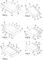
- Number 1 in Figure 1 indicates as a whole a machine for forming a sealed wrapping 2 about a substantially parallelepiped-shaped article 3.
- article 3 comprises two opposite end walls 4 (only one shown in Figure 2 ); two opposite major lateral walls 5 (only one shown in Figure 2 ) crosswise (in particular, perpendicular) to end walls 4; and two opposite minor lateral walls 6 crosswise (in particular, perpendicular) to end walls 4 and major lateral walls 5.
- Machine 1 (in Figure 1 ) forms wrapping 2 from a sheet 7 of wrapping material in the steps shown in Figures 2 to 7 , and as article 3 is fed along a path P.
- Sheet 7 is substantially rectangular and preferably made of airtight, heat-seal material.
- the wrapping 2 formed about article 3 substantially adheres to article 3, and comprises two major lateral portions 8; two minor lateral portions 9 crosswise to major lateral portions 8; and two end portions 10 crosswise to major lateral portions 8 and minor lateral portions 9.
- Wrapping 2 is sealed hermetically about article 3 along three sides by means of respective seals : one at a major lateral portion 8, and the other two at respective end portions 10. Wrapping 2 and article 3 together define a package that may either undergo further processing or be retailed as it is.
- major lateral portions 8 have a larger surface area than minor lateral portions 9. In variations not shown, major lateral portions 8 have substantially the same surface area as minor lateral portions 9.
- machine 1 comprises a conveyor 11 for feeding article 3 to a folding device 12 comprising a push unit 13 and a wrapping wheel 14.
- Wrapping wheel 14 rotates in steps about an axis 15 perpendicular to the Figure 1 plane, and comprises a number of pockets 16 equally spaced about axis 15, and each for receiving a respective article 3 at a loading station 17, and conveying article 3 along a semicircular portion of path P to an unloading station 17'.
- Push unit 13 feeds article 3 in a direction A crosswise (in particular, perpendicular) to axis 15, so article 3 engages sheet 7 and is inserted together with sheet 7 inside respective pocket 16.
- sheet 7 is folded into a U, so that two pairs of flaps 18, at opposite ends of article 3, and a pair of flaps 19, 19' of sheet 7 project from the free sides of article 3.
- the flaps 18, 19 and 19' in each pair face each other and are substantially parallel ( Figure 2 ). Flaps 18 project, parallel to axis 15, from respective end walls 4 of article 3; flaps 19 and 19' project, crosswise to axis 15, from a minor lateral wall 6; and flap 19 is wider than flap 19'.
- Machine 1 ( Figures 1 and 17 ) also comprises a sealing device 20 for superimposing and sealing flaps 19 and 19' to form a substantially tubular partial wrapping 21 having two open ends 22, and a sealing flap 23 projecting outwards crosswise to partial wrapping 21 ( Figure 3 ).
- Partial wrapping 21 comprises major and minor lateral portions 8 and 9, which are connected to one another by respective lateral edges 24; and sealing flap 23 projects outwards from, and extends along, a respective lateral edge 24.
- Sealing device 20 ( Figures 1 and 17 ) comprises a substantially fixed member 25 at loading station 17; and a member 26 which is movable, in a direction crosswise to direction A, between an open position (shown by the continuous line in Figure 17 ) and a closed position (shown by the dash line in Figure 17 ).
- At least one of members 25, 26 is a heat-seal member (i.e. for transferring heat to sheet 7 to seal flaps 19 and 19').
- both members 25, 26 are heat-seal members.
- Sealing device 20 also comprises a heat-seal member 27, downstream from loading station 17 and upstream from unloading station 17', for preferably fluidtight sealing flaps 19 and 19' to each other to form sealing flap 23.
- member 27 oscillates about a respective axis (not shown) substantially parallel to axis 15, to contact flaps 19 and 19' when wheel 14 is stationary.
- machine 1 comprises a number of members 27 arranged successively between loading station 17 and unloading station 17'.
- machine 1 has no member 27, and flaps 19 and 19' are sealed to each other by members 25 and 26 at loading station 17.
- neither of members 25, 26 is a heat-seal member, and flaps 19, 19' are sealed to each other by member/s 27.
- Machine 1 also comprises a folding device 28 for folding sealing flap 23 onto a major lateral portion 8.
- Folding device 28 comprises a known fixed plate (not shown) located along the periphery of wheel 14 to fold sealing flap 23 crosswise (in particular, perpendicularly) to respective major lateral portion 8; and a pusher 29 to feed article 3 in a substantially radial direction with respect to axis 15, so sealing flap 23 is folded onto respective major lateral portion 8 by contrast with a fixed folding member 30.
- Pusher 29 is located at unloading station 17'; and folding device 28 also comprises a heating head 31 located at a stabilizing station 32 along path P, and which is movable crosswise to path P to engage and stabilize sealing flap 23 on major lateral portion 8.
- Machine 1 also comprises a conveyor 33 for feeding article 3 in direction A along a substantially straight portion of path P from stabilizing station 32; through a closing station 34 where open ends 22 of partial wrapping 21 are closed to form sealing flaps 35; to a folding station 36 where sealing flaps 35 are folded.
- Conveyor 33 comprises a belt (shown partly in Figure 1 ) having a work branch 37 and looped about two known pulleys (not shown) rotating about respective axes parallel to axis 15.
- Articles 3 are positioned on conveyor 33 with open ends 22, sealing flap 23, and minor lateral portions 9 crosswise to direction A.
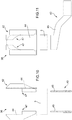
- a retractor 38 deforms a respective open end 22 of partial wrapping 21 to form two facing flaps, and a sealing device 39 grips and preferably fluidtight seals the facing flaps to form respective closed end portion 10 and relative sealing flap 35, which projects from and defines a seal of end portion 10.
- Retractor 38 comprises two arms 40 movable between a closed rest position (shown by the dash line in Figure 8 ), and an open taut position (shown by the continuous line in Figure 8 ).
- Sealing device 39 comprises a gripper unit in turn comprising two heat-seal jaws 41 movable between an open rest position (shown by the dash line in Figure 8 ), and a closed sealing position (shown by the continuous line in Figure 8 ).
- machine 1 also comprises a folding device 42 at folding station 36, to fold sealing flaps 35 onto respective end portions 10.
- Folding device 42 comprises a conveyor 43 for feeding article 3 along a substantially straight portion of path P; and two substantially fixed plates 44 (only one shown) located on opposite sides of path P to fold sealing flaps 35 onto respective end portions 10 (as shown particularly in Figures 12, 13 and 16 ).
- conveyor 43 comprises an elevator 45 for moving article 3 crosswise to major lateral portions 8 in a direction, in particular a substantially vertical direction, crosswise to direction A.
- sealing flaps 35 are of such a length that, once folded, each extends up to a respective edge 24' connecting respective end portion 10 to a major lateral portion 8 (as shown particularly in Figures 6 and 7 ). In variations not shown, sealing flaps 35 are shorter and fall short of respective edges 24'.
- each of sealing flaps 35 comprises two tabs 46 projecting from opposite sides of respective end portion 10.
- Folding device 42 also comprises four flip-over rails 47, each designed so that each tab, as it slides along respective rail 47, is folded roughly 180° onto respective end portion 10 (as shown particularly in the Figure 13 to 15 sequence).
- each rail 47 comprises a first portion 48 for folding respective tab 46 roughly 90° into a position substantially perpendicular to respective end portion 10 ( Figure 14 ); and a second portion 49, after portion 48, for folding tab 46 onto end portion 10 ( Figure 15 ).
- Machine 1 also comprises a conveyor 50, downstream from folding device 42, to feed article 3, crosswise to minor lateral walls 6, along a substantially straight, horizontal portion of path P from folding station 36 to an output station 51.
- Two known heating plates are located on opposite sides of the conveyor to stabilize sealing flaps 35 and tabs 46 on respective end portions 10.
- machine 1 Operation of machine 1 will now be described as of when article 3 is located inside respective pocket 16, and sheet 7 is folded into a U about article 3.
- member 25 folds flap 19 onto flap 19', and wheel 14 moves a first step forward to bring article 3 up to heat-seal member 27, which moves into contact with sealing flap 23.
- said plate (not shown) folds sealing flap 23 by contrast into a position perpendicular to respective major lateral portion 8.
- retractors 38 deform open ends 22; sealing devices 39 form end portions 10 and sealing flaps 35; and conveyor 33 feeds article 3 to folding device 42.
- conveyor 50 feeds article 3 between two known heating plates (not shown) to stabilize sealing flaps 35 and tabs 46 on respective end portions 10 and so obtain package 2.
- sealing flap 23 on major lateral portion 8 provides for particularly good sealing of open ends 22. If sealing flap 23 were to be located on one of minor lateral portions 9, deformation by retractor 38 and sealing by sealing device 39 would be more problematic, on account of the greater thickness of the wrapping material involved, and there would be more risk of sealing flap 23 becoming detached from respective minor lateral portion 9 (especially when deforming open ends 22).
- rails 47 for folding tabs 46 roughly 180° are particularly advantageous in terms of faster production and compactness.
Claims (12)
- Procédé pour former une enveloppe scellée (2) autour d'un article (3), le procédé comprenant les étapes consistant à :plier une feuille (7) de matériau d'emballage autour de l'article (3), de sorte que la feuille (7) pliée a une paire de rabats en saillie se faisant face, sensiblement parallèles (19, 19') ;superposer et sceller la paire de rabats (19, 19') pour former une enveloppe partielle (21) sensiblement tubulaire ayant deux extrémités ouvertes (22), un premier rabat d'étanchéité (23) faisant saillie vers l'extérieur transversalement par rapport à l'enveloppe partielle (21) ;plier le premier rabat d'étanchéité (23) sur une surface externe de l'enveloppe partielle (21) ;saisir et sceller successivement les extrémités ouvertes (22) de l'enveloppe partielle (21) ;déformer au moins l'une des extrémités ouvertes (22) de l'enveloppe partielle (21) au moyen d'un rétracteur (38), afin de former deux rabats en vis-à-vis ; et saisir et sceller les rabats en vis-à-vis afin de former une partie d'extrémité (10) fermée respective et un second rabat d'étanchéité (35) qui fait saillie à partir de la partie d'extrémité (10) et définit un joint d'étanchéité de la partie d'extrémité (10) ;plier le second rabat d'étanchéité (35) sur la partie d'extrémité (10) de sorte que deux languettes (46) du second rabat d'étanchéité (35) font saillie latéralement à partir de la partie d'extrémité (10) et sur les côtés opposés de la partie d'extrémité (10) ; etplier chaque languette (46) sur la partie d'extrémité (10) ;dans lequel la feuille (7) du matériau d'emballage est pliée et scellée autour de l'article (3), de sorte que l'enveloppe partielle (21) comprend deux parties latérales majeures (8) sur les côtés opposés de l'article (3), et deux parties latérales mineures (9) qui sont positionnées sur les côtés opposés de l'article (3), sont transversales par rapport aux parties latérales majeures (8) et sont raccordées aux parties latérales majeures (8) par des bords latéraux (24) respectifs ; le premier rabat d'étanchéité (23) s'étendant sensiblement le long d'un bord latéral (24) respectif, et étant plié sur l'une des parties latérales majeures (8) de l'enveloppe partielle (21) ; et les extrémités ouvertes (22) de l'enveloppe partielle (21) étant fermées et scellées pour les saisir afin de former les deux seconds rabats d'étanchéité (35) sensiblement transversalement par rapport au premier rabat d'étanchéité (23) et aux parties latérales mineures (9) ;dans lequel les languettes (46) sont pliées sur la partie d'extrémité lorsque la feuille (7), pliée autour de l'article (3), est alimentée dans une direction sensiblement parallèle à ladite partie d'extrémité (10) et auxdites languettes (46), et en particulier transversalement par rapport aux parties latérales majeures (8).
- Procédé selon la revendication 1, dans lequel un rail (47) comprend une première partie (48) qui plie une languette (46) respective approximativement à 90° dans une position sensiblement perpendiculaire à une partie d'extrémité (10) respective ; et une seconde partie (49), après la partie (48), pour plier la languette (46) sur la partie d'extrémité (10) .
- Procédé selon la revendication 1 ou 2, dans lequel un dispositif de pliage (42) pour plier les languettes comprend quatre rails rabattables (47), chacun conçu de sorte que chaque languette, lorsqu'elle coulisse le long du rail (47) respectif, est pliée approximativement à 180° sur la partie d'extrémité (10) respective.
- Procédé selon l'une des revendications précédentes, dans lequel le premier rabat d'étanchéité (23) est tout d'abord plié pour faire saillie sensiblement perpendiculairement à ladite partie latérale majeure (8) relative, est maintenue dans cette position et est ensuite pliée sur la partie latérale majeure (8) relative.
- Procédé selon l'une des revendications précédentes, dans lequel l'article (3) comprend deux parois d'extrémité (4) sensiblement opposées ; deux parois latérales majeures (5) sensiblement opposées transversalement par rapport aux parois d'extrémité (4), et deux parois latérales mineures (6) transversalement par rapport aux parois d'extrémité (4) et aux parois latérales majeures (5) ;
la feuille (7) étant pliée et scellée de sorte que chaque partie latérale majeure (8) de l'enveloppe partielle (21) est positionnée au niveau d'une paroi latérale majeure (5) respective, et chaque partie latérale mineure (9) de l'enveloppe partielle est positionnée au niveau d'une paroi latérale mineure (6) respective. - Procédé selon l'une des revendications précédentes, dans lequel les languettes (46) sont sensiblement pliées approximativement à 180° sur la partie d'extrémité (10), en coulissant chacune le long d'un rail (47) respectif d'un dispositif de pliage (42).
- Machine pour former une enveloppe scellée (2) autour d'un article (3), la machine (1) comprenant :un premier dispositif de pliage (12) pour plier une feuille (7) de matériau d'emballage en U autour de l'article (3), de sorte que la feuille pliée (7) a une paire de rabats en saillie, en vis-à-vis, sensiblement parallèles (18, 19, 19') sur chaque côté libre de l'article (3) ;un premier dispositif d'étanchéité (20) pour superposer et sceller les rabats (19, 19') en une paire afin de former une enveloppe partielle (21) sensiblement tubulaire ayant deux extrémités ouvertes (22), et un premier rabat d'étanchéité (23) faisant saillie vers l'extérieur transversalement par rapport à l'enveloppe partielle (21) ;un deuxième dispositif de pliage (28) pour plier le premier rabat d'étanchéité (23) sur une surface externe de la feuille (7) ; etdeux seconds dispositifs d'étanchéité (39) pour sceller les extrémités ouvertes (22) de l'enveloppe partielle (21) ;au moins un rétracteur (38) pour déformer au moins l'une des extrémités ouvertes (22) de l'enveloppe partielle (21) afin de définir deux rabats en vis-à-vis ; chaque second dispositif d'étanchéité (39) saisissant et scellant lesdits rabats en vis-à-vis afin de former une partie d'extrémité (10) fermée respective et un second rabat d'étanchéité (35), qui fait saillie de la partie d'extrémité (10) et définit un joint d'étanchéité de la partie d'extrémité (10) ; etun troisième dispositif de pliage (42) pour plier le second rabat d'étanchéité (35) sur la partie d'extrémité (10) relative de sorte que deux languettes (46) du second rabat d'étanchéité (35) font saillie latéralement sur les côtés opposés de la partie d'extrémité (10) ; le troisième dispositif de pliage (42) pliant également chaque languette (46) sur la partie d'extrémité (10) ;dans lequel le premier dispositif de pliage (12) et le premier dispositif d'étanchéité (20) plient et scellent la feuille (7) autour de l'article (3) de sorte que l'enveloppe partielle (21) comprend deux parties latérales majeures (8) sur les côtés opposés de l'article (3) ; et deux partie latérales mineures (9) qui sont positionnées sur les côtés opposés de l'article (3), sont transversales par rapport aux parties latérales majeures (8), et sont raccordées aux parties latérales majeures (8) par des bords latéraux (24) respectifs ; le premier rabat d'étanchéité (23) s'étendant le long d'un bord latéral (24) respectif ; le second dispositif de pliage (28) pliant le premier rabat d'étanchéité sur l'une des parties latérales majeures (8) de l'enveloppe partielle (21) ; et chaque second dispositif d'étanchéité (39) comprenant au moins une unité de préhension pour fermer et sceller les extrémités ouvertes (22) de l'enveloppe partielle (21) afin de former deux second rabats d'étanchéité (35) transversalement par rapport au premier rabat d'étanchéité (23) et aux parties latérales mineures (9) ;dans lequel les languettes (46) sont pliées sur la partie d'extrémité lorsque la feuille (7), pliée autour de l'article (3), est alimentée dans une direction sensiblement parallèle à ladite partie d'extrémité (10) et auxdites languettes (46), et en particulier transversalement par rapport aux parties latérales majeures (8).
- Machine selon la revendication 7, et comprenant un rail (47) qui comprend une première partie (48) pour plier une languette (46) respective approximativement à 90° dans une position sensiblement perpendiculaire à la partie d'extrémité (10) respective ; et une seconde partie (49), après la partie (48), pour plier la languette (46) sur la partie d'extrémité (10).
- Machine selon la revendication 7 ou 8, dans laquelle l'unité de préhension comprend deux mâchoires de thermosoudage (41).
- Machine selon l'une des revendications 7 à 9, dans laquelle le premier dispositif de pliage (12) comprend au moins une poche (16) ; et une unité de poussée (13) pour alimenter l'article (3), transversalement par rapport à la feuille (7), dans la poche (16), de sorte que la feuille (7) est poussée dans la poche (16) par l'article (3) et pliée en U autour de l'article (3) .
- Machine selon la revendication 10, et comprenant un transporteur (43) pour alimenter l'article (3), dans une direction transversale par rapport au second rabat d'étanchéité (35) faisant saillie de la partie d'extrémité (10), le long d'une partie d'une trajectoire d'alimentation (P), laquelle partie est positionnée en aval des seconds dispositifs d'étanchéité (39) et au niveau du troisième dispositif de pliage (42) ; le troisième dispositif de pliage (42) comprenant au moins un élément (44) sensiblement fixe qui intercepte le second rabat d'étanchéité (35) pour plier le second rabat d'étanchéité (35) sur la partie d'extrémité (10) .
- Machine selon l'une des revendications 7 à 11, dans laquelle le troisième dispositif de pliage (42) comprend au moins deux rails (47) conçus de sorte que chaque languette (46), lorsqu'elle coulisse le long du rail (47) relatif, est pliée approximativement à 180° sur la partie d'extrémité (10) relative.
Applications Claiming Priority (2)
| Application Number | Priority Date | Filing Date | Title |
|---|---|---|---|
| IT000254A ITBO20080254A1 (it) | 2008-04-23 | 2008-04-23 | Metodo e macchina per la realizzazione di un involucro sigillato attorno ad un articolo e confezione cosi ottenuta. |
| PCT/EP2009/054760 WO2009130227A1 (fr) | 2008-04-23 | 2009-04-21 | Procédé et machine de formation d’une enveloppe scellée autour d’un article, et emballage ainsi réalisé |
Publications (2)
| Publication Number | Publication Date |
|---|---|
| EP2282943A1 EP2282943A1 (fr) | 2011-02-16 |
| EP2282943B1 true EP2282943B1 (fr) | 2020-01-08 |
Family
ID=40296668
Family Applications (1)
| Application Number | Title | Priority Date | Filing Date |
|---|---|---|---|
| EP09733773.7A Active EP2282943B1 (fr) | 2008-04-23 | 2009-04-21 | Procédé et machine de formation d'une enveloppe scellée autour d'un article |
Country Status (8)
| Country | Link |
|---|---|
| US (1) | US20110120903A1 (fr) |
| EP (1) | EP2282943B1 (fr) |
| CN (1) | CN102066201A (fr) |
| BR (1) | BRPI0907323B1 (fr) |
| ES (1) | ES2776468T3 (fr) |
| IT (1) | ITBO20080254A1 (fr) |
| RU (1) | RU2493061C2 (fr) |
| WO (1) | WO2009130227A1 (fr) |
Families Citing this family (10)
| Publication number | Priority date | Publication date | Assignee | Title |
|---|---|---|---|---|
| IT1394365B1 (it) * | 2009-05-26 | 2012-06-15 | Gd Spa | Metodo e unità di incarto per ripiegare un foglio di incarto attorno ad un gruppo di sigarette. |
| DE102009060134A1 (de) * | 2009-12-09 | 2011-06-16 | Focke & Co.(Gmbh & Co. Kg) | Packungen insbesondere für Zigaretten sowie Verfahren und Vorrichtung zum Herstellen derselben |
| US20140013715A1 (en) * | 2011-03-23 | 2014-01-16 | Robert Bosch Gmbh | Method for packaging products, particularly portions of chocolate or the like, and facility for implementing the method |
| ITBO20110717A1 (it) * | 2011-12-15 | 2013-06-16 | So Te Ma Pack S R L | Dispositivo per realizzare una pinna longitudinale in un corrispondente involucro di avvolgimento di un prodotto. |
| ITBO20110718A1 (it) * | 2011-12-15 | 2013-06-16 | So Te Ma Pack S R L | Apparecchiatura per realizzare una rispettiva confezione. |
| EP2791014A2 (fr) * | 2011-12-15 | 2014-10-22 | So.Te.Ma. Pack S.r.l. | Appareil permettant de confectionner un paquet |
| ITBO20110719A1 (it) * | 2011-12-15 | 2013-06-16 | So Te Ma Pack S R L | Dispositivo per realizzare una pinna trasversale estrema in un involucro di avvolgimento di un prodotto. |
| PL234442B1 (pl) * | 2014-03-14 | 2020-02-28 | Gd Spa | Opakowanie zawierające paczkę wyrobów tytoniowych oraz owijkę wierzchnią otaczającą paczkę wyrobów tytoniowych |
| DE112015001243T5 (de) * | 2014-03-14 | 2017-01-19 | G. D Societa' Per Azioni | Verpackungsverfahren und Verpackungseinheit zur Herstellung einer versiegelten Innenverpackung |
| IT201700093993A1 (it) | 2017-08-17 | 2019-02-17 | Gima Tt S P A | Metodo per realizzare un incarto ermetico ed incarto ermetico cosi' realizzato |
Citations (3)
| Publication number | Priority date | Publication date | Assignee | Title |
|---|---|---|---|---|
| US2262774A (en) * | 1937-07-07 | 1941-11-18 | American Mach & Foundry | Packaging cigarettes and the like |
| US4044528A (en) * | 1974-09-03 | 1977-08-30 | American Brands, Inc. | Method and apparatus for forming sealed packages |
| JP3193882B2 (ja) * | 1997-02-13 | 2001-07-30 | テンチ機械株式会社 | 包装装置 |
Family Cites Families (22)
| Publication number | Priority date | Publication date | Assignee | Title |
|---|---|---|---|---|
| US2152323A (en) * | 1937-03-18 | 1939-03-28 | Humoco Corp | Container |
| US2196666A (en) * | 1938-11-21 | 1940-04-09 | Humoco Corp | Method and means of making containers |
| US2374793A (en) * | 1940-06-20 | 1945-05-01 | Harry F Waters | Method of fluid-tight packaging |
| DE1105335B (de) * | 1958-02-26 | 1961-04-20 | Hesser Ag Maschf | Einwickelmaschine |
| US2966832A (en) * | 1958-08-20 | 1961-01-03 | Pneumatic Scale Corp | Container forming machine |
| CH376417A (de) * | 1960-04-01 | 1964-03-31 | Sig Schweiz Industrieges | Vorrichtung zum Fertigfalten einer Packung |
| US3264115A (en) * | 1962-07-10 | 1966-08-02 | Harry E Davis | Safety lollipop |
| US3272152A (en) * | 1963-08-30 | 1966-09-13 | Shafter L Williams | Apparatus for making and wrapping soft-center candy suckers |
| US3899865A (en) * | 1973-10-03 | 1975-08-19 | Haensel Otto Gmbh | Wrapping apparatus |
| US4024692A (en) * | 1976-02-18 | 1977-05-24 | William E. Young | Apparatus and method of packaging large items |
| IT1171929B (it) * | 1983-06-14 | 1987-06-10 | Gd Spa | Metodo per incartare gruppi di prodotti impilati per la formazione di pacchetti sigillati |
| IT1232103B (it) * | 1989-05-24 | 1992-01-23 | Ferrero Spa | Macchina incartatrice,particolarmente per caramelle e simili prodotti alimentari |
| US5241807A (en) * | 1992-02-26 | 1993-09-07 | Quick Howard E | Method and apparatus for wrapping lollipops and similar articles |
| US5450706A (en) * | 1993-05-24 | 1995-09-19 | Latini Machine Company, Inc. | Single twist bunch wrapping machine |
| JP2621016B2 (ja) * | 1993-09-06 | 1997-06-18 | テンチ機械株式会社 | ひねり包装機 |
| JP2936458B2 (ja) * | 1995-10-31 | 1999-08-23 | 株式会社フジキカイ | 粒状物品の集合包装方法および装置 |
| IT1286281B1 (it) * | 1996-10-31 | 1998-07-08 | Bl Macchine Automatiche | Metodo per la registrazione di sacchi di materiale plastico e sacco cosi' ottenuto |
| US6860089B2 (en) * | 2002-04-10 | 2005-03-01 | Detail Machine Company | Pillow pack wrapping technique and related apparatus |
| BR0309351B1 (pt) * | 2002-04-18 | 2012-09-18 | máquina para embalar produtos. | |
| ITBO20020222A1 (it) * | 2002-04-23 | 2003-10-23 | Azionaria Costruzioni Acma Spa | Metodo e ruota di incarto per il condizionamento di pile di prodotti |
| ITBO20030093A1 (it) * | 2003-02-25 | 2004-08-26 | Azionario Costruzioni Macchine Auto Matiche A C Ma | Metodo e dispositivo per incartare gruppi di prodotti |
| ITBO20050392A1 (it) * | 2005-06-08 | 2005-09-07 | Azionaria Costruzioni Acma Spa | Metodo e macchina per la realizzazione di un involucro sigillato attorno ad un prodotto ed involucro con il suddetto metodo |
-
2008
- 2008-04-23 IT IT000254A patent/ITBO20080254A1/it unknown
-
2009
- 2009-04-21 EP EP09733773.7A patent/EP2282943B1/fr active Active
- 2009-04-21 BR BRPI0907323A patent/BRPI0907323B1/pt active IP Right Grant
- 2009-04-21 CN CN2009801226074A patent/CN102066201A/zh active Pending
- 2009-04-21 ES ES09733773T patent/ES2776468T3/es active Active
- 2009-04-21 WO PCT/EP2009/054760 patent/WO2009130227A1/fr active Application Filing
- 2009-04-21 RU RU2010147647/13A patent/RU2493061C2/ru active
- 2009-04-21 US US12/989,133 patent/US20110120903A1/en not_active Abandoned
Patent Citations (3)
| Publication number | Priority date | Publication date | Assignee | Title |
|---|---|---|---|---|
| US2262774A (en) * | 1937-07-07 | 1941-11-18 | American Mach & Foundry | Packaging cigarettes and the like |
| US4044528A (en) * | 1974-09-03 | 1977-08-30 | American Brands, Inc. | Method and apparatus for forming sealed packages |
| JP3193882B2 (ja) * | 1997-02-13 | 2001-07-30 | テンチ機械株式会社 | 包装装置 |
Also Published As
| Publication number | Publication date |
|---|---|
| RU2010147647A (ru) | 2012-05-27 |
| WO2009130227A1 (fr) | 2009-10-29 |
| ES2776468T3 (es) | 2020-07-30 |
| US20110120903A1 (en) | 2011-05-26 |
| BRPI0907323B1 (pt) | 2020-04-28 |
| ITBO20080254A1 (it) | 2009-10-24 |
| RU2493061C2 (ru) | 2013-09-20 |
| CN102066201A (zh) | 2011-05-18 |
| EP2282943A1 (fr) | 2011-02-16 |
| BRPI0907323A2 (pt) | 2016-07-26 |
Similar Documents
| Publication | Publication Date | Title |
|---|---|---|
| EP2282943B1 (fr) | Procédé et machine de formation d'une enveloppe scellée autour d'un article | |
| US6606840B2 (en) | Process and apparatus for producing (cigarette) packs | |
| EP1899225B1 (fr) | Procédé et machine pour réaliser un emballage étanche autour d un produit et emballage obtenu au moyen dudit procédé | |
| CN108472910B (zh) | 装盒机的操作组,装盒机以及形成纸盒的方法 | |
| EP1452448B1 (fr) | Procédé pour emballer des cigarettes dans des paquets mous | |
| US6904738B2 (en) | Method and unit for packing groups of products | |
| KR101913231B1 (ko) | 포장방법 및 포장 시스템 | |
| ITBO20060374A1 (it) | Metodo e dispositivo per l'incarto di prodotti | |
| WO2007014917A1 (fr) | Procede et machine servant a former des groupes de produits et a emballer chaque groupe | |
| US10689142B2 (en) | Apparatus to form edges in a package made of flexible material | |
| KR101911857B1 (ko) | 리테이너에 수용된 포대의 입구의 밀봉방법 및 그 밀봉 시스템 | |
| CN114401898B (zh) | 用于通过折叠形成容器的装置和方法 | |
| IT201800010102A1 (it) | Macchina e metodo per il confezionamento ermetico di prodotti alimentari | |
| JP5158822B2 (ja) | 袋シール装置 | |
| EP0112605A2 (fr) | Emballage | |
| JP2019099171A (ja) | 包装装置 | |
| JP6329098B2 (ja) | 二連袋を用いた袋詰め包装方法及び装置 | |
| US11299299B2 (en) | Machine and process for making packages containing liquid or creamy products | |
| EP0270528B1 (fr) | Procede et appareil de montage, de remplissage et de fermeture d'une ebauche d'emballage, et ebauche d'emballage | |
| CN114555473B (zh) | 自动填充包装装置 | |
| EP0761537A1 (fr) | Procédé et unité pour l'emballage d'objets | |
| JP2764462B2 (ja) | 袋詰め封止装置 | |
| GB1196734A (en) | Method and Apparatus for Wrapping Block-Like Articles. | |
| JP6706565B2 (ja) | 包装機および包装体の耳折り方法 | |
| WO2023126765A2 (fr) | Unité et procédé d'emballage d'articles dans des boîtes |
Legal Events
| Date | Code | Title | Description |
|---|---|---|---|
| PUAI | Public reference made under article 153(3) epc to a published international application that has entered the european phase |
Free format text: ORIGINAL CODE: 0009012 |
|
| 17P | Request for examination filed |
Effective date: 20101018 |
|
| AK | Designated contracting states |
Kind code of ref document: A1 Designated state(s): AT BE BG CH CY CZ DE DK EE ES FI FR GB GR HR HU IE IS IT LI LT LU LV MC MK MT NL NO PL PT RO SE SI SK TR |
|
| AX | Request for extension of the european patent |
Extension state: AL BA RS |
|
| RIN1 | Information on inventor provided before grant (corrected) |
Inventor name: CARRARA, MARCO Inventor name: CIVOLANI, DANIELE |
|
| DAX | Request for extension of the european patent (deleted) | ||
| TPAC | Observations filed by third parties |
Free format text: ORIGINAL CODE: EPIDOSNTIPA |
|
| 17Q | First examination report despatched |
Effective date: 20160223 |
|
| STAA | Information on the status of an ep patent application or granted ep patent |
Free format text: STATUS: EXAMINATION IS IN PROGRESS |
|
| GRAP | Despatch of communication of intention to grant a patent |
Free format text: ORIGINAL CODE: EPIDOSNIGR1 |
|
| STAA | Information on the status of an ep patent application or granted ep patent |
Free format text: STATUS: GRANT OF PATENT IS INTENDED |
|
| INTG | Intention to grant announced |
Effective date: 20190902 |
|
| GRAS | Grant fee paid |
Free format text: ORIGINAL CODE: EPIDOSNIGR3 |
|
| GRAA | (expected) grant |
Free format text: ORIGINAL CODE: 0009210 |
|
| STAA | Information on the status of an ep patent application or granted ep patent |
Free format text: STATUS: THE PATENT HAS BEEN GRANTED |
|
| AK | Designated contracting states |
Kind code of ref document: B1 Designated state(s): AT BE BG CH CY CZ DE DK EE ES FI FR GB GR HR HU IE IS IT LI LT LU LV MC MK MT NL NO PL PT RO SE SI SK TR |
|
| REG | Reference to a national code |
Ref country code: GB Ref legal event code: FG4D |
|
| REG | Reference to a national code |
Ref country code: CH Ref legal event code: EP |
|
| REG | Reference to a national code |
Ref country code: DE Ref legal event code: R096 Ref document number: 602009060944 Country of ref document: DE |
|
| REG | Reference to a national code |
Ref country code: IE Ref legal event code: FG4D |
|
| REG | Reference to a national code |
Ref country code: AT Ref legal event code: REF Ref document number: 1222405 Country of ref document: AT Kind code of ref document: T Effective date: 20200215 |
|
| REG | Reference to a national code |
Ref country code: CH Ref legal event code: NV Representative=s name: MOINAS AND SAVOYE SARL, CH |
|
| REG | Reference to a national code |
Ref country code: NL Ref legal event code: MP Effective date: 20200108 |
|
| REG | Reference to a national code |
Ref country code: LT Ref legal event code: MG4D |
|
| REG | Reference to a national code |
Ref country code: ES Ref legal event code: FG2A Ref document number: 2776468 Country of ref document: ES Kind code of ref document: T3 Effective date: 20200730 |
|
| PG25 | Lapsed in a contracting state [announced via postgrant information from national office to epo] |
Ref country code: NO Free format text: LAPSE BECAUSE OF FAILURE TO SUBMIT A TRANSLATION OF THE DESCRIPTION OR TO PAY THE FEE WITHIN THE PRESCRIBED TIME-LIMIT Effective date: 20200408 Ref country code: FI Free format text: LAPSE BECAUSE OF FAILURE TO SUBMIT A TRANSLATION OF THE DESCRIPTION OR TO PAY THE FEE WITHIN THE PRESCRIBED TIME-LIMIT Effective date: 20200108 Ref country code: LT Free format text: LAPSE BECAUSE OF FAILURE TO SUBMIT A TRANSLATION OF THE DESCRIPTION OR TO PAY THE FEE WITHIN THE PRESCRIBED TIME-LIMIT Effective date: 20200108 Ref country code: NL Free format text: LAPSE BECAUSE OF FAILURE TO SUBMIT A TRANSLATION OF THE DESCRIPTION OR TO PAY THE FEE WITHIN THE PRESCRIBED TIME-LIMIT Effective date: 20200108 Ref country code: PT Free format text: LAPSE BECAUSE OF FAILURE TO SUBMIT A TRANSLATION OF THE DESCRIPTION OR TO PAY THE FEE WITHIN THE PRESCRIBED TIME-LIMIT Effective date: 20200531 |
|
| PGFP | Annual fee paid to national office [announced via postgrant information from national office to epo] |
Ref country code: CH Payment date: 20200504 Year of fee payment: 12 Ref country code: FR Payment date: 20200427 Year of fee payment: 12 Ref country code: ES Payment date: 20200504 Year of fee payment: 12 |
|
| PG25 | Lapsed in a contracting state [announced via postgrant information from national office to epo] |
Ref country code: GR Free format text: LAPSE BECAUSE OF FAILURE TO SUBMIT A TRANSLATION OF THE DESCRIPTION OR TO PAY THE FEE WITHIN THE PRESCRIBED TIME-LIMIT Effective date: 20200409 Ref country code: HR Free format text: LAPSE BECAUSE OF FAILURE TO SUBMIT A TRANSLATION OF THE DESCRIPTION OR TO PAY THE FEE WITHIN THE PRESCRIBED TIME-LIMIT Effective date: 20200108 Ref country code: LV Free format text: LAPSE BECAUSE OF FAILURE TO SUBMIT A TRANSLATION OF THE DESCRIPTION OR TO PAY THE FEE WITHIN THE PRESCRIBED TIME-LIMIT Effective date: 20200108 Ref country code: SE Free format text: LAPSE BECAUSE OF FAILURE TO SUBMIT A TRANSLATION OF THE DESCRIPTION OR TO PAY THE FEE WITHIN THE PRESCRIBED TIME-LIMIT Effective date: 20200108 Ref country code: BG Free format text: LAPSE BECAUSE OF FAILURE TO SUBMIT A TRANSLATION OF THE DESCRIPTION OR TO PAY THE FEE WITHIN THE PRESCRIBED TIME-LIMIT Effective date: 20200408 Ref country code: IS Free format text: LAPSE BECAUSE OF FAILURE TO SUBMIT A TRANSLATION OF THE DESCRIPTION OR TO PAY THE FEE WITHIN THE PRESCRIBED TIME-LIMIT Effective date: 20200508 |
|
| PGFP | Annual fee paid to national office [announced via postgrant information from national office to epo] |
Ref country code: GB Payment date: 20200427 Year of fee payment: 12 |
|
| REG | Reference to a national code |
Ref country code: DE Ref legal event code: R097 Ref document number: 602009060944 Country of ref document: DE |
|
| PG25 | Lapsed in a contracting state [announced via postgrant information from national office to epo] |
Ref country code: CZ Free format text: LAPSE BECAUSE OF FAILURE TO SUBMIT A TRANSLATION OF THE DESCRIPTION OR TO PAY THE FEE WITHIN THE PRESCRIBED TIME-LIMIT Effective date: 20200108 Ref country code: SK Free format text: LAPSE BECAUSE OF FAILURE TO SUBMIT A TRANSLATION OF THE DESCRIPTION OR TO PAY THE FEE WITHIN THE PRESCRIBED TIME-LIMIT Effective date: 20200108 Ref country code: RO Free format text: LAPSE BECAUSE OF FAILURE TO SUBMIT A TRANSLATION OF THE DESCRIPTION OR TO PAY THE FEE WITHIN THE PRESCRIBED TIME-LIMIT Effective date: 20200108 Ref country code: EE Free format text: LAPSE BECAUSE OF FAILURE TO SUBMIT A TRANSLATION OF THE DESCRIPTION OR TO PAY THE FEE WITHIN THE PRESCRIBED TIME-LIMIT Effective date: 20200108 Ref country code: DK Free format text: LAPSE BECAUSE OF FAILURE TO SUBMIT A TRANSLATION OF THE DESCRIPTION OR TO PAY THE FEE WITHIN THE PRESCRIBED TIME-LIMIT Effective date: 20200108 |
|
| PLBE | No opposition filed within time limit |
Free format text: ORIGINAL CODE: 0009261 |
|
| STAA | Information on the status of an ep patent application or granted ep patent |
Free format text: STATUS: NO OPPOSITION FILED WITHIN TIME LIMIT |
|
| REG | Reference to a national code |
Ref country code: AT Ref legal event code: MK05 Ref document number: 1222405 Country of ref document: AT Kind code of ref document: T Effective date: 20200108 |
|
| PG25 | Lapsed in a contracting state [announced via postgrant information from national office to epo] |
Ref country code: MC Free format text: LAPSE BECAUSE OF FAILURE TO SUBMIT A TRANSLATION OF THE DESCRIPTION OR TO PAY THE FEE WITHIN THE PRESCRIBED TIME-LIMIT Effective date: 20200108 |
|
| 26N | No opposition filed |
Effective date: 20201009 |
|
| PG25 | Lapsed in a contracting state [announced via postgrant information from national office to epo] |
Ref country code: LU Free format text: LAPSE BECAUSE OF NON-PAYMENT OF DUE FEES Effective date: 20200421 Ref country code: AT Free format text: LAPSE BECAUSE OF FAILURE TO SUBMIT A TRANSLATION OF THE DESCRIPTION OR TO PAY THE FEE WITHIN THE PRESCRIBED TIME-LIMIT Effective date: 20200108 |
|
| REG | Reference to a national code |
Ref country code: BE Ref legal event code: MM Effective date: 20200430 |
|
| PG25 | Lapsed in a contracting state [announced via postgrant information from national office to epo] |
Ref country code: SI Free format text: LAPSE BECAUSE OF FAILURE TO SUBMIT A TRANSLATION OF THE DESCRIPTION OR TO PAY THE FEE WITHIN THE PRESCRIBED TIME-LIMIT Effective date: 20200108 Ref country code: BE Free format text: LAPSE BECAUSE OF NON-PAYMENT OF DUE FEES Effective date: 20200430 Ref country code: PL Free format text: LAPSE BECAUSE OF FAILURE TO SUBMIT A TRANSLATION OF THE DESCRIPTION OR TO PAY THE FEE WITHIN THE PRESCRIBED TIME-LIMIT Effective date: 20200108 |
|
| PG25 | Lapsed in a contracting state [announced via postgrant information from national office to epo] |
Ref country code: IE Free format text: LAPSE BECAUSE OF NON-PAYMENT OF DUE FEES Effective date: 20200421 |
|
| GBPC | Gb: european patent ceased through non-payment of renewal fee |
Effective date: 20210421 |
|
| PG25 | Lapsed in a contracting state [announced via postgrant information from national office to epo] |
Ref country code: CH Free format text: LAPSE BECAUSE OF NON-PAYMENT OF DUE FEES Effective date: 20210430 Ref country code: LI Free format text: LAPSE BECAUSE OF NON-PAYMENT OF DUE FEES Effective date: 20210430 Ref country code: FR Free format text: LAPSE BECAUSE OF NON-PAYMENT OF DUE FEES Effective date: 20210430 Ref country code: GB Free format text: LAPSE BECAUSE OF NON-PAYMENT OF DUE FEES Effective date: 20210421 |
|
| PG25 | Lapsed in a contracting state [announced via postgrant information from national office to epo] |
Ref country code: TR Free format text: LAPSE BECAUSE OF FAILURE TO SUBMIT A TRANSLATION OF THE DESCRIPTION OR TO PAY THE FEE WITHIN THE PRESCRIBED TIME-LIMIT Effective date: 20200108 Ref country code: MT Free format text: LAPSE BECAUSE OF FAILURE TO SUBMIT A TRANSLATION OF THE DESCRIPTION OR TO PAY THE FEE WITHIN THE PRESCRIBED TIME-LIMIT Effective date: 20200108 Ref country code: CY Free format text: LAPSE BECAUSE OF FAILURE TO SUBMIT A TRANSLATION OF THE DESCRIPTION OR TO PAY THE FEE WITHIN THE PRESCRIBED TIME-LIMIT Effective date: 20200108 |
|
| PG25 | Lapsed in a contracting state [announced via postgrant information from national office to epo] |
Ref country code: MK Free format text: LAPSE BECAUSE OF FAILURE TO SUBMIT A TRANSLATION OF THE DESCRIPTION OR TO PAY THE FEE WITHIN THE PRESCRIBED TIME-LIMIT Effective date: 20200108 |
|
| REG | Reference to a national code |
Ref country code: ES Ref legal event code: FD2A Effective date: 20220705 |
|
| PG25 | Lapsed in a contracting state [announced via postgrant information from national office to epo] |
Ref country code: ES Free format text: LAPSE BECAUSE OF NON-PAYMENT OF DUE FEES Effective date: 20210422 |
|
| P01 | Opt-out of the competence of the unified patent court (upc) registered |
Effective date: 20230529 |
|
| PGFP | Annual fee paid to national office [announced via postgrant information from national office to epo] |
Ref country code: IT Payment date: 20230419 Year of fee payment: 15 Ref country code: DE Payment date: 20230427 Year of fee payment: 15 |