EP2282917B1 - Wischblatt sowie wischarm - Google Patents
Wischblatt sowie wischarm Download PDFInfo
- Publication number
- EP2282917B1 EP2282917B1 EP09761480.4A EP09761480A EP2282917B1 EP 2282917 B1 EP2282917 B1 EP 2282917B1 EP 09761480 A EP09761480 A EP 09761480A EP 2282917 B1 EP2282917 B1 EP 2282917B1
- Authority
- EP
- European Patent Office
- Prior art keywords
- wiper blade
- adapter
- wiper
- axis
- wiper arm
- Prior art date
- Legal status (The legal status is an assumption and is not a legal conclusion. Google has not performed a legal analysis and makes no representation as to the accuracy of the status listed.)
- Active
Links
Images


Classifications
-
- B—PERFORMING OPERATIONS; TRANSPORTING
- B60—VEHICLES IN GENERAL
- B60S—SERVICING, CLEANING, REPAIRING, SUPPORTING, LIFTING, OR MANOEUVRING OF VEHICLES, NOT OTHERWISE PROVIDED FOR
- B60S1/00—Cleaning of vehicles
- B60S1/02—Cleaning windscreens, windows or optical devices
- B60S1/04—Wipers or the like, e.g. scrapers
- B60S1/32—Wipers or the like, e.g. scrapers characterised by constructional features of wiper blade arms or blades
- B60S1/38—Wiper blades
- B60S1/3803—Wiper blades heated wiper blades
- B60S1/3805—Wiper blades heated wiper blades electrically
-
- B—PERFORMING OPERATIONS; TRANSPORTING
- B60—VEHICLES IN GENERAL
- B60S—SERVICING, CLEANING, REPAIRING, SUPPORTING, LIFTING, OR MANOEUVRING OF VEHICLES, NOT OTHERWISE PROVIDED FOR
- B60S1/00—Cleaning of vehicles
- B60S1/02—Cleaning windscreens, windows or optical devices
- B60S1/04—Wipers or the like, e.g. scrapers
- B60S1/32—Wipers or the like, e.g. scrapers characterised by constructional features of wiper blade arms or blades
- B60S1/38—Wiper blades
- B60S1/3806—Means, or measures taken, for influencing the aerodynamic quality of the wiper blades
- B60S1/381—Spoilers mounted on the squeegee or on the vertebra
-
- B—PERFORMING OPERATIONS; TRANSPORTING
- B60—VEHICLES IN GENERAL
- B60S—SERVICING, CLEANING, REPAIRING, SUPPORTING, LIFTING, OR MANOEUVRING OF VEHICLES, NOT OTHERWISE PROVIDED FOR
- B60S1/00—Cleaning of vehicles
- B60S1/02—Cleaning windscreens, windows or optical devices
- B60S1/04—Wipers or the like, e.g. scrapers
- B60S1/32—Wipers or the like, e.g. scrapers characterised by constructional features of wiper blade arms or blades
- B60S1/38—Wiper blades
- B60S1/3848—Flat-type wiper blade, i.e. without harness
- B60S1/3849—Connectors therefor; Connection to wiper arm; Attached to blade
- B60S1/3851—Mounting of connector to blade assembly
- B60S1/3856—Gripping the blade
-
- B—PERFORMING OPERATIONS; TRANSPORTING
- B60—VEHICLES IN GENERAL
- B60S—SERVICING, CLEANING, REPAIRING, SUPPORTING, LIFTING, OR MANOEUVRING OF VEHICLES, NOT OTHERWISE PROVIDED FOR
- B60S1/00—Cleaning of vehicles
- B60S1/02—Cleaning windscreens, windows or optical devices
- B60S1/04—Wipers or the like, e.g. scrapers
- B60S1/32—Wipers or the like, e.g. scrapers characterised by constructional features of wiper blade arms or blades
- B60S1/38—Wiper blades
- B60S1/3848—Flat-type wiper blade, i.e. without harness
- B60S1/3874—Flat-type wiper blade, i.e. without harness with a reinforcing vertebra
-
- B—PERFORMING OPERATIONS; TRANSPORTING
- B60—VEHICLES IN GENERAL
- B60S—SERVICING, CLEANING, REPAIRING, SUPPORTING, LIFTING, OR MANOEUVRING OF VEHICLES, NOT OTHERWISE PROVIDED FOR
- B60S1/00—Cleaning of vehicles
- B60S1/02—Cleaning windscreens, windows or optical devices
- B60S1/04—Wipers or the like, e.g. scrapers
- B60S1/32—Wipers or the like, e.g. scrapers characterised by constructional features of wiper blade arms or blades
- B60S1/40—Connections between blades and arms
- B60S1/4006—Connections between blades and arms for arms provided with a hook-shaped end
- B60S1/4009—Connections between blades and arms for arms provided with a hook-shaped end comprising a detachable intermediate element mounted on the hook-shaped end
- B60S1/4016—Connections between blades and arms for arms provided with a hook-shaped end comprising a detachable intermediate element mounted on the hook-shaped end the element being provided with retention means co-operating with the hook-shaped end of the arm
-
- B—PERFORMING OPERATIONS; TRANSPORTING
- B60—VEHICLES IN GENERAL
- B60S—SERVICING, CLEANING, REPAIRING, SUPPORTING, LIFTING, OR MANOEUVRING OF VEHICLES, NOT OTHERWISE PROVIDED FOR
- B60S1/00—Cleaning of vehicles
- B60S1/02—Cleaning windscreens, windows or optical devices
- B60S1/04—Wipers or the like, e.g. scrapers
- B60S1/32—Wipers or the like, e.g. scrapers characterised by constructional features of wiper blade arms or blades
- B60S1/40—Connections between blades and arms
- B60S1/4038—Connections between blades and arms for arms provided with a channel-shaped end
- B60S1/4045—Connections between blades and arms for arms provided with a channel-shaped end comprising a detachable intermediate element mounted on the channel-shaped end
- B60S1/4048—Connections between blades and arms for arms provided with a channel-shaped end comprising a detachable intermediate element mounted on the channel-shaped end the element being provided with retention means co-operating with the channel-shaped end of the arm
-
- B—PERFORMING OPERATIONS; TRANSPORTING
- B60—VEHICLES IN GENERAL
- B60S—SERVICING, CLEANING, REPAIRING, SUPPORTING, LIFTING, OR MANOEUVRING OF VEHICLES, NOT OTHERWISE PROVIDED FOR
- B60S1/00—Cleaning of vehicles
- B60S1/02—Cleaning windscreens, windows or optical devices
- B60S1/04—Wipers or the like, e.g. scrapers
- B60S1/32—Wipers or the like, e.g. scrapers characterised by constructional features of wiper blade arms or blades
- B60S1/38—Wiper blades
- B60S1/3848—Flat-type wiper blade, i.e. without harness
- B60S1/3849—Connectors therefor; Connection to wiper arm; Attached to blade
- B60S1/3865—Connectors having an integral pivot pin for connection with the wiper arm
- B60S1/3868—Connectors having an integral pivot pin for connection with the wiper arm pin formed on the exterior of side walls
-
- B—PERFORMING OPERATIONS; TRANSPORTING
- B60—VEHICLES IN GENERAL
- B60S—SERVICING, CLEANING, REPAIRING, SUPPORTING, LIFTING, OR MANOEUVRING OF VEHICLES, NOT OTHERWISE PROVIDED FOR
- B60S1/00—Cleaning of vehicles
- B60S1/02—Cleaning windscreens, windows or optical devices
- B60S1/04—Wipers or the like, e.g. scrapers
- B60S1/32—Wipers or the like, e.g. scrapers characterised by constructional features of wiper blade arms or blades
- B60S1/38—Wiper blades
- B60S1/3848—Flat-type wiper blade, i.e. without harness
- B60S1/3874—Flat-type wiper blade, i.e. without harness with a reinforcing vertebra
- B60S1/3875—Flat-type wiper blade, i.e. without harness with a reinforcing vertebra rectangular section
- B60S1/3879—Flat-type wiper blade, i.e. without harness with a reinforcing vertebra rectangular section placed in side grooves in the squeegee
-
- B—PERFORMING OPERATIONS; TRANSPORTING
- B60—VEHICLES IN GENERAL
- B60S—SERVICING, CLEANING, REPAIRING, SUPPORTING, LIFTING, OR MANOEUVRING OF VEHICLES, NOT OTHERWISE PROVIDED FOR
- B60S1/00—Cleaning of vehicles
- B60S1/02—Cleaning windscreens, windows or optical devices
- B60S1/04—Wipers or the like, e.g. scrapers
- B60S1/32—Wipers or the like, e.g. scrapers characterised by constructional features of wiper blade arms or blades
- B60S1/38—Wiper blades
- B60S1/3848—Flat-type wiper blade, i.e. without harness
- B60S1/3874—Flat-type wiper blade, i.e. without harness with a reinforcing vertebra
- B60S1/3875—Flat-type wiper blade, i.e. without harness with a reinforcing vertebra rectangular section
- B60S1/3881—Flat-type wiper blade, i.e. without harness with a reinforcing vertebra rectangular section in additional element, e.g. spoiler
-
- B—PERFORMING OPERATIONS; TRANSPORTING
- B60—VEHICLES IN GENERAL
- B60S—SERVICING, CLEANING, REPAIRING, SUPPORTING, LIFTING, OR MANOEUVRING OF VEHICLES, NOT OTHERWISE PROVIDED FOR
- B60S1/00—Cleaning of vehicles
- B60S1/02—Cleaning windscreens, windows or optical devices
- B60S1/04—Wipers or the like, e.g. scrapers
- B60S1/32—Wipers or the like, e.g. scrapers characterised by constructional features of wiper blade arms or blades
- B60S1/38—Wiper blades
- B60S2001/3812—Means of supporting or holding the squeegee or blade rubber
-
- B—PERFORMING OPERATIONS; TRANSPORTING
- B60—VEHICLES IN GENERAL
- B60S—SERVICING, CLEANING, REPAIRING, SUPPORTING, LIFTING, OR MANOEUVRING OF VEHICLES, NOT OTHERWISE PROVIDED FOR
- B60S1/00—Cleaning of vehicles
- B60S1/02—Cleaning windscreens, windows or optical devices
- B60S1/04—Wipers or the like, e.g. scrapers
- B60S1/32—Wipers or the like, e.g. scrapers characterised by constructional features of wiper blade arms or blades
- B60S1/40—Connections between blades and arms
- B60S1/4038—Connections between blades and arms for arms provided with a channel-shaped end
- B60S1/4045—Connections between blades and arms for arms provided with a channel-shaped end comprising a detachable intermediate element mounted on the channel-shaped end
- B60S1/4048—Connections between blades and arms for arms provided with a channel-shaped end comprising a detachable intermediate element mounted on the channel-shaped end the element being provided with retention means co-operating with the channel-shaped end of the arm
- B60S2001/4054—Connections between blades and arms for arms provided with a channel-shaped end comprising a detachable intermediate element mounted on the channel-shaped end the element being provided with retention means co-operating with the channel-shaped end of the arm the intermediate element engaging the back part of the arm
Definitions
- the invention relates to a wiper blade according to the preamble of claim 1.
- Wiper blades for use in windscreen wiper systems for cleaning windows on vehicles, especially on motor vehicles, are known in various designs.
- Wiper blades are also known in particular as wiper blades ( JP 10-329655 ), which are provided in the region of the wiper blade rubber or a wiper blade carrying the wiper blade with an electric heating element.
- the electrical connection of the heating element with a wiper arm provided on the connecting line via an electrical plug-socket connection, which consists of a wiper blade-side connecting element to a wiper blade adapter and a wischarm Schoen connecting element on a hook designed as Wischarmende.
- the electrical connection elements are arranged such that when inserting or joining the wiper blade adapter in the wiper arm adapter formed by the hook, ie in the mechanical connection of the wiper blade with the wiper arm at the same time also the electrical connection is made.
- the disadvantage is that the electrical connection between the wiper arm and the wiper blade is carried out only in one pole and thereby a flow of current through the wiper arm and the wiper arm and wiper blade adapter is required, which leads to disturbances during heating of the wiper blade in particular in case of corrosion.
- a further disadvantage is that when inserting or joining the wiper blade adapter in the wiper arm adapter formed by the hook-shaped end of the wiper arm, a reliable electrical connection, in particular in the case of manufacturing tolerances, is not guaranteed.
- the object of the invention is to provide an electrically heated wiper blade, in the form of a so-called flat wiper blade or so-called Flachbalkenwischblattes, wherein at the same time the electrical connection with an outer electrical supply line is made in a reliable manner in the mechanical connection with the wiper arm, and Although independent of possible due to the manufacturing and / or assembly tolerances.
- a wiper blade according to the patent claim 1 is formed.
- a special feature of the invention is that the wiper blade-side electrical connection element in a transverse to the joining direction oriented plane of space floating or deflectable, that is movable within certain limits, is provided. It is therefore sufficient if one of the two electrical connection elements floating or deflectable and the corresponding other, ie corresponding electrical connection element is provided rigidly or immovably. In other words, this other, ie corresponding, electrical connection element is designed to cooperate with an electrical connection element, which is held in a direction transverse to the joining direction spatial plane floating or deflectable, that is movable to a limited extent.
- the invention also encompasses such a constellation in which both electrical connection elements intended for interaction, ie both the wiper blade-side and the wiper arm-side electrical connection element, can be floated or deflected in a spatial plane oriented transversely to the joining direction.
- the second adapter part which is connected in an articulated manner via an adapter joint to the first adapter part, is designed for a positive reception in the wiper arm adapter.
- first and the second adapter part of the wiper blade adapter are made of plastic material.
- 1 denotes the wiper arm of a windshield wiper system for vehicles, for example road vehicles, not otherwise illustrated
- 2 denotes the wiper blade detachably fastened to one end of the wiper arm 1 by means of a mechanical / electrical connection 3.
- the wiper arm 1 In the assembled state of the wiper arm 1 is at its wiper arm-the wiper blade connection 3 remote and formed by a bearing piece 1.1 end attached to a not shown wiper shaft of a likewise not shown windshield wiper drive.
- wiper blade 2 is designed as a so-called flat wiper blade or flat bar wiper blade. It has, in a known manner, a support element 6 which extends over the entire length of the wiper blade 2 and on which a squeegee 5 extending over the entire length of the wiper blade 2 and made of an elastomeric plastic or rubber is held.
- the support element 6 is formed by two flat spring rails 6.1 made of spring steel, which are connected to each other in a suitable manner and which engage with a part of their width in longitudinal grooves on the sides of the wiper blade 5, wherein the other part of the width protrudes laterally from the squeegee 5.
- a wiper blade adapter 7 is provided on this in the wiper blade center or approximately in the wiper blade center, which is formed in two parts and consists of a first adapter part 8 and a second adapter part 9, which are pivotally connected to each other by means of a hinge pin 10.
- the adapter part 8 is indirectly or directly attached to the formed by the spring rails 6.1 support member 6 of the wiper blade 2, namely the squeegee 5 on its side facing away from the wiper lip 5.1 upper side like a rider.
- the first adapter part 8 in the illustrated embodiment consists of two substantially plate-shaped adapter sub-elements 8.1, each of which is provided on one longitudinal side of the wiper blade 2 a local edge region of a spring rail 6.1 form-fitting cross-over.
- the two adapter sub-elements 8.1 are connected to one another via connecting elements, so that the support element 6 formed by two spring rails 6.1 is held between the adapter sub-elements 8.1.
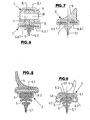
- the squeegee 5 held between the spring rails 6.1 is here provided on its upper side with a spoiler 4 formed integrally with the squeegee. That's also out FIG. 6 can be seen, which shows a cross section of a flat wiper blade in the region of the wiper blade adapter 7 and through the axis of the hinge pin 10.
- the spoiler 4 is formed as a separate part and attached or held on the spring rails 6.1.
- FIG. 7 can be seen, with a cross section outside the wiper blade adapter is shown here.
- a flat wiper blade 2 can also be designed so that the support element 6 is an elongated, elastic, the squeegee 5 with the head part receiving rail 6.2, where necessary one or more spring rails 6.1 made of metal or plastic material on or in the squeegee 5 and / or are arranged within the profile rail 6.2.
- the wiper blade adapter is attached to the profile rail 6.2 in such cases.
- At the top of the support member 6 can, as from FIG. 8 can be seen, an integrally connected to the rail spoiler 4 be present.
- a separately manufactured spoiler 4 attached to the top of the support member 6 forming rail 6.2, preferably clipped be.
- the wiper blades can of course be equipped in a conventional manner with other technical details, for example as in FIG. 9 indicated with liquid channels 4.1 and outlet openings 4.2 for the delivery of washing liquid to the disc to be cleaned.
- the first adapter part 8 is pivotally connected to the second adapter part 9 with a hinge pin 10 in such a way that a limited pivotal movement of the adapter part 8 and thus of the wiper blade 2 relative to the adapter part 9 and wiper blade 2 attached to the wiper arm 1 relative to the wiper arm 1 is possible, namely about the axis of the hinge pin 10, which is oriented perpendicular or transversely to a wiper lip 5.1 enclosing center plane of the wiper blade 2.
- the wiper blade adapter 7 is part of the detachable connection 3 between the wiper blade 2 and the wiper arm 1, wherein the wiper arm 1 is provided or formed with a wiper arm adapter 11 with a receiving or adapter opening 11.1 for this connection at its free end remote from the bearing piece 1.1 ,
- the adapter part 9 can be inserted from the free end 1.2 of the wiper arm 1 in a joining direction or in the Z axis into the adapter opening 11. in such a way that the adapter part 9 is then held in the adapter opening 11.1 positively and by latching.
- the first adapter part 8 of the wiper blade adapter 7 and the hinge pin 10 are made of metal and the second adapter part 9 is made as a molded part made of plastic.
- the adapter opening 11.1 of the wiper arm 1 is formed by a U-profile with the two parallel and spaced apart legs 12 and the yoke portion 13 connecting them.
- the legs 12 are each provided with bends 14 and 15, so that the adapter part 9 after insertion into the adapter opening 11.1 at its top and its two, parallel or substantially to the longitudinal extent of the wiper blade 2 Long sides positively embraced by the yoke section 13 and the legs 12 and thereby clearly guided during the joining.
- the angled portions 14 and 15 engage behind the adapter part 9 on its underside facing the adapter part 8 or the wiper blade 2 in a form-fitting manner.
- the second adapter part 9 is provided with a formed on a resilient tongue projection 16 which engages after insertion of the adapter part 9 in the adapter opening 11.1 as a locking means in a provided on the yoke portion 13 recess 17 and thereby the wiper blade adapter 7 by latching on the wiper arm 1 secures.
- the adapter opening 11.1 is further formed so that the U-profile is open to both the free end of the wiper arm and the Wischarmunterseite, which faces with mounted wiper arm 1 at least during the wiping operation of the vehicle window.
- the wiper blade 2 is formed as an electrically heated wiper blade.
- 4.1.weiquess provided an electrical heating element in or on the wiper blade 2 or in the spray channels.
- This heating element can have a variety of configurations, for example in the form of a heating foil or in the form of a heating wire. In the embodiment shown in the figures, the heating element consists of such a heating wire 18th
- the compound 3 is formed as a mechanical / electrical connection, in addition to the already mentioned above, the mechanical connection effecting elements a wiper blade-side electrical connection element 19 and a wiper arm-side connecting element 20.
- the two connecting elements 19 and 20 are each designed in a bipolar manner, specifically in the illustrated embodiment the connecting element 19 as a two-pole plug with the contact pins 19.1 and the connecting element 20 with the contact sockets 20.1.
- the connecting element 19 and to the contact pins 19.1 the two ends of the heating wire 18 are connected.
- the connecting element 20 and to the local contact sockets 20.1 the ends of a two-wire electrical supply line 21 are connected, which extends along the wiper arm 1 on the underside and over which the heatable wiper blade 2 is supplied with the required heating current from the vehicle-side electrical system. With the help of brackets or brackets 22, the line 21 is held on the underside of the wiper arm 1. If special designs or arrangements of the electrical heating elements so require, the wiper blade side or wischarm schemeen electrical connecting elements 19, 20 may also be equipped with more than two poles or contacts.
- the electrical connecting elements 19 and 20 each consist of a housing made of plastic as a housing 23 and 24.
- the housing 23 of the wiper blade-side connecting element 19 is shaped so that it forms a sleeve or bush-like housing portion 23.1, in its opening 25 the two pins 19.1 are added.
- the opening 25 is open at the end face of the housing section 23.1 adjacent to the free end of the contact pins 19.1.
- the housing 23 forms a housing portion 23.2, with which the housing 23 is held on the adapter part 9, in such a way that the axis of the opening 25 and thus the parallel to this axis and spaced plug contacts in wiper blade longitudinal direction respectively parallel to Wischarmlijnsraum, i. oriented in the direction of the Z-axis.
- three mutually perpendicular spatial axes are indicated in the figures, namely the X-axis, Y-axis and Z-axis, of which the X-axis and the Y-axis are transverse and the Z-axis parallel are oriented to the longitudinal extent of the wiper blade 2 and the wiper arm 1, as shown in the relevant figures.
- the second adapter part 9 is pivotable within certain limits relative to the first wiper blade support member 6 attached to the first adapter part 8.
- the direction defined as "joining direction" in the context of the invention runs in the direction of the spatial axis designated as Z-axis.
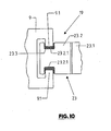
- the housing 23 of the wiper blade-side electrical connection element 19 is held floating on the second adapter part 9 in such a way that, to a limited extent, a movement of the housing 23 and thus of the electrical connection element 19 in the spatial plane transverse to the Z axis relative to the second Adapter part 9 is possible, as for example in the FIG. 3 is indicated with the running in the X-axis and the Y-axis double arrows.
- the floating connection between the housing 23 and the adapter part 9 is achieved, for example, by providing webs 9.1 molded onto the adapter part 9 with a sufficiently large Game engage in on the outer surface of the housing portion 23.2 shaped recesses 23.2.1.
- the floating arrangement of the housing 23 is conceivable, for example in the form that the housing 23 is held on the adapter part 9 via an elastic portion or an elastic material 23.3 and / or the housing 23 at least on its housing portion 23.2 or in total is made of an elastic material, so that the quasi-floating arrangement or connection of the housing is achieved with the adapter part 9 by the inherent elasticity of the housing portion 23.2.
- the attachment of the housing 23 to the second adapter part 9 is further such that the opening 25 faces away with its open side of the adapter part 9 and the housing projects beyond the narrow side of the adapter part 9.
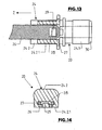
- the housing 24 of the wiper arm-side electrical connecting element 20 consists of a housing portion 24.1, in which the two contact sockets are accommodated 20.1, in such a way that these contacts are exposed on an end face of the housing portion 24.1 for receiving or inserting the contact pins 19.1.
- the housing portion 24.2 connects, with which the housing 24 is fixed by latching to a retaining tab or on a retaining plate 26, which in turn is held on the wiper arm 1 such that the housing 24 and thus the wischarm workede electrical connection element 20th be located within the adapter opening 11.1, in such a way that the contact bushes 20.1 having the end face of the housing portion 24.1 of the provided at the free end 1.2 of the wiper arm 1 open side of the adapter opening 11.1 spaced apart, as shown in the FIG. 11 is shown.
- the connection of the housing 24 with the wiper arm 1 via the holding plate 26 is such that the housing 24 and thus the wiper arm-side connecting element 20 is fixed or substantially fixed, ie not floating, provided in the adapter opening 11.1.
- the one has slit-shaped opening 27 adapted to the thickness and width of the holding plate 26, with which the housing 24 is pushed onto one end of the holding plate 26 and fixed there by latching.
- the holding plate 26 has an opening 28 into which engages by latching an integrally formed on the broadening 24.2.1 locking lug 29 latching.
- the housing portion 24.1 is adapted to the cross-section of the opening 25 on its outer surface, so that the housing portion 24 can be positively inserted into the opening 25 and thereby engage the plug contacts 19.1 in the contact bushes 20.1 and so the electrical connection between the electrical connection elements 19 and 20 and so that between the wiper blade side heating element and the connecting cable is made. Due to the floating arrangement of the connecting element 19 on the adapter part 9 as well as by the chamfer 30 of the housing portion 24.1 at its leading into the opening 25 when inserted into the opening automatically takes place a mutual alignment of the parts to be joined together. As a result, the trouble-free and secure electrical connection of the wiper blade 2 to the wiper arm 1 is ensured via the mechanical / electrical connection 3 at the same time as the mechanical connection.
- the two electrical connection elements 19 and 20 or their housings 23 and 24 are designed and arranged such that, after the mechanical and electrical connections have been established, the transition between the connection elements 19 and 20 or the housings 23 and 24 is sealed, in particular against a unwanted ingress of dirt and water or moisture. This is of great importance because windshield wiper systems usually have to have high reliability under rough external operating conditions.
- sealing the connection area between the housing parts sealing ribs For the sealing of the housing portion 24.1 at the transition to the enlarged diameter housing portion 24.2 provided with integrally formed, sealing the connection area between the housing parts sealing ribs.
- the wiper blade-side electrical connection element 19 is floating and the wiper arm-side connecting element 20 is not arranged floating or substantially non-floating, namely with a correspondingly rigid design of the holding plate 26.
- FIGS. 15 and 16 In contrast, an attachment of the wiper arm-side electrical connection element 20 or its housing 24 in such a way that this connection element is arranged floating or largely floating on the wiper arm 1 or in the adapter opening 11.1.
- the holding plate 26 is designed so that it acts like a leaf spring and thereby a floating attachment of the connecting elements 20 and the housing 24 in an axial direction substantially perpendicular to the surface sides of the holding plate 26, that is achieved in the direction of the X-axis, as this in the FIG. 16 with the orientation in the X-axis double arrow is indicated.
- this embodiment is then according to the FIG.
- the opening 27 is made to have a width in the Y-axis which is slightly larger than the width of the spring plate 26, so that for the fixed housing 24 also a mobility in the Y-axis is achieved, as in the FIG. 12 indicated by the double arrow in the Y-axis.
- the electrical connection element 20 is thus kept floating, again for easy connection of the electrical connection elements 19 and 20 at the same time in establishing the mechanical connection between the wiper blade 2 and the wiper arm. 1
Description
- Die Erfindung sich auf ein Wischblatt gemäß Oberbegriff Patentanspruch 1.
- Wischblätter zur Verwendung bei Scheibenwischanlagen zum Reinigen von Scheiben an Fahrzeugen, insbesondere an Kraftfahrzeugen, sind in verschiedenen Ausführungen bekannt. Bekannt sind dabei insbesondere auch als Bügelwischblätter ausgebildete Wischblätter (
JP 10-329655 - Bekannt sind weiterhin ebenfalls als Bügelwischblätter ausgebildete elektrisch beheizte Wischblätter (DE-GM 1 989 712), bei denen der elektrische Anschluss des im Wischblatt vorgesehenen Heizelementes über eine äußere, mit einem zweipoligen Stecker versehene und am Wischarm verlegte Versorgungsleitung erfolgt, und zwar durch Verbinden des Steckers mit seitlich am Wischblattkörper vorgesehene Buchsen. Nachteilig ist bei diesen bekannten Wischblättern, dass zusätzlich zu der mechanischen Verbindung zwischen Wischblatt und Wischarm die elektrische Verbindung gesondert hergestellt werden muss, und dass bei montiertem Wischblatt die Steckerverbindung zwischen der äußeren elektrischen Versorgungsleitung und dem Wischblatt nicht nur störend in Erscheinung tritt, sondern auch die Gefahr besteht, dass sich diese elektrische Verbindung während des Wischbetriebes in unerwünschter Weise löst.
- Aufgabe der Erfindung ist es, ein elektrisch beheiztes Wischblatt, in Form eines so genannten flachen Wischblattes bzw. so genannten Flachbalkenwischblattes aufzuzeigen, bei welchem bei der mechanischen Verbindung mit dem Wischarm zugleich die elektrische Verbindung mit einer äußeren elektrischen Versorgungsleitung in zuverlässiger Weise hergestellt wird, und zwar unabhängig von eventuellen durch die Fertigung und/oder Montage bedingten Toleranzen.
- Zur Lösung dieser Aufgabe ist ein Wischblatt entsprechend dem Patentanspruch 1 ausgebildet.
- Eine Besonderheit der Erfindung besteht darin, dass das wischblattseitige elektrische Verbindungselement in einer quer zur Fügerichtung orientierten Raumebene schwimmend bzw. auslenkbar, d.h. in gewissen Grenzen beweglich, vorgesehen ist. Es genügt also, wenn eines der beiden elektrischen Verbindungselemente schwimmend bzw. auslenkbar und das entsprechende andere, d.h. korrespondierende, elektrische Verbindungselement starr bzw. unbeweglich vorgesehen ist. Anders ausgedrückt, ist dieses andere, d.h. korrespondierende, elektrische Verbindungselement für ein Zusammenwirken mit einem elektrischen Verbindungselement ausgebildet ist, welches in einer quer zur Fügerichtung orientierten Raumebene schwimmend bzw. auslenkbar, d.h. in begrenztem Maß beweglich, gehalten ist. Letztendlich umfasst die Erfindung auch eine solche Konstellation, bei welcher beide zum Zusammenwirken bestimmte elektrische Verbindungselemente, d.h. sowohl das wischblattseitige als auch das das wischarmseitige elektrische Verbindungselement in einer quer zur Fügerichtung orientierten Raumebene schwimmend bzw. auslenkbar sind.
- Vorteilhaft ist ein zumindest teilweise aus Kunststoffmaterial gefertigter Wischblattadapter, wobei das erste, an dem Tragelement des Wischblattes befestigte Adapterteil als Formteil bzw. als Stanz- und Biegeteil aus Metall und das zweite Adapterteil als Formteil aus Kunststoff hergestellt ist. Das zweite Adapterteil, welches über ein Adaptergelenk gelenkig mit dem ersten Adapterteil verbunden ist, ist für eine formschlüssige Aufnahme im Wischarmadapter ausgebildet.
- In bestimmten Fällen kann es aber auch vorteilhaft sein, wenn das erste und das zweite Adapterteil des Wischblattadapters aus Kunststoffmaterial hergestellt sind.
- Weiterbildungen, Vorteile und Anwendungsmöglichkeiten der Erfindung ergeben sich auch aus der nachfolgenden Beschreibung von Ausführungsbeispielen und aus den Figuren. Dabei sind alle beschriebenen und/oder bildlich dargestellten Merkmale für sich oder in beliebiger Kombination grundsätzlich Gegenstand der Erfindung, unabhängig von ihrer Zusammenfassung in den Ansprüchen oder deren Rückbeziehung. Auch wird der Inhalt der Ansprüche zu einem Bestandteil der Beschreibung gemacht.
- Die Erfindung wird im Folgenden anhand der Figuren an Ausführungsbeispielen näher erläutert. Es zeigen:
- Fig. 1
- den Wischarm einer Scheibenwischanlage zusammen mit einem an diesem Wischarm befestigten Wischblatt gemäß der Erfindung;
- Fig. 2 und 3
- in Teildarstellung den Wischarm der
Figur 1 , zusammen mit den vom Wischarm abgenommenen Wischblatt im Bereich eines Wischblattadapters; - Fig. 4
- in vergrößerter Darstellung den am Wischblatt vorgesehenen Wischblattadapter;
- Fig. 5
- in perspektivischer Teildarstellung das Wischblatt, zusammen mit einem Element des Wischblattadapters sowie mit dem wischblattseitigen elektrischen Anschluss- oder Verbindungselement;
- Fig. 6 bis 9
- in Schnittdarstellung verschiedene Varianten von so genannten flachen Wischblättern bzw. Flachbalkenwischblättern,
- Fig. 10
- in vereinfachter Darstellung einen Schnitt entsprechend der Linie I - I der
Figur 4 im Bereich der "schwimmenden" Befestigung des wischblattseitigen elektrischen Verbindungselementes am Wischblattadapter; - Fig. 11
- den Wischarm der
Figur 1 in perspektivischer Teildarstellung und in einer Ansicht von unten; - Fig. 12
- das wischarmseitige elektrische Verbindungselement zusammen mit einem Halteblech in Seitenansicht;
- Fig. 13
- einen Schnitt entsprechend der Linie II -II der
Figur 12 ; - Fig. 14
- einen Schnitt entsprechend der Linie III - III der
Figur 12 ; - Fig. 15 und 16
- Darstellungen wie die
Figuren 13 und 14 bei einer weiteren Ausführungsform, die nicht Teil der Ansprüche ist. - In den Figuren ist mit 1 der Wischarm einer ansonsten nicht näher dargestellten Scheibenwischanlage für Fahrzeuge, beispielsweise für Straßenfahrzeuge, und mit 2 das an einem Ende des Wischarmes 1 mittels einer mechanischen/elektrischen Verbindung 3 lösbar befestigte Wischblatt bezeichnet. Im montierten Zustand ist der Wischarm 1 an seinem der Wischarm-Wischblatt-Verbindung 3 entfernt liegenden und von einem Lagerstück 1.1 gebildeten Ende an einer nicht dargerstellten Wischwelle eines ebenfalls nicht dargestellten Scheibenwischerantriebs befestigt.
- Das in den
Figuren 1-9 dargestellte Wischblatt 2 ist als so genanntes flaches Wischblatt bzw. Flachbalkenwischblatt ausgebildet. Es weist in bekannter Weise ein sich über die gesamte Länge des Wischblattes 2 erstreckendes Tragelement 6 auf, an welchem ein sich ebenfalls über die gesamte Länge des Wischblattes 2 erstreckender und aus einem elastomeren Kunststoff oder Gummi hergestellter Wischgummi 5 gehalten ist. - In den
Figuren 2-7 wird das Tragelement 6 von zwei flachen Federschienen 6.1 aus Federstahl gebildet, die in geeigneter Weise miteinander verbunden sind und die mit einem Teil ihrer Breite in Längsnuten an den Seiten des Wischgummis 5 eingreifen, wobei der andere Teil der Breite seitlich aus dem Wischgummi 5 hervorsteht. Zur lösbaren Befestigung des Wischblattes 2 ist an diesem in der Wischblattmitte oder etwa in der Wischblattmitte ein Wischblattadapter 7 vorgesehen, der zweiteilig ausgebildet ist und aus einem ersten Adapterteil 8 und einem zweiten Adapterteil 9 besteht, die mittels eines Gelenkbolzens 10 schwenkbar miteinander verbunden sind. Das Adapterteil 8 ist dabei mittelbar oder unmittelbar an dem von den Federschienen 6.1 gebildeten Tragelement 6 des Wischblattes 2 befestigt, und zwar den Wischgummi 5 an seiner der Wischlippe 5.1 abgewandten Oberseite reiterartig übergreifend. Hierfür besteht das erste Adapterteil 8 bei der dargestellten Ausführungsform aus zwei im Wesentlichen plattenförmigen Adapterteilelementen 8.1, von denen jedes an einer Längsseite des Wischblattes 2 einen dortigen Randbereich einer Federschiene 6.1 formschlüssig übergreifend vorgesehen ist. Die beiden Adapterteilelemente 8.1 sind über Verbindungselemente miteinander verbunden, so dass das von zwei Federschienen 6.1 gebildete Tragelement 6 zwischen den Adapterteilelementen 8.1 gehalten ist. Der zwischen den Federschienen 6.1 gehaltene Wischgummi 5 ist hier an seiner Oberseite mit einem einstückig mit dem Wischgummi ausgebildeten Spoiler 4 versehen. Das ist auch ausFigur 6 ersichtlich, die einen Querschnitt eines flachen Wischblattes im Bereich des Wischblattadapters 7 und zwar durch die Achse des Gelenkbolzens 10 zeigt. - Es ist auch möglich, dass der Spoiler 4 als separates Teil ausgebildet und an den Federschienen 6.1 befestigt bzw. gehalten ist. Eine solche Ausgestaltung ist aus
Figur 7 ersichtlich, wobei hier ein Querschnitt außerhalb des Wischblattadapters gezeigt ist. - Ein flaches Wischblatt 2 kann stattdessen auch so gestaltet sein, dass das Tragelement 6 eine längliche, elastische, den Wischgummi 5 mit dessen Kopfteil aufnehmende Profilschiene 6.2 ist, wobei erforderlichenfalls eine oder mehrere Federschienen 6.1 aus Metall oder auch aus Kunststoffmaterial am oder im Wischgummi 5 und/oder innerhalb der Profilschiene 6.2 angeordnet sind. Der Wischblattadapter ist in solchen Fällen an der Profilschiene 6.2 angebracht. An der Oberseite des Tragelementes 6 kann, wie aus
Figur 8 ersichtlich, ein einstückig mit der Profilschiene verbundener Spoiler 4 vorhanden sein. Stattdessen kann, wie inFigur 9 gezeigt, auch ein separat hergestellter Spoiler 4 an der Oberseite der das Tragelement 6 bildenden Profilschiene 6.2 angebracht, bevorzugt aufgeklipst, sein. Die Wischblätter können natürlich in an sich bekannter Weise mit weiteren technischen Details ausgestattet sein, beispielsweise wie inFigur 9 angedeutet mit Flüssigkeitskanälen 4.1 und Austrittsöffnungen 4.2 für die Abgabe von Waschflüssigkeit auf die zu reinigende Scheibe. - Das erste Adapterteil 8 ist mit einem Gelenkbolzen 10 gelenkig mit dem zweiten Adapterteil 9 verbunden, und zwar in der Weise, dass eine begrenzte Schwenkbewegung des Adapterteils 8 und damit des Wischblattes 2 relativ zum Adapterteil 9 und bei am Wischarm 1 befestigtem Wischblatt 2 relativ zum Wischarm 1 möglich ist, und zwar um die Achse des Gelenkbolzens 10, die senkrecht oder quer zu einer die Wischlippe 5.1 einschließenden Mittelebene des Wischblattes 2 orientiert ist.
- Der Wischblattadapter 7 ist Teil der lösbaren Verbindung 3 zwischen dem Wischblatt 2 und dem Wischarm 1, wobei der Wischarm 1 für diese Verbindung an seinem freien, dem Lagerstück 1.1 entfernt liegenden Ende mit einem Wischarmadapter 11 mit einer Aufnahme- oder Adapteröffnung 11.1 versehen oder ausgebildet ist. In die Adapteröffnung 11.1 ist das Adapterteil 9 von dem freien Ende 1.2 des Wischarmes 1 her in einer Fügerichtung bzw. in der Z-Achse einsetzbar, und zwar derart, dass das Adapterteil 9 dann in der Adapteröffnung 11.1 formschlüssig und durch Verrasten gehalten ist. Das erste Adapterteil 8 des Wischblattadapters 7 und der Gelenkbolzen 10 sind aus Metall und das zweite Adapterteil 9 ist als Formteil aus Kunststoff gefertigt.
- Für die formschlüssige Anordnung des zweiten Adapterteils 9 ist die Adapteröffnung 11.1 des Wischarmes 1 von einem U-Profil mit den beiden parallel und im Abstand voneinander angeordneten Schenkeln 12 und dem diese verbindenden Jochabschnitt 13 gebildet. An dem dem Jochabschnitt 13 entfernt liegenden freien Rand sind die Schenkel 12 jeweils mit Abwinklungen 14 und 15 versehen, so dass das Adapterteil 9 nach dem Einsetzen in die Adapteröffnung 11.1 an seiner Oberseite und seinen beiden, parallel oder im Wesentlichen zur Längserstreckung des Wischblattes 2 verlaufenden Längsseiten formschlüssig von dem Jochabschnitt 13 und den Schenkeln 12 umgriffen und hierdurch beim Fügen eindeutig geführt wird. Weiterhin hintergreifen die Abwinklungen 14 und 15 das Adapterteil 9 auch an seiner dem Adapterteil 8 bzw. dem Wischblatt 2 zugewandten Unterseite formschlüssig. An der Oberseite ist das zweite Adapterteil 9 mit einem an einer federnden Zunge ausgebildeten Vorsprung 16 versehen, der nach dem Einsetzen des Adapterteils 9 in die Adapteröffnung 11.1 als Rastmittel in eine am Jochabschnitt 13 vorgesehene Ausnehmung 17 eingreift und dadurch den Wischblattadapter 7 durch Verrasten am Wischarm 1 sichert.
- Wie insbesondere die
Figur 11 zeigt, ist die Adapteröffnung 11.1 weiterhin so ausgebildet, dass das U-Profil sowohl zum freien Ende des Wischarmes als auch zur Wischarmunterseite offen ist, die bei montiertem Wischarm 1 zumindest während des Wischbetriebes der Fahrzeugscheibe zugewandt ist. - Um ein Vereisen des Wischblattes 2 und dabei beispielsweise des die Wischlippe 5.1 mit dem restlichen Teil des Wischgummis 5 verbindenden Kippsteges und/oder eines oder mehrerer Spritzkanäle 4.1 zu vermeiden, die im aufgesetzten Spoilerteil 4 (
Figur 9 ) oder auch im Wischgummi oder an der Profilschiene 6.2 ausgebildet bzw. vorgesehen und mit einer Vielzahl von Austrittsöffnungen 4.2 zum Ausbringen einer Wasch- und Reinigungsflüssigkeit auf die Fahrzeugscheibe versehen sind, ist das Wischblatt 2 als elektrisch beheiztes Wischblatt ausgebildet. Hierfür ist im bzw. am Wischblatt 2 oder aber in den Spritzkanälen 4.1.wenigstens ein elektrisches Heizelement vorgesehen. Dieses Heizelement kann die unterschiedlichsten Ausbildungen aufweisen, beispielsweise in Form einer Heizfolie oder aber in Form eines Heizdrahtes. Bei der in den Figuren dargestellten Ausführungsform besteht das Heizelement aus einem derartigen Heizdraht 18. - Um bei der mechanischen Befestigung des Wischblattes 2 am Wischarm 1 zugleich auch automatisch, d.h. allein durch das Einführen des Adapterteils 9 in die Adapteröffnung 11.1, die erforderliche elektrische Verbindung zum Heizelement bzw. Heizdraht 18 herzustellen, ist die Verbindung 3 als mechanisch/elektrische Verbindung ausgebildet, und zwar zusätzlich zu den bereits vorstehend erwähnten, die mechanische Verbindung bewirkenden Elementen mit einem wischblattseitigen elektrischen Verbindungselement 19 und einem wischarmseitigen Verbindungselement 20.
- Die beiden Verbindungselemente 19 und 20 sind jeweils zweipolig ausgeführt, und zwar bei der dargestellten Ausführungsform das Verbindungselement 19 als zweipoliger Stecker mit den Kontaktstiften 19.1 und das Verbindungselement 20 mit den Kontaktbuchsen 20.1. An das Verbindungselement 19 bzw. an die Kontaktstifte 19.1 sind die beiden Enden des Heizdrahtes 18 angeschlossen. An das Verbindungselement 20 bzw. an die dortigen Kontaktbuchsen 20.1 sind die Enden einer zweiadrigen elektrischen Versorgungsleitung 21 angeschlossen, die entlang des Wischarmes 1 an dessen Unterseite verläuft und über die das beheizbare Wischblatt 2 mit dem erforderlichen Heizstrom aus dem fahrzeugseitigen Bordnetz versorgt wird. Mit Hilfe von Halterungen bzw. Klammern 22 ist die Leitung 21 an der Unterseite des Wischarmes 1 gehalten. Wenn spezielle Ausbildungen oder Anordnungen der elektrischen Heizelemente dies erfordern, können die wischblattseitigen bzw. wischarmseitigen elektrischen Verbindungselemente 19, 20 auch mit mehr als zwei Polen bzw. Kontakten ausgestattet sein.
- Die elektrischen Verbindungselemente 19 bzw. 20 bestehen jeweils aus einem als Formteil aus Kunststoff hergestellten Gehäuse 23 bzw. 24. Das Gehäuse 23 des wischblattseitigen Verbindungselementes 19 ist dabei so geformt, dass es einen hülsen- oder buchsenartigen Gehäuseabschnitt 23.1 bildet, in dessen Öffnung 25 die beiden Kontaktstifte 19.1 aufgenommen sind. Die Öffnung 25 ist an der dem freien Ende der Kontaktstifte 19.1 benachbarten Stirnseite des Gehäuseabschnittes 23.1 offen. Weiterhin bildet das Gehäuse 23 einen Gehäuseabschnitt 23.2, mit dem das Gehäuse 23 am Adapterteil 9 gehalten ist, und zwar derart, dass die Achse der Öffnung 25 und damit auch die zu dieser Achse parallelen und voneinander beabstandeten Steckerkontakte in Wischblattlängsrichtung respektive parallel zur Wischarmlängsrichtung, d.h. in Richtung der Z-Achse orientiert sind.
- Zum besseren Verständnis der nachfolgenden Ausführungen sind in den Figuren jeweils drei senkrecht zueinander orientierte Raumachsen angegeben, nämlich die X-Achse, Y-Achse und Z-Achse, von denen die X-Achse und die Y-Achse quer und die Z-Achse parallel zur Längserstreckung des Wischblattes 2 bzw. des Wischarmes 1 orientiert sind, so wie das in den betreffenden Figuren dargestellt ist. Bei dieser vorstehenden Definition der Orientierung der Raumachsen wurde ausdrücklich vernachlässigt, dass das zweite Adapterteil 9 in gewissen Grenzen relativ zu dem am Wischblatttragelement 6 befestigten ersten Adapterteil 8 verschwenkbar ist. Die im Zusammenhang mit der Erfindung als "Fügerichtung" definierte Richtung verläuft in Richtung der als Z-Achse bezeichneten Raumachse.
- Bei der in den
Figuren 2 -5 und10 - 14 dargestellten Ausführungsform ist das Gehäuse 23 des wischblattseitigen elektrischen Verbindungselementes 19 schwimmend an dem zweiten Adapterteil 9 gehalten, und zwar derart, dass in einem begrenzten Ausmaß eine Bewegung des Gehäuses 23 und damit des elektrischen Verbindungselementes 19 in der Raumebene quer zur Z-Achse relativ zum zweiten Adapterteil 9 möglich ist, wie dies z.B. in derFigur 3 mit den in der X-Achse und der Y-Achse verlaufenden Doppelpfeilen angedeutet ist. Die schwimmende Verbindung zwischen dem Gehäuse 23 und dem Adapterteil 9 ist beispielsweise dadurch erreicht, dass an das Adapterteil 9 angeformte Stege 9.1 mit ausreichend großem Spiel in an der Außenfläche des Gehäuseabschnittes 23.2 geformte Ausnehmungen 23.2.1 eingreifen. Auch andere Möglichkeiten für die schwimmende Anordnung des Gehäuses 23 sind denkbar, beispielsweise in der Form, dass das Gehäuse 23 über einen elastischen Abschnitt oder ein elastisches Material 23.3 am Adapterteil 9 gehalten ist und/oder das Gehäuse 23 zumindest an seinem Gehäuseabschnitt 23.2 oder aber insgesamt aus einem elastischen Material hergestellt ist, so dass die quasi schwimmende Anordnung oder Verbindung des Gehäuses mit dem Adapterteil 9 durch die Eigenelastizität des Gehäuseabschnitts 23.2 erreicht ist. - Die Befestigung des Gehäuses 23 an dem zweiten Adapterteil 9 ist weiterhin so, dass die Öffnung 25 mit ihrer offenen Seite dem Adapterteil 9 abgewandt ist und das Gehäuse über die Schmalseite des Adapterteils 9 vorsteht.
- Das Gehäuse 24 des wischarmseitigen elektrischen Verbindungselementes 20 besteht aus einem Gehäuseabschnitt 24.1, in dem die die beiden Kontaktbuchsen 20.1 aufgenommen sind, und zwar derart, dass diese Kontakte an einer Stirnseite des Gehäuseabschnitts 24.1 zur Aufnahme oder zum Einführen der Kontaktstifte 19.1 freiliegen. An den Gehäuseabschnitt 24.1 schließt sich der Gehäuseabschnitt 24.2 an, mit dem das Gehäuse 24 durch Verrasten an einer Haltelasche oder an einem Halteblech 26 befestigt ist, welches seinerseits am Wischarm 1 derart gehalten ist, dass sich das Gehäuse 24 und damit das wischarmseitige elektrische Verbindungselement 20 innerhalb der Adapteröffnung 11.1 befinden, und zwar in der Weise, dass die die Kontaktbuchsen 20.1 aufweisende Stirnseite des Gehäuseabschnittes 24.1 der am freien Ende 1.2 des Wischarmes 1 vorgesehenen offenen Seite der Adapteröffnung 11.1 mit Abstand gegenüberliegt, wie dies in der
Figur 11 dargestellt ist. Die Verbindung des Gehäuses 24 mit dem Wischarm 1 über das Halteblech 26 ist derart, dass das Gehäuse 24 und damit das wischarmseitige Verbindungselement 20 fest oder im Wesentlichen fest, d.h. nicht schwimmend, in der Adapteröffnung 11.1 vorgesehen ist. - Für die verrastende Verbindung des Gehäuses 24 an dem Halteblech 26 ist der Gehäuseabschnitt 24.2 mit einer seitlichen Verbreiterung 24.2.1 versehen, die eine an die Dicke und Breite des Halteblechs 26 angepasste schlitzförmige Öffnung 27 aufweist, mit der das Gehäuse 24 auf ein Ende des Halteblechs 26 aufgeschoben und dort durch Verrasten fixiert ist. Hierfür weist das Halteblech 26 eine Öffnung 28 auf, in die durch Verrasten eine an der Verbreiterung 24.2.1 angeformte Rastnase 29 verrastend eingreift.
- Der Gehäuseabschnitt 24.1 ist an seiner Außenfläche dem Querschnitt der Öffnung 25 angepasst, so dass der Gehäuseabschnitt 24 formschlüssig in die Öffnung 25 eingeführt werden kann und dabei die Steckerkontakte 19.1 in die Kontaktbuchsen 20.1 eingreifen und so die elektrische Verbindung zwischen den elektrischen Verbindungselementen 19 und 20 und damit zwischen dem wischblattseitigen Heizelement und der Anschlussleitung hergestellt wird. Durch die schwimmende Anordnung des Verbindungselementes 19 am Adapterteil 9 sowie auch durch die Abschrägung 30 des Gehäuseabschnittes 24.1 an seiner beim Einführen in die Öffnung 25 vorauseilenden Stirnseite erfolgt automatisch eine gegenseitige Ausrichtung der miteinander zu verbindenden Teile. Dadurch ist über die mechanisch/elektrische Verbindung 3 zugleich mit dem mechanischen Verbinden auch das problemlose und sichere elektrische Verbinden des Wischblattes 2 mit dem Wischarm 1 gewährleistet.
- Die beiden elektrischen Verbindungselemente 19 und 20 bzw. deren Gehäuse 23 und 24 sind so ausgebildet und angeordnet, dass nach dem Herstellen der mechanischen und elektrischen Verbindungen der Übergang zwischen den Verbindungselementen 19 und 20 bzw. den Gehäusen 23 und 24 abgedichtet ist, insbesondere gegen ein unerwünschtes Eindringen von Schmutz und Wasser bzw. Feuchtigkeit. Dies ist deswegen von großer Bedeutung, weil Scheibenwischanlagen in der Regel unter rauhen äußeren Betriebsbedingungen eine hohe Funktionssicherheit aufweisen müssen. Für die Abdichtung ist der Gehäuseabschnitt 24.1 am Übergang zu dem einen vergrößerten Durchmesser aufweisenden Gehäuseabschnitt 24.2 mit angeformten, den Anschlussbereich zwischen den Gehäuseteilen abdichtenden Dichtungsrippen versehen.
- Vorstehend wurde davon ausgegangen, dass das wischblattseitige elektrische Verbindungselement 19 schwimmend und das wischarmseitige Verbindungselement 20 nicht schwimmend oder im Wesentlichen nicht schwimmend angeordnet sind, und zwar bei entsprechend starrer Ausbildung des Halteblechs 26.
- Die
Figuren 15 und 16 zeigen demgegenüber eine Befestigung des wischarmseitigen elektrischen Verbindungselementes 20 bzw. dessen Gehäuses 24 in der Weise, dass dieses Verbindungselement schwimmend oder weitestgehend schwimmend am Wischarm 1 oder in der Adapteröffnung 11.1 angeordnet ist. Hierfür ist das Halteblech 26 so ausgeführt, dass es blattfederartig wirkt und dadurch eine schwimmende Befestigung des Verbindungselemente 20 bzw. des Gehäuses 24 in einer Achsrichtung im Wesentlichen senkrecht zu den Oberflächenseiten des Halteblechs 26, d.h. in Richtung der X-Achse erreicht wird, wie dies in derFigur 16 mit dem in der X-Achse orientieren Doppelpfeil angedeutet ist. Bei dieser Ausführungsform ist dann entsprechend derFigur 15 die Öffnung 27 so ausgeführt, dass sie in der Y-Achse eine Breite aufweist die etwas größer ist als die Breite des Federblechs 26, so dass für das befestigte Gehäuse 24 auch eine Beweglichkeit in der Y-Achse erreicht ist, wie dies in derFigur 12 mit dem Doppelpfeil in der Y-Achse angedeutet ist. Das elektrische Verbindungselement 20 ist somit schwimmend gehalten, und zwar wiederum für ein problemloses Verbinden der elektrischen Verbindungselemente 19 und 20 zugleich beim Herstellen der mechanischen Verbindung zwischen dem Wischblatt 2 und dem Wischarm 1. -
- 1
- Wischarm
- 1.1
- Gelenkträger
- 1.2
- freies Ende des Wischarmes
- 2
- Wischblatt
- 3
- mechanisch/elektrische Verbindungsanordnung
- 4
- Spoiler
- 4.1
- Flüssigkeltskanal
- 4.2
- Austrittsöffnung
- 5
- Wischgummi
- 5.1
- Wischlippe
- 6
- Tragelement
- 6.1
- Federschiene
- 6.2
- Profilschiene
- 7
- Wischblattadapter
- 8
- erstes Adapterteil
- 9
- zweites Adapterteil
- 8.1
- Adapterteilelement
- 9.1
- Steg
- 9.2
- elastisches Material
- 10
- Gelenkbolzen
- 11
- Wischarmadapter
- 11.1
- Adapteröffnung
- 12
- Schenkel
- 13
- Jochabschnitt
- 14, 15
- Abwinklung
- 16
- Vorsprung
- 17
- Öffnung
- 18
- Heizdraht
- 19, 20
- elektrisches Verbindungselement
- 19.1
- Kontaktstift
- 20.1
- Kontaktbuchse
- 21
- elektrische Versorgungsleitung
- 22
- Befestigungselement
- 23, 24
- Gehäuse
- 23.1, 23.2
- Gehäuseabschnitt
- 23.2.1
- Ausnehmung
- 24.1, 24.2
- Gehäuseabschnitt
- 24.2.1
- Verbreiterung
- 25
- Öffnung
- 26
- Halteblech
- 27
- Öffnung
- 28
- Öffnung
- 29
- Rast
- 30
- Fase oder Abschrägung
- X, Y, Z
- Raumachse
Claims (12)
- Flaches Wischblatt zum Reinigen von Scheiben an Fahrzeugen mit wenigstens einem länglichen Tragelement (6), an welchem ein zumindest eine Wischlippe (5.1) aufweisender Wischgummi (5) gehalten ist, mit einem an dem Tragelement (6) befestigten Wischblattadapter (7), der zum lösbaren mechanischen Verbinden des Wischblattes (2) mit einem Wischarm (1) bzw. mit einem am Wischarm (1) vorgesehenen Wischarmadapter (11) in einer Fügerichtung (Z-Achse) ausgebildet ist, mit wenigstens einem an dem Wischblatt (2) vorgesehenen elektrischen Heizelement, sowie mit wenigstens einem am Wischblattadapter (7) vorgesehenen wischblattseitigen elektrischen Verbindungselement (19), welches zumindest einen elektrischen Kontakt aufweist, zum Herstellen einer elektrischen Verbindung zwischen dem Heizelement und einer am Wischarm (1) vorgesehenen bzw. gehaltenen Stromzufuhr, wobei das wischblattseitige elektrische Verbindungselement (19) zum lösbaren Verbinden mit einem am Wischarm (1) bzw. am Wischarmadapter (11) vorgesehenen wischarmseitigen elektrischen Verbindungselement (20) in der gleichen Fügerichtung (Z-Achse) wie die des Wischblattadapters (11) ausgebildet ist, und wobei,
das wischblattseitige elektrische Verbindungselement (19) in einer quer zur Fügerichtung (Z- Achse) orientierten Raumebene (X-Y-Achse) schwimmend bzw. auslenkbar angebracht ist. - Flaches Wischblatt nach Anspruch 1 , dadurch gekennzeichnet, dass der Wischblattadapter (7) mit Mitteln zum Verrasten bzw. Verriegeln mit dem Wischarm (1) bzw. dem Wischarmadapter (11) ausgestattet ist.
- Flaches Wischblatt nach Anspruch 1 oder 2, dadurch gekennzeichnet, dass der Wischblattadapter (7) aus wenigstens zwei über ein Adaptergelenk (10) gelenkig miteinander verbundenen Adapterteilen (8, 9) besteht, von denen das erste Adapterteil (8) an dem Tragelement (4) befestigt und das zweite Adapterteil (9) für eine Verbindung mit dem Wischarm (1) bzw. dem Wischarmadapter (11) ausgebildet ist.
- Flaches Wischblatt nach einem der vorhergehenden Ansprüche, dadurch gekennzeichnet, dass das wenigstens eine wischblattseitige elektrische Verbindungselement (19) an einer quer zur Fügerichtung (Z-Achse) orientierten Schmal- oder Stirnseite des Wischblattadapters (7) bzw. des zweiten Adapterteils (9) und dabei für die elektrische Verbindung zugänglich und/oder über diese Schmal- oder Stirnseite hervorstehend ist.
- Flaches Wischblatt nach einem der vorhergehenden Ansprüche, dadurch gekennzeichnet, dass der wenigstens eine elektrische Kontakt des wischblattseitigen Verbindungselementes (19) ein Kontaktstift (19.1) oder eine Kontaktbuchse ist und mit der Achse in Fügerichtung (Z-Achse) orientiert ist.
- Flaches Wischblatt nach einem der vorhergehenden Ansprüche, dadurch gekennzeichnet, dass das wenigstens eine wischblattseitige elektrische Verbindungselement (19) ein Gehäuse (23) aus einem elektrisch isolierenden Material mit einem buchsenartigen Gehäuseabschnitt (23.1) aufweist, welcher mit seiner Achse in Fügerichtung (Z-Achse) orientiert ist und welcher zur Aufnahme eines korrespondierenden Gehäuseabschnittes (24.1) eines Gehäuseabschnittes des wischarmseitigen elektrischen Verbindungselementes (20) ausgebildet ist, und dass in dem buchsenartigen Gehäuseabschnitt (23.1) der wenigstens eine elektrische Kontakt des wischblattseitigen Verbindungselementes (19) angeordnet ist.
- Flaches Wischblatt nach einem der Ansprüche 1 bis 5, dadurch gekennzeichnet, dass das wenigstens eine wischblattseitige elektrische Verbindungselement (19) ein Gehäuse (23) aus einem elektrisch isolierenden Material mit einem in Fügerichtung (Z-Achse) orientierten zapfenartigen Gehäuseabschnitt aufweist, welcher zum passenden Einführen in einen buchsenartigen Gehäuseabschnitt des wischarmseitigen elektrischen Verbindungselementes (20) ausgebildet, und dass an dem zapfenartigen Gehäuseabschnitt der wenigstens eine elektrische Kontakt des wischblattseitigen Verbindungselementes (19) vorgesehen ist.
- Flaches Wischblatt nach einem der vorhergehenden Ansprüche, dadurch gekennzeichnet, dass die Fügerichtung (Z-Achse) in Längsrichtung des Wischblattes (2) bzw. des Wischarmes (1) orientiert ist.
- Flaches Wischblatt nach einem der vorhergehenden Ansprüche, dadurch gekennzeichnet, dass das elektrische Heizelement von wenigstens einer Heizfolie oder von wenigstens einem Heizdraht (18) gebildet ist.
- Flaches Wischblatt nach einem der vorhergehenden Ansprüche, dadurch gekennzeichnet, dass der Wischblattadapter (7) bzw. dessen zweites Adapterteil (9) für eine formschlüssige Aufnahme in einer von dem Wischarmadapter (11) gebildeten Öffnung (11.1) ausgebildet ist.
- Flaches Wischblatt nach einem der vorhergehenden Ansprüche, dadurch gekennzeichnet, dass es als so genanntes flaches Wischblatt bzw. als so genanntes Flachbalkenwischblatt ausgebildet ist.
- Scheibenwischanlage, umfassend ein Flaches Wischblatt nach einem der Ansprüche 1 bis 11 und einen Wischarm.
Priority Applications (1)
| Application Number | Priority Date | Filing Date | Title |
|---|---|---|---|
| PL09761480T PL2282917T3 (pl) | 2008-06-10 | 2009-06-10 | Pióro wycieraczki oraz ramię wycieraczki szyby |
Applications Claiming Priority (2)
| Application Number | Priority Date | Filing Date | Title |
|---|---|---|---|
| DE102008027566A DE102008027566A1 (de) | 2008-06-10 | 2008-06-10 | Wischblatt sowie Wischarm |
| PCT/EP2009/004178 WO2009149917A1 (de) | 2008-06-10 | 2009-06-10 | Wischblatt sowie wischarm |
Publications (2)
| Publication Number | Publication Date |
|---|---|
| EP2282917A1 EP2282917A1 (de) | 2011-02-16 |
| EP2282917B1 true EP2282917B1 (de) | 2014-05-28 |
Family
ID=41020851
Family Applications (1)
| Application Number | Title | Priority Date | Filing Date |
|---|---|---|---|
| EP09761480.4A Active EP2282917B1 (de) | 2008-06-10 | 2009-06-10 | Wischblatt sowie wischarm |
Country Status (7)
| Country | Link |
|---|---|
| US (3) | US9452736B2 (de) |
| EP (1) | EP2282917B1 (de) |
| JP (1) | JP5603330B2 (de) |
| CN (1) | CN102119094B (de) |
| DE (1) | DE102008027566A1 (de) |
| PL (1) | PL2282917T3 (de) |
| WO (1) | WO2009149917A1 (de) |
Families Citing this family (30)
| Publication number | Priority date | Publication date | Assignee | Title |
|---|---|---|---|---|
| DE102008027566A1 (de) * | 2008-06-10 | 2009-12-17 | Valeo Systèmes d'Essuyage | Wischblatt sowie Wischarm |
| DE102009059120A1 (de) * | 2009-12-19 | 2011-06-22 | Daimler AG, 70327 | Kopplungsteil zum Verbinden eines Wischarms mit einem Wischblatt und Verbindungseinrichtung mit einem Kopplungsteil |
| DE102009059122A1 (de) * | 2009-12-19 | 2011-06-22 | Daimler AG, 70327 | Anschlussteil zum Verbinden eines Wischarms mit einem Wischblatt |
| DE102010005274A1 (de) * | 2010-01-20 | 2011-07-21 | Valeo Wischersysteme GmbH, 74321 | Wischblatt, Adapter sowie Werkzeugvorrichtung zum Herstellen eines Adapters |
| DE102010007557A1 (de) * | 2010-02-10 | 2011-08-11 | Valeo Wischersysteme GmbH, 74321 | Wischvorrichtung für Fahrzeugscheiben und Wischblatt mit einer Heizeinrichtung |
| CA3091633A1 (en) | 2010-04-23 | 2011-10-27 | Steam Tech, Llc | Surface wiper system |
| FR2962093B1 (fr) * | 2010-06-30 | 2012-08-24 | Valeo Systemes Dessuyage | Connecteur d'essuie-glace a contact electrique interne faisant ressort |
| FR2962091B1 (fr) * | 2010-06-30 | 2016-10-14 | Valeo Systemes Dessuyage | Connecteur d'essuie-glace multifonctions |
| FR2962092B1 (fr) * | 2010-06-30 | 2013-06-28 | Valeo Systemes Dessuyage | Adaptateur d'essuie-glace a contacts electriques |
| DE102010025687A1 (de) * | 2010-06-30 | 2012-01-05 | Valeo Wischersysteme Gmbh | Wischblatt zum Reinigen von Fahrzeugscheiben |
| FR2968259B1 (fr) | 2010-12-02 | 2016-04-29 | Valeo Systemes Dessuyage | Ensemble comprenant une piece terminale d'un bras d'essuie-glace et un connecteur electrique |
| DE102011053991A1 (de) * | 2011-09-27 | 2013-03-28 | Valeo Systèmes d'Essuyage | Wischblatt zum Reinigen von Fahrzeugscheiben |
| DE102011055948A1 (de) | 2011-12-01 | 2013-06-06 | Valeo Systèmes d'Essuyage | Wischblatt zum Reinigen einer Fahrzeugscheibe |
| DE102012106837A1 (de) * | 2012-07-27 | 2014-05-15 | Valeo Wischersysteme Gmbh | Wischblatt zum Reinigen von Fahrzeugscheiben |
| FR3007360B1 (fr) * | 2013-06-20 | 2015-07-03 | Valeo Systemes Dessuyage | Dispositif chauffant destine a un balai d’essuie-glace et balai d’essuie-glace comportant un tel dispositif chauffant |
| FR3015399B1 (fr) * | 2013-12-20 | 2017-03-31 | Valeo Systemes Dessuyage | Dispositif de connexion electrique pour balai d'essuyage de systeme d'essuyage de vehicule automobile |
| US10587218B2 (en) | 2015-09-07 | 2020-03-10 | Steam Tech, Llc | Panel maintenance system |
| DE102016204243A1 (de) * | 2016-03-15 | 2017-09-21 | Robert Bosch Gmbh | Wischvorrichtung mit einem Wischarmadapter |
| FR3049153B1 (fr) * | 2016-03-21 | 2018-04-06 | Valeo Systemes D'essuyage | Circuit electrique chauffant et element chauffant pour balai d’essuie-glace, procede de realisation d’un element chauffant, et balai d’essuie-glace |
| CN108082129A (zh) * | 2016-11-21 | 2018-05-29 | 株式会社美姿把 | 刮水器刮片 |
| AU2018308154A1 (en) * | 2017-07-28 | 2020-02-06 | Pylon Manufacturing Corp. | Windshield wiper connector and assembly |
| US20190063047A1 (en) * | 2017-08-23 | 2019-02-28 | Youshi (Xiamen) Sanitary Ware Industrial Co., Ltd. | Water pipe structure of basin faucet |
| US11638939B2 (en) | 2018-11-27 | 2023-05-02 | Steam Tech, Llc | Mobile panel cleaner |
| US11142167B2 (en) | 2019-01-07 | 2021-10-12 | Steam Tech, Llc | Wiper blade with directionally differentiated motion |
| WO2020264586A1 (en) * | 2019-06-28 | 2020-12-30 | Trico Products Corporation | Multiple wiper blade adapter for wiper blade assembly |
| DE102019212235A1 (de) * | 2019-08-15 | 2021-02-18 | Robert Bosch Gmbh | Scheibenwischervorrichtung |
| DE102020202352A1 (de) * | 2020-02-24 | 2021-08-26 | Te Connectivity Germany Gmbh | Winkelsteckverbindung, elektrischer Stecker für eine solche Winkelsteckverbindung und elektrisch beheizter Scheibenwischer mit einer solchen Winkelsteckverbindung |
| RU208348U1 (ru) * | 2021-02-19 | 2021-12-14 | Федеральное государственное казенное военное образовательное учреждение высшего образования "Военный университет" Министерства обороны Российской Федерации | Устройство защиты бортовой сети транспортного средства при примерзании щеток стеклоочистителя |
| DE102021205106A1 (de) * | 2021-05-19 | 2022-11-24 | Robert Bosch Gesellschaft mit beschränkter Haftung | Wischblattvorrichtung und Wischersystem |
| DE102022205245A1 (de) * | 2022-05-25 | 2023-11-30 | Robert Bosch Gesellschaft mit beschränkter Haftung | Wischervorrichtung, Wischer mit einer Wischervorrichtung und Verfahren zur Montage einer Wischervorrichtung |
Family Cites Families (32)
| Publication number | Priority date | Publication date | Assignee | Title |
|---|---|---|---|---|
| US2119587A (en) * | 1936-07-07 | 1938-06-07 | Foster W Lamb | Heated vehicle windshield wiper |
| US2587129A (en) * | 1951-03-01 | 1952-02-26 | Frederick C Fehrman | Animal mouth opener |
| US2755499A (en) * | 1954-03-22 | 1956-07-24 | Wilburt W Mays | Electrically heated windshield wiper |
| US3085277A (en) * | 1958-08-08 | 1963-04-16 | Rau Swf Autozubehoer | Connecting device for windshield wiper |
| US3201818A (en) | 1964-05-12 | 1965-08-24 | Windshield wiper and method of producing the same | |
| US3192551A (en) * | 1964-08-31 | 1965-07-06 | Walter D Appel | Windshield wiper blade assembly |
| US3408678A (en) * | 1966-08-17 | 1968-11-05 | Roy E. Linker | Windshield wiper assembly |
| US3419932A (en) | 1967-08-03 | 1969-01-07 | Roy E. Linker | Windshield wiper assembly |
| US3461477A (en) * | 1968-01-30 | 1969-08-19 | Jimmie Ray Ikner | Heated wiper blade |
| DE1989712U (de) | 1968-02-20 | 1968-07-18 | Heinz Kern | Scheibenwischer fuer kraftfahrzeuge. |
| US3587129A (en) | 1968-11-04 | 1971-06-28 | Roy E Linker | Electrically heated windshield wiper assembly |
| US3639938A (en) * | 1969-10-15 | 1972-02-08 | Gerald J Golden | Windshield-cleaning system |
| US3718940A (en) * | 1971-06-24 | 1973-03-06 | G Bode | Heated wiper blade |
| DE8006858U1 (de) * | 1980-03-13 | 1980-10-30 | Wildhagen, Hans Peter, 2390 Flensburg | Beheizter scheibenwischer |
| US4497083A (en) | 1983-09-14 | 1985-02-05 | Nielsen Jr Edward M | Heated windshield wiper |
| DE3883248T2 (de) | 1987-11-23 | 1994-03-17 | Thermo Blade Inc | Beheiztes scheibenwischerblatt und halterung. |
| AU2424192A (en) | 1991-08-16 | 1993-03-16 | Andrew John Saville Sneath | Wiper assembly and method of producing same |
| US5676868A (en) | 1996-02-22 | 1997-10-14 | Simmons; David L. | Heating windshield wiper shroud system |
| DE19645170A1 (de) * | 1996-11-02 | 1998-05-07 | Bosch Gmbh Robert | Wischblatt für Scheiben von Kraftfahrzeugen |
| JPH10329655A (ja) | 1997-06-04 | 1998-12-15 | Kanto Auto Works Ltd | 自動車のヒータ付ワイパ |
| US6874195B2 (en) * | 1997-08-12 | 2005-04-05 | Robert Bosch Gmbh | Wiper blade for windows of motor vehicles |
| JP3984545B2 (ja) * | 2000-12-28 | 2007-10-03 | ローベルト ボツシユ ゲゼルシヤフト ミツト ベシユレンクテル ハフツング | ワイパブレードをワイパアームに解離可能に結合するための装置 |
| DE10236163A1 (de) * | 2002-08-07 | 2004-02-19 | Siemens Ag | Anschlussstück für eine elektrische Zuleitung einer Scheibenwaschanlage |
| DE10347637A1 (de) | 2003-10-09 | 2005-05-12 | Bosch Gmbh Robert | Vorrichtung zum Verbinden eines Wischblatts mit einem Wischerarm sowie ein Wischblatt, einen Wischerarm und ein entsprechendes Verbindungsstück |
| DE102005032698A1 (de) * | 2005-07-12 | 2007-01-25 | Matthias Domes | beheizbarer Schweibenwischer |
| FR2890925B1 (fr) | 2005-09-21 | 2009-12-25 | Valeo Systemes Dessuyage | Connecteur de montage et d'articulation d'un balai d'essuyage sur l'extremite d'un bras d'entrainement |
| DE602006007443D1 (de) | 2006-05-08 | 2009-08-06 | Federal Mogul Sa | Scheibenwischervorrichtung |
| US7802341B2 (en) | 2006-10-24 | 2010-09-28 | Trico Products Corporation | Wiper system having a pin-style wiper arm and wiper assembly |
| TWM318226U (en) | 2007-02-09 | 2007-09-01 | Guo-An Guo | Structure for fast connection of waterproof cable connector |
| US7721382B2 (en) | 2007-04-23 | 2010-05-25 | Malone Randolph W | Frameless, heated wiper assembly and system utilizing same |
| US20090070952A1 (en) * | 2007-09-13 | 2009-03-19 | Peng Bang Jian | Heated windshield wiper |
| DE102008027566A1 (de) | 2008-06-10 | 2009-12-17 | Valeo Systèmes d'Essuyage | Wischblatt sowie Wischarm |
-
2008
- 2008-06-10 DE DE102008027566A patent/DE102008027566A1/de not_active Ceased
-
2009
- 2009-06-10 JP JP2011512889A patent/JP5603330B2/ja not_active Expired - Fee Related
- 2009-06-10 CN CN200980130815.9A patent/CN102119094B/zh active Active
- 2009-06-10 WO PCT/EP2009/004178 patent/WO2009149917A1/de active Application Filing
- 2009-06-10 PL PL09761480T patent/PL2282917T3/pl unknown
- 2009-06-10 EP EP09761480.4A patent/EP2282917B1/de active Active
- 2009-06-10 US US12/996,774 patent/US9452736B2/en active Active
-
2016
- 2016-08-29 US US15/249,896 patent/US10266152B2/en active Active
-
2019
- 2019-03-11 US US16/298,599 patent/US11273795B2/en active Active
Also Published As
| Publication number | Publication date |
|---|---|
| CN102119094B (zh) | 2016-10-26 |
| WO2009149917A1 (de) | 2009-12-17 |
| JP5603330B2 (ja) | 2014-10-08 |
| US9452736B2 (en) | 2016-09-27 |
| EP2282917A1 (de) | 2011-02-16 |
| US10266152B2 (en) | 2019-04-23 |
| PL2282917T3 (pl) | 2014-12-31 |
| US20190202408A1 (en) | 2019-07-04 |
| US11273795B2 (en) | 2022-03-15 |
| DE102008027566A1 (de) | 2009-12-17 |
| CN102119094A (zh) | 2011-07-06 |
| US20170050621A1 (en) | 2017-02-23 |
| US20110167577A1 (en) | 2011-07-14 |
| JP2011522738A (ja) | 2011-08-04 |
Similar Documents
| Publication | Publication Date | Title |
|---|---|---|
| EP2282917B1 (de) | Wischblatt sowie wischarm | |
| DE102008049269B4 (de) | Wischarm/Wischblatt-Verbindung sowie Wischblatt | |
| EP1565359B1 (de) | Vorrichtung zum lösbaren verbinden eines wischblatts mit einem antreibbaren wischarm | |
| EP2331371B1 (de) | Wischarm/wischblatt-verbindung, wischblatt sowie scheibenwischanlage | |
| EP1337419B1 (de) | Vorrichtung zum lösbaren verbinden eines wischblatts zum reinigen von scheiben insbesondere von kraftfahrzeugen mit einem angetriebenen wischerarm | |
| DE102009048212A1 (de) | Wischblatt | |
| DE102009032375B4 (de) | Flachwischblatt | |
| DE102010025687A1 (de) | Wischblatt zum Reinigen von Fahrzeugscheiben | |
| EP1056628A1 (de) | Vorrichtung zum gelenkigen verbinden eines wischblatts für scheiben von kraftfahrzeugen mit einem wischerarm und verfahren zum herstellen dieser verbindung | |
| DE102005062463A1 (de) | Anschlusselement | |
| WO2001008950A1 (de) | Wischvorrichtung für scheiben von kraftfahrzeugen mit einem zwischen umkehrlagen bewegbaren, zur scheibe belasteten wischerarm | |
| DE10130903A1 (de) | Vorrichtung zum lösbaren Verbinden eines Wischblatts zum Reinigen von Scheiben insbesondere von Kraftfahrzeugen mit einem angetriebenen Wischerarm | |
| DE10362341B3 (de) | Wischerblatt | |
| DE102008049272A1 (de) | Wischblatt sowie Wischblatt/Wischarm-Verbindung | |
| DE102005024719B4 (de) | Vorrichtung zum gelenkigen Verbinden eines Wischblatts mit einem Wischarm | |
| WO1999020502A1 (de) | Scheibenwischer | |
| DE10043427B4 (de) | Wischvorrichtung | |
| DE1655059B2 (de) | Gelenkverbindung an scheibenwischern | |
| WO2010031640A1 (de) | Anschlussvorrichtung zum gelenkigen verbinden eines wischblatts | |
| EP0923468B1 (de) | Vorrichtung zum anschliessen eines wischblatts an einem wischerarm | |
| EP1071593B1 (de) | Scheibenwischer | |
| DE10035475A1 (de) | Wischanlage für eine Scheibe eines Kraftfahrzeugs | |
| EP2108552A1 (de) | Scheibenwischer, insbesondere für Kraftfahrzeuge | |
| WO2005002934A1 (de) | Verbindung zwischen einem wischblatt und einem wischarm einer wischvorrichtung für scheiben an fahrzeugen, sowie wischvorrichtung mit einer solchen verbindung | |
| DE3423317C2 (de) | Wischvorrichtung für Scheiben von Kraftfahrzeugen |
Legal Events
| Date | Code | Title | Description |
|---|---|---|---|
| PUAI | Public reference made under article 153(3) epc to a published international application that has entered the european phase |
Free format text: ORIGINAL CODE: 0009012 |
|
| 17P | Request for examination filed |
Effective date: 20101203 |
|
| AK | Designated contracting states |
Kind code of ref document: A1 Designated state(s): AT BE BG CH CY CZ DE DK EE ES FI FR GB GR HR HU IE IS IT LI LT LU LV MC MK MT NL NO PL PT RO SE SI SK TR |
|
| AX | Request for extension of the european patent |
Extension state: AL BA RS |
|
| DAX | Request for extension of the european patent (deleted) | ||
| 17Q | First examination report despatched |
Effective date: 20120705 |
|
| GRAP | Despatch of communication of intention to grant a patent |
Free format text: ORIGINAL CODE: EPIDOSNIGR1 |
|
| INTG | Intention to grant announced |
Effective date: 20131211 |
|
| GRAS | Grant fee paid |
Free format text: ORIGINAL CODE: EPIDOSNIGR3 |
|
| GRAA | (expected) grant |
Free format text: ORIGINAL CODE: 0009210 |
|
| AK | Designated contracting states |
Kind code of ref document: B1 Designated state(s): AT BE BG CH CY CZ DE DK EE ES FI FR GB GR HR HU IE IS IT LI LT LU LV MC MK MT NL NO PL PT RO SE SI SK TR |
|
| REG | Reference to a national code |
Ref country code: GB Ref legal event code: FG4D Free format text: NOT ENGLISH |
|
| REG | Reference to a national code |
Ref country code: CH Ref legal event code: EP |
|
| REG | Reference to a national code |
Ref country code: AT Ref legal event code: REF Ref document number: 670258 Country of ref document: AT Kind code of ref document: T Effective date: 20140615 |
|
| REG | Reference to a national code |
Ref country code: IE Ref legal event code: FG4D Free format text: LANGUAGE OF EP DOCUMENT: GERMAN |
|
| REG | Reference to a national code |
Ref country code: DE Ref legal event code: R096 Ref document number: 502009009444 Country of ref document: DE Effective date: 20140710 |
|
| REG | Reference to a national code |
Ref country code: NL Ref legal event code: T3 |
|
| REG | Reference to a national code |
Ref country code: LT Ref legal event code: MG4D |
|
| PG25 | Lapsed in a contracting state [announced via postgrant information from national office to epo] |
Ref country code: LT Free format text: LAPSE BECAUSE OF FAILURE TO SUBMIT A TRANSLATION OF THE DESCRIPTION OR TO PAY THE FEE WITHIN THE PRESCRIBED TIME-LIMIT Effective date: 20140528 Ref country code: CY Free format text: LAPSE BECAUSE OF FAILURE TO SUBMIT A TRANSLATION OF THE DESCRIPTION OR TO PAY THE FEE WITHIN THE PRESCRIBED TIME-LIMIT Effective date: 20140528 Ref country code: GR Free format text: LAPSE BECAUSE OF FAILURE TO SUBMIT A TRANSLATION OF THE DESCRIPTION OR TO PAY THE FEE WITHIN THE PRESCRIBED TIME-LIMIT Effective date: 20140829 Ref country code: FI Free format text: LAPSE BECAUSE OF FAILURE TO SUBMIT A TRANSLATION OF THE DESCRIPTION OR TO PAY THE FEE WITHIN THE PRESCRIBED TIME-LIMIT Effective date: 20140528 Ref country code: NO Free format text: LAPSE BECAUSE OF FAILURE TO SUBMIT A TRANSLATION OF THE DESCRIPTION OR TO PAY THE FEE WITHIN THE PRESCRIBED TIME-LIMIT Effective date: 20140828 |
|
| PG25 | Lapsed in a contracting state [announced via postgrant information from national office to epo] |
Ref country code: SE Free format text: LAPSE BECAUSE OF FAILURE TO SUBMIT A TRANSLATION OF THE DESCRIPTION OR TO PAY THE FEE WITHIN THE PRESCRIBED TIME-LIMIT Effective date: 20140528 Ref country code: LV Free format text: LAPSE BECAUSE OF FAILURE TO SUBMIT A TRANSLATION OF THE DESCRIPTION OR TO PAY THE FEE WITHIN THE PRESCRIBED TIME-LIMIT Effective date: 20140528 Ref country code: HR Free format text: LAPSE BECAUSE OF FAILURE TO SUBMIT A TRANSLATION OF THE DESCRIPTION OR TO PAY THE FEE WITHIN THE PRESCRIBED TIME-LIMIT Effective date: 20140528 |
|
| PGFP | Annual fee paid to national office [announced via postgrant information from national office to epo] |
Ref country code: GB Payment date: 20140717 Year of fee payment: 6 |
|
| PG25 | Lapsed in a contracting state [announced via postgrant information from national office to epo] |
Ref country code: PT Free format text: LAPSE BECAUSE OF FAILURE TO SUBMIT A TRANSLATION OF THE DESCRIPTION OR TO PAY THE FEE WITHIN THE PRESCRIBED TIME-LIMIT Effective date: 20140929 |
|
| REG | Reference to a national code |
Ref country code: PL Ref legal event code: T3 |
|
| PG25 | Lapsed in a contracting state [announced via postgrant information from national office to epo] |
Ref country code: ES Free format text: LAPSE BECAUSE OF FAILURE TO SUBMIT A TRANSLATION OF THE DESCRIPTION OR TO PAY THE FEE WITHIN THE PRESCRIBED TIME-LIMIT Effective date: 20140528 Ref country code: RO Free format text: LAPSE BECAUSE OF FAILURE TO SUBMIT A TRANSLATION OF THE DESCRIPTION OR TO PAY THE FEE WITHIN THE PRESCRIBED TIME-LIMIT Effective date: 20140528 Ref country code: CZ Free format text: LAPSE BECAUSE OF FAILURE TO SUBMIT A TRANSLATION OF THE DESCRIPTION OR TO PAY THE FEE WITHIN THE PRESCRIBED TIME-LIMIT Effective date: 20140528 Ref country code: SK Free format text: LAPSE BECAUSE OF FAILURE TO SUBMIT A TRANSLATION OF THE DESCRIPTION OR TO PAY THE FEE WITHIN THE PRESCRIBED TIME-LIMIT Effective date: 20140528 Ref country code: DK Free format text: LAPSE BECAUSE OF FAILURE TO SUBMIT A TRANSLATION OF THE DESCRIPTION OR TO PAY THE FEE WITHIN THE PRESCRIBED TIME-LIMIT Effective date: 20140528 Ref country code: EE Free format text: LAPSE BECAUSE OF FAILURE TO SUBMIT A TRANSLATION OF THE DESCRIPTION OR TO PAY THE FEE WITHIN THE PRESCRIBED TIME-LIMIT Effective date: 20140528 |
|
| REG | Reference to a national code |
Ref country code: CH Ref legal event code: PL |
|
| REG | Reference to a national code |
Ref country code: DE Ref legal event code: R026 Ref document number: 502009009444 Country of ref document: DE |
|
| PLBI | Opposition filed |
Free format text: ORIGINAL CODE: 0009260 |
|
| 26 | Opposition filed |
Opponent name: DAIMLER AG Effective date: 20150204 |
|
| REG | Reference to a national code |
Ref country code: IE Ref legal event code: MM4A |
|
| PLAX | Notice of opposition and request to file observation + time limit sent |
Free format text: ORIGINAL CODE: EPIDOSNOBS2 |
|
| REG | Reference to a national code |
Ref country code: DE Ref legal event code: R026 Ref document number: 502009009444 Country of ref document: DE Effective date: 20150204 |
|
| PG25 | Lapsed in a contracting state [announced via postgrant information from national office to epo] |
Ref country code: IE Free format text: LAPSE BECAUSE OF NON-PAYMENT OF DUE FEES Effective date: 20140610 Ref country code: CH Free format text: LAPSE BECAUSE OF NON-PAYMENT OF DUE FEES Effective date: 20140630 Ref country code: LI Free format text: LAPSE BECAUSE OF NON-PAYMENT OF DUE FEES Effective date: 20140630 Ref country code: IT Free format text: LAPSE BECAUSE OF FAILURE TO SUBMIT A TRANSLATION OF THE DESCRIPTION OR TO PAY THE FEE WITHIN THE PRESCRIBED TIME-LIMIT Effective date: 20140528 |
|
| REG | Reference to a national code |
Ref country code: FR Ref legal event code: PLFP Year of fee payment: 7 |
|
| PG25 | Lapsed in a contracting state [announced via postgrant information from national office to epo] |
Ref country code: SI Free format text: LAPSE BECAUSE OF FAILURE TO SUBMIT A TRANSLATION OF THE DESCRIPTION OR TO PAY THE FEE WITHIN THE PRESCRIBED TIME-LIMIT Effective date: 20140528 |
|
| PLAF | Information modified related to communication of a notice of opposition and request to file observations + time limit |
Free format text: ORIGINAL CODE: EPIDOSCOBS2 |
|
| REG | Reference to a national code |
Ref country code: AT Ref legal event code: MM01 Ref document number: 670258 Country of ref document: AT Kind code of ref document: T Effective date: 20140610 |
|
| PLBB | Reply of patent proprietor to notice(s) of opposition received |
Free format text: ORIGINAL CODE: EPIDOSNOBS3 |
|
| PG25 | Lapsed in a contracting state [announced via postgrant information from national office to epo] |
Ref country code: AT Free format text: LAPSE BECAUSE OF NON-PAYMENT OF DUE FEES Effective date: 20140610 |
|
| GBPC | Gb: european patent ceased through non-payment of renewal fee |
Effective date: 20150610 |
|
| PG25 | Lapsed in a contracting state [announced via postgrant information from national office to epo] |
Ref country code: MT Free format text: LAPSE BECAUSE OF FAILURE TO SUBMIT A TRANSLATION OF THE DESCRIPTION OR TO PAY THE FEE WITHIN THE PRESCRIBED TIME-LIMIT Effective date: 20140528 |
|
| PG25 | Lapsed in a contracting state [announced via postgrant information from national office to epo] |
Ref country code: MC Free format text: LAPSE BECAUSE OF FAILURE TO SUBMIT A TRANSLATION OF THE DESCRIPTION OR TO PAY THE FEE WITHIN THE PRESCRIBED TIME-LIMIT Effective date: 20140528 Ref country code: GB Free format text: LAPSE BECAUSE OF NON-PAYMENT OF DUE FEES Effective date: 20150610 |
|
| PG25 | Lapsed in a contracting state [announced via postgrant information from national office to epo] |
Ref country code: BG Free format text: LAPSE BECAUSE OF FAILURE TO SUBMIT A TRANSLATION OF THE DESCRIPTION OR TO PAY THE FEE WITHIN THE PRESCRIBED TIME-LIMIT Effective date: 20140528 |
|
| REG | Reference to a national code |
Ref country code: FR Ref legal event code: PLFP Year of fee payment: 8 |
|
| PG25 | Lapsed in a contracting state [announced via postgrant information from national office to epo] |
Ref country code: IS Free format text: LAPSE BECAUSE OF FAILURE TO SUBMIT A TRANSLATION OF THE DESCRIPTION OR TO PAY THE FEE WITHIN THE PRESCRIBED TIME-LIMIT Effective date: 20140528 Ref country code: HU Free format text: LAPSE BECAUSE OF FAILURE TO SUBMIT A TRANSLATION OF THE DESCRIPTION OR TO PAY THE FEE WITHIN THE PRESCRIBED TIME-LIMIT; INVALID AB INITIO Effective date: 20090610 Ref country code: LU Free format text: LAPSE BECAUSE OF NON-PAYMENT OF DUE FEES Effective date: 20140610 Ref country code: TR Free format text: LAPSE BECAUSE OF FAILURE TO SUBMIT A TRANSLATION OF THE DESCRIPTION OR TO PAY THE FEE WITHIN THE PRESCRIBED TIME-LIMIT Effective date: 20140528 |
|
| PLCK | Communication despatched that opposition was rejected |
Free format text: ORIGINAL CODE: EPIDOSNREJ1 |
|
| REG | Reference to a national code |
Ref country code: DE Ref legal event code: R100 Ref document number: 502009009444 Country of ref document: DE |
|
| PLBN | Opposition rejected |
Free format text: ORIGINAL CODE: 0009273 |
|
| STAA | Information on the status of an ep patent application or granted ep patent |
Free format text: STATUS: OPPOSITION REJECTED |
|
| 27O | Opposition rejected |
Effective date: 20161113 |
|
| REG | Reference to a national code |
Ref country code: FR Ref legal event code: PLFP Year of fee payment: 9 |
|
| REG | Reference to a national code |
Ref country code: FR Ref legal event code: PLFP Year of fee payment: 10 |
|
| PG25 | Lapsed in a contracting state [announced via postgrant information from national office to epo] |
Ref country code: MK Free format text: LAPSE BECAUSE OF FAILURE TO SUBMIT A TRANSLATION OF THE DESCRIPTION OR TO PAY THE FEE WITHIN THE PRESCRIBED TIME-LIMIT Effective date: 20140528 |
|
| PGFP | Annual fee paid to national office [announced via postgrant information from national office to epo] |
Ref country code: NL Payment date: 20190515 Year of fee payment: 11 |
|
| PGFP | Annual fee paid to national office [announced via postgrant information from national office to epo] |
Ref country code: PL Payment date: 20190528 Year of fee payment: 11 |
|
| PGFP | Annual fee paid to national office [announced via postgrant information from national office to epo] |
Ref country code: BE Payment date: 20190624 Year of fee payment: 11 Ref country code: FR Payment date: 20190628 Year of fee payment: 11 |
|
| REG | Reference to a national code |
Ref country code: NL Ref legal event code: MM Effective date: 20200701 |
|
| REG | Reference to a national code |
Ref country code: BE Ref legal event code: MM Effective date: 20200630 |
|
| PG25 | Lapsed in a contracting state [announced via postgrant information from national office to epo] |
Ref country code: FR Free format text: LAPSE BECAUSE OF NON-PAYMENT OF DUE FEES Effective date: 20200630 Ref country code: NL Free format text: LAPSE BECAUSE OF NON-PAYMENT OF DUE FEES Effective date: 20200701 |
|
| PG25 | Lapsed in a contracting state [announced via postgrant information from national office to epo] |
Ref country code: BE Free format text: LAPSE BECAUSE OF NON-PAYMENT OF DUE FEES Effective date: 20200630 |
|
| PG25 | Lapsed in a contracting state [announced via postgrant information from national office to epo] |
Ref country code: PL Free format text: LAPSE BECAUSE OF NON-PAYMENT OF DUE FEES Effective date: 20200610 |
|
| P01 | Opt-out of the competence of the unified patent court (upc) registered |
Effective date: 20230528 |
|
| PGFP | Annual fee paid to national office [announced via postgrant information from national office to epo] |
Ref country code: DE Payment date: 20230613 Year of fee payment: 15 |