EP2282438B1 - Schémas de transmission de pilote pour systèmes de communication multiporteur sans fil - Google Patents
Schémas de transmission de pilote pour systèmes de communication multiporteur sans fil Download PDFInfo
- Publication number
- EP2282438B1 EP2282438B1 EP10012069.0A EP10012069A EP2282438B1 EP 2282438 B1 EP2282438 B1 EP 2282438B1 EP 10012069 A EP10012069 A EP 10012069A EP 2282438 B1 EP2282438 B1 EP 2282438B1
- Authority
- EP
- European Patent Office
- Prior art keywords
- pilot
- subbands
- sector
- symbols
- transmission
- Prior art date
- Legal status (The legal status is an assumption and is not a legal conclusion. Google has not performed a legal analysis and makes no representation as to the accuracy of the status listed.)
- Expired - Lifetime
Links
- 230000005540 biological transmission Effects 0.000 title claims abstract description 136
- 238000004891 communication Methods 0.000 title claims abstract description 28
- 238000012545 processing Methods 0.000 claims description 55
- 238000000034 method Methods 0.000 claims description 35
- 230000001360 synchronised effect Effects 0.000 claims description 30
- 210000004027 cell Anatomy 0.000 description 79
- 230000001427 coherent effect Effects 0.000 description 28
- 230000010354 integration Effects 0.000 description 18
- 230000008569 process Effects 0.000 description 13
- 230000001419 dependent effect Effects 0.000 description 12
- 230000002452 interceptive effect Effects 0.000 description 11
- 238000010586 diagram Methods 0.000 description 9
- 125000004122 cyclic group Chemical group 0.000 description 8
- 230000000295 complement effect Effects 0.000 description 7
- 238000009825 accumulation Methods 0.000 description 6
- 230000015556 catabolic process Effects 0.000 description 6
- 238000006731 degradation reaction Methods 0.000 description 6
- 238000001514 detection method Methods 0.000 description 6
- 230000006870 function Effects 0.000 description 6
- 239000000969 carrier Substances 0.000 description 4
- 238000013461 design Methods 0.000 description 4
- 238000005562 fading Methods 0.000 description 4
- 230000004044 response Effects 0.000 description 4
- 230000011664 signaling Effects 0.000 description 3
- 238000005259 measurement Methods 0.000 description 2
- 230000002441 reversible effect Effects 0.000 description 2
- 238000000638 solvent extraction Methods 0.000 description 2
- 108010003272 Hyaluronate lyase Proteins 0.000 description 1
- 210000001744 T-lymphocyte Anatomy 0.000 description 1
- 238000003491 array Methods 0.000 description 1
- 230000001413 cellular effect Effects 0.000 description 1
- 238000012512 characterization method Methods 0.000 description 1
- 230000006835 compression Effects 0.000 description 1
- 238000007906 compression Methods 0.000 description 1
- 230000000694 effects Effects 0.000 description 1
- 238000012986 modification Methods 0.000 description 1
- 230000004048 modification Effects 0.000 description 1
- 238000005192 partition Methods 0.000 description 1
- 230000001105 regulatory effect Effects 0.000 description 1
- 238000013468 resource allocation Methods 0.000 description 1
- 230000003595 spectral effect Effects 0.000 description 1
- 238000001228 spectrum Methods 0.000 description 1
- 230000002123 temporal effect Effects 0.000 description 1
Images


Classifications
-
- H—ELECTRICITY
- H04—ELECTRIC COMMUNICATION TECHNIQUE
- H04L—TRANSMISSION OF DIGITAL INFORMATION, e.g. TELEGRAPHIC COMMUNICATION
- H04L5/00—Arrangements affording multiple use of the transmission path
- H04L5/003—Arrangements for allocating sub-channels of the transmission path
- H04L5/0037—Inter-user or inter-terminal allocation
- H04L5/0039—Frequency-contiguous, i.e. with no allocation of frequencies for one user or terminal between the frequencies allocated to another
-
- H—ELECTRICITY
- H04—ELECTRIC COMMUNICATION TECHNIQUE
- H04B—TRANSMISSION
- H04B7/00—Radio transmission systems, i.e. using radiation field
- H04B7/02—Diversity systems; Multi-antenna system, i.e. transmission or reception using multiple antennas
- H04B7/04—Diversity systems; Multi-antenna system, i.e. transmission or reception using multiple antennas using two or more spaced independent antennas
- H04B7/06—Diversity systems; Multi-antenna system, i.e. transmission or reception using multiple antennas using two or more spaced independent antennas at the transmitting station
- H04B7/0613—Diversity systems; Multi-antenna system, i.e. transmission or reception using multiple antennas using two or more spaced independent antennas at the transmitting station using simultaneous transmission
- H04B7/0667—Diversity systems; Multi-antenna system, i.e. transmission or reception using multiple antennas using two or more spaced independent antennas at the transmitting station using simultaneous transmission of delayed versions of same signal
- H04B7/0669—Diversity systems; Multi-antenna system, i.e. transmission or reception using multiple antennas using two or more spaced independent antennas at the transmitting station using simultaneous transmission of delayed versions of same signal using different channel coding between antennas
-
- H—ELECTRICITY
- H04—ELECTRIC COMMUNICATION TECHNIQUE
- H04B—TRANSMISSION
- H04B7/00—Radio transmission systems, i.e. using radiation field
- H04B7/02—Diversity systems; Multi-antenna system, i.e. transmission or reception using multiple antennas
- H04B7/04—Diversity systems; Multi-antenna system, i.e. transmission or reception using multiple antennas using two or more spaced independent antennas
- H04B7/08—Diversity systems; Multi-antenna system, i.e. transmission or reception using multiple antennas using two or more spaced independent antennas at the receiving station
- H04B7/0837—Diversity systems; Multi-antenna system, i.e. transmission or reception using multiple antennas using two or more spaced independent antennas at the receiving station using pre-detection combining
- H04B7/0842—Weighted combining
- H04B7/0848—Joint weighting
- H04B7/0854—Joint weighting using error minimizing algorithms, e.g. minimum mean squared error [MMSE], "cross-correlation" or matrix inversion
-
- H—ELECTRICITY
- H04—ELECTRIC COMMUNICATION TECHNIQUE
- H04L—TRANSMISSION OF DIGITAL INFORMATION, e.g. TELEGRAPHIC COMMUNICATION
- H04L1/00—Arrangements for detecting or preventing errors in the information received
- H04L1/0001—Systems modifying transmission characteristics according to link quality, e.g. power backoff
- H04L1/0015—Systems modifying transmission characteristics according to link quality, e.g. power backoff characterised by the adaptation strategy
- H04L1/0017—Systems modifying transmission characteristics according to link quality, e.g. power backoff characterised by the adaptation strategy where the mode-switching is based on Quality of Service requirement
-
- H—ELECTRICITY
- H04—ELECTRIC COMMUNICATION TECHNIQUE
- H04L—TRANSMISSION OF DIGITAL INFORMATION, e.g. TELEGRAPHIC COMMUNICATION
- H04L1/00—Arrangements for detecting or preventing errors in the information received
- H04L1/004—Arrangements for detecting or preventing errors in the information received by using forward error control
- H04L1/0056—Systems characterized by the type of code used
- H04L1/0071—Use of interleaving
-
- H—ELECTRICITY
- H04—ELECTRIC COMMUNICATION TECHNIQUE
- H04L—TRANSMISSION OF DIGITAL INFORMATION, e.g. TELEGRAPHIC COMMUNICATION
- H04L1/00—Arrangements for detecting or preventing errors in the information received
- H04L1/02—Arrangements for detecting or preventing errors in the information received by diversity reception
- H04L1/06—Arrangements for detecting or preventing errors in the information received by diversity reception using space diversity
- H04L1/0618—Space-time coding
-
- H—ELECTRICITY
- H04—ELECTRIC COMMUNICATION TECHNIQUE
- H04L—TRANSMISSION OF DIGITAL INFORMATION, e.g. TELEGRAPHIC COMMUNICATION
- H04L25/00—Baseband systems
- H04L25/02—Details ; arrangements for supplying electrical power along data transmission lines
- H04L25/03—Shaping networks in transmitter or receiver, e.g. adaptive shaping networks
- H04L25/03006—Arrangements for removing intersymbol interference
- H04L25/03343—Arrangements at the transmitter end
-
- H—ELECTRICITY
- H04—ELECTRIC COMMUNICATION TECHNIQUE
- H04L—TRANSMISSION OF DIGITAL INFORMATION, e.g. TELEGRAPHIC COMMUNICATION
- H04L27/00—Modulated-carrier systems
- H04L27/26—Systems using multi-frequency codes
- H04L27/2601—Multicarrier modulation systems
- H04L27/2602—Signal structure
- H04L27/26035—Maintenance of orthogonality, e.g. for signals exchanged between cells or users, or by using covering codes or sequences
-
- H—ELECTRICITY
- H04—ELECTRIC COMMUNICATION TECHNIQUE
- H04L—TRANSMISSION OF DIGITAL INFORMATION, e.g. TELEGRAPHIC COMMUNICATION
- H04L27/00—Modulated-carrier systems
- H04L27/26—Systems using multi-frequency codes
- H04L27/2601—Multicarrier modulation systems
- H04L27/2602—Signal structure
- H04L27/261—Details of reference signals
-
- H—ELECTRICITY
- H04—ELECTRIC COMMUNICATION TECHNIQUE
- H04L—TRANSMISSION OF DIGITAL INFORMATION, e.g. TELEGRAPHIC COMMUNICATION
- H04L5/00—Arrangements affording multiple use of the transmission path
- H04L5/003—Arrangements for allocating sub-channels of the transmission path
- H04L5/0048—Allocation of pilot signals, i.e. of signals known to the receiver
-
- H—ELECTRICITY
- H04—ELECTRIC COMMUNICATION TECHNIQUE
- H04L—TRANSMISSION OF DIGITAL INFORMATION, e.g. TELEGRAPHIC COMMUNICATION
- H04L25/00—Baseband systems
- H04L25/02—Details ; arrangements for supplying electrical power along data transmission lines
- H04L25/0202—Channel estimation
- H04L25/0224—Channel estimation using sounding signals
- H04L25/0226—Channel estimation using sounding signals sounding signals per se
-
- H—ELECTRICITY
- H04—ELECTRIC COMMUNICATION TECHNIQUE
- H04L—TRANSMISSION OF DIGITAL INFORMATION, e.g. TELEGRAPHIC COMMUNICATION
- H04L25/00—Baseband systems
- H04L25/02—Details ; arrangements for supplying electrical power along data transmission lines
- H04L25/03—Shaping networks in transmitter or receiver, e.g. adaptive shaping networks
- H04L25/03828—Arrangements for spectral shaping; Arrangements for providing signals with specified spectral properties
- H04L25/03866—Arrangements for spectral shaping; Arrangements for providing signals with specified spectral properties using scrambling
-
- H—ELECTRICITY
- H04—ELECTRIC COMMUNICATION TECHNIQUE
- H04L—TRANSMISSION OF DIGITAL INFORMATION, e.g. TELEGRAPHIC COMMUNICATION
- H04L5/00—Arrangements affording multiple use of the transmission path
- H04L5/0001—Arrangements for dividing the transmission path
- H04L5/0014—Three-dimensional division
- H04L5/0023—Time-frequency-space
Definitions
- the present invention relates generally to communication, and more specifically to pilot transmission schemes for wireless multi-carrier communication systems.
- a multi-carrier communication system employs multiple carriers for data transmission to a single end-point. These multiple carriers may be employed, for example, in the context of orthogonal frequency division multiplexing (OFDM) or some other multi-carrier modulation techniques.
- OFDM effectively partitions the overall system bandwidth into a number of (N) orthogonal subbands, which are also referred to as tones, frequency bins, and frequency subchannels.
- N orthogonal subbands
- each subband is associated with a respective carrier upon which data may be modulated.
- data to be transmitted is processed (e.g., coded and modulated) at a transmitter and upconverted onto a radio frequency (RF) carrier signal to generate an RF modulated signal.
- RF modulated signal is then transmitted over a wireless channel and may reach a receiver via a number of propagation paths.
- the characteristics of the propagation paths typically vary over time due to a number of factors such as, for example, fading, multipath, and external interference. Consequently, the transmitted RF modulated signal may experience different channel conditions (e.g., different fading and multipath effects) and may be associated with different complex gains and signal-to-noise ratios (SNRs) over time.
- SNRs signal-to-noise ratios
- a pilot is often transmitted from a transmitter (e.g., a base station) to a receiver (e.g., a terminal) to assist the receiver in performing a number of functions.
- the pilot is typically generated based on known symbols and processed in a known manner.
- the pilot may be used by the receiver for channel estimation, timing and frequency acquisition, coherent data demodulation, received signal strength measurements, and so on.
- pilot transmission scheme for a multi-carrier communication system.
- pilot transmission represents overhead in the system, it is desirable to minimize pilot transmission to the extent possible while still providing the desired performance.
- pilots needs to be transmitted in a manner such that the receivers in the system are able to detect and distinguish the pilots transmitted by the individual transmitters in the system.
- the pilot transmission scheme needs to address the additional dimensionality created by the multiple carriers of the multi-carrier system.
- CSI Channel state information
- disjoint sub-channel sets are assigned to transmit antennas located at a transmitter unit. Pilot symbols are generated and transmitted on a subset of the disjoint sub-channels. Upon receipt of the transmitted pilot symbols, the receiver units determine the CSI for the disjoint sub-channels that carried pilot symbols. These CSI values are reported to the transmitter unit, which will use these CSI values to generate CSI estimates for the disjoint sub-channels that did not carry pilot symbols. The amount of information necessary to report CSI on the reverse link can be further minimized through compression techniques and resource allocation techniques.
- Pilot transmission schemes suitable for use in wireless multi-carrier communication systems are provided herein. These pilot transmission schemes may utilize frequency orthogonality, time orthogonality, or both frequency and time orthogonality to achieve orthogonality among pilots transmitted by multiple base stations on the downlink.
- Frequency orthogonality may be achieved by transmitting pilots from different base stations on disjoint sets of subbands.
- Time orthogonality may be achieved by transmitting pilots using different orthogonal codes (e.g., Walsh codes).
- the pilots may also be scrambled with different scrambling codes, which are used to randomize pilot interference and to enable identification of the transmitters of these pilots.
- the pilot transmission schemes described herein efficiently facilitate both channel estimation and pilot detection. These schemes allow terminals in the system to obtain high quality wideband channel estimates and pilot strength estimates for base stations in the system, which may be used to perform coherent data demodulation, soft handoff, and hard handoff, as described below.
- Pilot interference cancellation may be performed to improve performance since subbands used for data or pilot transmission by one transmitter may also be used for pilot transmission by another transmitter (i.e., an "interfering" transmitter). Pilot interference may be estimated by obtaining an estimate of the channel to the interfering source, generating the pilot in the same manner performed by the interfering transmitter, and multiplying the generated pilot with the channel estimate. The pilot interference is then subtracted from received symbols to obtain pilot-canceled symbols having improved quality.
- FIG. 1 shows a wireless multiple-access multi-carrier communication system 100 that supports a number of users and is capable of implementing the pilot transmission schemes described herein.
- System 100 includes a number of base stations 110 that support communication for a number of terminals 120.
- a base station is a fixed station that is used for communicating with the terminals and may also be referred to as an access point, a Node B, or some other terminology.
- terminals 120 may be dispersed throughout the system, and each terminal may be fixed (i.e., stationary) or mobile.
- a terminal may also be referred to as a mobile station, a remote station, a user equipment (UE), a wireless communication device, an access terminal, or some other terminology.
- Each terminal may communicate with one or possibly multiple base stations on the downlink and/or uplink at any given moment.
- the downlink i.e., forward link
- the uplink i.e., reverse link
- terminals 120a through 120o receive pilots, signaling, and possibly user-specific data transmission from base stations 110a through 110g.
- a system controller typically couples to base stations 110 and may be designed to perform a number of functions such as (1) coordination and control for the base stations coupled to it, (2) routing of data among these base stations, and (3) access and control of the terminals served by these base stations.
- System 100 may be a cellular system or some other type of wireless system.
- System 100 may also be designed to implement any of the standards and designs for code division multiple-access (CDMA), time division multiple-access (TDMA), frequency division multiple-access (FDMA), and so on.
- CDMA code division multiple-access
- TDMA time division multiple-access
- FDMA frequency division multiple-access
- the CDMA standards include IS-95, cdma2000, IS-856, W-CDMA, and TS-CDMA, and the TDMA standards include GSM. These standards are well known in the art.
- Each base station 110 in the system provides coverage for a particular geographic area 102.
- the coverage area of each base station may be defined, for example, as the area over which the terminals can achieve a particular grade of service (GoS).
- GoS grade of service
- the size and shape of each base station's coverage area are typically dependent on various factors such as terrain, obstructions, and so on. For simplicity, the coverage area of each base station is often represented by an ideal hexagon.
- the base station and/or its coverage area are also often referred to as a "cell", depending on the context in which the term is used.
- each base station may be partitioned into multiple sectors. If each cell is partitioned into three sectors, then each sector of a sectorized cell is often represented by an ideal 120° wedge that is 1/3 of the cell. In an actual deployment, the coverage area of each base station often has a shape that is different from the ideal hexagon, and the shape of each sector is often different from the ideal 120° wedge. Moreover, the sectors of a sectorized cell typically overlap at the edges. Each sector may be served by a corresponding base transceiver subsystem (BTS). For a sectorized cell, the base station for that cell often includes all of the BTSs that serve the sectors of that cell.
- BTS base transceiver subsystem
- the base station for that cell often includes all of the BTSs that serve the sectors of that cell.
- the term "sector" is also often used to refer to a BTS and/or its coverage area, depending on the context in which the term is used.
- each cell is partitioned into three sectors and their BTSs are located within the base station for the cell.
- This base station is located in the center of the cell.
- base station is used generically for both a fixed station that serves a cell and a fixed station that serves a sector.
- the pilot transmitted by each base station is spectrally spread across the entire system bandwidth prior to transmission over the wireless channel.
- the pilot transmitted by each base station may be received with a low signal-to-noise ratio (SNR).
- SNR signal-to-noise ratio
- the complementary despreading operation performed by the terminal provides processing gain that is relied upon to recover the pilot in the presence of a large amount of noise and interference.
- Other means must then be used to transmit the pilot from each base station such that it can be readily detected by the terminals in the system.
- Pilot transmission schemes suitable for use in multi-carrier communication systems are provided herein.
- pilots are transmitted to support various functions that may be needed for proper system operation, such as timing and frequency acquisition, channel estimation, coherent data demodulation, and so on.
- the multiple carriers may be provided by OFDM or some other multi-carrier modulation technique.
- the pilot transmission schemes described herein are well suited for use on the downlink but may also be used for the uplink.
- pilot transmission schemes are specifically described for the downlink of an OFDM system.
- This OFDM system has N orthogonal subbands.
- Each base station can transmit one OFDM symbol in each OFDM symbol period, as described below.
- Table 1 lists three "constructs” that may be utilize for pilot transmission schemes.
- Table 1 Constructs Description Frequency Orthogonality Transmission of pilots on different disjoint sets of subbands by different base stations to achieve orthogonality in the frequency domain for the pilot transmissions.
- Time Orthogonality Use of different orthogonal codes (e.g., Walsh codes) for the pilots by different base stations to achieve orthogonality in the time domain for the pilot transmissions.
- Scrambling Codes Use of different scrambling codes for the pilots by different base stations for pilot interference randomization and base station identification.
- the orthogonal and scrambling "codes” are also referred to as "sequences" in the following description.
- Each of the constructs listed in Table 1 is described in further detail below. The processing at the base station and the terminal for these constructs is also described below.
- pilot transmission schemes may be devised based on any one or any combination of these constructs.
- a pilot transmission scheme may employ (1) frequency and time orthogonality, (2) frequency orthogonality and scrambling codes, (3) frequency orthogonal, time orthogonality, and scrambling codes, or (4) some other combination.
- Frequency orthogonality may be used to avoid interference resulting from simultaneous transmission of pilots by multiple base stations.
- pilots are transmitted by multiple base stations on different sets of subbands that are "disjoint" (where disjoint is described below) so that interference is avoided.
- Frequency orthogonality may be achieved in various manners, some of which are described below.
- FIG. 2A shows an OFDM subband structure 200 that may be used for multi-carrier system 100.
- the system has an overall system bandwidth of W MHz, which is partitioned into N orthogonal subbands using OFDM.
- M the number of the N total subbands are used for pilot and data transmission, where M ⁇ N.
- the remaining N - M subbands are not used for pilot/data transmission and serve as guard subbands to allow the system to meet spectral mask requirements.
- the M usable subbands include subbands F through F + M - 1, where F is an integer typically selected such that the M usable subbands are centered in the middle of the operating band.
- FIG. 2A also shows an embodiment of the partitioning of the M usable subbands for pilot transmission.
- the M usable subbands are initially divided into K groups, with each group including T consecutive subbands.
- K, T, and M may each be any integer greater than one and K ⁇ T ⁇ M.
- the T subbands in each group are then assigned to T sets such that the i-th subband in each group is assigned to the i-th set.
- FIG. 2B shows the T sets of subbands generated based on the partitioning shown in FIG. 2A .
- the K subbands in each of the T sets are shown by the shaded boxes.
- the K subbands in each set are uniformly/evenly distributed across the M usable subbands, and consecutive subbands in the set are spaced apart by T subbands.
- the T subband sets may be assigned to T cells or T sectors for pilot transmission. Each cell or sector only transmits pilot on the subbands in the set assigned to that cell/sector.
- Table 2 Set Subbands 1 10, 20, 30, ... 500 2 11, 21, 31, ... 501 3 12, 22, 32, ... 502 4 13, 23, 33, ... 503 5 14, 24, 34, ... 504 6 15, 25, 35, ... 505 7 16, 26, 36, ... 506 8 17, 27, 37, ... 507 9 18, 28, 38, ... 508
- the 9 subband sets may then be assigned to 9 different sectors for pilot transmission.
- the M usable subbands may be allocated to the T sets in various manners, and this is within the scope of the invention.
- the T sets may include the same or different numbers of subbands.
- the subbands in each set may be uniformly or non-uniformly distributed across the M usable subbands.
- the T subband sets are "disjoint" from one another so that interference is avoided.
- the subband sets are disjoint in that each of the M usable subbands is assigned to at most one set.
- Each set further includes a sufficient number of subbands to enable the terminals to characterize the channel based on the pilot transmission on only these subbands.
- the number of sets to form and the number of subbands to be included in each set may be dependent on various factors such as:
- the cyclic prefix for OFDM symbols may be defined to include C p samples, where C p is properly selected based on the delay spread of the system such that the cyclic prefix contains a significant portion of all multipath energies.
- the number of subbands in each set (K) may be selected such that K ⁇ C p , and these subbands may be evenly distributed across the system operating bandwidth.
- the inclusion of more than the minimum required number of subbands can allow the pilot to be received with higher signal quality, and thus improved channel estimate and pilot strength estimate may be obtained.
- greater number of disjoint sets may also be formed, with each set including less than C p subbands. In this case, the inclusion of fewer than the minimum required number of subbands may result in inadequate characterization of the frequency selectivity of the operating band, and some performance degradation may occur.
- the number of sets to form is dependent on the size of the cluster for which frequency orthogonality is desired, as described below.
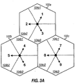
- FIG. 3A shows an exemplary subband assignment to achieve frequency orthogonality for a cluster with 3 cells, where each cell includes 3 sectors (i.e., a 9-sector 3-cell cluster).
- Each of the 9 sectors in the cluster is assigned one of 9 subband sets (which may be formed, for example, as shown in Table 2).
- the subband set assigned to each sector is indicated by the numeric reference next to the arrow in FIG. 3A .
- Each sector would then transmit its pilot on only the subbands in its assigned set.
- the 9 sectors in the cluster may simultaneously transmit their pilots on 9 disjoint sets of subbands while achieving orthogonality in the frequency domain and avoiding interference.
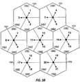
- FIG. 3B shows an exemplary subband assignment to achieve frequency orthogonality for a cluster with 7 cells, where each cell includes 3 sectors (i.e., a 21-sector 7-cell cluster). Each of the 21 sectors in the cluster is assigned one of 21 subband sets. The 21 sectors in the cluster may simultaneously transmit their pilots, on 21 disjoint sets of subbands while achieving orthogonality in the frequency domain and avoiding interference.
- a cluster may be defined to include any number of cells, and each cell may comprise any number of sectors.
- a cluster may be defined to include 1, 2, 3, 7, or 19 cells.
- the size of the cluster may be dependent on various factors, such as those enumerated above.
- Frequency orthogonality may also be achieved for a system that employs multiple antennas at each sector for pilot and data transmission to achieve spatial diversity and improve reliability.
- each sector may transmit data from two antennas using a space-time transmit diversity (STTD) scheme or an Alamouti scheme.
- STTD space-time transmit diversity
- Alamouti scheme is described in 3G TS 25.211 and in provisional U.S. Patent Application Serial No. 60/421,309 , entitled "MIMO WLAN System,” filed October 25, 2002, assigned to the assignee of the present application.
- the Alamouti scheme is described by S.M. Alamouti in a paper entitled "A Simple Transmit Diversity Technique for Wireless Communications," IEEE JSAC, Oct. 1998 .
- each antenna may be assigned a different subband set.
- Time orthogonality may be achieved by "covering" the pilot of each cell or sector with a different orthogonal code.
- the pilot from each cell/sector may be recovered by "decovering" the received signal with the same orthogonal code used by that cell/sector. Covering is a process whereby a given pilot or data symbol (or a set of Q pilot/data symbols with known values) to be transmitted is multiplied by all Q chips of a Q-chip orthogonal sequence to obtain Q covered symbols, which are further processed and then transmitted.
- Decovering is a complementary process whereby received symbols are multiplied by (a) the Q chips of the same Q-chip orthogonal sequence and (b) the complex conjugate of the pilot or data symbol (or the complex conjugate of the Q pilot/data symbols) to obtain Q decovered symbols, which are then accumulated to obtain an estimate of the transmitted pilot or data symbol. Covering and decovering are known in the art and also described below. The decovering removes or cancels the pilots transmitted by other cells/sectors that use different orthogonal codes for their pilots. In this way, orthogonality among the pilot transmissions from multiple cells/sectors may be achieved.
- the effectiveness of the pilot orthogonalization through covering is dependent on having the knowledge of the timing for the base stations. Time orthogonality may be achieved for sectors of the same cell since these sectors may be operated synchronously.
- the cells in each cluster or all cells in the system may also be operated synchronously to allow time orthogonality to be achieved for the pilots transmitted by these cells.
- Time orthogonality may be achieved with various types of orthogonal codes, such as Walsh codes and orthogonal variable spreading factor (OVSF) codes.
- the length of the orthogonal codes used for pilot covering is dependent on the number of orthogonal codes required, which in turn is dependent on the size of the cluster for which time orthogonality is to be achieved. For example, if time orthogonality is desired for a cell with 3 sectors, then 3 orthogonal codes are needed (i.e., one code for each sector) and each orthogonal code would then have a length of 4 chips.
- Table 3 lists four 4-chip Walsh codes that may be assigned to up to four different sectors, cells, or antennas.
- Table 3 Walsh Codes Values W 1 ( n ) 1 1 1 1 1 W 2 ( n ) 1 1 -1 -1 W 3 ( n ) 1 -1 1 -1 W 4 ( n ) 1 -1 -1 1
- a specific Walsh code may be assigned to each sector or each antenna of a given cell.
- a value of "-1" for the Walsh code may indicate an inversion of the pilot symbol (i.e., p k ( n ) ⁇ -p k ( n )) and a value of "1" may indicate no inversion.
- the same Walsh code may be applied to each of the subbands used for pilot transmission.
- the four chips of the Walsh code are applied to four pilot symbols to be transmitted in four consecutive OFDM symbol periods.
- a Walsh code is also referred to as a Walsh sequence or a Walsh symbol, and T w denotes one Walsh symbol period.
- FIG. 4A shows an exemplary orthogonal code assignment to achieve time orthogonality for a cell with three sectors (i.e., a 3-sector 1-cell cluster). Each of the three sectors in the cell is assigned a different orthogonal code. The three orthogonal codes assigned to the 3 sectors are labeled as A, B, and C. As indicated in FIG. 4A , the same subband set may be used by all three sectors in the cell. Orthogonality is then achieved in the time domain for the pilot transmissions from these three sectors via the use of different orthogonal codes.
- FIG. 4B shows an exemplary orthogonal code assignment to achieve time orthogonality for a cell with three sectors, with each sector employing two antennas for pilot and data transmission.
- Each of the three sectors in the cell is assigned two orthogonal codes, one code for each antenna.
- the three pairs of orthogonal codes assigned to the three sectors are labeled as A/B, C/D, and E/F.
- the 3-sector cell would then require a total of six orthogonal codes, and each orthogonal code may then have a length of 8 chips.
- the time orthogonality property may be degraded by temporal variations in the propagation paths between the base stations and the terminal.
- frequency orthogonality is achieved for multiple cells in a cluster
- time orthogonality is achieved for multiple sectors within each cell.
- FIG. 4C shows an exemplary subband and code assignment to achieve frequency and time orthogonality for a 9-sector 3-cell cluster.
- Each of the three cells in the cluster is assigned a different subband set to achieve frequency orthogonality among the three cells.
- the three sectors of each cell are also assigned three different orthogonal codes to achieve time orthogonality among the three sectors.
- Each sector of each cell would then transmit its pilot using its assigned orthogonal code and only on the subbands in the set assigned to its cell. Orthogonality is then achieved for the pilot transmissions from the nine sectors in this cluster and interference is avoided.
- FIG. 4D shows an exemplary subband and code assignment to achieve frequency and time orthogonality for a 21-sector 7-cell cluster.
- Each of the seven cells in the cluster is assigned a different subband set.
- the three sectors of each cell are also assigned different orthogonal codes.
- Each sector of each cell would then transmit its pilot using its assigned orthogonal code and only on the assigned subbands.
- Frequency and time orthogonality may also be achieved in some other manners, and this is within the scope of the invention.
- multiple cells may be assigned the same subband sets but different orthogonal codes.
- multiple subband sets may be assigned to multiple sectors of the same cell, and different cells in the cluster may be assigned different orthogonal codes.
- each cell is assigned one subband set, and each antenna in the cell is assigned a different orthogonal code. If each sector includes two antennas, then each sector may be assigned a pair of orthogonal codes, as shown in FIG. 4B .
- the multiple sectors of a cell are assigned different orthogonal codes, and the multiple antennas of each sector are assigned different subband sets. The same subband sets may be used for all sectors of the same cell, and antennas assigned with the same subband set are assigned different orthogonal codes.
- two subband sets (e.g., sets 1 and 2) may be assigned to the two antennas of each cell, and the three sectors may be assigned orthogonal codes A, B, and C.
- One sector of the cell may be assigned subband set/orthogonal code pairings of 1-A and 2-A
- the second sector may be assigned 1-B and 2-B
- the third sector may be assigned 1-C and 2-C.
- a scrambling code may be used to randomize pilot interference and to enable identification of the base station.
- a different scrambling code may be assigned to each sector, each cell, or each cluster.
- the scrambling code may be a pseudo-random number (PN) sequence or some other unique sequence.
- the scrambling code may be applied to the pilot in the frequency domain (e.g., before the orthogonal code covering), as described below.
- the scrambling code may also be applied in the time domain (e.g., after the OFDM processing), in which case the scrambling code rate should not be greater than the OFDM symbol rate to preserve frequency orthogonality.
- the complementary processing is then performed by the terminal to recover the pilot. The processing at the base station and terminal for scrambling and descrambling is described below.
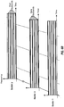
- FIG. 5 shows an exemplary system layout 500 whereby a different scrambling code is assigned to each 7-cell cluster.
- Each cluster in the layout is outlined by a thick solid line.
- One exemplary cluster is shown with seven shaded cells.
- the seven cells in each cluster are assigned different subband sets (which are labeled 1 through 7), and the three sectors in each cell are assigned different orthogonal codes (which are labeled A, B, and C).
- the pilot transmission from each sector in the layout can be identified by (1) the subband set assigned to the cell in which the sector belongs, (2) the orthogonal code assigned to the sector, and (3) the scrambling code assigned to the cluster in which the sector belongs.
- Other system layouts with different assignments of subbands, orthogonal codes, and scrambling codes may also be developed, and this is within the scope of the invention.
- the terminals in a given sector will receive pilot interference from only other sectors that are assigned with the same subband set and the same orthogonal code.
- the terminals in a sector labeled as 1-A will receive pilot interference from only other sectors labeled as 1-A in the layout.
- Each scrambling code S i ( n ) is a unique sequence of code chips, where n is the chip index for the sequence.
- each scrambling code chip is a complex value with the form s i ( n ) + j ⁇ i ( n )i , where s i ( n ) and ⁇ i ( n ) may each take on a value of either +1 or -1.
- the scrambling codes may be defined in some other manners, and with either real or complex values for the code chips.
- the scrambling may be performed in various manners, depending on the characteristics of the wireless channel.
- the channel should be essentially constant over the entire time duration in which each scrambling code chip is applied.
- the time interval over which the channel is essentially constant is often referred to as coherence time and may be denoted as ⁇ .
- each scrambling code chip may be applied to one orthogonal sequence of length T W .
- the same scrambling code chip may be applied to each of the K subbands used for pilot transmission.
- each scrambling code chip is applied to four Walsh code chips that are applied to four pilot symbols to be transmitted in four consecutive OFDM symbol periods.
- a terminal may perform orthogonal code decovering followed by scrambling code descrambling using the orthogonal code and scrambling code assigned to that sector.
- the terminal may also perform coherent integration over all or part of the scrambling sequence to recover the pilot and to discriminate "co-channel" sectors (i.e., sectors assigned with the same subband sets but different orthogonal codes and/or scrambling codes).
- Coherent integration refers to a process whereby multiple complex-valued symbols are combined in a manner to take into account their phase information.
- each scrambling code chip may be applied to one orthogonal code chip.
- the same or different scrambling code chips may be used for the K pilot subbands.
- the scrambling code may be defined with a length of 4 ⁇ K.
- the first K scrambling code chips may then be used for the K pilot subbands for the first Walsh code chip, the next K scrambling code chips may be used for the K pilot subbands for the second Walsh code chip, the next K scrambling code chips may be used for the K pilot subbands for the third Walsh code chip, and the last K scrambling code chips may be used for the K pilot subbands for the fourth and last Walsh code chip.
- the same scrambling sequence may be used by all base stations for which time orthogonality is to be achieved.
- the scrambling provides pilot interference randomization. Since the same scrambling sequence is used by multiple base stations, each base station may be identified by its assigned orthogonal code, possibly the scrambling code, and its assigned set of pilot subbands.
- a terminal may derive a pilot estimate for each pilot subband as described below.
- the receiver may then obtain (1) an estimate of the channel response for each of a number of pilot and data subbands based on the pilot estimates for all K pilot subbands and (2) an estimate of the received pilot power as the sum the squared magnitude of the pilot estimates for all K pilot subbands.
- the processing by the terminal for the pilot is described in further detail below.
- Pilots may be transmitted by the base stations on the downlink in various manners to facilitate both pilot detection and channel estimation. Pilot detection may be used to facilitate system synchronization (frequency and timing acquisition), hard handoff, and soft handoff. Channel estimation may be used to facilitate coherent data demodulation.
- Table 4 lists four exemplary pilot transmission schemes for multi-carrier communication systems. Table 4 System Timing Pilot Structure TDM Bursts Continuous Synchronous Synchronous burst pilot transmission scheme: pilots are transmitted in the same designated time intervals by all sectors in the system. Synchronous continuous pilot transmission scheme: each sector continuously transmits its pilot on a designated set of subbands based on system timing. Asynchronous Asynchronous burst pilot transmission scheme: pilots are transmitted by sectors in time intervals determined based on their individual timing. Asynchronous continuous pilot transmission scheme: each sector continuously transmits its pilot on a designated set of subbands based on its timing.
- each sector transmits its pilot in bursts in designated time intervals or slots (instead of continuously).
- Each sector may transmit pilot and data in a time division multiplex (TDM) manner.
- TDM time division multiplex
- each sector continuously transmits its pilot on its assigned set of pilot subbands.
- Each sector may transmit data on the remaining usable subbands not designated for pilot transmission.
- the timing of all sectors of all cells in the system is synchronized (e.g., based on GPS time or some other common timing source).
- the timing of all sectors of each cell may be synchronized, but the timing for different cells in the system is not synchronized.
- the sectors and cells in the system are synchronous and transmit their pilots in bursts in the same designated time slots.
- all sectors transmit their pilots at the same time, but the pilots are orthogonalized by the use of disjoint sets of pilot subbands and/or orthogonal codes.
- Data is not transmitted during periods of pilot transmission.
- a terminal may be able to obtain higher quality channel estimates for different sectors because no interference is received from data transmission.
- the channel estimate for a given sector may be further improved by canceling the interference from pilots transmitted on the same set of pilot subbands by other sectors, using pilot interference cancellation techniques described below.
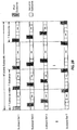
- FIG. 6A shows the transmission of pilots from multiple sectors for the synchronous burst pilot transmission scheme.
- the sectors transmit their pilots on disjoint sets of subbands in bursts of a particular time duration, T pilot , with a particular time spacing, T int , between bursts.
- T pilot time duration
- T int time spacing
- the timing of the sectors is synchronized such that the pilot bursts are approximately aligned at the time of their transmission.
- Each sector may transmit data in all usable subbands in the time period between pilot bursts. (For simplicity, frequency and time are not drawn to scale in FIGS. 6A and 6B .)
- the sectors and cells in the system are synchronous, and each sector continuously transmits its pilots on a designated set of pilot subbands.
- the pilots from different sectors may further be orthogonalized by the use of different orthogonal codes.
- data is not transmitted on the set of subbands designated for pilot transmission.
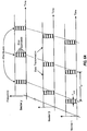
- FIG. 6B shows the transmission of pilots from multiple sectors for the synchronous continuous pilot transmission scheme.
- the sectors continuously transmit their pilots on disjoint sets of subbands.
- Each sector may transmit data on other subbands not designated for pilot transmission.
- the timing of the sectors is synchronized.
- the sectors in the system transmit their pilots in bursts in designated time slots and using disjoint sets of pilot subbands.
- the sectors within each cell may further orthogonalize their pilots by use of different orthogonal codes.
- the pilots from different cells may arrive at different times at a terminal, which would need to perform a search for these pilot bursts.
- the cells are not synchronized, data transmission from sectors in one cell can interfere with pilot transmission from sectors in other cells, and vice versa.
- each sector continuously transmits its pilots on a designated set of pilot subbands.
- the sectors within each cell may orthogonalize their pilots by use of different orthogonal codes. Because the cells are not synchronized, a terminal would need to determine the timing of each sector to be recovered.
- the pilot for each sector experiences minimum degradation from co-channel interference, i.e., interference from other sectors assigned with the same set of pilot subbands and orthogonal code.
- the pilot for each sector experiences degradation caused by co-channel interference due to data transmission on the pilot subbands by adjacent sectors.
- the pilot for each sector experiences degradation from co-channel interference due to data transmission plus inter-carrier interference caused by non-synchronous OFDM symbol timing, where the inter-carrier interference is not present in the absence of multipath.
- the pilot subbands may be assigned to the sectors in various manners.
- the set of subbands assigned to each sector for pilot transmission is fixed.
- each sector transmits its pilots on different sets of subbands at different time intervals. This embodiment may allow the terminals to obtain better estimates of the channel to the sector.
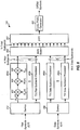
- FIG. 7 shows a block diagram of an embodiment of a base station 110x and a terminal 120x in multi-carrier communication system 100.
- base station 110x performs processing for one sector and includes one antenna.
- a transmit (TX) data processor 714 receives traffic data from a data source 712 and signaling and other data from a controller 730. TX data processor 714 formats, codes, interleaves, and modulates (i.e., symbol maps) the data to provide data modulation symbols, or simply data symbols.
- a modulator (MOD) 720 receives and multiplexes the data symbols with pilot symbols, performs the required processing, and provides a stream of OFDM symbols. The processing by modulator 720 is described below.
- a transmitter unit (TMTR) 722 then processes the OFDM symbol stream to provide a downlink signal, which is then transmitted from an antenna 724 to the terminals.
- the downlink signals transmitted by multiple base stations for multiple sectors are received by an antenna 752.
- the received signal is processed (e.g., amplified, filtered, frequency downconverted, and digitized) by a receiver unit (RCVR) 754 to provide samples.
- a demodulator (DEMOD) 760 then processes the samples in a manner complementary to that performed by modulator 720 to provide pilot strength estimates and data symbol estimates for the sector(s) being recovered.
- a receive (RX) data processor 762 further processes (e.g., symbol demaps, deinterleaves, and decodes) the data symbol estimates to provide decoded data, which may be provided to a data sink 764 for storage and/or a controller 770 for further processing.
- the processing for the uplink may be the same or different from the processing for the downlink.
- Data and signaling are processed (e.g., coded, interleaved, and modulated) by a TX data processor 784 to provide data symbols, which are multiplexed with pilot symbols and further processed by a modulator 790 to provide transmit symbols.
- Modulator 790 may perform OFDM processing, CDMA processing, and so on, depending on the particular modulation technique used for the uplink.
- a transmitter unit 792 further processes the transmit symbols to generate an uplink signal, which is then transmitted from antenna 752.
- the uplink signals from terminals are received by antenna 724, and the received signal is processed by a receiver unit 738 to provide samples.
- the samples are further processed by a demodulator 740 to provide data symbol estimates, which are further processed by an RX data processor 742 to provide decoded data for each terminal being recovered.
- the decoded data may be provided to a data sink 744 for storage and/or controller 730 for further processing.
- Controllers 730 and 770 control the operation of various processing units at the base station and terminal, respectively.
- Memory units 732 and 772 store data and program codes used by controllers 730 and 770, respectively.
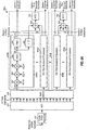
- FIG. 8 shows a block diagram of an embodiment of modulator 720.
- pilot transmission occurs on a set of K pilot subbands assigned to the i-th sector.
- the pilot symbols are covered with an N W -chip Walsh code W i ( n ) and scrambled with a scrambling code S i ( n ) that are assigned to the i -th sector.
- pilot symbol may be used for all pilot subbands or different pilot symbols may be used for different pilot subbands.
- a pilot symbol is a modulation symbol derived based on a particular modulation scheme (e.g., BPSK, QPSK, or M-QAM), i.e., a complex value corresponding to a point in a signal constellation for the modulation scheme.
- the same pilot symbols may be used by all sectors or different pilot symbols may be used by different sectors.
- a specific set of M pilot symbols is defined for the M usable subbands in the system. The pilot symbols used by each sector is then dependent on the set of pilot subbands assigned to that sector. Regardless, the terminals in the system have a priori knowledge of the pilot symbols used by the sectors in the system.
- the pilot symbols p i ( n ) to be transmitted by the i-th sector are provided to a demultiplexer (Demux) 812 and demultiplexed into K pilot symbol substreams for the K pilot subbands.
- the same pilot symbol may be transmitted on all K pilot subbands or a set of K pilot symbols may be transmitted on the K pilot subbands.
- each of the K pilot symbol substreams is provided to a respective TX pilot subband processor 820 that processes the pilot symbols for its assigned pilot subband.
- each TX pilot subband processor 820 the pilot symbols p i,k ( n ) for the assigned k -th pilot subband are provided to a complex multiplier 822 and multiplied with a scrambling code segment S i,k ( n ) for the k -th pilot subband.
- the scrambling may be performed in various manners.
- the scrambling may be such that each scrambling code chip is applied to (1) the entire Walsh sequence W i ( n ) for each of the K pilot subbands (for the first scrambling scheme described above), (2) one Walsh code chip in one pilot subband (for the second scrambling scheme described above), (3) one Walsh code chip for all K pilot subbands, or (4) some other combination of Walsh code chip(s) and pilot subband(s).
- the K segments of scrambling code chips used by the K TX pilot subband processors 820a through 820k may thus be the same or different depending on the particular scrambling scheme being implemented.
- the same scrambling code sequence is used for each of the K pilot subbands, and each scrambling code chip is applied to N W consecutive pilot symbols by maintaining the scrambling code chip constant for N W consecutive OFDM symbol periods.
- the scrambling sequence S i ( n ) is divided into K scrambling code segments (e.g., as described above for the second scrambling scheme), one segment for each of the K pilot subbands. Each scrambling code chip is then applied to one pilot symbol for one pilot subband.
- the scrambled pilot symbols from multiplier 822 are then provided to a multiplier 824 and covered with the Walsh code W i ( n ).
- the covered pilot symbols are then scaled by a multiplier 826 with a gain G pilot , which determines the amount of transmit power to use for pilot transmission.
- the total transmit power P total for each sector or each antenna is constrained, for example, by regulatory requirements and/or limitations of the power amplifier. A portion of this total transmit power P total is allocated for pilot transmission and the remaining power may be used for data transmission.
- the amount of power used for pilot transmission, P pilot may be selected to expedite pilot detection/ acquisition by the terminals in the sector while minimizing pilot interference to data transmission by other sectors.
- the pilot power P pilot may be fixed for variable, and the gain G pilot is determined based on the pilot power P pilot .
- the processed pilot symbols from the K TX pilot subband processors 820a through 820k are then provided to an M ⁇ N switch 848.
- the data symbols d i ( n ) to be transmitted by the i-th sector are provided to a demultiplexer 832 and demultiplexed into up to (M-K) data symbol substreams for the up to (M-K) subbands to be used for data transmission.
- Each data symbol is also a modulation symbol derived based on a particular modulation scheme (e.g., BPSK, QPSK, or M-QAM). The same or different modulation schemes may be used for the pilot and data symbols.
- Each data symbol substream is provided to a respective TX data subband processor 840 that processes the data symbols for the assigned data subband.
- Each processor 840 may perform Walsh covering, scrambling, scaling, some other processing, or no processing at all.
- the processed data symbols from the (M-K) data subband processors 840a through 840q are also provided to switch 848.
- Switch 848 orders the processed pilot symbols from K TX pilot subband processors 820 and the processed data symbols from (M-K) TX data subband processors 840 such that these symbols are provided to their designated pilot and data subbands. Switch 848 also provides a signal value of zero for each unused subband. For each OFDM symbol period, switch 848 provides to an inverse fast Fourier transform (IFFT) unit 850 a set of N output symbols (comprised of processed pilot and data symbols and zeros) for the N total subbands.
- IFFT inverse fast Fourier transform
- IFFT unit 850 the N symbols for each OFDM symbol period are transformed to the time domain using an inverse fast Fourier transform to obtain a "transformed" symbol that comprises N time-domain samples.
- a portion of each transformed symbol is repeated by a cyclic prefix generator 852 to form a corresponding OFDM symbol that comprises N+C p samples, where C p is the number of samples being repeated.
- the repeated portion is often referred to as a cyclic prefix.
- An OFDM symbol period corresponds to the duration of one OFDM symbol.
- Cyclic prefix generator 852 provides a stream of OFDM symbols for transmission over one antenna.
- the same pilot processing shown in FIG. 8 may be performed for each of the antennas.
- the pilot symbols for each antenna is covered with the Walsh code, scrambled with the scrambling code, and multiplexed onto the set of K pilot subbands assigned to that antenna.
- the same or different Walsh codes may be assigned to the multiple antennas, the same or different scrambling codes may be used for the antennas, and the same or different sets of subbands may be used for the antennas.
- the data symbols may be processed in accordance with the STTD or Alamouti scheme for transmission over multiple antennas, as described in the aforementioned provisional U.S. Patent Application Serial No. 60/421,309 .
- FIG. 9A shows a block diagram of an embodiment of a demodulator 760a, which may be used for the synchronous burst pilot transmission scheme described above whereby the sectors transmit their pilots in bursts at designated time slots. For each pilot burst, demodulator 760a may perform the processing to recover the pilots transmitted from multiple sectors.
- the received OFDM symbols are provided to a cyclic prefix removal unit 912, which removes the cyclic prefix appended to each OFDM symbol to obtain a corresponding received transformed symbol.
- An FFT unit 914 then transforms each received transformed symbol to the frequency domain to obtain N received symbols for the N total subbands.
- An N ⁇ M switch 916 provides the received symbols for each set of K pilot subbands to a respective set 918 of K RX pilot subband processors 920aa through 920ak, one processor 920 for each pilot subband in the set.
- pilots are received from multiple sectors on disjoint sets of subbands.
- a set of RX pilot subband processors may then be used to perform the pilot processing for each sector to be recovered. Since multiple sectors (e.g., from different cells or clusters) may transmit on the same subband set with different orthogonal codes, multiple sets of RX pilot subband processors may also be used to process a given set of pilot subbands. For simplicity, only one set of RX pilot subband processors is shown in FIG. 9A for each set of pilot subbands.
- the pilot processing by the terminal is complementary to the pilot processing performed by the sector and is further dependent on the characteristics of the channel. For improved pilot detection performance and better discrimination of the pilots transmitted by different sectors, it is desirable to perform coherent integration over as many OFDM symbol periods and as many pilot subbands as possible.
- the amount of coherent integration that may be performed in the time domain and the frequency domain is dependent on the coherence time and the coherence bandwidth, respectively, of the channel.
- the duration of coherent integration i.e., the number of OFDM symbols over which coherent integration may be performed
- the frequency span encompassing the subbands that may be coherently added should be less than the coherent bandwidth of the channel.
- the coherent bandwidth is the band in which the channel is essentially constant and is related to the delay spread of the channel.
- the pilot processing shown in FIG. 9A performs coherent integration over a single Walsh symbol period and a single pilot subband. For simplicity, the pilot processing for a given sector i is described below.
- the received symbols r k ( n ) for the assigned k -th pilot subband are provided to a multiplier 922 and multiplied with the Walsh code W i ( n ) for sector i.
- the decovered symbols are then provided to a complex multiplier 924 and multiplied with the complex conjugate of the scrambling code chips, S i , k ⁇ n , used for the k -th subband in the n -th OFDM symbol period by sector i.
- the descrambling is performed in a manner that is complementary to the scrambling performed by sector i.
- each scrambling code chip is applied to N W consecutive decovered symbols by maintaining the scrambling code chip constant for N W consecutive OFDM symbol periods.
- one scrambling code segment is used for each of the K pilot subbands, and each scrambling code chip is applied to one decovered symbol from multiplier 922 in one pilot subband.
- the descrambled symbols from multiplier 924 are then provided to a complex multiplier 926 and multiplied with the complex conjugate of the pilot symbols, p i , k ⁇ n , transmitted on the k -th subband in the n -th OFDM symbol period by sector i.
- the outputs from multiplier 926 are then accumulated over each Walsh symbol period by an accumulator (ACC) 928 to provide a pilot estimate p ⁇ i,k ( n ) for that Walsh symbol period.
- ACC accumulator
- Multipliers 922, 924, and 926 operate at the OFDM symbol rate (i.e., 1/T sym ).
- Accumulator 928 performs accumulation at the OFDM symbol rate, but provides a pilot estimate for each Walsh symbol period and is also cleared at the start of each Walsh symbol period.
- Filter 930 and unit 932 operate at the Walsh symbol rate (i.e., 1/T W , or 1/4T sym for 4-chip Walsh sequence).
- the pilot estimates p ⁇ i,k ( n ) from accumulator 928 may further be filtered by a filter 930 to provide an estimate ⁇ i,k ( n ) of the channel for the k -th pilot subband to sector i.
- Filter 930 may be implemented with an accumulator, a finite impulse response (FIR) filter, an infinite impulse response (IIR) filter, or some other type of filter.
- a unit 932 computes the squared magnitude of the pilot estimates p ⁇ i,k ( n ) from accumulator 928 to provide a pilot strength estimate
- a summer 934 receives and sums the pilot strength estimates
- An accumulator 938 then accumulates the pilot strength estimates
- Coherent integration may also be performed over multiple Walsh symbol periods, if permitted by the coherence time of the wireless channel.
- pilot estimates for multiple Walsh symbol periods may be accumulated (e.g., by accumulator 928), and the resultant estimate may be provided to filter 930 and unit 932.
- Coherent integration may also be performed over multiple pilot subbands (e.g., some or all K pilot subbands), if permitted by the coherence bandwidth of the wireless channel.
- pilot estimates from accumulator 928 for multiple pilot subbands may be accumulated (e.g., by another accumulator not shown in FIG. 9 ), magnitude squared, and provided to summer 934.
- the frequency span encompassing the pilot subbands over which coherent integration can be performed should be less than the coherence bandwidth of the wireless channel.
- Coherent integration in the frequency domain may be performed to obtain an improved pilot strength estimate, but the channel estimates are normally obtained for individual subbands.
- Coherent integration may also be performed over multiple Walsh symbol periods and multiple pilot subbands, if permitted by the coherence time and the coherence bandwidth of the wireless channel, to provide an improved pilot strength estimate.
- the pilot processing described above provides channel estimates for the K pilot subbands for sector i.
- Channel estimates for the remaining M - K subbands for sector i may be obtained based on (e.g., by interpolating) the channel estimates for the K pilot subbands sector i.
- a technique for estimating the channel estimates for all M subbands based on channel estimates for K subbands is described in U.S. Patent Application Serial No. 60/422,362 , entitled “Channel Estimation for OFDM Communication Systems," filed October 29, 2002, and U.S. Patent Application Serial No. 60/427,896 , entitled “Reduced Complexity Channel Estimation for Wireless Communication Systems,” filed November 19, 2002, both of which are assigned to the assignee of the present application.
- the channel estimates may be used for data demodulation and possibly other purposes.
- the channel estimates for all or a subset of the M usable subbands for sector i may be used to perform coherent data demodulation for a data transmission received from sector i. Channel estimates may also be obtained for multiple sectors in the systems. For each sector, the pilot processing is performed with the Walsh sequence W i ( n ), scrambling code S i ( n ), and pilot symbols p i ( n ) used by that sector.
- pilot processing described above also provides a pilot strength estimate for sector i. Pilot strength estimates may be obtained for multiple sectors in the systems. The pilot strength estimates for multiple sectors may be used to determine the best sector to receive data transmission, to hand off from one sector to another sector (e.g., for a mobile terminal), and possibly for other purposes.
- demodulator 760a performs pilot processing only during the time intervals when pilots are transmitted by the sectors.
- the channel estimates for one or multiple sectors may be used to perform coherent data demodulation of data transmission received from one or multiple sectors during the time period between pilot bursts.
- FIG. 9A shows an exemplary pilot processing technique that may be performed by the terminal.
- Other pilot processing techniques may also be used, and this is within the scope of the invention.
- only the pilot processing is shown for demodulator 760a in FIG. 9A .
- the data processing may be performed by demodulator 760a in the manner described below.
- FIG. 9B shows a block diagram of an embodiment of a demodulator 760b, which may be used for the synchronous continuous pilot transmission scheme described above whereby each sector continuously transmits its pilot in a designated set of pilot subbands and data on remaining subbands.
- demodulator 760b recovers the pilot and data transmitted by a given sector i.
- the received OFDM symbols are processed by cyclic prefix removal unit 912 and FFT unit 914 in the manner described above.
- Switch 916 then provides the received symbols for the K pilot subbands to K RX pilot subband processors 920a through 920k and the received symbols for M - K remaining subbands to M - K pilot interference cancellers 940a though 940q.
- Each RX pilot subband processors 920 performs the pilot processing for one pilot subband for sector i in the manner described above for FIG. 9A .
- the pilot subbands for sector i may be used as data subbands by other sectors, coherent integration may be performed over a longer time interval (e.g., multiple Walsh symbol periods) to cancel the interference due to data symbols from other sectors so that more accurate pilot estimates p ⁇ i,k ( n ) may be obtained.
- the coherent integration time interval is dictated by, and should be less than, the coherence time of the channel.
- multipliers 922, 924, and 926 operate at the OFDM symbol rate (i.e., 1/T sym ) and perform multiplication with the Walsh sequence W i ( n ), the scrambling code S i ( n ), and the pilot symbols p i ( n ) used by sector i.
- Accumulator 928 operates at the OFDM symbol rate and accumulates the outputs from multiplier 926 over one or (preferably) multiple Walsh symbol periods to provide a pilot estimate p ⁇ i,k ( n ) for each accumulation interval.
- Filter 930 operates at the accumulation rate and filters the pilot estimate p ⁇ i,k (n) to provide a channel estimate ⁇ i ( k ) for the k -subband of sector i.
- the channel estimates for all K pilot subbands may further be processed (e.g., interpolated) to obtain channel estimates for data subbands, as described above.
- Unit 932, summer 934, and accumulator 938 operate at the accumulation rate and provide a pilot strength estimate
- demodulator 760b may perform pilot processing at all times during a communication session.
- the channel estimates for sector i may be used to perform coherent data demodulation of a data transmission received on the data subbands from sector i.
- the data processing may be performed as described below.
- Demodulator 760b may also be designed with multiple sets of RX pilot subband processors and multiple sets of M - K pilot interference cancellers to concurrently process pilot and data transmissions from multiple sectors.
- Demodulators 760a and 760b may also be used to perform pilot processing for the asynchronous burst/continuous pilot transmission schemes described above. If the sectors are asynchronous, then the terminal would need to determine the timing of each sector to be recovered. This may be achieved by using a sliding correlator, similar to the one used for CDMA systems. The processing for each sector would then be performed in accordance with the timing of that sector. In particular, the FFT operation, decovering with the Walsh sequence W i ( n ), and descrambling with the scrambling code S i ( n ) are all performed in accordance with the timing for the sector to be recovered.
- coherent integration may be performed over a longer time period (e.g., multiple Walsh symbol periods) to cancel the interference due to data symbols transmitted by other sectors such that more accurate pilot estimates p ⁇ i,k ( n ) may be obtained for the sector to be recovered.
- the pilot processing for each sector may be performed (1) at time intervals when the pilot is transmitted by the sector and (2) based on the timing for that sector.
- the pilot processing for each sector may be performed at all times based on the timing for that sector.
- the pilot transmissions from the sectors in the system may be such that the subbands used for pilot transmission by a given sector i may also be used for pilot transmissions by other sectors.
- the pilot transmissions from other sectors on its pilot subbands represents interference that, if effectively canceled, can result in improved channel estimates and pilot strength estimate for sector i.
- the subbands used for data transmission by sector i may also be used for pilot transmissions by other sectors (e.g., for the continuous pilot transmission schemes).
- the pilot transmissions from other sectors on its data subbands represents interference that, if effectively canceled, can result in improved data performance.
- a terminal may be receiving data transmission from Sector 1 whose pilots are transmitted on subband set 1 (e.g., subbands 10, 20, 30, ... 500, for the exemplary OFDM system shown in Table 2 and FIG. 2B ).
- the terminal also has knowledge of the pilots transmitted by other sectors. Some of these other pilots will not be transmitted on subband set 1.
- a neighboring Sector 2 may transmit pilots on subband set 2 (e.g., subbands 11, 21, 31, ..., 501).
- Sector 1 transmits data to terminals in its coverage area using almost all of the usable subbands that are not in subband set 1. Therefore, the subbands in set 2 (which are used for pilot transmission by Sector 2) may be used as data subbands by Sector 1.
- the pilot transmission on the subbands in set 2 by Sector 2 will then act as interference to the data transmission on these same subbands by Sector 1.
- the terminal typically has knowledge of the pilot transmission on subband set 2 by Sector 2.
- the terminal can then estimate the pilot interference from Sector 2 on the subbands in set 2.
- the pilot interference estimates may be obtained by (1) estimating the channel from Sector 2 to the terminal for each of the subbands in set 2, (2) generating processed (i.e., scrambled and covered) pilot symbols for each subband in set 2 in the same manner as performed by Sector 2, and (3) scaling these processed pilot symbols with the channel estimate.
- the pilot interference estimate for each subband in set 2 for Sector 2 is then subtracted from the received symbols for the same subband to obtain the pilot-canceled symbols for that subband.
- pilot interference cancellation may be performed whenever subbands used for downlink pilot or data transmission by one sector are also used for downlink pilot transmission by another sector, with the pilot being known to the terminal.
- the terminal will have knowledge of the pilots transmitted by other sectors because this information is used to facilitate terminal-assisted handoff between the sectors.
- the terminal typically measures the power of the pilot received from its current serving sector and the pilots received from other nearby sectors that are candidates for handoff. The pilot power measurements may then be used by the terminal to request a handoff to a better serving sector.
- Pilot interference cancellation may be performed for a pilot subband to obtain a higher quality pilot estimate having interference due to pilots from other sectors removed. For example, for the synchronous burst pilot transmission scheme, all sectors transmit their pilots at the same time, in which case pilot interference cancellation may be performed to obtain improved channel estimates for a selected sector. Pilot interference cancellation may also be performed for a data subband to obtain a higher quality data symbol estimate having interference due to pilots from other sectors removed. For clarity, pilot interference cancellation is described below for a data subband.
- each canceller 940 estimates the pilot interference received by the terminal from each of the interfering sectors that have been designated for cancellation. Each canceller 940 then (1) obtains the total pilot interference estimates for all designated interfering sectors and (2) cancels the total pilot interference estimates from the received symbols to provide the pilot-canceled symbols for the assigned data subband.
- FIG. 10 shows a block diagram of an embodiment of pilot interference canceller 940x, which may be used for each of pilot interference cancellers 940a through 940q in FIG. 9 .
- the pilot interference cancellation is performed in the frequency domain, after the fast Fourier transform.
- Canceller 940x performs pilot interference cancellation for one data subband.
- each estimator 1020 estimates the pilot interference on an assigned k -th subband from an assigned j -th interfering sector and provides the pilot interference estimate p ⁇ j,k ( n ) for its assigned subband and sector.
- the received symbols r k ( n ) for the assigned k -th subband are provided to a multiplier 1022 and multiplied with the Walsh code W j ( n ) used by the j -th interfering sector.
- the output of multiplier 1022 is then multiplied by a complex multiplier 1024 with the complex conjugate of the scrambling code chips, S j , k ⁇ n , used for the k -th subband by the j -th interfering sector.
- the descrambled symbols from multiplier 1024 are then multiplied by a multiplier 1026 with the complex conjugate of the pilot symbols, p j , k ⁇ n , transmitted on the k -th subband by the j -th interfering sector.
- the outputs from multiplier 1026 are then accumulated over each Walsh symbol period by an accumulator 1028 to provide a pilot estimate p ⁇ j,k ( n ) for the k -th subband in that Walsh symbol period.
- the pilot estimates from accumulator 1028 are further filtered by a filter 1030 to provide a channel estimate ⁇ j,k ( n ) for the j -th interfering sector for the k -th subband.
- Filter 1030 may be implemented with an accumulator, a FIR filter, or an IIR filter.
- the response of filter 1030 (e.g., the duration of accumulation) may be dependent on the rate of channel fading.
- the pilot symbols p i,k ( n ) used by the j -th sector are (1) multiplied with the scrambling code chips S j,k ( n ) by a multiplier 1034, (2) covered with the Walsh code W j ( n ) by a multiplier 1036, and (3) multiplied with the channel estimate ⁇ j,k ( n ) by a multiplier 1038.
- the pilot interference estimates from all assigned estimators 1020 are then summed by a summer 1042 to obtain the total pilot interference estimates p ⁇ k ( n ) for the k -th subband.
- the total pilot interference estimates p ⁇ k ( n ) are then subtracted from the received symbols r k ( n ) by a summer 1044 to obtain the pilot-canceled symbols for the k -th subband.
- each processor 980 processes the pilot-canceled symbols for the assigned data subband in a manner that is complementary to that performed by processor 840 in FIG. 8 .
- Each processor 980 may also perform coherent data demodulation by computing a dot product of the pilot-canceled symbols with the channel estimate for the assigned data subband to provide data symbol estimates d ⁇ i,k ( n ), which are estimates of the data symbols transmitted on that subband.
- the channel estimates for the data subbands for the i -th sector being recovered may be derived based on the channel estimates obtained for the pilot subbands (e.g., using interpolation).
- a multiplexer 990 then receives and multiplexes the data symbol estimates from RX data subband processors 980a through 980q to provide the data symbol estimates d ⁇ i ( n ) for the i -th sector being recovered.
- the pilot interference cancellation technique described above may be straightforwardly extended to the case of multiple receive antennas at the terminal.
- the same pilot processing may be performed for the received signal obtained from each terminal antenna.
- the pilot-canceled symbols for each antenna may further be coherently demodulated with the channel estimate to provide data symbol estimates for that antenna.
- the data symbol estimates from all antennas may then be weighted and combined to provide the final data symbol estimates, which may then be decoded.
- pilot transmission and pilot interference cancellation techniques described herein may be implemented by various means.
- the processing for pilot transmission at the access point and the processing for pilot detection and pilot interference cancellation at the terminal may be implemented in hardware, software, or a combination thereof.
- the elements used to process the pilots for transmission/reception and for pilot interference cancellation may be implemented within one or more application specific integrated circuits (ASICs), digital signal processors (DSPs), digital signal processing devices (DSPDs), programmable logic devices (PLDs), field programmable gate arrays (FPGAs), processors, controllers, micro-controllers, microprocessors, other electronic units designed to perform the functions described herein, or a combination thereof.
- ASICs application specific integrated circuits
- DSPs digital signal processors
- DSPDs digital signal processing devices
- PLDs programmable logic devices
- FPGAs field programmable gate arrays
- processors controllers, micro-controllers, microprocessors, other electronic units designed to perform the functions described herein, or a combination thereof.
- the processing for pilot transmission/ reception and pilot interference cancellation may be implemented with modules (e.g., procedures, functions, and so on) that perform the functions described herein.
- the software codes may be stored in a memory unit (e.g., memory units 732 and 772 in FIG. 47 and executed by a processor (e.g., controllers 730 and 770).
- the memory unit may be implemented within the processor or external to the processor, in which case it can be communicatively coupled to the processor via various means as is known in the art.
Landscapes
- Engineering & Computer Science (AREA)
- Signal Processing (AREA)
- Computer Networks & Wireless Communication (AREA)
- Quality & Reliability (AREA)
- Physics & Mathematics (AREA)
- Mathematical Physics (AREA)
- Power Engineering (AREA)
- Mobile Radio Communication Systems (AREA)
Claims (11)
- Procédé de transmission d'un pilote sur une liaison descendante dans un système de communication multiporteuse sans fil (100), comprenant les étapes suivantes :la génération de symboles pilotes à transmettre sur un premier ensemble de sous-bandes, dans lequel le premier ensemble de sous-bandes est utilisé pour la transmission d'un pilote par une première entité émettrice et est disjoint d'un deuxième ensemble de sous-bandes utilisé pour la transmission d'un pilote par une deuxième entité émettrice, et dans lequel chaque paire de sous-bandes adjacentes du premier ensemble inclut une plage de fréquences qui est inférieure ou égale à une largeur de bande de cohérence d'un canal sans fil du système ;le traitement des symboles pilotes pour obtenir un signal pilote ayant les symboles pilotes inclus dans le premier ensemble de sous-bandes ; etla transmission du signal pilote à partir de la première entité émettrice.
- Procédé selon la revendication 1, comprenant en outre l'étape suivante :
le traitement des symboles pilotes avec un code orthogonal pour obtenir des symboles pilotes couverts, et dans lequel les symboles pilotes couverts sont en outre traités pour obtenir le signal pilote. - Procédé selon la revendication 1, comprenant en outre l'étape suivante :
le traitement des symboles pilotes avec un code de brouillage pour obtenir des symboles pilotes brouillés, et dans lequel les symboles pilotes brouillés sont en outre traités pour obtenir le signal pilote. - Procédé selon la revendication 1, dans lequel les sous-bandes du premier ensemble sont réparties uniformément parmi une pluralité de sous-bandes utilisables pour la transmission de pilotes et de données par la première entité émettrice.
- Procédé selon la revendication 1, dans lequel les signaux pilotes sont transmis en rafales à partir des première et deuxième entités émettrices.
- Procédé selon la revendication 1, dans lequel les signaux pilotes sont transmis avec une synchronisation synchrone à partir des première et deuxième entités émettrices.
- Procédé selon la revendication 1, dans lequel le système de communication multiporteuse met en œuvre un multiplexage par répartition en fréquence orthogonale (OFDM).
- Appareil (110) dans un système de communication multiporteuse sans fil (100), comprenant :des moyens (812, 820) pour générer des symboles pilotes à transmettre sur un premier ensemble de sous-bandes, dans lequel le premier ensemble de sous-bandes est utilisé pour la transmission d'un pilote par une première entité émettrice et est disjoint d'un deuxième ensemble de sous-bandes utilisé pour la transmission d'un pilote par une deuxième entité émettrice, et dans lequel chaque paire de sous-bandes adjacentes du premier ensemble inclut une plage de fréquences qui est inférieure ou égale à une largeur de bande de cohérence d'un canal sans fil du système ;des moyens (848) pour traiter les symboles pilotes pour obtenir un signal pilote ayant les symboles pilotes inclus dans le premier ensemble de sous-bandes ; etdes moyens (722) pour transmettre le signal pilote à partir de la première entité émettrice.
- Appareil selon la revendication 8, comprenant en outre :
des moyens (824) pour traiter les symboles pilotes avec un code orthogonal pour obtenir des symboles pilotes couverts, et dans lequel les symboles pilotes couverts sont en outre traités pour obtenir le signal pilote. - Appareil selon la revendication 8, comprenant en outre :
des moyens pour traiter les symboles pilotes avec un code de brouillage pour obtenir des symboles pilotes brouillés, et dans lequel les symboles pilotes brouillés sont en outre traités pour obtenir le signal pilote. - Support lisible par ordinateur destiné à transmettre un pilote sur une liaison descendante dans un système de communication multiporteuse sans fil, le support lisible par ordinateur comprenant des instructions qui, quand elles sont exécutées par un processeur, forcent ledit processeur à mettre en œuvre les étapes selon l'une quelconque des revendications 1 à 7.
Priority Applications (1)
| Application Number | Priority Date | Filing Date | Title |
|---|---|---|---|
| SI200432493T SI2282438T1 (sl) | 2003-01-07 | 2004-01-07 | Sheme prenosa pilotnega signala za brezžične komunikacijske sisteme z več nosilci |
Applications Claiming Priority (4)
| Application Number | Priority Date | Filing Date | Title |
|---|---|---|---|
| US43860103P | 2003-01-07 | 2003-01-07 | |
| US10/359,811 US7280467B2 (en) | 2003-01-07 | 2003-02-07 | Pilot transmission schemes for wireless multi-carrier communication systems |
| PCT/US2004/000326 WO2004064295A2 (fr) | 2003-01-07 | 2004-01-07 | Schema de transmission de pilotes pour systemes de telecommunications sans fil a porteuses multiples |
| EP04700634A EP1582042B1 (fr) | 2003-01-07 | 2004-01-07 | Schema de transmission de pilotes pour systemes de telecommunications sans fil a porteuses multiples |
Related Parent Applications (2)
| Application Number | Title | Priority Date | Filing Date |
|---|---|---|---|
| EP04700634.1 Division | 2004-01-07 | ||
| EP04700634A Division EP1582042B1 (fr) | 2003-01-07 | 2004-01-07 | Schema de transmission de pilotes pour systemes de telecommunications sans fil a porteuses multiples |
Publications (3)
| Publication Number | Publication Date |
|---|---|
| EP2282438A2 EP2282438A2 (fr) | 2011-02-09 |
| EP2282438A3 EP2282438A3 (fr) | 2012-04-25 |
| EP2282438B1 true EP2282438B1 (fr) | 2020-03-11 |
Family
ID=32684731
Family Applications (3)
| Application Number | Title | Priority Date | Filing Date |
|---|---|---|---|
| EP04700634A Expired - Lifetime EP1582042B1 (fr) | 2003-01-07 | 2004-01-07 | Schema de transmission de pilotes pour systemes de telecommunications sans fil a porteuses multiples |
| EP10012070.8A Expired - Lifetime EP2282436B1 (fr) | 2003-01-07 | 2004-01-07 | Schémas de transmission de pilote pour systèmes de communication multiporteur sans fil |
| EP10012069.0A Expired - Lifetime EP2282438B1 (fr) | 2003-01-07 | 2004-01-07 | Schémas de transmission de pilote pour systèmes de communication multiporteur sans fil |
Family Applications Before (2)
| Application Number | Title | Priority Date | Filing Date |
|---|---|---|---|
| EP04700634A Expired - Lifetime EP1582042B1 (fr) | 2003-01-07 | 2004-01-07 | Schema de transmission de pilotes pour systemes de telecommunications sans fil a porteuses multiples |
| EP10012070.8A Expired - Lifetime EP2282436B1 (fr) | 2003-01-07 | 2004-01-07 | Schémas de transmission de pilote pour systèmes de communication multiporteur sans fil |
Country Status (19)
| Country | Link |
|---|---|
| US (1) | US7280467B2 (fr) |
| EP (3) | EP1582042B1 (fr) |
| JP (3) | JP2006517759A (fr) |
| KR (1) | KR100978453B1 (fr) |
| AT (1) | ATE525839T1 (fr) |
| AU (2) | AU2004204911C1 (fr) |
| BR (1) | BRPI0406644A (fr) |
| CA (1) | CA2512551C (fr) |
| DK (1) | DK2282438T3 (fr) |
| ES (1) | ES2791527T3 (fr) |
| HK (1) | HK1086401A1 (fr) |
| HU (1) | HUE049055T2 (fr) |
| IL (1) | IL169509A0 (fr) |
| MX (1) | MXPA05007428A (fr) |
| PT (1) | PT2282438T (fr) |
| RU (2) | RU2507699C2 (fr) |
| SI (1) | SI2282438T1 (fr) |
| TW (1) | TWI324453B (fr) |
| WO (1) | WO2004064295A2 (fr) |
Families Citing this family (252)
| Publication number | Priority date | Publication date | Assignee | Title |
|---|---|---|---|---|
| US7295509B2 (en) * | 2000-09-13 | 2007-11-13 | Qualcomm, Incorporated | Signaling method in an OFDM multiple access system |
| US9130810B2 (en) | 2000-09-13 | 2015-09-08 | Qualcomm Incorporated | OFDM communications methods and apparatus |
| US6993333B2 (en) * | 2003-10-16 | 2006-01-31 | Flarion Technologies, Inc. | Methods and apparatus of improving inter-sector and/or inter-cell handoffs in a multi-carrier wireless communications system |
| US7002900B2 (en) | 2002-10-25 | 2006-02-21 | Qualcomm Incorporated | Transmit diversity processing for a multi-antenna communication system |
| US8320301B2 (en) | 2002-10-25 | 2012-11-27 | Qualcomm Incorporated | MIMO WLAN system |
| US8169944B2 (en) | 2002-10-25 | 2012-05-01 | Qualcomm Incorporated | Random access for wireless multiple-access communication systems |
| US7986742B2 (en) | 2002-10-25 | 2011-07-26 | Qualcomm Incorporated | Pilots for MIMO communication system |
| US8134976B2 (en) | 2002-10-25 | 2012-03-13 | Qualcomm Incorporated | Channel calibration for a time division duplexed communication system |
| US20040081131A1 (en) | 2002-10-25 | 2004-04-29 | Walton Jay Rod | OFDM communication system with multiple OFDM symbol sizes |
| US8208364B2 (en) | 2002-10-25 | 2012-06-26 | Qualcomm Incorporated | MIMO system with multiple spatial multiplexing modes |
| US8570988B2 (en) | 2002-10-25 | 2013-10-29 | Qualcomm Incorporated | Channel calibration for a time division duplexed communication system |
| US7042857B2 (en) | 2002-10-29 | 2006-05-09 | Qualcom, Incorporated | Uplink pilot and signaling transmission in wireless communication systems |
| US8400979B2 (en) * | 2003-01-07 | 2013-03-19 | Qualcomm Incorporated | Forward link handoff for wireless communication systems with OFDM forward link and CDMA reverse link |
| FR2851384B1 (fr) * | 2003-02-17 | 2009-12-18 | Wavecom | Procede de transmission de donnees radio, signal, systeme et dispositifs correspondant. |
| US7218948B2 (en) * | 2003-02-24 | 2007-05-15 | Qualcomm Incorporated | Method of transmitting pilot tones in a multi-sector cell, including null pilot tones, for generating channel quality indicators |
| US9544860B2 (en) | 2003-02-24 | 2017-01-10 | Qualcomm Incorporated | Pilot signals for use in multi-sector cells |
| US9661519B2 (en) | 2003-02-24 | 2017-05-23 | Qualcomm Incorporated | Efficient reporting of information in a wireless communication system |
| US7095790B2 (en) * | 2003-02-25 | 2006-08-22 | Qualcomm, Incorporated | Transmission schemes for multi-antenna communication systems utilizing multi-carrier modulation |
| US7177297B2 (en) * | 2003-05-12 | 2007-02-13 | Qualcomm Incorporated | Fast frequency hopping with a code division multiplexed pilot in an OFDMA system |
| JP2006527965A (ja) * | 2003-06-18 | 2006-12-07 | サムスン エレクトロニクス カンパニー リミテッド | 直交周波数分割多重方式を使用する通信システムにおける基地局の識別のためのパイロットパターンを送受信する装置及び方法 |
| KR100539948B1 (ko) * | 2003-06-18 | 2005-12-28 | 삼성전자주식회사 | 직교 주파수 분할 다중 방식을 사용하는 통신 시스템에서기지국 구분을 위한 파일럿 패턴 세트 송수신 장치 및 방법 |
| DE60337035D1 (de) * | 2003-07-29 | 2011-06-16 | Fujitsu Ltd | Pilot-Multiplex-Verfahren und Sendeeinrichtung für einem OFDM-System |
| KR100594597B1 (ko) * | 2003-10-24 | 2006-06-30 | 한국전자통신연구원 | 이동통신시스템에서의 하향링크 신호 구성 방법 및 그장치와, 이를 이용한 동기화 및 셀 탐색 방법과 그 장치 |
| KR100957415B1 (ko) | 2003-10-31 | 2010-05-11 | 삼성전자주식회사 | 직교 주파수 분할 다중 방식을 사용하는 통신 시스템에서 기지국 구분을 위한 파일럿 신호 송수신 장치 및 방법 |
| FI20031702A0 (fi) * | 2003-11-21 | 2003-11-21 | Nokia Corp | Useiden kantoaaltojen allokointi usealle käyttäjälle viestintäjärjestelmässä |
| US9473269B2 (en) | 2003-12-01 | 2016-10-18 | Qualcomm Incorporated | Method and apparatus for providing an efficient control channel structure in a wireless communication system |
| KR100856227B1 (ko) * | 2003-12-15 | 2008-09-03 | 삼성전자주식회사 | 이동통신시스템에서의 송/수신장치 및 방법 |
| TWI232041B (en) * | 2004-01-15 | 2005-05-01 | Accton Technology Corp | Multicarrier and multirate CDMA system |
| KR20050075242A (ko) * | 2004-01-16 | 2005-07-20 | 삼성전자주식회사 | 주파수 인터리빙 mc-cdma 시스템에서의 파일럿 채널기반의 채널추정방법 |
| US8611283B2 (en) | 2004-01-28 | 2013-12-17 | Qualcomm Incorporated | Method and apparatus of using a single channel to provide acknowledgement and assignment messages |
| EP1712019B1 (fr) | 2004-01-29 | 2014-01-15 | Neocific, Inc. | Procedes et appareil de superpositon de signaux multi-porteuses et a spectre etale a sequence directe dans un systeme de transmission sans fil a bande large |
| US7742533B2 (en) * | 2004-03-12 | 2010-06-22 | Kabushiki Kaisha Toshiba | OFDM signal transmission method and apparatus |
| KR100798968B1 (ko) * | 2004-03-13 | 2008-01-28 | 삼성전자주식회사 | 직교 분할 다중 접속 시스템에서 파일럿 신호 송수신 방법 및 장치 |
| US7545874B1 (en) * | 2004-04-05 | 2009-06-09 | National Semiconductor Corporation | Apparatus for pre-scaling data packets with multiple signal gain coefficients in a SIMO/MISO transceiver for communication with a SISO transceiver |
| KR100643740B1 (ko) * | 2004-04-09 | 2006-11-10 | 삼성전자주식회사 | 직교 주파수 분할 다중 방식을 사용하는 통신 시스템에서기지국 구분을 위한 파일럿 코드 패턴 송수신 장치 및 방법 |
| JP4447372B2 (ja) * | 2004-05-13 | 2010-04-07 | 株式会社エヌ・ティ・ティ・ドコモ | 無線通信システム、無線通信装置、無線受信装置、無線通信方法及びチャネル推定方法 |
| US9525977B2 (en) * | 2004-06-15 | 2016-12-20 | Texas Instruments Incorporated | Broadcast multicast mode |
| KR100744336B1 (ko) * | 2004-06-18 | 2007-07-30 | 삼성전자주식회사 | Ofdm기반의 무선 통신 시스템에서의 핸드오버 방법 |
| KR100739511B1 (ko) * | 2004-06-25 | 2007-07-13 | 삼성전자주식회사 | 직교 주파수 분할 다중 방식을 사용하는 통신 시스템에서파일럿 신호 송수신 장치 및 방법 |
| US7583586B2 (en) * | 2004-07-02 | 2009-09-01 | Samsung Electronics Co., Ltd | Apparatus and method for transmitting/receiving pilot signal in communication system using OFDM scheme |
| US20060009168A1 (en) * | 2004-07-12 | 2006-01-12 | Lucent Technologies, Inc. | Method for controlling transmissions using both diversity and nondiversity transmission schemes |
| US7430163B2 (en) * | 2004-07-19 | 2008-09-30 | Tzero Technologies, Inc. | Data stream transmission preprocessing |
| DE102004035018A1 (de) * | 2004-07-20 | 2006-02-16 | Siemens Ag | Verfahren zur Signalübertragung in einem Kommunikationssystem |
| US9148256B2 (en) | 2004-07-21 | 2015-09-29 | Qualcomm Incorporated | Performance based rank prediction for MIMO design |
| US9137822B2 (en) | 2004-07-21 | 2015-09-15 | Qualcomm Incorporated | Efficient signaling over access channel |
| US7372913B2 (en) * | 2004-07-22 | 2008-05-13 | Qualcomm Incorporated | Pilot tones in a multi-transmit OFDM system usable to capture transmitter diversity benefits |
| US8891349B2 (en) | 2004-07-23 | 2014-11-18 | Qualcomm Incorporated | Method of optimizing portions of a frame |
| CN100421365C (zh) * | 2004-08-14 | 2008-09-24 | 华为技术有限公司 | 实现用户设备无线资源控制的方法 |
| CN100352183C (zh) * | 2004-08-14 | 2007-11-28 | 华为技术有限公司 | 信道建立方法 |
| KR20060016053A (ko) * | 2004-08-16 | 2006-02-21 | 삼성전자주식회사 | 무선 통신 시스템에서 프리앰블 송수신 장치 및 방법 |
| US8484272B2 (en) * | 2004-08-20 | 2013-07-09 | Qualcomm Incorporated | Unified pulse shaping for multi-carrier and single-carrier waveforms |
| US7852746B2 (en) * | 2004-08-25 | 2010-12-14 | Qualcomm Incorporated | Transmission of signaling in an OFDM-based system |
| US7477633B2 (en) * | 2004-09-09 | 2009-01-13 | Agere Systems Inc. | Method and apparatus for varying the number of pilot tones in a multiple antenna communication system |
| KR100735231B1 (ko) * | 2004-11-11 | 2007-07-03 | 삼성전자주식회사 | 이동통신 시스템에서 파일럿 톤 배치 방법 및 장치 |
| US8571132B2 (en) * | 2004-12-22 | 2013-10-29 | Qualcomm Incorporated | Constrained hopping in wireless communication systems |
| US7852822B2 (en) * | 2004-12-22 | 2010-12-14 | Qualcomm Incorporated | Wide area and local network ID transmission for communication systems |
| US8238923B2 (en) | 2004-12-22 | 2012-08-07 | Qualcomm Incorporated | Method of using shared resources in a communication system |
| US8831115B2 (en) * | 2004-12-22 | 2014-09-09 | Qualcomm Incorporated | MC-CDMA multiplexing in an orthogonal uplink |
| EP1832075B1 (fr) | 2004-12-27 | 2016-03-09 | LG Electronics Inc. | Communication d'un signal detectable non coherent dans un systeme d'acces sans fil large bande |
| EP1699199B1 (fr) * | 2005-03-01 | 2007-11-28 | Alcatel Lucent | Procédé de transmission de données utilisant OFDM dans un réseau multicellulaire sans fil avec des pilotes pour l'estimation de canal, une station de base, un contrôleur de station de base et un réseau sans fil correspondants |
| KR100966069B1 (ko) * | 2005-03-01 | 2010-06-28 | 퀄컴 인코포레이티드 | 다중 송신 모드용 채널 추정 최적화 |
| US8135088B2 (en) * | 2005-03-07 | 2012-03-13 | Q1UALCOMM Incorporated | Pilot transmission and channel estimation for a communication system utilizing frequency division multiplexing |
| US7813383B2 (en) * | 2005-03-10 | 2010-10-12 | Qualcomm Incorporated | Method for transmission of time division multiplexed pilot symbols to aid channel estimation, time synchronization, and AGC bootstrapping in a multicast wireless system |
| US9246560B2 (en) | 2005-03-10 | 2016-01-26 | Qualcomm Incorporated | Systems and methods for beamforming and rate control in a multi-input multi-output communication systems |
| US9154211B2 (en) | 2005-03-11 | 2015-10-06 | Qualcomm Incorporated | Systems and methods for beamforming feedback in multi antenna communication systems |
| US8446892B2 (en) | 2005-03-16 | 2013-05-21 | Qualcomm Incorporated | Channel structures for a quasi-orthogonal multiple-access communication system |
| US9461859B2 (en) * | 2005-03-17 | 2016-10-04 | Qualcomm Incorporated | Pilot signal transmission for an orthogonal frequency division wireless communication system |
| US9143305B2 (en) * | 2005-03-17 | 2015-09-22 | Qualcomm Incorporated | Pilot signal transmission for an orthogonal frequency division wireless communication system |
| US9520972B2 (en) * | 2005-03-17 | 2016-12-13 | Qualcomm Incorporated | Pilot signal transmission for an orthogonal frequency division wireless communication system |
| US8160175B2 (en) * | 2005-03-29 | 2012-04-17 | Panasonic Corporation | Quasi-pilot symbol substitution |
| WO2006102771A1 (fr) | 2005-03-30 | 2006-10-05 | Nortel Networks Limited | Procedes et systemes de multiplexage frequentiel optique (ofdm) utilisant un multiplexage par repartition en code |
| JP2006311475A (ja) * | 2005-03-31 | 2006-11-09 | Ntt Docomo Inc | 制御装置、移動局および移動通信システム並びに制御方法 |
| US9184870B2 (en) | 2005-04-01 | 2015-11-10 | Qualcomm Incorporated | Systems and methods for control channel signaling |
| US9036538B2 (en) | 2005-04-19 | 2015-05-19 | Qualcomm Incorporated | Frequency hopping design for single carrier FDMA systems |
| US9408220B2 (en) | 2005-04-19 | 2016-08-02 | Qualcomm Incorporated | Channel quality reporting for adaptive sectorization |
| US8634432B2 (en) * | 2005-05-06 | 2014-01-21 | Samsung Electronics Co., Ltd. | System and method for subcarrier allocation in a multicarrier wireless network |
| US7466749B2 (en) | 2005-05-12 | 2008-12-16 | Qualcomm Incorporated | Rate selection with margin sharing |
| US7768979B2 (en) * | 2005-05-18 | 2010-08-03 | Qualcomm Incorporated | Separating pilot signatures in a frequency hopping OFDM system by selecting pilot symbols at least hop away from an edge of a hop region |
| EP1727297A1 (fr) * | 2005-05-25 | 2006-11-29 | Siemens Aktiengesellschaft | Procédé et terminal pour réduire l'interférence dans un système de radio communication |
| US8565194B2 (en) | 2005-10-27 | 2013-10-22 | Qualcomm Incorporated | Puncturing signaling channel for a wireless communication system |
| US8879511B2 (en) | 2005-10-27 | 2014-11-04 | Qualcomm Incorporated | Assignment acknowledgement for a wireless communication system |
| US8611284B2 (en) | 2005-05-31 | 2013-12-17 | Qualcomm Incorporated | Use of supplemental assignments to decrement resources |
| US8462859B2 (en) | 2005-06-01 | 2013-06-11 | Qualcomm Incorporated | Sphere decoding apparatus |
| US7554948B2 (en) * | 2005-06-07 | 2009-06-30 | Qualcomm, Incorporated | Reception of H-ARQ transmissions with interference cancellation in a quasi-orthogonal communication system |
| JP4440831B2 (ja) * | 2005-06-14 | 2010-03-24 | 株式会社エヌ・ティ・ティ・ドコモ | 基地局装置、送信方法及び通信システム |
| US9179319B2 (en) | 2005-06-16 | 2015-11-03 | Qualcomm Incorporated | Adaptive sectorization in cellular systems |
| KR100880991B1 (ko) * | 2005-06-16 | 2009-02-03 | 삼성전자주식회사 | 이동통신 시스템에서 다중 안테나를 이용한 파일럿 송수신장치 및 방법 |
| US8730877B2 (en) * | 2005-06-16 | 2014-05-20 | Qualcomm Incorporated | Pilot and data transmission in a quasi-orthogonal single-carrier frequency division multiple access system |
| US8599945B2 (en) | 2005-06-16 | 2013-12-03 | Qualcomm Incorporated | Robust rank prediction for a MIMO system |
| KR100953940B1 (ko) * | 2005-06-27 | 2010-04-22 | 삼성전자주식회사 | 직교 주파수 분할 다중화 시스템에서 소프트 핸드오버 영역의 단말을 위한 하향링크 데이터 송수신 방법 및 장치 |
| JP4546342B2 (ja) | 2005-07-07 | 2010-09-15 | パナソニック株式会社 | 送信装置および送信方法 |
| US7995664B2 (en) * | 2005-07-15 | 2011-08-09 | Lg Electronics Inc. | Method and apparatus for transmitting pilot symbols in wireless communication system |
| KR101108054B1 (ko) | 2005-07-15 | 2012-01-25 | 엘지전자 주식회사 | Mimo-ofdm 시스템에서의 전치부호 전송 방법 및데이터 전송 장치 |
| US8064424B2 (en) * | 2005-07-22 | 2011-11-22 | Qualcomm Incorporated | SDMA for WCDMA |
| US8014362B2 (en) * | 2005-07-28 | 2011-09-06 | Telecom Italia S.P.A. | Method for the assignment of scrambling codes to cells of a CDMA cellular mobile communications network |
| US8885628B2 (en) | 2005-08-08 | 2014-11-11 | Qualcomm Incorporated | Code division multiplexing in a single-carrier frequency division multiple access system |
| US8331216B2 (en) | 2005-08-09 | 2012-12-11 | Qualcomm Incorporated | Channel and interference estimation in single-carrier and multi-carrier frequency division multiple access systems |
| KR100965677B1 (ko) * | 2005-08-22 | 2010-06-24 | 삼성전자주식회사 | 다중반송파 방식을 사용하는 셀룰러 기반의 무선통신시스템에서의 자원할당 방법 및 할당된 자원을 수신하는방법 |
| US8611305B2 (en) | 2005-08-22 | 2013-12-17 | Qualcomm Incorporated | Interference cancellation for wireless communications |
| US8743909B2 (en) * | 2008-02-20 | 2014-06-03 | Qualcomm Incorporated | Frame termination |
| US8594252B2 (en) * | 2005-08-22 | 2013-11-26 | Qualcomm Incorporated | Interference cancellation for wireless communications |
| US8630602B2 (en) * | 2005-08-22 | 2014-01-14 | Qualcomm Incorporated | Pilot interference cancellation |
| US9209956B2 (en) | 2005-08-22 | 2015-12-08 | Qualcomm Incorporated | Segment sensitive scheduling |
| US9071344B2 (en) | 2005-08-22 | 2015-06-30 | Qualcomm Incorporated | Reverse link interference cancellation |
| US20070041457A1 (en) | 2005-08-22 | 2007-02-22 | Tamer Kadous | Method and apparatus for providing antenna diversity in a wireless communication system |
| WO2007023923A1 (fr) | 2005-08-24 | 2007-03-01 | Matsushita Electric Industrial Co., Ltd. | Dispositif de transmission mimo-ofdm et méthode de transmission mimo-ofdm |
| US8644292B2 (en) | 2005-08-24 | 2014-02-04 | Qualcomm Incorporated | Varied transmission time intervals for wireless communication system |
| US8355376B2 (en) * | 2005-08-25 | 2013-01-15 | Samsung Electronics Co., Ltd | Broadcast scheme for a multi-carrier wireless network |
| KR100729727B1 (ko) * | 2005-08-25 | 2007-06-18 | 한국전자통신연구원 | Ofdma 이동통신 시스템에서의 간섭을 제거하는 수신방법 및 장치 |
| US8855704B2 (en) | 2005-08-26 | 2014-10-07 | Qualcomm Incorporated | Fast cell selection in TD-CDMA (UMTS TDD) |
| US9136974B2 (en) | 2005-08-30 | 2015-09-15 | Qualcomm Incorporated | Precoding and SDMA support |
| US8139672B2 (en) | 2005-09-23 | 2012-03-20 | Qualcomm Incorporated | Method and apparatus for pilot communication in a multi-antenna wireless communication system |
| US20070071145A1 (en) * | 2005-09-23 | 2007-03-29 | Yona Perets | Method and apparatus to correct channel quality indicator estimation |
| US9191840B2 (en) | 2005-10-14 | 2015-11-17 | Qualcomm Incorporated | Methods and apparatus for determining, communicating and using information which can be used for interference control |
| US8694042B2 (en) * | 2005-10-14 | 2014-04-08 | Qualcomm Incorporated | Method and apparatus for determining a base station's transmission power budget |
| US9225488B2 (en) | 2005-10-27 | 2015-12-29 | Qualcomm Incorporated | Shared signaling channel |
| US9210651B2 (en) | 2005-10-27 | 2015-12-08 | Qualcomm Incorporated | Method and apparatus for bootstraping information in a communication system |
| US8068464B2 (en) * | 2005-10-27 | 2011-11-29 | Qualcomm Incorporated | Varying scrambling/OVSF codes within a TD-CDMA slot to overcome jamming effect by a dominant interferer |
| US9172453B2 (en) | 2005-10-27 | 2015-10-27 | Qualcomm Incorporated | Method and apparatus for pre-coding frequency division duplexing system |
| US8477684B2 (en) | 2005-10-27 | 2013-07-02 | Qualcomm Incorporated | Acknowledgement of control messages in a wireless communication system |
| US9144060B2 (en) | 2005-10-27 | 2015-09-22 | Qualcomm Incorporated | Resource allocation for shared signaling channels |
| US9225416B2 (en) | 2005-10-27 | 2015-12-29 | Qualcomm Incorporated | Varied signaling channels for a reverse link in a wireless communication system |
| US8130727B2 (en) * | 2005-10-27 | 2012-03-06 | Qualcomm Incorporated | Quasi-orthogonal allocation of codes in TD-CDMA systems |
| US8693405B2 (en) | 2005-10-27 | 2014-04-08 | Qualcomm Incorporated | SDMA resource management |
| US8582509B2 (en) | 2005-10-27 | 2013-11-12 | Qualcomm Incorporated | Scalable frequency band operation in wireless communication systems |
| US9088384B2 (en) * | 2005-10-27 | 2015-07-21 | Qualcomm Incorporated | Pilot symbol transmission in wireless communication systems |
| US8045512B2 (en) | 2005-10-27 | 2011-10-25 | Qualcomm Incorporated | Scalable frequency band operation in wireless communication systems |
| WO2007050843A2 (fr) * | 2005-10-27 | 2007-05-03 | Qualcomm Incorporated | Procede et dispositif d'attribution de ressources dans un systeme de communication sans fil |
| KR101259100B1 (ko) * | 2005-11-04 | 2013-04-26 | 엘지전자 주식회사 | Ofdm 또는 ofdma 무선 이동통신 시스템에서의초기 동기를 위한 신호 전송 방법, 초기 동기 획득 방법 및이동통신용 단말 |
| US20090219858A1 (en) * | 2005-11-07 | 2009-09-03 | Agency For Science, Technology And Research | Method and System for Transmitting a Signal to a Communication Device in a Cellular Communication System |
| JP4852551B2 (ja) * | 2005-11-16 | 2012-01-11 | シャープ株式会社 | マルチキャリア受信装置、マルチキャリア通信システムおよび復調方法 |
| US8582548B2 (en) * | 2005-11-18 | 2013-11-12 | Qualcomm Incorporated | Frequency division multiple access schemes for wireless communication |
| CN100449963C (zh) * | 2005-12-02 | 2009-01-07 | 华为技术有限公司 | 在辅载频上建立上行导频信道和快速物理接入信道的方法 |
| US20070149242A1 (en) * | 2005-12-03 | 2007-06-28 | Samsung Electronics Co., Ltd. | Method and apparatus for canceling neighbor cell interference signals in an orthogonal frequency division multiple access system |
| JP4991751B2 (ja) * | 2005-12-12 | 2012-08-01 | コーニンクレッカ フィリップス エレクトロニクス エヌ ヴィ | サブバンド毎の受信器アンテナ選択を伴うマルチバンドofdmシステムのためのシステム、装置、及び方法 |
| US8514771B2 (en) | 2005-12-22 | 2013-08-20 | Qualcomm Incorporated | Methods and apparatus for communicating and/or using transmission power information |
| US20070253449A1 (en) | 2005-12-22 | 2007-11-01 | Arnab Das | Methods and apparatus related to determining, communicating, and/or using delay information |
| US9125092B2 (en) | 2005-12-22 | 2015-09-01 | Qualcomm Incorporated | Methods and apparatus for reporting and/or using control information |
| US9137072B2 (en) | 2005-12-22 | 2015-09-15 | Qualcomm Incorporated | Methods and apparatus for communicating control information |
| US9473265B2 (en) | 2005-12-22 | 2016-10-18 | Qualcomm Incorporated | Methods and apparatus for communicating information utilizing a plurality of dictionaries |
| US8437251B2 (en) | 2005-12-22 | 2013-05-07 | Qualcomm Incorporated | Methods and apparatus for communicating transmission backlog information |
| US9148795B2 (en) | 2005-12-22 | 2015-09-29 | Qualcomm Incorporated | Methods and apparatus for flexible reporting of control information |
| US20070149132A1 (en) | 2005-12-22 | 2007-06-28 | Junyl Li | Methods and apparatus related to selecting control channel reporting formats |
| US9125093B2 (en) | 2005-12-22 | 2015-09-01 | Qualcomm Incorporated | Methods and apparatus related to custom control channel reporting formats |
| US9119220B2 (en) | 2005-12-22 | 2015-08-25 | Qualcomm Incorporated | Methods and apparatus for communicating backlog related information |
| US9338767B2 (en) | 2005-12-22 | 2016-05-10 | Qualcomm Incorporated | Methods and apparatus of implementing and/or using a dedicated control channel |
| US9572179B2 (en) | 2005-12-22 | 2017-02-14 | Qualcomm Incorporated | Methods and apparatus for communicating transmission backlog information |
| KR100872043B1 (ko) * | 2005-12-29 | 2008-12-05 | 삼성전자주식회사 | 광대역 무선접속 통신시스템에서 파일럿 패턴 결정 장치 및방법 |
| EP1806892A1 (fr) * | 2006-01-10 | 2007-07-11 | Alcatel Lucent | Procédé de séparation de signaux dans un système multiporteuse de télécommunication cellulaire |
| US8811369B2 (en) | 2006-01-11 | 2014-08-19 | Qualcomm Incorporated | Methods and apparatus for supporting multiple communications modes of operation |
| KR100979400B1 (ko) | 2006-01-11 | 2010-09-01 | 퀄컴 인코포레이티드 | 비콘 신호들의 부재 또는 존재 시에 사용되는 통신 방법 및장치 |
| CN101371545A (zh) * | 2006-01-12 | 2009-02-18 | 诺基亚公司 | 通信系统中的导频加扰 |
| JP4445474B2 (ja) * | 2006-01-16 | 2010-04-07 | 株式会社東芝 | Ofdm信号の送信方法、ofdm送信機及びofdm受信機 |
| JP4767700B2 (ja) * | 2006-01-17 | 2011-09-07 | 株式会社エヌ・ティ・ティ・ドコモ | 基地局および下りリンクチャネル送信方法 |
| US8130857B2 (en) * | 2006-01-20 | 2012-03-06 | Qualcomm Incorporated | Method and apparatus for pilot multiplexing in a wireless communication system |
| KR100913089B1 (ko) | 2006-02-07 | 2009-08-21 | 엘지전자 주식회사 | 다중 반송파 시스템에 적용되는 파일럿 신호 전송 방법 |
| KR101062674B1 (ko) | 2006-02-18 | 2011-09-06 | 삼성전자주식회사 | 무선 통신 시스템에서 자원을 할당하고 통신을 수행하는 장치 및 방법 |
| CA2866948C (fr) | 2006-02-28 | 2017-05-16 | Helvetia Ip Ag | Procedes et appareil pour le chevauchement de secteurs physiques d'une antenne mimo |
| US7782806B2 (en) | 2006-03-09 | 2010-08-24 | Qualcomm Incorporated | Timing synchronization and channel estimation at a transition between local and wide area waveforms using a designated TDM pilot |
| KR101285885B1 (ko) * | 2006-03-14 | 2013-07-11 | 엘지전자 주식회사 | 무선 통신 시스템에서 파일롯 심볼 전송 방법 및 장치 |
| EP1998484B1 (fr) * | 2006-03-20 | 2019-01-02 | Fujitsu Limited | Station de base et son procede de communication mimo-ofdm |
| US20070243882A1 (en) | 2006-04-12 | 2007-10-18 | Qualcomm Incorporated | Method and apparatus for locating a wireless local area network associated with a wireless wide area network |
| JP4736934B2 (ja) * | 2006-04-28 | 2011-07-27 | 日本電気株式会社 | 無線通信システム、パイロット系列割り当て装置及びそれらに用いるパイロット系列割り当て方法 |
| US8738056B2 (en) | 2006-05-22 | 2014-05-27 | Qualcomm Incorporation | Signal acquisition in a wireless communication system |
| ATE444633T1 (de) * | 2006-06-07 | 2009-10-15 | Mitsubishi Electric Corp | Multiträger system mit mehreren null-subträgern im sendesignal aufgrund der variablen empfangsbandbreite und der daraus resultierenden mehreren möglichen dc subträger |
| US8676209B2 (en) * | 2006-06-13 | 2014-03-18 | Qualcomm Incorporated | Handoff selection for wireless communication systems |
| DE602006002269D1 (de) * | 2006-06-13 | 2008-09-25 | Alcatel Lucent | Verfahren zum Zuteilen von Funkbetriebsmitteln eines zellularen Kommunikationsnetzwerks |
| US8929353B2 (en) * | 2007-05-09 | 2015-01-06 | Qualcomm Incorporated | Preamble structure and acquisition for a wireless communication system |
| BRPI0722368B1 (pt) * | 2006-06-16 | 2020-01-07 | Sharp Kabushiki Kaisha | Estação móvel |
| CN101438523A (zh) * | 2006-06-23 | 2009-05-20 | 松下电器产业株式会社 | 无线发送装置、无线接收装置以及导频生成方法 |
| JP4740065B2 (ja) * | 2006-08-22 | 2011-08-03 | 株式会社エヌ・ティ・ティ・ドコモ | 基地局、移動局及びパイロットチャネル生成方法 |
| GB0619530D0 (en) | 2006-10-03 | 2006-11-15 | Nokia Corp | Signalling |
| JP4444259B2 (ja) * | 2006-10-03 | 2010-03-31 | 株式会社エヌ・ティ・ティ・ドコモ | 下りリンクスクランブル方法および基地局装置 |
| WO2008069105A1 (fr) * | 2006-11-30 | 2008-06-12 | Panasonic Corporation | Dispositif de transmission radio, dispositif de réception radio, procédé de transmission radio et procédé de réception radio |
| JP5159274B2 (ja) * | 2006-11-30 | 2013-03-06 | パナソニック株式会社 | 無線送信装置及び無線送信方法 |
| CN101198087A (zh) * | 2006-12-08 | 2008-06-11 | 昂达博思公司 | 实现在移动通信系统中减少扇区间导频干扰的系统和方法 |
| KR101045180B1 (ko) * | 2006-12-08 | 2011-06-28 | 후지쯔 가부시끼가이샤 | 간섭 저감 방법 및 기지국 장치 |
| US7787358B2 (en) * | 2006-12-19 | 2010-08-31 | Telefonaktiebolaget Lm Ericsson (Publ) | Uplink inter-carrier interference cancellation of OFDMA systems |
| US20080144749A1 (en) * | 2006-12-19 | 2008-06-19 | Leif Wilhelmsson | Inter-Carrier Interference Cancellation for OFDMA Systems |
| US20080159448A1 (en) * | 2006-12-29 | 2008-07-03 | Texas Instruments, Incorporated | System and method for crosstalk cancellation |
| US20080159252A1 (en) * | 2006-12-29 | 2008-07-03 | Qi Bi | Method of coordinated transmission for broadcast-multicast services in high data rate networks |
| US8433357B2 (en) | 2007-01-04 | 2013-04-30 | Qualcomm Incorporated | Method and apparatus for utilizing other sector interference (OSI) indication |
| EP2122876B1 (fr) * | 2007-01-18 | 2016-04-06 | Apple Inc. | Procédé et appareil de réduction de probabilité de détection, d'amélioration de résistance au brouillage intentionnel et de sécurité pour systèmes sans fil en bande large |
| US8570955B2 (en) | 2007-03-08 | 2013-10-29 | Fujitsu Limited | Method of grouping and mapping transmission stations in a wireless network |
| US20080225689A1 (en) * | 2007-03-13 | 2008-09-18 | Bickerstaff Mark A | Orthogonal frequency division multiplexing having tones with overlaid data and pilot symbols |
| US8279743B2 (en) * | 2007-05-31 | 2012-10-02 | Telefonaktiebolaget Lm Ericsson (Publ) | Method for interference estimation for orthogonal pilot patterns |
| US7796698B2 (en) * | 2007-06-04 | 2010-09-14 | Telefonaktiebolaget Lm Ericsson (Publ) | Interference suppression in a multicarrier receiver |
| EP2003835A1 (fr) | 2007-06-15 | 2008-12-17 | Nokia Siemens Networks Oy | Procédé de fonctionnement d'un système de communication radio, station de récepteur et système de communication radio |
| US8543151B2 (en) | 2007-07-19 | 2013-09-24 | Samsung Electronics Co., Ltd. | Method for generating downlink frame, and method for searching cell |
| KR101495886B1 (ko) * | 2007-07-19 | 2015-02-26 | 한국전자통신연구원 | 하향링크 프레임 생성 방법 및 셀 탐색 방법 |
| US8665694B2 (en) * | 2007-08-14 | 2014-03-04 | Marvell World Trade Ltd. | Pilot design for universal frequency reuse in cellular orthogonal frequency-division multiplexing systems |
| US8289946B2 (en) * | 2007-08-14 | 2012-10-16 | Qualcomm Incorporated | Reference signal generation in a wireless communication system |
| EP2509267B1 (fr) * | 2007-08-15 | 2015-02-11 | Marvell World Trade Ltd. | Conception de pilote pour réutilisation de fréquence universelle dans les systèmes de multiplexage par répartition orthogonale de la fréquence cellulaire |
| US20090168730A1 (en) * | 2007-10-29 | 2009-07-02 | Motorola, Inc. | Pilot Signal Allocation Method and Apparatus |
| TWI351823B (en) * | 2008-03-04 | 2011-11-01 | Ind Tech Res Inst | Transmission architecture of transmitter |
| US20090225720A1 (en) * | 2008-03-10 | 2009-09-10 | Molisch Andreas F | Base Station Cooperation and Channel Estimation |
| EP3496492B1 (fr) | 2008-03-19 | 2020-04-22 | NEC Corporation | Système de communication sans fil, procédé de paramétrage de communication sans fil, station de base, station mobile et programme |
| TWI365650B (en) * | 2008-04-09 | 2012-06-01 | Ind Tech Res Inst | Transmission method of wireless signal and transmitter using the same |
| US20090257342A1 (en) * | 2008-04-10 | 2009-10-15 | Media Tek Inc. | Resource block based pilot pattern design for 1/2 - stream mimo ofdma systems |
| US8724718B2 (en) * | 2008-04-10 | 2014-05-13 | Mediatek Inc. | Pilot pattern design for small size resource block in OFDMA systems |
| CN101557371B (zh) * | 2008-04-10 | 2012-12-12 | 上海贝尔阿尔卡特股份有限公司 | 多载波mimo系统的基站中为移动终端确定导频图案的方法 |
| US8521206B2 (en) | 2008-04-22 | 2013-08-27 | Qualcomm Incorporated | Interference management with reduce interference requests and interference indicators |
| US8559879B2 (en) | 2008-04-22 | 2013-10-15 | Qualcomm Incorporated | Null pilots for interference estimation in a wireless communication network |
| US20090268910A1 (en) * | 2008-04-28 | 2009-10-29 | Samsung Electronics Co., Ltd. | Apparatus and method for initialization of a scrambling sequence for a downlink reference signal in a wireless network |
| TWI390875B (zh) * | 2008-05-05 | 2013-03-21 | Inst Information Industry | 基地台、下級站台及其傳輸方法 |
| US8107884B2 (en) * | 2008-05-05 | 2012-01-31 | Institute For Information Industry | Base station, subordinated station and transmission method thereof |
| US8595501B2 (en) | 2008-05-09 | 2013-11-26 | Qualcomm Incorporated | Network helper for authentication between a token and verifiers |
| US9408165B2 (en) * | 2008-06-09 | 2016-08-02 | Qualcomm Incorporated | Increasing capacity in wireless communications |
| CN101615928B (zh) * | 2008-06-25 | 2016-05-18 | 三星电子株式会社 | Lte系统中传输srs信令的方法和装置 |
| TWI382728B (zh) * | 2008-07-07 | 2013-01-11 | Inst Information Industry | 基地台、下級站台及其傳輸方法 |
| US9867203B2 (en) * | 2008-07-11 | 2018-01-09 | Qualcomm Incorporated | Synchronous TDM-based communication in dominant interference scenarios |
| US9237515B2 (en) | 2008-08-01 | 2016-01-12 | Qualcomm Incorporated | Successive detection and cancellation for cell pilot detection |
| US9277487B2 (en) | 2008-08-01 | 2016-03-01 | Qualcomm Incorporated | Cell detection with interference cancellation |
| KR101208549B1 (ko) | 2008-08-05 | 2012-12-05 | 엘지전자 주식회사 | 하향링크 mimo시스템에 있어서 기준 신호 송신 방법 |
| KR20110074555A (ko) * | 2008-09-22 | 2011-06-30 | 노오텔 네트웍스 리미티드 | Pucch의 공간 코드 송신 다양성을 위한 방법 및 시스템 |
| US20100080313A1 (en) * | 2008-09-30 | 2010-04-01 | Qualcomm Incorporated | Apparatus and method for supporting in-band venue-cast on a forward link only (flo) network using pilot interference cancellation |
| EP2342880B1 (fr) * | 2008-09-30 | 2014-04-02 | Telecom Italia S.p.A. | Procédé de transmission de signaux numériques, système de transmission correspondant et produit de programme d'ordinateur associés |
| EP2393317A1 (fr) * | 2009-01-30 | 2011-12-07 | Hitachi, Ltd. | Système de communication sans fil et procédé de commande de communication |
| US9094167B2 (en) * | 2009-02-02 | 2015-07-28 | Samsung Electronics Co., Ltd. | System and method for multi-user and multi-cell MIMO transmissions |
| WO2010089871A1 (fr) | 2009-02-05 | 2010-08-12 | 富士通株式会社 | Dispositif pour estimer un canal, procédé pour estimer un canal, station de base, et système de communication |
| US20100214938A1 (en) * | 2009-02-24 | 2010-08-26 | Qualcomm Incorporated | Flexible data and control multiplexing |
| US20100220651A1 (en) | 2009-03-02 | 2010-09-02 | Mediatek Inc. | Method and apparatus for broadcasting and receiving system information in OFDMA systems |
| US9160577B2 (en) | 2009-04-30 | 2015-10-13 | Qualcomm Incorporated | Hybrid SAIC receiver |
| US8787509B2 (en) | 2009-06-04 | 2014-07-22 | Qualcomm Incorporated | Iterative interference cancellation receiver |
| EP2504940B1 (fr) * | 2009-07-20 | 2018-08-29 | Commonwealth Scientific and Industrial Research Organisation | Communications de données sans fil |
| US8498273B2 (en) * | 2009-08-06 | 2013-07-30 | Telefonaktiebolaget L M Ericsson (Publ) | Management of uplink resources in multi-carrier CDMA system |
| WO2011022566A1 (fr) * | 2009-08-20 | 2011-02-24 | Alfred E. Mann Foundation For Scientific Research | Elimination optimale d'interférences à bande étroite pour des signaux séparés dans le temps |
| US8831149B2 (en) | 2009-09-03 | 2014-09-09 | Qualcomm Incorporated | Symbol estimation methods and apparatuses |
| CA2776454C (fr) | 2009-09-30 | 2016-07-05 | Interdigital Patent Holdings, Inc. | Procede et appareil d'emission multi-antenne de liaison montante |
| US8638682B2 (en) * | 2009-10-01 | 2014-01-28 | Qualcomm Incorporated | Method and apparatus for conducting measurements when multiple carriers are supported |
| CN102668612B (zh) | 2009-11-27 | 2016-03-02 | 高通股份有限公司 | 增加无线通信中的容量 |
| BR112012012632B1 (pt) | 2009-11-27 | 2020-12-15 | Qualcomm Incorporated | Método e equipamento para aumentar a capacidade de transmissão em comunicações sem fio, e memória legível por computador |
| US9609536B2 (en) | 2010-04-13 | 2017-03-28 | Qualcomm Incorporated | Measurement of received power and received quality in a wireless communication network |
| KR20120047449A (ko) * | 2010-11-04 | 2012-05-14 | 삼성전자주식회사 | 가중치를 고려하는 피아이씨 채널 추정기를 위한 방법 및 장치 |
| FR2967854A1 (fr) * | 2010-11-19 | 2012-05-25 | France Telecom | Procede de communication dans un reseau cooperatif |
| US8717887B2 (en) * | 2011-08-08 | 2014-05-06 | Telefonaktiebolaget Lm Ericsson (Publ) | Scrambling code planning device and method for using same in wireless communication network |
| WO2013038047A1 (fr) * | 2011-09-14 | 2013-03-21 | Nokia Corporation | Système, appareil, dispositif, programme informatique et procédé destinés à des dispositifs dotés de capacités de communication à courte portée |
| US8934398B2 (en) * | 2011-10-07 | 2015-01-13 | Qualcomm Incorporated | System, apparatus, and method for repeater pilot signal generation in wireless communication systems |
| US9603035B2 (en) | 2011-10-13 | 2017-03-21 | Telefonaktiebolaget L M Ericsson | Method and node related to channel estimation |
| JP5340448B2 (ja) * | 2012-04-10 | 2013-11-13 | パナソニック株式会社 | 送信装置および送信方法 |
| JP2015207816A (ja) * | 2014-04-17 | 2015-11-19 | 富士通株式会社 | 受信装置、受信方法、及び、無線通信システム |
| US10003480B2 (en) | 2014-05-29 | 2018-06-19 | Qualcomm Incorporated | Asynchronous multicarrier communications |
| CN111628854A (zh) | 2014-08-07 | 2020-09-04 | 相干逻辑公司 | 多分区无线电帧 |
| KR102302600B1 (ko) | 2014-08-07 | 2021-09-15 | 원 미디어, 엘엘씨 | 유연한 직교 주파수 분할 멀티플렉싱 물리 전송 데이터 프레임의 동적 구성 방법 |
| US10342012B2 (en) | 2015-03-15 | 2019-07-02 | Qualcomm Incorporated | Self-contained time division duplex (TDD) subframe structure |
| US9936519B2 (en) | 2015-03-15 | 2018-04-03 | Qualcomm Incorporated | Self-contained time division duplex (TDD) subframe structure for wireless communications |
| TWI575901B (zh) * | 2015-06-17 | 2017-03-21 | 晨星半導體股份有限公司 | 通道效應消除裝置及通道效應消除方法 |
| US9992790B2 (en) | 2015-07-20 | 2018-06-05 | Qualcomm Incorporated | Time division duplex (TDD) subframe structure supporting single and multiple interlace modes |
| US10461891B2 (en) * | 2015-12-18 | 2019-10-29 | Qualcomm Incorporated | Staggered pilot placement |
| US10285174B2 (en) | 2016-01-11 | 2019-05-07 | Qualcomm Incorporated | Uplink data channel design for narrowband devices |
| WO2018091082A1 (fr) * | 2016-11-16 | 2018-05-24 | Huawei Technologies Duesseldorf Gmbh | Dispositif radioélectrique et cellule radioélectrique à séquences de données multiplexées à attribution de puissance inégale |
| US9876657B1 (en) * | 2017-03-06 | 2018-01-23 | Xilinx, Inc. | System and method for downlink processing in communication systems |
Family Cites Families (25)
| Publication number | Priority date | Publication date | Assignee | Title |
|---|---|---|---|---|
| JP2873320B2 (ja) * | 1989-09-19 | 1999-03-24 | 日本電信電話株式会社 | 移動局の在圏セクタ判定方式 |
| IL100213A (en) * | 1990-12-07 | 1995-03-30 | Qualcomm Inc | Mikrata Kedma phone system and its antenna distribution system |
| US5483667A (en) * | 1993-07-08 | 1996-01-09 | Northern Telecom Limited | Frequency plan for a cellular network |
| US5418813A (en) * | 1993-12-06 | 1995-05-23 | Motorola, Inc. | Method and apparatus for creating a composite waveform |
| JPH09266466A (ja) * | 1996-03-28 | 1997-10-07 | Sumitomo Electric Ind Ltd | デジタル伝送システム |
| JPH09327073A (ja) * | 1996-06-07 | 1997-12-16 | N T T Ido Tsushinmo Kk | Cdma移動通信システムにおけるパイロットチャネル配置および送信方法 |
| JPH1028077A (ja) * | 1996-07-11 | 1998-01-27 | Takuro Sato | 通信装置 |
| US6067292A (en) * | 1996-08-20 | 2000-05-23 | Lucent Technologies Inc | Pilot interference cancellation for a coherent wireless code division multiple access receiver |
| US5867478A (en) * | 1997-06-20 | 1999-02-02 | Motorola, Inc. | Synchronous coherent orthogonal frequency division multiplexing system, method, software and device |
| BR9812816A (pt) * | 1997-09-15 | 2000-08-08 | Adaptive Telecom Inc | Processos para comunicação sem fio, e para eficientemente determinar na estação base um canal espacial da unidade móvel em um sistema de comunicação sem fio, e, estação base de cdma |
| US6175588B1 (en) * | 1997-12-30 | 2001-01-16 | Motorola, Inc. | Communication device and method for interference suppression using adaptive equalization in a spread spectrum communication system |
| JP2000092009A (ja) * | 1998-07-13 | 2000-03-31 | Sony Corp | 通信方法、送信機及び受信機 |
| US6385264B1 (en) * | 1999-06-08 | 2002-05-07 | Qualcomm Incorporated | Method and apparatus for mitigating interference between base stations in a wideband CDMA system |
| US6721339B2 (en) * | 1999-08-17 | 2004-04-13 | Lucent Technologies Inc. | Method of providing downlink transmit diversity |
| US6473467B1 (en) | 2000-03-22 | 2002-10-29 | Qualcomm Incorporated | Method and apparatus for measuring reporting channel state information in a high efficiency, high performance communications system |
| US6628702B1 (en) * | 2000-06-14 | 2003-09-30 | Qualcomm, Incorporated | Method and apparatus for demodulating signals processed in a transmit diversity mode |
| KR100627188B1 (ko) * | 2000-07-04 | 2006-09-22 | 에스케이 텔레콤주식회사 | 무선통신 역방향 동기 방식에서의 코드 할당 방법 |
| DE60035683T2 (de) * | 2000-08-01 | 2008-06-26 | Sony Deutschland Gmbh | Frequenzwiederverwendungsschema für OFDM-Systeme |
| KR100526499B1 (ko) | 2000-08-22 | 2005-11-08 | 삼성전자주식회사 | 두 개 이상 안테나를 사용하는 안테나 전송 다이버시티방법 및 장치 |
| JP3886709B2 (ja) * | 2000-08-29 | 2007-02-28 | 三菱電機株式会社 | スペクトル拡散受信装置 |
| JP2002077098A (ja) * | 2000-09-01 | 2002-03-15 | Mitsubishi Electric Corp | 通信装置および通信方法 |
| JP3553038B2 (ja) * | 2000-11-06 | 2004-08-11 | 株式会社エヌ・ティ・ティ・ドコモ | 信号送信方法、信号受信方法、送信装置、受信装置および記録媒体 |
| JP3695316B2 (ja) * | 2000-11-24 | 2005-09-14 | 株式会社日本自動車部品総合研究所 | スペクトラム拡散受信機の相関検出器 |
| AU2002240506A1 (en) | 2001-02-26 | 2002-09-12 | Magnolia Broadband, Inc | Smart antenna based spectrum multiplexing using a pilot signal |
| US7773699B2 (en) | 2001-10-17 | 2010-08-10 | Nortel Networks Limited | Method and apparatus for channel quality measurements |
-
2003
- 2003-02-07 US US10/359,811 patent/US7280467B2/en active Active
-
2004
- 2004-01-06 TW TW093100242A patent/TWI324453B/zh not_active IP Right Cessation
- 2004-01-07 RU RU2009131564/08A patent/RU2507699C2/ru active
- 2004-01-07 SI SI200432493T patent/SI2282438T1/sl unknown
- 2004-01-07 HU HUE10012069A patent/HUE049055T2/hu unknown
- 2004-01-07 JP JP2006500830A patent/JP2006517759A/ja not_active Withdrawn
- 2004-01-07 RU RU2005125045/09A patent/RU2368088C2/ru active
- 2004-01-07 BR BR0406644-8A patent/BRPI0406644A/pt not_active IP Right Cessation
- 2004-01-07 EP EP04700634A patent/EP1582042B1/fr not_active Expired - Lifetime
- 2004-01-07 WO PCT/US2004/000326 patent/WO2004064295A2/fr active Application Filing
- 2004-01-07 EP EP10012070.8A patent/EP2282436B1/fr not_active Expired - Lifetime
- 2004-01-07 KR KR1020057012744A patent/KR100978453B1/ko active IP Right Grant
- 2004-01-07 AU AU2004204911A patent/AU2004204911C1/en not_active Ceased
- 2004-01-07 PT PT100120690T patent/PT2282438T/pt unknown
- 2004-01-07 CA CA2512551A patent/CA2512551C/fr not_active Expired - Lifetime
- 2004-01-07 ES ES10012069T patent/ES2791527T3/es not_active Expired - Lifetime
- 2004-01-07 MX MXPA05007428A patent/MXPA05007428A/es active IP Right Grant
- 2004-01-07 DK DK10012069.0T patent/DK2282438T3/da active
- 2004-01-07 EP EP10012069.0A patent/EP2282438B1/fr not_active Expired - Lifetime
- 2004-01-07 AT AT04700634T patent/ATE525839T1/de not_active IP Right Cessation
-
2005
- 2005-07-03 IL IL169509A patent/IL169509A0/en unknown
-
2006
- 2006-05-26 HK HK06106133.9A patent/HK1086401A1/xx not_active IP Right Cessation
-
2009
- 2009-09-03 AU AU2009212939A patent/AU2009212939A1/en not_active Abandoned
-
2010
- 2010-11-15 JP JP2010254736A patent/JP5341052B2/ja not_active Expired - Lifetime
-
2013
- 2013-05-07 JP JP2013097793A patent/JP5755679B2/ja not_active Expired - Lifetime
Non-Patent Citations (1)
| Title |
|---|
| None * |
Also Published As
Similar Documents
| Publication | Publication Date | Title |
|---|---|---|
| EP2282438B1 (fr) | Schémas de transmission de pilote pour systèmes de communication multiporteur sans fil | |
| US7177297B2 (en) | Fast frequency hopping with a code division multiplexed pilot in an OFDMA system | |
| EP1625665B1 (fr) | Transfert souple avec annulation de brouillage dans un système de communications sans fil à saut de fréquence | |
| ZA200509154B (en) | Fast frequency hopping with a code division multiplexed pilot in an OFDMA system | |
| CN1751489B (zh) | 无线多载波通信系统的导频传输方案 | |
| ZA200509078B (en) | Soft handoff with interference cancellation in a wireless frequently hopping communication system |
Legal Events
| Date | Code | Title | Description |
|---|---|---|---|
| PUAI | Public reference made under article 153(3) epc to a published international application that has entered the european phase |
Free format text: ORIGINAL CODE: 0009012 |
|
| 17P | Request for examination filed |
Effective date: 20100930 |
|
| AC | Divisional application: reference to earlier application |
Ref document number: 1582042 Country of ref document: EP Kind code of ref document: P |
|
| AK | Designated contracting states |
Kind code of ref document: A2 Designated state(s): AT BE BG CH CY CZ DE DK EE ES FI FR GB GR HU IE IT LI LU MC NL PT RO SE SI SK TR |
|
| RIC1 | Information provided on ipc code assigned before grant |
Ipc: H04L 5/00 20060101AFI20111130BHEP |
|
| PUAL | Search report despatched |
Free format text: ORIGINAL CODE: 0009013 |
|
| AK | Designated contracting states |
Kind code of ref document: A3 Designated state(s): AT BE BG CH CY CZ DE DK EE ES FI FR GB GR HU IE IT LI LU MC NL PT RO SE SI SK TR |
|
| RIC1 | Information provided on ipc code assigned before grant |
Ipc: H04L 5/00 20060101AFI20120319BHEP |
|
| STAA | Information on the status of an ep patent application or granted ep patent |
Free format text: STATUS: EXAMINATION IS IN PROGRESS |
|
| 17Q | First examination report despatched |
Effective date: 20170626 |
|
| GRAP | Despatch of communication of intention to grant a patent |
Free format text: ORIGINAL CODE: EPIDOSNIGR1 |
|
| STAA | Information on the status of an ep patent application or granted ep patent |
Free format text: STATUS: GRANT OF PATENT IS INTENDED |
|
| INTG | Intention to grant announced |
Effective date: 20190925 |
|
| GRAS | Grant fee paid |
Free format text: ORIGINAL CODE: EPIDOSNIGR3 |
|
| GRAA | (expected) grant |
Free format text: ORIGINAL CODE: 0009210 |
|
| STAA | Information on the status of an ep patent application or granted ep patent |
Free format text: STATUS: THE PATENT HAS BEEN GRANTED |
|
| AC | Divisional application: reference to earlier application |
Ref document number: 1582042 Country of ref document: EP Kind code of ref document: P |
|
| AK | Designated contracting states |
Kind code of ref document: B1 Designated state(s): AT BE BG CH CY CZ DE DK EE ES FI FR GB GR HU IE IT LI LU MC NL PT RO SE SI SK TR |
|
| REG | Reference to a national code |
Ref country code: GB Ref legal event code: FG4D |
|
| REG | Reference to a national code |
Ref country code: CH Ref legal event code: EP |
|
| REG | Reference to a national code |
Ref country code: AT Ref legal event code: REF Ref document number: 1244495 Country of ref document: AT Kind code of ref document: T Effective date: 20200315 |
|
| REG | Reference to a national code |
Ref country code: IE Ref legal event code: FG4D |
|
| REG | Reference to a national code |
Ref country code: DE Ref legal event code: R096 Ref document number: 602004054555 Country of ref document: DE Ref country code: RO Ref legal event code: EPE |
|
| REG | Reference to a national code |
Ref country code: FI Ref legal event code: FGE |
|
| REG | Reference to a national code |
Ref country code: DK Ref legal event code: T3 Effective date: 20200407 |
|
| REG | Reference to a national code |
Ref country code: SE Ref legal event code: TRGR |
|
| REG | Reference to a national code |
Ref country code: PT Ref legal event code: SC4A Ref document number: 2282438 Country of ref document: PT Date of ref document: 20200511 Kind code of ref document: T Free format text: AVAILABILITY OF NATIONAL TRANSLATION Effective date: 20200505 |
|
| REG | Reference to a national code |
Ref country code: NL Ref legal event code: FP |
|
| REG | Reference to a national code |
Ref country code: GR Ref legal event code: EP Ref document number: 20200401168 Country of ref document: GR Effective date: 20200615 |
|
| REG | Reference to a national code |
Ref country code: HU Ref legal event code: AG4A Ref document number: E049055 Country of ref document: HU |
|
| PG25 | Lapsed in a contracting state [announced via postgrant information from national office to epo] |
Ref country code: BG Free format text: LAPSE BECAUSE OF FAILURE TO SUBMIT A TRANSLATION OF THE DESCRIPTION OR TO PAY THE FEE WITHIN THE PRESCRIBED TIME-LIMIT Effective date: 20200611 |
|
| PG25 | Lapsed in a contracting state [announced via postgrant information from national office to epo] |
Ref country code: SK Free format text: LAPSE BECAUSE OF FAILURE TO SUBMIT A TRANSLATION OF THE DESCRIPTION OR TO PAY THE FEE WITHIN THE PRESCRIBED TIME-LIMIT Effective date: 20200311 Ref country code: EE Free format text: LAPSE BECAUSE OF FAILURE TO SUBMIT A TRANSLATION OF THE DESCRIPTION OR TO PAY THE FEE WITHIN THE PRESCRIBED TIME-LIMIT Effective date: 20200311 |
|
| REG | Reference to a national code |
Ref country code: ES Ref legal event code: FG2A Ref document number: 2791527 Country of ref document: ES Kind code of ref document: T3 Effective date: 20201104 |
|
| REG | Reference to a national code |
Ref country code: DE Ref legal event code: R097 Ref document number: 602004054555 Country of ref document: DE |
|
| PLBE | No opposition filed within time limit |
Free format text: ORIGINAL CODE: 0009261 |
|
| STAA | Information on the status of an ep patent application or granted ep patent |
Free format text: STATUS: NO OPPOSITION FILED WITHIN TIME LIMIT |
|
| 26N | No opposition filed |
Effective date: 20201214 |
|
| PG25 | Lapsed in a contracting state [announced via postgrant information from national office to epo] |
Ref country code: MC Free format text: LAPSE BECAUSE OF FAILURE TO SUBMIT A TRANSLATION OF THE DESCRIPTION OR TO PAY THE FEE WITHIN THE PRESCRIBED TIME-LIMIT Effective date: 20200311 |
|
| PG25 | Lapsed in a contracting state [announced via postgrant information from national office to epo] |
Ref country code: LU Free format text: LAPSE BECAUSE OF NON-PAYMENT OF DUE FEES Effective date: 20210107 |
|
| REG | Reference to a national code |
Ref country code: AT Ref legal event code: UEP Ref document number: 1244495 Country of ref document: AT Kind code of ref document: T Effective date: 20200311 |
|
| PGFP | Annual fee paid to national office [announced via postgrant information from national office to epo] |
Ref country code: RO Payment date: 20221227 Year of fee payment: 20 Ref country code: NL Payment date: 20221220 Year of fee payment: 20 Ref country code: IE Payment date: 20221227 Year of fee payment: 20 Ref country code: GB Payment date: 20221214 Year of fee payment: 20 Ref country code: FR Payment date: 20221216 Year of fee payment: 20 Ref country code: FI Payment date: 20221227 Year of fee payment: 20 Ref country code: CZ Payment date: 20221227 Year of fee payment: 20 |
|
| PGFP | Annual fee paid to national office [announced via postgrant information from national office to epo] |
Ref country code: PT Payment date: 20221227 Year of fee payment: 20 Ref country code: GR Payment date: 20221227 Year of fee payment: 20 Ref country code: BE Payment date: 20221220 Year of fee payment: 20 |
|
| PGFP | Annual fee paid to national office [announced via postgrant information from national office to epo] |
Ref country code: ES Payment date: 20230208 Year of fee payment: 20 Ref country code: DK Payment date: 20230103 Year of fee payment: 20 Ref country code: CH Payment date: 20230201 Year of fee payment: 20 Ref country code: AT Payment date: 20221227 Year of fee payment: 20 |
|
| PG25 | Lapsed in a contracting state [announced via postgrant information from national office to epo] |
Ref country code: CY Free format text: LAPSE BECAUSE OF FAILURE TO SUBMIT A TRANSLATION OF THE DESCRIPTION OR TO PAY THE FEE WITHIN THE PRESCRIBED TIME-LIMIT Effective date: 20200311 |
|
| PGFP | Annual fee paid to national office [announced via postgrant information from national office to epo] |
Ref country code: TR Payment date: 20230105 Year of fee payment: 20 Ref country code: SI Payment date: 20221221 Year of fee payment: 20 Ref country code: SE Payment date: 20230110 Year of fee payment: 20 Ref country code: IT Payment date: 20230113 Year of fee payment: 20 Ref country code: HU Payment date: 20221219 Year of fee payment: 20 Ref country code: DE Payment date: 20221215 Year of fee payment: 20 |
|
| REG | Reference to a national code |
Ref country code: DE Ref legal event code: R071 Ref document number: 602004054555 Country of ref document: DE |
|
| REG | Reference to a national code |
Ref country code: DK Ref legal event code: EUP Expiry date: 20240107 |
|
| REG | Reference to a national code |
Ref country code: NL Ref legal event code: MK Effective date: 20240106 |
|
| REG | Reference to a national code |
Ref country code: CH Ref legal event code: PL |
|
| REG | Reference to a national code |
Ref country code: BE Ref legal event code: MK Effective date: 20240107 Ref country code: ES Ref legal event code: FD2A Effective date: 20240130 |
|
| PG25 | Lapsed in a contracting state [announced via postgrant information from national office to epo] |
Ref country code: SI Free format text: LAPSE BECAUSE OF EXPIRATION OF PROTECTION Effective date: 20240108 Ref country code: CZ Free format text: LAPSE BECAUSE OF EXPIRATION OF PROTECTION Effective date: 20240107 |
|
| REG | Reference to a national code |
Ref country code: GB Ref legal event code: PE20 Expiry date: 20240106 |
|
| REG | Reference to a national code |
Ref country code: AT Ref legal event code: MK07 Ref document number: 1244495 Country of ref document: AT Kind code of ref document: T Effective date: 20240107 |
|
| REG | Reference to a national code |
Ref country code: IE Ref legal event code: MK9A |
|
| REG | Reference to a national code |
Ref country code: SE Ref legal event code: EUG |
|
| PG25 | Lapsed in a contracting state [announced via postgrant information from national office to epo] |
Ref country code: ES Free format text: LAPSE BECAUSE OF EXPIRATION OF PROTECTION Effective date: 20240108 Ref country code: IE Free format text: LAPSE BECAUSE OF EXPIRATION OF PROTECTION Effective date: 20240107 |
|
| PG25 | Lapsed in a contracting state [announced via postgrant information from national office to epo] |
Ref country code: IE Free format text: LAPSE BECAUSE OF EXPIRATION OF PROTECTION Effective date: 20240107 Ref country code: ES Free format text: LAPSE BECAUSE OF EXPIRATION OF PROTECTION Effective date: 20240108 Ref country code: GB Free format text: LAPSE BECAUSE OF EXPIRATION OF PROTECTION Effective date: 20240106 Ref country code: PT Free format text: LAPSE BECAUSE OF EXPIRATION OF PROTECTION Effective date: 20240117 |