EP2282316B1 - Elektrischer Umschalter für Tür oder Heckklappe eines Kraftfahrzeugs - Google Patents
Elektrischer Umschalter für Tür oder Heckklappe eines Kraftfahrzeugs Download PDFInfo
- Publication number
- EP2282316B1 EP2282316B1 EP09382126.2A EP09382126A EP2282316B1 EP 2282316 B1 EP2282316 B1 EP 2282316B1 EP 09382126 A EP09382126 A EP 09382126A EP 2282316 B1 EP2282316 B1 EP 2282316B1
- Authority
- EP
- European Patent Office
- Prior art keywords
- actuating lever
- peripheral end
- micro
- seal
- interrupter
- Prior art date
- Legal status (The legal status is an assumption and is not a legal conclusion. Google has not performed a legal analysis and makes no representation as to the accuracy of the status listed.)
- Active
Links
- 230000002093 peripheral effect Effects 0.000 claims description 21
- 230000000295 complement effect Effects 0.000 claims description 19
- 238000007789 sealing Methods 0.000 claims description 11
- 229920001971 elastomer Polymers 0.000 claims description 5
- 239000000806 elastomer Substances 0.000 claims description 5
- 239000012815 thermoplastic material Substances 0.000 claims description 3
- 230000037431 insertion Effects 0.000 claims 1
- 238000003780 insertion Methods 0.000 claims 1
- 239000012528 membrane Substances 0.000 description 9
- 239000004033 plastic Substances 0.000 description 7
- 229920003023 plastic Polymers 0.000 description 7
- 239000000428 dust Substances 0.000 description 5
- 238000006073 displacement reaction Methods 0.000 description 4
- 238000002347 injection Methods 0.000 description 4
- 239000007924 injection Substances 0.000 description 4
- XLYOFNOQVPJJNP-UHFFFAOYSA-N water Substances O XLYOFNOQVPJJNP-UHFFFAOYSA-N 0.000 description 4
- 239000004743 Polypropylene Substances 0.000 description 2
- 230000006835 compression Effects 0.000 description 2
- 238000007906 compression Methods 0.000 description 2
- 230000006866 deterioration Effects 0.000 description 2
- 238000004519 manufacturing process Methods 0.000 description 2
- -1 polypropylene Polymers 0.000 description 2
- 229920001155 polypropylene Polymers 0.000 description 2
- 229920002302 Nylon 6,6 Polymers 0.000 description 1
- 230000004913 activation Effects 0.000 description 1
- 230000008878 coupling Effects 0.000 description 1
- 238000010168 coupling process Methods 0.000 description 1
- 238000005859 coupling reaction Methods 0.000 description 1
- 239000003365 glass fiber Substances 0.000 description 1
- 239000002184 metal Substances 0.000 description 1
- 230000000284 resting effect Effects 0.000 description 1
- 238000003466 welding Methods 0.000 description 1
Images


Classifications
-
- H—ELECTRICITY
- H01—ELECTRIC ELEMENTS
- H01H—ELECTRIC SWITCHES; RELAYS; SELECTORS; EMERGENCY PROTECTIVE DEVICES
- H01H13/00—Switches having rectilinearly-movable operating part or parts adapted for pushing or pulling in one direction only, e.g. push-button switch
- H01H13/02—Details
- H01H13/04—Cases; Covers
- H01H13/06—Dustproof, splashproof, drip-proof, waterproof or flameproof casings
- H01H13/063—Casings hermetically closed by a diaphragm through which passes an actuating member
-
- E—FIXED CONSTRUCTIONS
- E05—LOCKS; KEYS; WINDOW OR DOOR FITTINGS; SAFES
- E05B—LOCKS; ACCESSORIES THEREFOR; HANDCUFFS
- E05B81/00—Power-actuated vehicle locks
- E05B81/54—Electrical circuits
- E05B81/64—Monitoring or sensing, e.g. by using switches or sensors
- E05B81/76—Detection of handle operation; Detection of a user approaching a handle; Electrical switching actions performed by door handles
-
- E—FIXED CONSTRUCTIONS
- E05—LOCKS; KEYS; WINDOW OR DOOR FITTINGS; SAFES
- E05B—LOCKS; ACCESSORIES THEREFOR; HANDCUFFS
- E05B83/00—Vehicle locks specially adapted for particular types of wing or vehicle
- E05B83/16—Locks for luggage compartments, car boot lids or car bonnets
- E05B83/18—Locks for luggage compartments, car boot lids or car bonnets for car boot lids or rear luggage compartments
-
- H—ELECTRICITY
- H01—ELECTRIC ELEMENTS
- H01H—ELECTRIC SWITCHES; RELAYS; SELECTORS; EMERGENCY PROTECTIVE DEVICES
- H01H3/00—Mechanisms for operating contacts
- H01H3/02—Operating parts, i.e. for operating driving mechanism by a mechanical force external to the switch
- H01H3/12—Push-buttons
- H01H3/122—Push-buttons with enlarged actuating area, e.g. of the elongated bar-type; Stabilising means therefor
-
- H—ELECTRICITY
- H01—ELECTRIC ELEMENTS
- H01H—ELECTRIC SWITCHES; RELAYS; SELECTORS; EMERGENCY PROTECTIVE DEVICES
- H01H2231/00—Applications
- H01H2231/026—Car
Definitions
- the present invention relates to an electric switch for opening a motor vehicle, such as a side door, a rear door trunk or rear hatch.
- the electrical switch opens the door, after unlocking the lock through the corresponding closure; manually or activated with the vehicle's remote control opening or vehicle owner's hands-free recognition system.
- Electric opening switches are known for a motor vehicle opening comprising a module closed by a membrane, the module being provided with mounting means on the frame of a side door or a rear door of the vehicle.
- the module comprises a mechanical subassembly comprising an actuating lever fixed under said membrane and an electrical subassembly comprising a microswitch connected to metal terminals.
- the lever is movable between two positions, a rest position and a switching position in which it engages said microswitch when the user presses on the membrane.
- the lever returns to its initial rest position by means of elastic return means when the pressure stops, the engagement of the microswitch causing the opening of the lock.
- the zone between the mechanical subassembly and the electrical subassembly may have an insufficient level of tightness, providing entry gates to moisture, water or dust from the outside of the vehicle and damage electrical circuits. The switches then lose their proper functioning.
- the document US 2005/224329 A1 discloses an electrical switch according to the preamble of claim 1.
- the present invention therefore aims to at least partially solve the problems of the state of the art by providing a robust electrical switch that has a better seal.
- the peripheral seal at the area between the operating lever and the microswitch then makes it possible to obtain an electrical switch that is impervious to water, humidity or dust from outside the vehicle. .
- the seal has an elastic peripheral end cooperating with a complementary appendix of said actuating lever in said resting and switching positions of said actuating lever.
- the elastic properties of the seal then allow it to deform and retain the sealing properties in both positions of the actuating lever.
- Said elastic peripheral end has for example the shape of a tube and said appendix has a complementary cylindrical shape inserted into an opening of said tube.
- Said elastic peripheral end has a bulge projecting at said opening of said tube to said complementary appendage.
- Said opening of said tube has for example a diameter smaller than the diameter of said complementary appendix.
- the seal is assembled on the actuating lever forcing a little during the introduction of the lever in the seal.
- the end of the tube is then slightly compressed by this overlap, so that the area between the microswitch and the lever is made perfectly tight against water, moisture or dust.
- the elastic return means of the actuating lever in the rest position is formed by the compression of the seal.
- the force required to activate the electrical switch is significantly reduced and has a better reproducibility.
- the means of recall of the subset mechanical is ensured by the seal. It is thus possible to dispense with having springs between the base and the actuating lever.
- Said complementary appendix may comprise means for guiding and holding said peripheral end.
- Said guiding and holding means may comprise an annular groove receiving said peripheral end.
- the outer wall of the end of the tube is held by the inner wall of the annular groove. In case of expansion of the tube, it is thus ensured that the diameter of the opening remains smaller than the external diameter of the complementary appendage so that the seal remains compressed against the complementary appendix and retains good sealing properties.
- said seal is at least partially overmolded.
- Said seal comprises for example a thermoplastic material, such as a TPE-S elastomer.
- Elastomers have the advantage of strongly adhering to hard plastics, which consequently makes it possible to obtain a good seal.
- the pressures used in the injection machines are lower, which reduces the risk of deterioration of the switch during manufacture.
- Said seal is overmolded on said microswitch to form a cover of the connector of said microswitch. These are then perfectly protected. Said seal comprises then a cover and at least one lateral chimney for connecting said cover to said elastic peripheral end, made in one piece by overmoulding in a single injection step.
- the electrical switch can be arranged in any orientation, both vertically and horizontally.
- the figure 1 represents an electrical switch 1 intended to be mounted on the frame of a motor vehicle door, such as a side door, a trunk door or rear hatch.
- the switch 1 can be disposed above the bumper in the case of a rear door electric door switch, for example in an upper part of an extension of the plastic part of the bumper.
- the electrical switch 1 causes the opening of the door, after unlocking the lock through the corresponding closure; Manually or remotely activated with the remote control of vehicle opening or hands-free recognition system of the vehicle owner.
- the electrical switch 1 comprises a mechanical subassembly 2 and an electrical subassembly 3.
- the electrical subassembly 3 comprises a connector 4 and a microswitch 5.
- the microswitch 5 is connected, for example by welding, to electrical terminals 6 ( figure 4 ).
- the microswitch 5 and the electrical terminals 6 are housed in the electrical connector 4.
- the connector 4 is intended to be connected to the electrical circuits arranged inside the vehicle.
- the electrical terminals 6 comprise, for example, connection pins at their ends.
- the connection pins then provide the function of a male connector capable of coupling to a suitable female connector.
- the mechanical subassembly 2 comprises a base 7, an actuating lever 8 of the microswitch 5, a flexible control membrane 9 and a return means of the actuating lever 8.
- the base 7 is closed by the flexible control membrane 9.
- the control membrane 9 is made accessible from the outside of the vehicle to activate the actuating lever 8.
- the mechanical and electrical subassemblies 2, 3 further include assembly means 10a, 10b, 10c cooperating to secure the subassemblies 2, 3 between them.
- the connector 4 has a slide 10a and lateral hooks 10b to cooperate with a complementary rib 10c carried by the base 7.
- the actuating lever 8 has the shape of a pallet 8a having a central leg 8b.
- the tip 8c of the central leg 8b is arranged axially at the microswitch 5.
- the control membrane 9 is fixed on a central portion of the pallet 8a, outside, leaving unfixed areas 11 at the periphery of the part to be able to be deformed during an order.
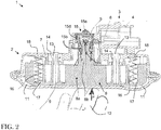
- the support on the control membrane 9 by the user 12 thus makes it possible to control the displacement of the actuating lever 8 over a predefined stroke C, for example of the order of 1.5 to 2 mm, between a position of rest ( figure 1 ) and a switching position ( figure 2 ).
- the tip 8c of the lever 8 presses the microswitch 5, causing the opening of the lock.
- the actuating lever 8 is in abutment on the base 7.
- the return means of the actuating lever 8 makes it possible to return the actuating lever 8 to the initial position of rest when the pressure ceases.
- the actuating lever 8 comprises for example assembly arms 13 cooperating with corresponding housings 14 of the base 7. There is for example an assembly arm 13 on either side of the central leg 8b of the lever. actuation 8.
- Each connecting arm 13 has an axis capable of sliding axially in an associated hole of the housing 14.
- the axis is terminated by a hook adapted to cooperate with a corresponding abutment around said orifice, at the end of the housing 14 of the base 7 in the rest position ( figure 1 ), so as to hold the lever 8 in the base 7 when it is biased by the biasing means.
- the assembly arms 13 In the switching position ( figure 2 ) in which the lever 8 has traveled the predefined stroke C, the assembly arms 13 have slid into the housing 14 until the pallet 8a abuts on the base 7.
- the electrical switch 1 further comprises a seal 15 between the microswitch 5 and the actuating lever 8, the seal 15 being configured to seal between the microswitch 5 and the actuating lever 8 in the two positions of the actuating lever 8.
- the seal 15 has for example an elastic peripheral end 15b cooperating with a complementary appendage carried by the tip 8c of the actuating lever 8 in the rest and switching positions of the actuating lever 8.
- the elastic properties of the seal 15 allow it to deform and retain the sealing properties in both positions of the actuating lever 8.
- the seal 15 peripheral to the area between the actuating lever 8 and the microswitch 5 then provides an electrical switch 1 waterproof, moisture or dust from outside the vehicle.
- the seal 15 is at least partially overmolded.
- the plastic used for overmolding is a "soft" plastic. It comprises for example a thermoplastic material, such as a TPE-S elastomer.
- the base 7, the actuating lever 8 and the electrical connector 4, for example are molded from a "hard” plastic, for example polypropylene.
- Elastomers have the advantage of strongly adhering to hard plastics, such as polypropylene, which consequently makes it possible to obtain a good seal.
- the pressures used in the injection machines are lower, which reduces the risk of deterioration of the switch during manufacture.
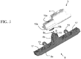
- the seal 15 is at least partially overmoulded on the microswitch 5 to form a cover 15a of the connection of the microswitch 5 where the electrical terminals 6 are connected. These are therefore protected.
- the seal 15 is completely made by a single overmolding step.
- the seal 15 comprising the lid 15a, the side chimneys 15d and the elastic peripheral end 15d is thus made in one piece, the injection of the overmolding taking place by the lid 15a, then by chimneys 15d side of both sides of the microswitch 5, to finish at the elastic peripheral end 15b.
- the electrical switch 1 can be arranged in any orientation, both vertically and horizontally.
- the base 7 is made of another hard plastic, such as polyamide 66 loaded with 30% glass fibers.
- the seal 15 does not overmold the base 7.
- the elastic peripheral end 15b has the shape of a tube ( figure 3A ) and the appendix has a complementary cylindrical shape inserted into an opening 15c of the tube.
- the elastic peripheral end 15b forms a bulge projecting at the opening 15c towards the complementary appendage of the tip 8c ( figure 3B ).
- the opening 15c of the tube has a diameter d of dimension smaller than the diameter D of the complementary appendix ( figure 5 ).
- the seal 15 is assembled on the actuating lever 8 by forcing a little during the introduction of the lever 8 into the seal 15.
- the end of the tube 15b is then compressed by this overlap, so that the area between the microswitch 5 and the tip of the lever 8c is made perfectly tight against water, moisture or dust.
- the elastic return means of the operating lever 8 in the rest position is formed by the compression of the seal 15.
- the force required to activate the electrical switch 1 is significantly reduced and has a reduced better reproducibility.
- the means of recall of the subset Mechanical 2 is thus provided by the seal 15. It can thus be dispensed with having springs between the base 7 and the actuating lever 8.
- a spring 16 may be placed on each side of the central leg 8b of the lever 8. For example, a first end of the spring 16 is received and fixed in a housing 17 of the pallet 8a of the actuating lever 8 and a second end of the spring 16 is fixed to a pin 18 of the base 7. It can thus be seen that the springs 16 are relaxed in the rest position ( figure 1 ) and compressed in the switching position ( figure 2 ).
- the complementary appendix of the tip 8c may comprise means for guiding and holding the peripheral end of the tube 15b.
- the guiding and holding means thus comprises an annular groove 19 receiving the peripheral end 15b.
- the annular groove 19 is formed inside by the side walls of the appendix of the nozzle 8c and outside by a cylindrical rim.
- the electric switch 1 thus obtained is therefore more robust, has a very high degree of tightness.
Claims (7)
- Elektrischer Schalter für eine Hecktür oder eine Heckklappe eines Kraftfahrzeugs, Folgendes umfassend:- einen Mikroschalter (5) und,- einen Betätigungshebel (8) für den besagten Mikroschalter (5), wobei der besagte Betätigungshebel (8) zwischen zwei Positionen, einer Ruheposition und einer Schaltposition, bewegt werden kann, in der er den besagten Mikroschalter (5) betätigt,dadurch gekennzeichnet, dass er darüber hinaus eine Dichtung (15) zwischen dem besagten Mikroschalter (5) und dem besagten Betätigungshebel (8) umfasst, wobei die besagte Dichtung (15) konfiguriert ist, um für die Abdichtung zwischen dem besagten Mikroschalter (5) und dem besagten Betätigungshebel (8) in den beiden Positionen des besagten Betätigungshebels (8) zu sorgen, dadurch gekennzeichnet, dass die
Dichtung (15) ein elastisches umlaufendes Ende (15b) aufweist, das mit einem ergänzenden Anhang des besagten Betätigungshebels (8) in den besagten Ruhe- und Schaltpositionen des besagten Betätigungshebels (8) zusammenwirkt,
und dadurch, dass die besagte Dichtung (15) einen Deckel (15a) des Anschlusses des Mikroschalters (5) und zumindest einen seitlichen Schacht (15d) umfasst, um den besagten Deckel (15a) mit dem besagten elastischen umlaufenden Ende (15b) zu verbinden, wobei die besagte Dichtung (15) in einem Stück durch Überformung ausgeführt ist. - Elektrischer Schalter nach Anspruch 1, dadurch gekennzeichnet, dass das besagte elastische umlaufende Ende (15b) die Form einer Röhre aufweist und dadurch, dass der besagte Anhang eine ergänzende zylindrische Form aufweist, die in eine Öffnung (15c) der besagten Röhre eingreift.
- Elektrischer Schalter nach Anspruch 2, dadurch gekennzeichnet, dass das besagte elastische umlaufende Ende (15b) eine Verdickung bildet, die im Bereich der besagten Öffnung (15c) der besagten Röhre zum besagten ergänzenden Anhang hin vorsteht.
- Elektrischer Schalter nach einem der Ansprüche 2 oder 3, dadurch gekennzeichnet, dass die besagte Öffnung (15c) der besagten Röhre einen Durchmesser (d) aufweist, dessen Abmessung kleiner ist, als der Durchmesser (D) des besagten ergänzenden Anhangs.
- Elektrischer Schalter nach einem der Ansprüche 1 bis 4, dadurch gekennzeichnet, dass der besagte ergänzende Anhang ein Mittel zum Führen und Festhalten des besagten umlaufenden Endes (15b) umfasst.
- Elektrischer Schalter nach Anspruch 5, gemeinsam mit einem der Ansprüche 2 bis 4, dadurch gekennzeichnet, dass das besagte Mittel zum Führen und Festhalten eine ringförmige Einkerbung (19) umfasst, die das besagte umlaufende Ende (15b) aufnimmt.
- Elektrischer Schalter nach Anspruch 1, dadurch gekennzeichnet, dass die besagte Dichtung (15) einen Thermoplast-Werkstoff wie ein TPE-S Elastomer umfasst.
Priority Applications (6)
| Application Number | Priority Date | Filing Date | Title |
|---|---|---|---|
| EP09382126.2A EP2282316B1 (de) | 2009-07-29 | 2009-07-29 | Elektrischer Umschalter für Tür oder Heckklappe eines Kraftfahrzeugs |
| IN1211DEN2012 IN2012DN01211A (de) | 2009-07-29 | 2010-07-23 | |
| JP2012522122A JP2013500561A (ja) | 2009-07-29 | 2010-07-23 | 車輌のリアドアまたはテールゲート用電気スイッチ |
| PCT/EP2010/060751 WO2011012556A1 (fr) | 2009-07-29 | 2010-07-23 | Commutateur électrique pour portière ou haillon arrière de véhicule automobile |
| BR112012000347-0A BR112012000347B1 (pt) | 2009-07-29 | 2010-07-23 | comutador elétrico para uma porta posterior ou porta traseira de um automóvel |
| KR1020127002241A KR101779219B1 (ko) | 2009-07-29 | 2010-07-23 | 자동차의 리어 도어 또는 테일게이트용 전기 스위치 |
Applications Claiming Priority (1)
| Application Number | Priority Date | Filing Date | Title |
|---|---|---|---|
| EP09382126.2A EP2282316B1 (de) | 2009-07-29 | 2009-07-29 | Elektrischer Umschalter für Tür oder Heckklappe eines Kraftfahrzeugs |
Publications (2)
| Publication Number | Publication Date |
|---|---|
| EP2282316A1 EP2282316A1 (de) | 2011-02-09 |
| EP2282316B1 true EP2282316B1 (de) | 2017-07-26 |
Family
ID=41404207
Family Applications (1)
| Application Number | Title | Priority Date | Filing Date |
|---|---|---|---|
| EP09382126.2A Active EP2282316B1 (de) | 2009-07-29 | 2009-07-29 | Elektrischer Umschalter für Tür oder Heckklappe eines Kraftfahrzeugs |
Country Status (6)
| Country | Link |
|---|---|
| EP (1) | EP2282316B1 (de) |
| JP (1) | JP2013500561A (de) |
| KR (1) | KR101779219B1 (de) |
| BR (1) | BR112012000347B1 (de) |
| IN (1) | IN2012DN01211A (de) |
| WO (1) | WO2011012556A1 (de) |
Families Citing this family (4)
| Publication number | Priority date | Publication date | Assignee | Title |
|---|---|---|---|---|
| DE102013218515A1 (de) * | 2013-09-16 | 2015-03-19 | Kiekert Ag | Elektrokomponententräger mit Mehrkomponentendeckel für Mikroschalter |
| EP2963667B1 (de) * | 2014-07-03 | 2017-05-17 | Valeo Equipements Electriques Moteur | Abdeckung eines Anlasserschalters für einen Kraftfahrzeug. |
| WO2017184107A1 (en) * | 2016-04-18 | 2017-10-26 | Gyrus Acmi Inc., D.B.A. Olympus Surgical Technologies America | Electronic switch mechanism |
| KR101927187B1 (ko) | 2017-02-27 | 2018-12-10 | 현대자동차 주식회사 | 차량용 트렁크 스위치 모듈 |
Citations (1)
| Publication number | Priority date | Publication date | Assignee | Title |
|---|---|---|---|---|
| WO2010072377A1 (de) * | 2008-12-22 | 2010-07-01 | Huf Hülsbeck & Fürst Gmbh & Co. Kg | Griff für türen oder klappen, insbesondere an fahrzeugen |
Family Cites Families (13)
| Publication number | Priority date | Publication date | Assignee | Title |
|---|---|---|---|---|
| JPS5952528U (ja) * | 1982-09-30 | 1984-04-06 | 長島 兼親 | 電気メス用耐熱、防水形ハンドスイツチ |
| DE3346296C2 (de) * | 1983-12-21 | 1994-05-19 | Siemens Ag | Betätigungselement zum Übertragen einer Linearbewegung an einen Schalter |
| JPS63285820A (ja) * | 1987-05-18 | 1988-11-22 | Omron Tateisi Electronics Co | 弾性シ−ル部材の被着方法 |
| DE9011110U1 (de) * | 1990-07-27 | 1990-10-04 | Dr. Eugen Sasse Gmbh, 8540 Schwabach, De | |
| IT236937Y1 (it) * | 1995-06-05 | 2000-08-31 | Bticino Spa | Pulsante luminoso in particolare per pulsantiere di impianticitofonici e videocitofonici |
| DE19856902C2 (de) * | 1998-12-10 | 2001-02-08 | Huf Huelsbeck & Fuerst Gmbh | Äußerer Türgriff, insbesondere für Fahrzeuge, mit einer Bügel-Handhabe und mit einem darin integrierten Druckbetätiger |
| JP2002014735A (ja) * | 2000-06-29 | 2002-01-18 | Nippon Seiki Co Ltd | スイッチ操作装置 |
| JP2002352662A (ja) * | 2001-03-16 | 2002-12-06 | Seiko Epson Corp | 押ボタン構造並びにこれを備えた電子機器及び時計 |
| US7772512B2 (en) * | 2004-04-07 | 2010-08-10 | T.K.M. Unlimited, Inc. | Push plate assembly |
| JP4644042B2 (ja) * | 2005-06-07 | 2011-03-02 | 三井金属アクト株式会社 | ラッチ解除操作装置 |
| US7250579B2 (en) * | 2005-09-21 | 2007-07-31 | Micro Pneumatic Logic, Inc. | Large actuation area switching device |
| JP4265680B2 (ja) * | 2006-12-01 | 2009-05-20 | カシオ計算機株式会社 | 電子機器 |
| JP4934074B2 (ja) * | 2007-03-07 | 2012-05-16 | 株式会社アルファ | スイッチ固定構造 |
-
2009
- 2009-07-29 EP EP09382126.2A patent/EP2282316B1/de active Active
-
2010
- 2010-07-23 KR KR1020127002241A patent/KR101779219B1/ko active IP Right Grant
- 2010-07-23 WO PCT/EP2010/060751 patent/WO2011012556A1/fr active Application Filing
- 2010-07-23 JP JP2012522122A patent/JP2013500561A/ja active Pending
- 2010-07-23 IN IN1211DEN2012 patent/IN2012DN01211A/en unknown
- 2010-07-23 BR BR112012000347-0A patent/BR112012000347B1/pt active IP Right Grant
Patent Citations (2)
| Publication number | Priority date | Publication date | Assignee | Title |
|---|---|---|---|---|
| WO2010072377A1 (de) * | 2008-12-22 | 2010-07-01 | Huf Hülsbeck & Fürst Gmbh & Co. Kg | Griff für türen oder klappen, insbesondere an fahrzeugen |
| EP2361338A1 (de) * | 2008-12-22 | 2011-08-31 | Huf Hülsbeck & Fürst GmbH & Co. KG | Griff für türen oder klappen, insbesondere an fahrzeugen |
Also Published As
| Publication number | Publication date |
|---|---|
| JP2013500561A (ja) | 2013-01-07 |
| IN2012DN01211A (de) | 2015-04-10 |
| WO2011012556A1 (fr) | 2011-02-03 |
| BR112012000347B1 (pt) | 2020-10-13 |
| KR101779219B1 (ko) | 2017-09-18 |
| EP2282316A1 (de) | 2011-02-09 |
| KR20120079460A (ko) | 2012-07-12 |
| BR112012000347A2 (pt) | 2016-03-22 |
Similar Documents
| Publication | Publication Date | Title |
|---|---|---|
| EP1026348B1 (de) | Sicherheitssystem für eine Kraftfahrzeugtür | |
| EP2282316B1 (de) | Elektrischer Umschalter für Tür oder Heckklappe eines Kraftfahrzeugs | |
| EP1442245A1 (de) | Einstückige schnappverbindung | |
| FR2915021A1 (fr) | Interrupteur electronique comportant une feuille elastique de positionnement horizontal du poussoir | |
| FR2904269A1 (fr) | Tubulure de remplissage du seservoir de carburant d'un vehicule automobile. | |
| FR3081264A1 (fr) | Dispositif de serrage de cable pour connecteur electrique etanche et connecteur electrique | |
| EP2811214A1 (de) | Schnelleinrastverbindung mit Riegeln mit symmetrischen Klemmbacken | |
| EP1383206A1 (de) | Koaxialverbindergehäuse und -element | |
| EP3599672A1 (de) | Anschluss mit hilfshebel zum anschliessen, und verpackungsverfahren eines solchen anschlusses | |
| FR2755790A1 (fr) | Commutateur a bouton-poussoir miniature, notamment pour une unite de disque souple | |
| EP2259279B1 (de) | Elektrischer Schalter und Herstellungsverfahren dieses Schalters für Hecktür oder Heckklappe eines Kraftfahrzeugs | |
| FR2899624A1 (fr) | Agencement d'un ouvrant sur un support | |
| EP1677324B1 (de) | Herstellungsverfahren eines Öffnungsschalters für Türen oder Kofferraum eines Kraftfahrzeuges und einen durch dieses Verfahren erhaltenen Schalter. | |
| FR2762807A1 (fr) | Embout de fermeture pour tubulure de remplissage d'un reservoir de carburant d'un vehicule automobile | |
| FR2893192A1 (fr) | Assemblage de connexion comportant une mecanisme de verrouillage et un element de blocage pour un tel assemblage de connexion | |
| FR2716581A1 (fr) | Joint de connecteur électrique. | |
| FR2712165A1 (fr) | Bonde à clapet pour appareil sanitaire du genre baignoire ou autre. | |
| FR2721791A1 (fr) | Boîtier muni d'un système d'encrantage libérable. | |
| FR2759871A1 (fr) | Etui pour telephone portable | |
| FR2842946A1 (fr) | Boitier pour piles ou accumulateurs | |
| WO2021240088A1 (fr) | Réservoir lave-glace de type souple doté d'un capotage rigide | |
| FR2478176A1 (fr) | Dispositif de blocage en position levee d'une piece mobile d'un vehicule automobile | |
| FR3024485A1 (fr) | Dispositif electronique de commande pour ouvrant de vehicule automobile et poignee d'ouvrant correspondante | |
| WO2023285474A1 (fr) | Boitier pour circuit imprime configure pour laisser emerger des fils electriques | |
| FR3105563A1 (fr) | Enjoliveur et commutateur électrique comprenant un tel enjoliveur |
Legal Events
| Date | Code | Title | Description |
|---|---|---|---|
| PUAI | Public reference made under article 153(3) epc to a published international application that has entered the european phase |
Free format text: ORIGINAL CODE: 0009012 |
|
| AK | Designated contracting states |
Kind code of ref document: A1 Designated state(s): AT BE BG CH CY CZ DE DK EE ES FI FR GB GR HR HU IE IS IT LI LT LU LV MC MK MT NL NO PL PT RO SE SI SK SM TR |
|
| AX | Request for extension of the european patent |
Extension state: AL BA RS |
|
| 17P | Request for examination filed |
Effective date: 20110728 |
|
| 17Q | First examination report despatched |
Effective date: 20110818 |
|
| RAP1 | Party data changed (applicant data changed or rights of an application transferred) |
Owner name: VALEO CLIMATIZACION S.A. |
|
| RAP1 | Party data changed (applicant data changed or rights of an application transferred) |
Owner name: U-SHIN SPAIN, SL |
|
| GRAP | Despatch of communication of intention to grant a patent |
Free format text: ORIGINAL CODE: EPIDOSNIGR1 |
|
| RIC1 | Information provided on ipc code assigned before grant |
Ipc: H01H 13/06 20060101AFI20151029BHEP Ipc: E05B 81/76 20140101ALI20151029BHEP |
|
| INTG | Intention to grant announced |
Effective date: 20151112 |
|
| 18D | Application deemed to be withdrawn |
Effective date: 20160323 |
|
| 18RA | Request filed for re-establishment of rights before grant |
Effective date: 20161024 |
|
| GRAS | Grant fee paid |
Free format text: ORIGINAL CODE: EPIDOSNIGR3 |
|
| D18D | Application deemed to be withdrawn (deleted) | ||
| GRAA | (expected) grant |
Free format text: ORIGINAL CODE: 0009210 |
|
| AK | Designated contracting states |
Kind code of ref document: B1 Designated state(s): AT BE BG CH CY CZ DE DK EE ES FI FR GB GR HR HU IE IS IT LI LT LU LV MC MK MT NL NO PL PT RO SE SI SK SM TR |
|
| REG | Reference to a national code |
Ref country code: CH Ref legal event code: EP |
|
| REG | Reference to a national code |
Ref country code: AT Ref legal event code: REF Ref document number: 913017 Country of ref document: AT Kind code of ref document: T Effective date: 20170815 |
|
| REG | Reference to a national code |
Ref country code: IE Ref legal event code: FG4D Free format text: LANGUAGE OF EP DOCUMENT: FRENCH |
|
| REG | Reference to a national code |
Ref country code: DE Ref legal event code: R096 Ref document number: 602009047327 Country of ref document: DE |
|
| REG | Reference to a national code |
Ref country code: FR Ref legal event code: PLFP Year of fee payment: 9 |
|
| REG | Reference to a national code |
Ref country code: NL Ref legal event code: MP Effective date: 20170726 |
|
| REG | Reference to a national code |
Ref country code: LT Ref legal event code: MG4D |
|
| REG | Reference to a national code |
Ref country code: AT Ref legal event code: MK05 Ref document number: 913017 Country of ref document: AT Kind code of ref document: T Effective date: 20170726 |
|
| PG25 | Lapsed in a contracting state [announced via postgrant information from national office to epo] |
Ref country code: SE Free format text: LAPSE BECAUSE OF FAILURE TO SUBMIT A TRANSLATION OF THE DESCRIPTION OR TO PAY THE FEE WITHIN THE PRESCRIBED TIME-LIMIT Effective date: 20170726 Ref country code: FI Free format text: LAPSE BECAUSE OF FAILURE TO SUBMIT A TRANSLATION OF THE DESCRIPTION OR TO PAY THE FEE WITHIN THE PRESCRIBED TIME-LIMIT Effective date: 20170726 Ref country code: NL Free format text: LAPSE BECAUSE OF FAILURE TO SUBMIT A TRANSLATION OF THE DESCRIPTION OR TO PAY THE FEE WITHIN THE PRESCRIBED TIME-LIMIT Effective date: 20170726 Ref country code: HR Free format text: LAPSE BECAUSE OF FAILURE TO SUBMIT A TRANSLATION OF THE DESCRIPTION OR TO PAY THE FEE WITHIN THE PRESCRIBED TIME-LIMIT Effective date: 20170726 Ref country code: LT Free format text: LAPSE BECAUSE OF FAILURE TO SUBMIT A TRANSLATION OF THE DESCRIPTION OR TO PAY THE FEE WITHIN THE PRESCRIBED TIME-LIMIT Effective date: 20170726 Ref country code: NO Free format text: LAPSE BECAUSE OF FAILURE TO SUBMIT A TRANSLATION OF THE DESCRIPTION OR TO PAY THE FEE WITHIN THE PRESCRIBED TIME-LIMIT Effective date: 20171026 Ref country code: AT Free format text: LAPSE BECAUSE OF FAILURE TO SUBMIT A TRANSLATION OF THE DESCRIPTION OR TO PAY THE FEE WITHIN THE PRESCRIBED TIME-LIMIT Effective date: 20170726 |
|
| PG25 | Lapsed in a contracting state [announced via postgrant information from national office to epo] |
Ref country code: IS Free format text: LAPSE BECAUSE OF FAILURE TO SUBMIT A TRANSLATION OF THE DESCRIPTION OR TO PAY THE FEE WITHIN THE PRESCRIBED TIME-LIMIT Effective date: 20171126 Ref country code: BG Free format text: LAPSE BECAUSE OF FAILURE TO SUBMIT A TRANSLATION OF THE DESCRIPTION OR TO PAY THE FEE WITHIN THE PRESCRIBED TIME-LIMIT Effective date: 20171026 Ref country code: PL Free format text: LAPSE BECAUSE OF FAILURE TO SUBMIT A TRANSLATION OF THE DESCRIPTION OR TO PAY THE FEE WITHIN THE PRESCRIBED TIME-LIMIT Effective date: 20170726 Ref country code: LV Free format text: LAPSE BECAUSE OF FAILURE TO SUBMIT A TRANSLATION OF THE DESCRIPTION OR TO PAY THE FEE WITHIN THE PRESCRIBED TIME-LIMIT Effective date: 20170726 Ref country code: GR Free format text: LAPSE BECAUSE OF FAILURE TO SUBMIT A TRANSLATION OF THE DESCRIPTION OR TO PAY THE FEE WITHIN THE PRESCRIBED TIME-LIMIT Effective date: 20171027 Ref country code: ES Free format text: LAPSE BECAUSE OF FAILURE TO SUBMIT A TRANSLATION OF THE DESCRIPTION OR TO PAY THE FEE WITHIN THE PRESCRIBED TIME-LIMIT Effective date: 20170726 |
|
| REG | Reference to a national code |
Ref country code: CH Ref legal event code: PL |
|
| PG25 | Lapsed in a contracting state [announced via postgrant information from national office to epo] |
Ref country code: CH Free format text: LAPSE BECAUSE OF NON-PAYMENT OF DUE FEES Effective date: 20170731 Ref country code: DK Free format text: LAPSE BECAUSE OF FAILURE TO SUBMIT A TRANSLATION OF THE DESCRIPTION OR TO PAY THE FEE WITHIN THE PRESCRIBED TIME-LIMIT Effective date: 20170726 Ref country code: MC Free format text: LAPSE BECAUSE OF FAILURE TO SUBMIT A TRANSLATION OF THE DESCRIPTION OR TO PAY THE FEE WITHIN THE PRESCRIBED TIME-LIMIT Effective date: 20170726 Ref country code: LI Free format text: LAPSE BECAUSE OF NON-PAYMENT OF DUE FEES Effective date: 20170731 Ref country code: CZ Free format text: LAPSE BECAUSE OF FAILURE TO SUBMIT A TRANSLATION OF THE DESCRIPTION OR TO PAY THE FEE WITHIN THE PRESCRIBED TIME-LIMIT Effective date: 20170726 |
|
| REG | Reference to a national code |
Ref country code: DE Ref legal event code: R097 Ref document number: 602009047327 Country of ref document: DE |
|
| REG | Reference to a national code |
Ref country code: IE Ref legal event code: MM4A |
|
| PG25 | Lapsed in a contracting state [announced via postgrant information from national office to epo] |
Ref country code: EE Free format text: LAPSE BECAUSE OF FAILURE TO SUBMIT A TRANSLATION OF THE DESCRIPTION OR TO PAY THE FEE WITHIN THE PRESCRIBED TIME-LIMIT Effective date: 20170726 Ref country code: IT Free format text: LAPSE BECAUSE OF FAILURE TO SUBMIT A TRANSLATION OF THE DESCRIPTION OR TO PAY THE FEE WITHIN THE PRESCRIBED TIME-LIMIT Effective date: 20170726 Ref country code: SK Free format text: LAPSE BECAUSE OF FAILURE TO SUBMIT A TRANSLATION OF THE DESCRIPTION OR TO PAY THE FEE WITHIN THE PRESCRIBED TIME-LIMIT Effective date: 20170726 Ref country code: SM Free format text: LAPSE BECAUSE OF FAILURE TO SUBMIT A TRANSLATION OF THE DESCRIPTION OR TO PAY THE FEE WITHIN THE PRESCRIBED TIME-LIMIT Effective date: 20170726 |
|
| PLBE | No opposition filed within time limit |
Free format text: ORIGINAL CODE: 0009261 |
|
| STAA | Information on the status of an ep patent application or granted ep patent |
Free format text: STATUS: NO OPPOSITION FILED WITHIN TIME LIMIT |
|
| REG | Reference to a national code |
Ref country code: BE Ref legal event code: MM Effective date: 20170731 |
|
| GBPC | Gb: european patent ceased through non-payment of renewal fee |
Effective date: 20171026 |
|
| PG25 | Lapsed in a contracting state [announced via postgrant information from national office to epo] |
Ref country code: LU Free format text: LAPSE BECAUSE OF NON-PAYMENT OF DUE FEES Effective date: 20170729 |
|
| 26N | No opposition filed |
Effective date: 20180430 |
|
| REG | Reference to a national code |
Ref country code: FR Ref legal event code: PLFP Year of fee payment: 10 |
|
| PG25 | Lapsed in a contracting state [announced via postgrant information from national office to epo] |
Ref country code: IE Free format text: LAPSE BECAUSE OF NON-PAYMENT OF DUE FEES Effective date: 20170729 Ref country code: GB Free format text: LAPSE BECAUSE OF NON-PAYMENT OF DUE FEES Effective date: 20171026 |
|
| PG25 | Lapsed in a contracting state [announced via postgrant information from national office to epo] |
Ref country code: SI Free format text: LAPSE BECAUSE OF FAILURE TO SUBMIT A TRANSLATION OF THE DESCRIPTION OR TO PAY THE FEE WITHIN THE PRESCRIBED TIME-LIMIT Effective date: 20170726 Ref country code: BE Free format text: LAPSE BECAUSE OF NON-PAYMENT OF DUE FEES Effective date: 20170731 |
|
| PG25 | Lapsed in a contracting state [announced via postgrant information from national office to epo] |
Ref country code: MT Free format text: LAPSE BECAUSE OF FAILURE TO SUBMIT A TRANSLATION OF THE DESCRIPTION OR TO PAY THE FEE WITHIN THE PRESCRIBED TIME-LIMIT Effective date: 20170726 |
|
| PG25 | Lapsed in a contracting state [announced via postgrant information from national office to epo] |
Ref country code: HU Free format text: LAPSE BECAUSE OF FAILURE TO SUBMIT A TRANSLATION OF THE DESCRIPTION OR TO PAY THE FEE WITHIN THE PRESCRIBED TIME-LIMIT; INVALID AB INITIO Effective date: 20090729 |
|
| PG25 | Lapsed in a contracting state [announced via postgrant information from national office to epo] |
Ref country code: RO Free format text: LAPSE BECAUSE OF FAILURE TO SUBMIT A TRANSLATION OF THE DESCRIPTION OR TO PAY THE FEE WITHIN THE PRESCRIBED TIME-LIMIT Effective date: 20170726 |
|
| PG25 | Lapsed in a contracting state [announced via postgrant information from national office to epo] |
Ref country code: CY Free format text: LAPSE BECAUSE OF NON-PAYMENT OF DUE FEES Effective date: 20170726 |
|
| PG25 | Lapsed in a contracting state [announced via postgrant information from national office to epo] |
Ref country code: MK Free format text: LAPSE BECAUSE OF FAILURE TO SUBMIT A TRANSLATION OF THE DESCRIPTION OR TO PAY THE FEE WITHIN THE PRESCRIBED TIME-LIMIT Effective date: 20170726 |
|
| PG25 | Lapsed in a contracting state [announced via postgrant information from national office to epo] |
Ref country code: TR Free format text: LAPSE BECAUSE OF FAILURE TO SUBMIT A TRANSLATION OF THE DESCRIPTION OR TO PAY THE FEE WITHIN THE PRESCRIBED TIME-LIMIT Effective date: 20170726 |
|
| PG25 | Lapsed in a contracting state [announced via postgrant information from national office to epo] |
Ref country code: PT Free format text: LAPSE BECAUSE OF FAILURE TO SUBMIT A TRANSLATION OF THE DESCRIPTION OR TO PAY THE FEE WITHIN THE PRESCRIBED TIME-LIMIT Effective date: 20170726 |
|
| PGFP | Annual fee paid to national office [announced via postgrant information from national office to epo] |
Ref country code: DE Payment date: 20220624 Year of fee payment: 14 |
|
| PGFP | Annual fee paid to national office [announced via postgrant information from national office to epo] |
Ref country code: FR Payment date: 20220726 Year of fee payment: 14 |
|
| REG | Reference to a national code |
Ref country code: DE Ref legal event code: R119 Ref document number: 602009047327 Country of ref document: DE |