EP2282316B1 - Electric switch for a rear door or tailgate of an automobile - Google Patents
Electric switch for a rear door or tailgate of an automobile Download PDFInfo
- Publication number
- EP2282316B1 EP2282316B1 EP09382126.2A EP09382126A EP2282316B1 EP 2282316 B1 EP2282316 B1 EP 2282316B1 EP 09382126 A EP09382126 A EP 09382126A EP 2282316 B1 EP2282316 B1 EP 2282316B1
- Authority
- EP
- European Patent Office
- Prior art keywords
- actuating lever
- peripheral end
- micro
- seal
- interrupter
- Prior art date
- Legal status (The legal status is an assumption and is not a legal conclusion. Google has not performed a legal analysis and makes no representation as to the accuracy of the status listed.)
- Active
Links
- 230000002093 peripheral effect Effects 0.000 claims description 21
- 230000000295 complement effect Effects 0.000 claims description 19
- 238000007789 sealing Methods 0.000 claims description 11
- 229920001971 elastomer Polymers 0.000 claims description 5
- 239000000806 elastomer Substances 0.000 claims description 5
- 239000012815 thermoplastic material Substances 0.000 claims description 3
- 230000037431 insertion Effects 0.000 claims 1
- 238000003780 insertion Methods 0.000 claims 1
- 239000012528 membrane Substances 0.000 description 9
- 239000004033 plastic Substances 0.000 description 7
- 229920003023 plastic Polymers 0.000 description 7
- 239000000428 dust Substances 0.000 description 5
- 238000006073 displacement reaction Methods 0.000 description 4
- 238000002347 injection Methods 0.000 description 4
- 239000007924 injection Substances 0.000 description 4
- XLYOFNOQVPJJNP-UHFFFAOYSA-N water Substances O XLYOFNOQVPJJNP-UHFFFAOYSA-N 0.000 description 4
- 239000004743 Polypropylene Substances 0.000 description 2
- 230000006835 compression Effects 0.000 description 2
- 238000007906 compression Methods 0.000 description 2
- 230000006866 deterioration Effects 0.000 description 2
- 238000004519 manufacturing process Methods 0.000 description 2
- -1 polypropylene Polymers 0.000 description 2
- 229920001155 polypropylene Polymers 0.000 description 2
- 229920002302 Nylon 6,6 Polymers 0.000 description 1
- 230000004913 activation Effects 0.000 description 1
- 230000008878 coupling Effects 0.000 description 1
- 238000010168 coupling process Methods 0.000 description 1
- 238000005859 coupling reaction Methods 0.000 description 1
- 239000003365 glass fiber Substances 0.000 description 1
- 239000002184 metal Substances 0.000 description 1
- 230000000284 resting effect Effects 0.000 description 1
- 238000003466 welding Methods 0.000 description 1
Images


Classifications
-
- H—ELECTRICITY
- H01—ELECTRIC ELEMENTS
- H01H—ELECTRIC SWITCHES; RELAYS; SELECTORS; EMERGENCY PROTECTIVE DEVICES
- H01H13/00—Switches having rectilinearly-movable operating part or parts adapted for pushing or pulling in one direction only, e.g. push-button switch
- H01H13/02—Details
- H01H13/04—Cases; Covers
- H01H13/06—Dustproof, splashproof, drip-proof, waterproof or flameproof casings
- H01H13/063—Casings hermetically closed by a diaphragm through which passes an actuating member
-
- E—FIXED CONSTRUCTIONS
- E05—LOCKS; KEYS; WINDOW OR DOOR FITTINGS; SAFES
- E05B—LOCKS; ACCESSORIES THEREFOR; HANDCUFFS
- E05B81/00—Power-actuated vehicle locks
- E05B81/54—Electrical circuits
- E05B81/64—Monitoring or sensing, e.g. by using switches or sensors
- E05B81/76—Detection of handle operation; Detection of a user approaching a handle; Electrical switching actions performed by door handles
-
- E—FIXED CONSTRUCTIONS
- E05—LOCKS; KEYS; WINDOW OR DOOR FITTINGS; SAFES
- E05B—LOCKS; ACCESSORIES THEREFOR; HANDCUFFS
- E05B83/00—Vehicle locks specially adapted for particular types of wing or vehicle
- E05B83/16—Locks for luggage compartments, car boot lids or car bonnets
- E05B83/18—Locks for luggage compartments, car boot lids or car bonnets for car boot lids or rear luggage compartments
-
- H—ELECTRICITY
- H01—ELECTRIC ELEMENTS
- H01H—ELECTRIC SWITCHES; RELAYS; SELECTORS; EMERGENCY PROTECTIVE DEVICES
- H01H3/00—Mechanisms for operating contacts
- H01H3/02—Operating parts, i.e. for operating driving mechanism by a mechanical force external to the switch
- H01H3/12—Push-buttons
- H01H3/122—Push-buttons with enlarged actuating area, e.g. of the elongated bar-type; Stabilising means therefor
-
- H—ELECTRICITY
- H01—ELECTRIC ELEMENTS
- H01H—ELECTRIC SWITCHES; RELAYS; SELECTORS; EMERGENCY PROTECTIVE DEVICES
- H01H2231/00—Applications
- H01H2231/026—Car
Definitions
- the present invention relates to an electric switch for opening a motor vehicle, such as a side door, a rear door trunk or rear hatch.
- the electrical switch opens the door, after unlocking the lock through the corresponding closure; manually or activated with the vehicle's remote control opening or vehicle owner's hands-free recognition system.
- Electric opening switches are known for a motor vehicle opening comprising a module closed by a membrane, the module being provided with mounting means on the frame of a side door or a rear door of the vehicle.
- the module comprises a mechanical subassembly comprising an actuating lever fixed under said membrane and an electrical subassembly comprising a microswitch connected to metal terminals.
- the lever is movable between two positions, a rest position and a switching position in which it engages said microswitch when the user presses on the membrane.
- the lever returns to its initial rest position by means of elastic return means when the pressure stops, the engagement of the microswitch causing the opening of the lock.
- the zone between the mechanical subassembly and the electrical subassembly may have an insufficient level of tightness, providing entry gates to moisture, water or dust from the outside of the vehicle and damage electrical circuits. The switches then lose their proper functioning.
- the document US 2005/224329 A1 discloses an electrical switch according to the preamble of claim 1.
- the present invention therefore aims to at least partially solve the problems of the state of the art by providing a robust electrical switch that has a better seal.
- the peripheral seal at the area between the operating lever and the microswitch then makes it possible to obtain an electrical switch that is impervious to water, humidity or dust from outside the vehicle. .
- the seal has an elastic peripheral end cooperating with a complementary appendix of said actuating lever in said resting and switching positions of said actuating lever.
- the elastic properties of the seal then allow it to deform and retain the sealing properties in both positions of the actuating lever.
- Said elastic peripheral end has for example the shape of a tube and said appendix has a complementary cylindrical shape inserted into an opening of said tube.
- Said elastic peripheral end has a bulge projecting at said opening of said tube to said complementary appendage.
- Said opening of said tube has for example a diameter smaller than the diameter of said complementary appendix.
- the seal is assembled on the actuating lever forcing a little during the introduction of the lever in the seal.
- the end of the tube is then slightly compressed by this overlap, so that the area between the microswitch and the lever is made perfectly tight against water, moisture or dust.
- the elastic return means of the actuating lever in the rest position is formed by the compression of the seal.
- the force required to activate the electrical switch is significantly reduced and has a better reproducibility.
- the means of recall of the subset mechanical is ensured by the seal. It is thus possible to dispense with having springs between the base and the actuating lever.
- Said complementary appendix may comprise means for guiding and holding said peripheral end.
- Said guiding and holding means may comprise an annular groove receiving said peripheral end.
- the outer wall of the end of the tube is held by the inner wall of the annular groove. In case of expansion of the tube, it is thus ensured that the diameter of the opening remains smaller than the external diameter of the complementary appendage so that the seal remains compressed against the complementary appendix and retains good sealing properties.
- said seal is at least partially overmolded.
- Said seal comprises for example a thermoplastic material, such as a TPE-S elastomer.
- Elastomers have the advantage of strongly adhering to hard plastics, which consequently makes it possible to obtain a good seal.
- the pressures used in the injection machines are lower, which reduces the risk of deterioration of the switch during manufacture.
- Said seal is overmolded on said microswitch to form a cover of the connector of said microswitch. These are then perfectly protected. Said seal comprises then a cover and at least one lateral chimney for connecting said cover to said elastic peripheral end, made in one piece by overmoulding in a single injection step.
- the electrical switch can be arranged in any orientation, both vertically and horizontally.
- the figure 1 represents an electrical switch 1 intended to be mounted on the frame of a motor vehicle door, such as a side door, a trunk door or rear hatch.
- the switch 1 can be disposed above the bumper in the case of a rear door electric door switch, for example in an upper part of an extension of the plastic part of the bumper.
- the electrical switch 1 causes the opening of the door, after unlocking the lock through the corresponding closure; Manually or remotely activated with the remote control of vehicle opening or hands-free recognition system of the vehicle owner.
- the electrical switch 1 comprises a mechanical subassembly 2 and an electrical subassembly 3.
- the electrical subassembly 3 comprises a connector 4 and a microswitch 5.
- the microswitch 5 is connected, for example by welding, to electrical terminals 6 ( figure 4 ).
- the microswitch 5 and the electrical terminals 6 are housed in the electrical connector 4.
- the connector 4 is intended to be connected to the electrical circuits arranged inside the vehicle.
- the electrical terminals 6 comprise, for example, connection pins at their ends.
- the connection pins then provide the function of a male connector capable of coupling to a suitable female connector.
- the mechanical subassembly 2 comprises a base 7, an actuating lever 8 of the microswitch 5, a flexible control membrane 9 and a return means of the actuating lever 8.
- the base 7 is closed by the flexible control membrane 9.
- the control membrane 9 is made accessible from the outside of the vehicle to activate the actuating lever 8.
- the mechanical and electrical subassemblies 2, 3 further include assembly means 10a, 10b, 10c cooperating to secure the subassemblies 2, 3 between them.
- the connector 4 has a slide 10a and lateral hooks 10b to cooperate with a complementary rib 10c carried by the base 7.
- the actuating lever 8 has the shape of a pallet 8a having a central leg 8b.
- the tip 8c of the central leg 8b is arranged axially at the microswitch 5.
- the control membrane 9 is fixed on a central portion of the pallet 8a, outside, leaving unfixed areas 11 at the periphery of the part to be able to be deformed during an order.
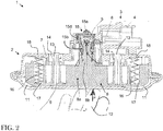
- the support on the control membrane 9 by the user 12 thus makes it possible to control the displacement of the actuating lever 8 over a predefined stroke C, for example of the order of 1.5 to 2 mm, between a position of rest ( figure 1 ) and a switching position ( figure 2 ).
- the tip 8c of the lever 8 presses the microswitch 5, causing the opening of the lock.
- the actuating lever 8 is in abutment on the base 7.
- the return means of the actuating lever 8 makes it possible to return the actuating lever 8 to the initial position of rest when the pressure ceases.
- the actuating lever 8 comprises for example assembly arms 13 cooperating with corresponding housings 14 of the base 7. There is for example an assembly arm 13 on either side of the central leg 8b of the lever. actuation 8.
- Each connecting arm 13 has an axis capable of sliding axially in an associated hole of the housing 14.
- the axis is terminated by a hook adapted to cooperate with a corresponding abutment around said orifice, at the end of the housing 14 of the base 7 in the rest position ( figure 1 ), so as to hold the lever 8 in the base 7 when it is biased by the biasing means.
- the assembly arms 13 In the switching position ( figure 2 ) in which the lever 8 has traveled the predefined stroke C, the assembly arms 13 have slid into the housing 14 until the pallet 8a abuts on the base 7.
- the electrical switch 1 further comprises a seal 15 between the microswitch 5 and the actuating lever 8, the seal 15 being configured to seal between the microswitch 5 and the actuating lever 8 in the two positions of the actuating lever 8.
- the seal 15 has for example an elastic peripheral end 15b cooperating with a complementary appendage carried by the tip 8c of the actuating lever 8 in the rest and switching positions of the actuating lever 8.
- the elastic properties of the seal 15 allow it to deform and retain the sealing properties in both positions of the actuating lever 8.
- the seal 15 peripheral to the area between the actuating lever 8 and the microswitch 5 then provides an electrical switch 1 waterproof, moisture or dust from outside the vehicle.
- the seal 15 is at least partially overmolded.
- the plastic used for overmolding is a "soft" plastic. It comprises for example a thermoplastic material, such as a TPE-S elastomer.
- the base 7, the actuating lever 8 and the electrical connector 4, for example are molded from a "hard” plastic, for example polypropylene.
- Elastomers have the advantage of strongly adhering to hard plastics, such as polypropylene, which consequently makes it possible to obtain a good seal.
- the pressures used in the injection machines are lower, which reduces the risk of deterioration of the switch during manufacture.
- the seal 15 is at least partially overmoulded on the microswitch 5 to form a cover 15a of the connection of the microswitch 5 where the electrical terminals 6 are connected. These are therefore protected.
- the seal 15 is completely made by a single overmolding step.
- the seal 15 comprising the lid 15a, the side chimneys 15d and the elastic peripheral end 15d is thus made in one piece, the injection of the overmolding taking place by the lid 15a, then by chimneys 15d side of both sides of the microswitch 5, to finish at the elastic peripheral end 15b.
- the electrical switch 1 can be arranged in any orientation, both vertically and horizontally.
- the base 7 is made of another hard plastic, such as polyamide 66 loaded with 30% glass fibers.
- the seal 15 does not overmold the base 7.
- the elastic peripheral end 15b has the shape of a tube ( figure 3A ) and the appendix has a complementary cylindrical shape inserted into an opening 15c of the tube.
- the elastic peripheral end 15b forms a bulge projecting at the opening 15c towards the complementary appendage of the tip 8c ( figure 3B ).
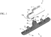
- the opening 15c of the tube has a diameter d of dimension smaller than the diameter D of the complementary appendix ( figure 5 ).
- the seal 15 is assembled on the actuating lever 8 by forcing a little during the introduction of the lever 8 into the seal 15.
- the end of the tube 15b is then compressed by this overlap, so that the area between the microswitch 5 and the tip of the lever 8c is made perfectly tight against water, moisture or dust.
- the elastic return means of the operating lever 8 in the rest position is formed by the compression of the seal 15.
- the force required to activate the electrical switch 1 is significantly reduced and has a reduced better reproducibility.
- the means of recall of the subset Mechanical 2 is thus provided by the seal 15. It can thus be dispensed with having springs between the base 7 and the actuating lever 8.
- a spring 16 may be placed on each side of the central leg 8b of the lever 8. For example, a first end of the spring 16 is received and fixed in a housing 17 of the pallet 8a of the actuating lever 8 and a second end of the spring 16 is fixed to a pin 18 of the base 7. It can thus be seen that the springs 16 are relaxed in the rest position ( figure 1 ) and compressed in the switching position ( figure 2 ).
- the complementary appendix of the tip 8c may comprise means for guiding and holding the peripheral end of the tube 15b.
- the guiding and holding means thus comprises an annular groove 19 receiving the peripheral end 15b.
- the annular groove 19 is formed inside by the side walls of the appendix of the nozzle 8c and outside by a cylindrical rim.
- the electric switch 1 thus obtained is therefore more robust, has a very high degree of tightness.
Description
La présente invention concerne un commutateur électrique pour ouvrant de véhicule automobile, tel qu'une portière latérale, une portière arrière de coffre ou le haillon arrière.The present invention relates to an electric switch for opening a motor vehicle, such as a side door, a rear door trunk or rear hatch.
Le commutateur électrique provoque l'ouverture de la porte, après avoir débloqué le verrou au travers de la fermeture correspondante ; manuellement ou activé avec la commande à distance d'ouverture du véhicule ou de système mains libres de reconnaissance du propriétaire du véhicule.The electrical switch opens the door, after unlocking the lock through the corresponding closure; manually or activated with the vehicle's remote control opening or vehicle owner's hands-free recognition system.
On connaît des commutateurs électriques d'ouverture pour ouvrant de véhicule automobile comportant un module fermé par une membrane, le module étant doté de moyens de montage sur le châssis d'une porte latérale ou d'une porte arrière de véhicule. Le module comporte un sous-ensemble mécanique comprenant un levier d'actionnement fixé sous ladite membrane et un sous-ensemble électrique comprenant un micro-interrupteur connecté à des terminaux métalliques.Electric opening switches are known for a motor vehicle opening comprising a module closed by a membrane, the module being provided with mounting means on the frame of a side door or a rear door of the vehicle. The module comprises a mechanical subassembly comprising an actuating lever fixed under said membrane and an electrical subassembly comprising a microswitch connected to metal terminals.
Le levier est déplaçable entre deux positions, une position de repos et une position de commutation dans laquelle il enclenche ledit micro-interrupteur lorsque l'usager appuie sur la membrane. Le levier revient à sa position initiale de repos grâce à des moyens de rappel élastique lorsque la pression cesse, l'enclenchement du micro-interrupteur provoquant l'ouverture de la serrure.The lever is movable between two positions, a rest position and a switching position in which it engages said microswitch when the user presses on the membrane. The lever returns to its initial rest position by means of elastic return means when the pressure stops, the engagement of the microswitch causing the opening of the lock.
Toutefois, la zone entre le sous-ensemble mécanique et le sous-ensemble électrique peut présenter un niveau d'étanchéité insuffisant, fournissant des portes d'entrée à l'humidité, l'eau ou la poussière en provenance de l'extérieur du véhicule et pouvant endommager les circuits électriques. Les commutateurs perdent alors leur bon fonctionnement.However, the zone between the mechanical subassembly and the electrical subassembly may have an insufficient level of tightness, providing entry gates to moisture, water or dust from the outside of the vehicle and damage electrical circuits. The switches then lose their proper functioning.
Le document
A cet effet, l'invention a pour objet un commutateur électrique selon la revendication 1 pour portière ou haillon arrière de véhicule automobile comprenant :
- un micro-interrupteur et,
- un levier d'actionnement dudit micro-interrupteur, ledit levier d'actionnement pouvant être déplacé entre deux positions, une position de repos et une position de commutation dans laquelle il actionne ledit micro-interrupteur,
- a micro-switch and,
- a lever for actuating said microswitch, said actuating lever being movable between two positions, a rest position and a switching position in which it actuates said microswitch,
Le joint d'étanchéité périphérique à la zone entre le levier d'actionnement et le micro-interrupteur permet alors d'obtenir un commutateur électrique étanche à l'eau, à l'humidité ou à la poussière en provenance de l'extérieur du véhicule.The peripheral seal at the area between the operating lever and the microswitch then makes it possible to obtain an electrical switch that is impervious to water, humidity or dust from outside the vehicle. .
Selon l'invention, le joint d'étanchéité présente une extrémité périphérique élastique coopérant avec un appendice complémentaire dudit levier d'actionnement dans lesdites positions de repos et de commutation dudit levier d'actionnement. Les propriétés élastiques du joint d'étanchéité lui permettent alors de se déformer et de conserver les propriétés d'étanchéité dans les deux positions du levier d'actionnement.According to the invention, the seal has an elastic peripheral end cooperating with a complementary appendix of said actuating lever in said resting and switching positions of said actuating lever. The elastic properties of the seal then allow it to deform and retain the sealing properties in both positions of the actuating lever.
Ladite extrémité périphérique élastique présente par exemple la forme d'un tube et ledit appendice présente une forme cylindrique complémentaire s'insérant dans une ouverture dudit tube.Said elastic peripheral end has for example the shape of a tube and said appendix has a complementary cylindrical shape inserted into an opening of said tube.
Ladite extrémité périphérique élastique présente un renflement faisant saillie au niveau de ladite ouverture dudit tube vers ledit appendice complémentaire. Ladite ouverture dudit tube présente par exemple un diamètre de dimension inférieure au diamètre dudit appendice complémentaire.Said elastic peripheral end has a bulge projecting at said opening of said tube to said complementary appendage. Said opening of said tube has for example a diameter smaller than the diameter of said complementary appendix.
Ainsi, le joint d'étanchéité est assemblé sur le levier d'actionnement en forçant un peu au cours de l'introduction du levier dans le joint. L'extrémité du tube est alors légèrement comprimée par ce chevauchement, de sorte que la zone entre le micro-interrupteur et le levier est rendue parfaitement étanche face à l'eau, l'humidité ou la poussière.Thus, the seal is assembled on the actuating lever forcing a little during the introduction of the lever in the seal. The end of the tube is then slightly compressed by this overlap, so that the area between the microswitch and the lever is made perfectly tight against water, moisture or dust.
En outre, le moyen de rappel élastique du levier d'actionnement dans la position de repos est formé par la compression du joint d'étanchéité. Ainsi, la force nécessaire pour activer le commutateur électrique est réduite de façon significative et présente une meilleure reproductibilité. Le moyen de rappel du sous-ensemble mécanique est ainsi assuré par le joint d'étanchéité. On peut ainsi s'affranchir de disposer des ressorts entre le socle et le levier d'actionnement.In addition, the elastic return means of the actuating lever in the rest position is formed by the compression of the seal. Thus, the force required to activate the electrical switch is significantly reduced and has a better reproducibility. The means of recall of the subset mechanical is ensured by the seal. It is thus possible to dispense with having springs between the base and the actuating lever.
Ledit appendice complémentaire peut comporter un moyen de guidage et de maintien de ladite extrémité périphérique. Ledit moyen de guidage et de maintien peut comporter une rainure annulaire recevant ladite extrémité périphérique.Said complementary appendix may comprise means for guiding and holding said peripheral end. Said guiding and holding means may comprise an annular groove receiving said peripheral end.
Une fois assemblés, la paroi externe de l'extrémité du tube est maintenue par la paroi interne de la rainure annulaire. En cas de dilatation du tube, on est ainsi assuré que le diamètre de l'ouverture reste de dimension inférieure au diamètre externe de l'appendice complémentaire de sorte que le joint d'étanchéité reste comprimé à l'encontre de l'appendice complémentaire et conserve de bonnes propriétés d'étanchéité.Once assembled, the outer wall of the end of the tube is held by the inner wall of the annular groove. In case of expansion of the tube, it is thus ensured that the diameter of the opening remains smaller than the external diameter of the complementary appendage so that the seal remains compressed against the complementary appendix and retains good sealing properties.
Selon l'invention, ledit joint d'étanchéité est au moins partiellement surmoulé.According to the invention, said seal is at least partially overmolded.
Ledit joint d'étanchéité comporte par exemple un matériau thermoplastique, tel qu'un élastomère TPE-S. Les élastomères présentent l'avantage de fortement adhérer sur les plastiques durs, ce qui permet par conséquent, d'obtenir un bon scellement. En outre, les pressions utilisées dans les machines d'injections sont plus faibles, ce qui réduit les risques de détérioration du commutateur au cours de la fabrication.Said seal comprises for example a thermoplastic material, such as a TPE-S elastomer. Elastomers have the advantage of strongly adhering to hard plastics, which consequently makes it possible to obtain a good seal. In addition, the pressures used in the injection machines are lower, which reduces the risk of deterioration of the switch during manufacture.
Ledit joint d'étanchéité est surmoulé sur ledit micro-interrupteur pour former un couvercle de la connectique dudit micro-interrupteur. Ceux-ci sont alors parfaitement protégés. Ledit joint d'étanchéité comporte alors un couvercle et au moins une cheminée latérale pour relier ledit couvercle à ladite extrémité périphérique élastique, réalisés en une seule pièce par surmoulage en une seule étape d'injection. En outre, étant donné que la connectique est complètement étanchéifiée, le commutateur électrique peut être disposé dans n'importe quelle orientation, aussi bien verticalement qu'horizontalement.Said seal is overmolded on said microswitch to form a cover of the connector of said microswitch. These are then perfectly protected. Said seal comprises then a cover and at least one lateral chimney for connecting said cover to said elastic peripheral end, made in one piece by overmoulding in a single injection step. In addition, since the connector is completely sealed, the electrical switch can be arranged in any orientation, both vertically and horizontally.
D'autres avantages et caractéristiques apparaîtront à la lecture de la description suivante d'un mode de réalisation particulier de l'invention, mais nullement limitatif, ainsi que des dessins annexés sur lesquels :
- la
figure 1 représente une vue en coupe d'un commutateur électrique en position de repos, - la
figure 2 représente une vue analogue à lafigure 1 dans laquelle le commutateur électrique est activé en position de commutation par un utilisateur, - la
figure 3A représente une vue en perspective et de dessous d'un sous-ensemble électrique, - la
figure 3B représente une vue en coupe du sous-ensemble électrique de lafigure 3A , - la
figure 4 est une vue schématique d'un micro-interrupteur connecté à des terminaux électriques, et - la
figure 5 est une vue en perspective du sous-ensemble électrique de lafigure 3A et d'un levier d'actionnement désassemblés.
- the
figure 1 represents a sectional view of an electrical switch in the rest position, - the
figure 2 represents a view similar to thefigure 1 in which the electrical switch is activated in the switching position by a user, - the
figure 3A represents a perspective view from below of an electrical subassembly, - the
figure 3B represents a sectional view of the electrical subassembly of thefigure 3A , - the
figure 4 is a schematic view of a micro-switch connected to electrical terminals, and - the
figure 5 is a perspective view of the electrical subassembly of thefigure 3A and a disassembled operating lever.
La
Le commutateur électrique 1 provoque l'ouverture de la porte, après avoir débloqué le verrou au travers de la fermeture correspondante ; manuellement ou à distance activé avec la commande à distance d'ouverture du véhicule ou de système mains libres de reconnaissance du propriétaire du véhicule.The
Le commutateur électrique 1 comprend un sous-ensemble mécanique 2 et un sous-ensemble électrique 3.The
Comme on peut mieux le voir sur l'exemple de la
Le micro-interrupteur 5 est connecté, par exemple par soudure, à des terminaux électriques 6 (
Les terminaux électriques 6 comportent par exemple des broches de connexion à leurs extrémités. Les broches de connexion assurent alors la fonction de connecteur mâle susceptible de s'accoupler sur un connecteur femelle approprié.The
Le sous-ensemble mécanique 2 comporte un socle 7, un levier d'actionnement 8 du micro-interrupteur 5, une membrane flexible de commande 9 et un moyen de rappel du levier d'actionnement 8.The
Le socle 7 est fermé par la membrane flexible de commande 9. La membrane de commande 9 est rendue accessible depuis l'extérieur du véhicule pour activer le levier d'actionnement 8.The
Les sous-ensembles mécanique et électrique 2, 3 comportent en outre des moyens d'assemblage 10a, 10b, 10c coopérant pour fixer les sous-ensembles 2, 3 entre eux.The mechanical and
Par exemple, et comme on peut le voir sur la
Comme visible sur l'exemple de la
Dans la position de repos (
Dans la position de commutation (
Selon le mode de réalisation représenté sur les
Chaque bras d'assemblage 13 présente un axe apte à coulisser axialement dans un orifice associé du logement 14. L'axe est terminé par un crochet apte à coopérer avec une butée correspondante autour dudit orifice, en bout du logement 14 du socle 7 dans la position de repos (
Le commutateur électrique 1 comporte en outre un joint d'étanchéité 15 entre le micro-interrupteur 5 et le levier d'actionnement 8, le joint d'étanchéité 15 étant configuré pour assurer l'étanchéité entre le micro-interrupteur 5 et le levier d'actionnement 8 dans les deux positions du levier d'actionnement 8.The
Le joint d'étanchéité 15 présente par exemple une extrémité périphérique élastique 15b coopérant avec un appendice complémentaire porté par l'embout 8c du levier d'actionnement 8 dans les positions de repos et de commutation du levier d'actionnement 8.The
Ainsi, lorsqu'un usager pousse sur le commutateur 1 (avec un effort par exemple compris entre 11 et 19 N, voir flèches F sur la
Les propriétés élastiques du joint d'étanchéité 15 lui permettent de se déformer et de conserver les propriétés d'étanchéité dans les deux positions du levier d'actionnement 8. Le joint d'étanchéité 15 périphérique à la zone entre le levier d'actionnement 8 et le micro-interrupteur 5 permet alors d'obtenir un commutateur électrique 1 étanche à l'eau, à l'humidité ou à la poussière en provenance de l'extérieur du véhicule.The elastic properties of the
Le joint d'étanchéité 15 est au moins partiellement surmoulé.The
Le plastique utilisé pour le surmoulage est un plastique « mou ». Il comporte par exemple un matériau thermoplastique, tel qu'un élastomère TPE-S. Le socle 7, le levier d'actionnement 8 et le connecteur électrique 4, sont par exemple moulés à partir d'un plastique « dur », par exemple du polypropylène.The plastic used for overmolding is a "soft" plastic. It comprises for example a thermoplastic material, such as a TPE-S elastomer. The
Les élastomères présentent l'avantage de fortement adhérer sur les plastiques durs, tels que le polypropylène, ce qui permet par conséquent, permet d'obtenir un bon scellement. En outre, les pressions utilisées pour dans les machines d'injections sont plus faibles, ce qui réduit les risques de détérioration du commutateur au cours de la fabrication.Elastomers have the advantage of strongly adhering to hard plastics, such as polypropylene, which consequently makes it possible to obtain a good seal. In addition, the pressures used in the injection machines are lower, which reduces the risk of deterioration of the switch during manufacture.
Par exemple, le joint d'étanchéité 15 est au moins partiellement surmoulé sur le micro-interrupteur 5 pour former un couvercle 15a de la connectique du micro-interrupteur 5 où les terminaux électriques 6 sont connectés. Ceux-ci sont donc protégés. De plus, le joint d'étanchéité 15 est totalement réalisé par une seule étape de surmoulage.For example, the
Le joint d'étanchéité 15 comportant le couvercle 15a, les cheminées latérales 15d et l'extrémité périphérique élastique 15d, est ainsi réalisé d'une seule pièce, l'injection du surmoulage ayant lieu par au niveau du couvercle 15a, puis par des cheminées latérales 15d de part et d'autre du micro-interrupteur 5, pour finir au niveau de l'extrémité périphérique élastique 15b.The
En outre, étant donné que la connectique est complètement étanchéifiée, le commutateur électrique 1 peut être disposé dans n'importe quelle orientation, aussi bien verticalement qu'horizontalement.In addition, since the connector is completely sealed, the
Alternativement, le socle 7 est réalisé par un autre plastique dur, tel que du polyamide 66 chargé en fibres de verre à 30%. Dans ce cas, le joint d'étanchéité 15 ne surmoule pas le socle 7.Alternatively, the
Selon le mode de réalisation représenté sur les figures et mieux visible sur le mode de réalisation de la
L'extrémité périphérique élastique 15b forme un renflement faisant saillie au niveau de l'ouverture 15c vers l'appendice complémentaire de l'embout 8c (
Ainsi, le joint d'étanchéité 15 est assemblé sur le levier d'actionnement 8 en forçant un peu au cours de l'introduction du levier 8 dans le joint 15. L'extrémité du tube 15b est alors comprimée par ce chevauchement, de sorte que la zone entre le micro-interrupteur 5 et l'embout du levier 8c est rendue parfaitement étanche face à l'eau, l'humidité ou la poussière.Thus, the
En outre, le moyen de rappel élastique du levier d'actionnement 8 dans la position de repos est formé par la compression du joint d'étanchéité 15. Ainsi, la force nécessaire pour activer le commutateur électrique 1 est réduite de façon significative et présente une meilleure reproductibilité. Le moyen de rappel du sous-ensemble mécanique 2 est ainsi assuré par le joint d'étanchéité 15. On peut ainsi s'affranchir de disposer des ressorts entre le socle 7 et le levier d'actionnement 8.In addition, the elastic return means of the operating
En complément du moyen de rappel formé par le joint d'étanchéité 15, on peut toutefois également disposer des ressorts. On peut disposer exemple un ressort 16 de chaque côté du pied central 8b du levier 8. Par exemple, une première terminaison du ressort 16 est reçue et fixée dans un logement 17 de la palette 8a du levier d'actionnement 8 et une deuxième terminaison du ressort 16 est fixée à un pion 18 du socle 7. On distingue ainsi que les ressorts 16 sont détendus dans la position de repos (
Par ailleurs, l'appendice complémentaire de l'embout 8c peut comporter un moyen de guidage et de maintien de l'extrémité périphérique du tube 15b.Furthermore, the complementary appendix of the
Selon l'exemple représenté sur la
Une fois le sous-ensemble électrique 3 assemblé au levier d'actionnement 8, la paroi externe de l'extrémité 15b est maintenue par la paroi interne de la bordure cylindrique de la rainure annulaire 19 (
Le commutateur électrique 1 ainsi obtenu est donc plus robuste, présente un très haut degré d'étanchéité.The
Claims (7)
- An electric switch for a door or tailgate of an automobile vehicle comprising:- un micro-interrupter (5) and,- an actuating lever (8) of said micro-interrupter (5), said actuating lever (8) being displaceable between two positions, a rest position and a switching position in which it actuates said micro-interrupter (5),characterized in that it further includes a sealing gasket (15) between said micro-interrupter (5) and said actuating lever (8), said sealing gasket (15) being configured to ensure sealing between said micro-interrupter (5) and said actuating lever (8) in the two positions of said actuating lever (8), characterized in that the sealing gasket (15) has an elastic peripheral end (15b) cooperating with a complementary appendix of said actuating lever (8) in said rest and switching positions of said actuating lever (8),
and in that said sealing gasket (15) includes a cover (15a) of the connections of the micro-interrupter (5) and at least one side chimney (15d) for linking said cover (15a) to said elastic peripheral end (15b), said sealing gasket (15) being made in one single part by overmolding. - The electric switch according to claim 1, characterized in that said elastic peripheral end (15b) has the shape of a tube and in that said appendix has a complementary cylindrical shape for insertion into an opening (15c) of said tube.
- The electric switch according to claim 2, characterized in that said elastic peripheral end (15b) forms a bulge projecting at said opening (15c) of said tube toward said complementary appendix.
- The electrical switch according to any of claims 2 or 3, characterized in that said opening (15c) of said tube has a diameter (d) of a dimension smaller than the diameter (D) of said complementary appendix.
- The electrical switch according to any of claims 1 to 4, characterized in that said complementary appendix includes a guiding and maintaining means of said peripheral end (15b).
- The electric switch according to claim 5, taken together with any of claims 2 to 4, characterized in that said guiding and maintaining means includes an annular groove (19) receiving said peripheral end (15b).
- The electric switch according to claim 1, characterized in that said sealing gasket (15) includes a thermoplastic material, such as TPE-S elastomer.
Priority Applications (6)
| Application Number | Priority Date | Filing Date | Title |
|---|---|---|---|
| EP09382126.2A EP2282316B1 (en) | 2009-07-29 | 2009-07-29 | Electric switch for a rear door or tailgate of an automobile |
| PCT/EP2010/060751 WO2011012556A1 (en) | 2009-07-29 | 2010-07-23 | Electric switch for a rear door or tailgate of an automobile |
| KR1020127002241A KR101779219B1 (en) | 2009-07-29 | 2010-07-23 | Electric switch for a rear door or tailgate of an automobile |
| BR112012000347-0A BR112012000347B1 (en) | 2009-07-29 | 2010-07-23 | electric switch for a rear or rear door of an automobile |
| JP2012522122A JP2013500561A (en) | 2009-07-29 | 2010-07-23 | Electrical switch for vehicle rear door or tailgate |
| IN1211DEN2012 IN2012DN01211A (en) | 2009-07-29 | 2010-07-23 |
Applications Claiming Priority (1)
| Application Number | Priority Date | Filing Date | Title |
|---|---|---|---|
| EP09382126.2A EP2282316B1 (en) | 2009-07-29 | 2009-07-29 | Electric switch for a rear door or tailgate of an automobile |
Publications (2)
| Publication Number | Publication Date |
|---|---|
| EP2282316A1 EP2282316A1 (en) | 2011-02-09 |
| EP2282316B1 true EP2282316B1 (en) | 2017-07-26 |
Family
ID=41404207
Family Applications (1)
| Application Number | Title | Priority Date | Filing Date |
|---|---|---|---|
| EP09382126.2A Active EP2282316B1 (en) | 2009-07-29 | 2009-07-29 | Electric switch for a rear door or tailgate of an automobile |
Country Status (6)
| Country | Link |
|---|---|
| EP (1) | EP2282316B1 (en) |
| JP (1) | JP2013500561A (en) |
| KR (1) | KR101779219B1 (en) |
| BR (1) | BR112012000347B1 (en) |
| IN (1) | IN2012DN01211A (en) |
| WO (1) | WO2011012556A1 (en) |
Families Citing this family (4)
| Publication number | Priority date | Publication date | Assignee | Title |
|---|---|---|---|---|
| DE102013218515A1 (en) * | 2013-09-16 | 2015-03-19 | Kiekert Ag | Electro component carrier with multi-component lid for microswitches |
| EP2963667B1 (en) * | 2014-07-03 | 2017-05-17 | Valeo Equipements Electriques Moteur | Cover of a contactor of starters for motor vehicle |
| WO2017184107A1 (en) * | 2016-04-18 | 2017-10-26 | Gyrus Acmi Inc., D.B.A. Olympus Surgical Technologies America | Electronic switch mechanism |
| KR101927187B1 (en) | 2017-02-27 | 2018-12-10 | 현대자동차 주식회사 | Trunk switch module for vehicle |
Citations (1)
| Publication number | Priority date | Publication date | Assignee | Title |
|---|---|---|---|---|
| WO2010072377A1 (en) * | 2008-12-22 | 2010-07-01 | Huf Hülsbeck & Fürst Gmbh & Co. Kg | Handle for doors or panels, especially on vehicles |
Family Cites Families (13)
| Publication number | Priority date | Publication date | Assignee | Title |
|---|---|---|---|---|
| JPS5952528U (en) * | 1982-09-30 | 1984-04-06 | 長島 兼親 | Heat-resistant, waterproof hand switch for electric scalpels |
| DE3346296C2 (en) * | 1983-12-21 | 1994-05-19 | Siemens Ag | Actuator for transmitting a linear movement to a switch |
| JPS63285820A (en) * | 1987-05-18 | 1988-11-22 | Omron Tateisi Electronics Co | Attaching method for flexible sealing member |
| DE9011110U1 (en) * | 1990-07-27 | 1990-10-04 | Dr. Eugen Sasse Gmbh, 8540 Schwabach, De | |
| IT236937Y1 (en) * | 1995-06-05 | 2000-08-31 | Bticino Spa | BRIGHT BUTTON IN PARTICULAR FOR ENTRANCE PANEL AND VIDEO DOOR ENTRY PANEL |
| DE19856902C2 (en) * | 1998-12-10 | 2001-02-08 | Huf Huelsbeck & Fuerst Gmbh | External door handle, especially for vehicles, with a handle and with a pressure actuator integrated into it |
| JP2002014735A (en) * | 2000-06-29 | 2002-01-18 | Nippon Seiki Co Ltd | Switch operation device |
| JP2002352662A (en) * | 2001-03-16 | 2002-12-06 | Seiko Epson Corp | Push-button structure and electronic equipment and timepiece provided with the same |
| US7772512B2 (en) * | 2004-04-07 | 2010-08-10 | T.K.M. Unlimited, Inc. | Push plate assembly |
| JP4644042B2 (en) * | 2005-06-07 | 2011-03-02 | 三井金属アクト株式会社 | Latch release operation device |
| US7250579B2 (en) * | 2005-09-21 | 2007-07-31 | Micro Pneumatic Logic, Inc. | Large actuation area switching device |
| JP4265680B2 (en) * | 2006-12-01 | 2009-05-20 | カシオ計算機株式会社 | Electronics |
| JP4934074B2 (en) * | 2007-03-07 | 2012-05-16 | 株式会社アルファ | Switch fixing structure |
-
2009
- 2009-07-29 EP EP09382126.2A patent/EP2282316B1/en active Active
-
2010
- 2010-07-23 IN IN1211DEN2012 patent/IN2012DN01211A/en unknown
- 2010-07-23 JP JP2012522122A patent/JP2013500561A/en active Pending
- 2010-07-23 KR KR1020127002241A patent/KR101779219B1/en active IP Right Grant
- 2010-07-23 WO PCT/EP2010/060751 patent/WO2011012556A1/en active Application Filing
- 2010-07-23 BR BR112012000347-0A patent/BR112012000347B1/en active IP Right Grant
Patent Citations (2)
| Publication number | Priority date | Publication date | Assignee | Title |
|---|---|---|---|---|
| WO2010072377A1 (en) * | 2008-12-22 | 2010-07-01 | Huf Hülsbeck & Fürst Gmbh & Co. Kg | Handle for doors or panels, especially on vehicles |
| EP2361338A1 (en) * | 2008-12-22 | 2011-08-31 | Huf Hülsbeck & Fürst GmbH & Co. KG | Handle for doors or panels, especially on vehicles |
Also Published As
| Publication number | Publication date |
|---|---|
| JP2013500561A (en) | 2013-01-07 |
| IN2012DN01211A (en) | 2015-04-10 |
| BR112012000347B1 (en) | 2020-10-13 |
| BR112012000347A2 (en) | 2016-03-22 |
| KR20120079460A (en) | 2012-07-12 |
| EP2282316A1 (en) | 2011-02-09 |
| WO2011012556A1 (en) | 2011-02-03 |
| KR101779219B1 (en) | 2017-09-18 |
Similar Documents
| Publication | Publication Date | Title |
|---|---|---|
| EP1026348B1 (en) | Security system for a motor vehicle door | |
| EP2282316B1 (en) | Electric switch for a rear door or tailgate of an automobile | |
| FR2915021A1 (en) | ELECTRONIC SWITCH COMPRISING AN ELASTIC SHEET HORIZONTALLY POSITIONING THE PUSHER | |
| WO2003025449A1 (en) | Single-piece snap-on connection | |
| FR2904269A1 (en) | Filler pipe for fuel tank of motor vehicle, has activating element cooperating with closure element that is movable between closing position and releasing position, where insert, closure element and activating element form monoblock part | |
| FR3081264A1 (en) | CABLE TIGHTENING DEVICE FOR SEALED ELECTRICAL CONNECTOR AND ELECTRICAL CONNECTOR | |
| EP2811214A1 (en) | Quick snap-on connector with locks having symmetrical jaws | |
| EP1383206A1 (en) | Coaxial connector casing and element | |
| EP3599672A1 (en) | Connector with lever for assisting with connection and method for packaging such a connector | |
| FR2755790A1 (en) | Helical coil contact mechanism for miniature push button switch | |
| EP2259279B1 (en) | Electric switch and method for manufacturing said switch for a rear door or tailgate of an automobile | |
| FR2899624A1 (en) | ARRANGEMENT OF AN OPENER ON A SUPPORT | |
| EP1677324B1 (en) | Manufactoring process of an opening switch for doors or trunk of vehicles, and switch produced by this process | |
| FR2762807A1 (en) | Closing end and cap for filling pipe of vehicle fuel tank | |
| FR2893192A1 (en) | Connecting arrangement e.g. electrical plug-in connecting arrangement, has securing unit with spring unit, which is pre-stressed in unlocking position for developing spring force and moves securing unit into locking position due to force | |
| FR2716581A1 (en) | Electrical connector seal. | |
| FR2712165A1 (en) | Plug for sanitary apparatus with mobile valve | |
| FR2721791A1 (en) | Electrical connection box with releasable catch | |
| FR2896876A1 (en) | DETECTION DEVICE AND SEAT COMPRISING SUCH A DEVICE | |
| FR2759871A1 (en) | CASE FOR MOBILE PHONE | |
| FR2842946A1 (en) | Box for batteries, comprises container with lid divided into two parts able to slide relatively under spring loading, a fixed part bearing contacts and a moving part including container catches | |
| WO2021240088A1 (en) | Flexible windscreen washer fluid tank equipped with a rigid cover | |
| FR2478176A1 (en) | Prop for car bonnet - has stop attached to one end by bayonet fixing engaging housing in bonnet | |
| FR3024485A1 (en) | ELECTRONIC CONTROL DEVICE FOR THE OPENING OF A MOTOR VEHICLE AND CORRESPONDING OPENING HANDLE | |
| WO2023285474A1 (en) | Printed circuit housing configured to allow the electrical wires to emerge |
Legal Events
| Date | Code | Title | Description |
|---|---|---|---|
| PUAI | Public reference made under article 153(3) epc to a published international application that has entered the european phase |
Free format text: ORIGINAL CODE: 0009012 |
|
| AK | Designated contracting states |
Kind code of ref document: A1 Designated state(s): AT BE BG CH CY CZ DE DK EE ES FI FR GB GR HR HU IE IS IT LI LT LU LV MC MK MT NL NO PL PT RO SE SI SK SM TR |
|
| AX | Request for extension of the european patent |
Extension state: AL BA RS |
|
| 17P | Request for examination filed |
Effective date: 20110728 |
|
| 17Q | First examination report despatched |
Effective date: 20110818 |
|
| RAP1 | Party data changed (applicant data changed or rights of an application transferred) |
Owner name: VALEO CLIMATIZACION S.A. |
|
| RAP1 | Party data changed (applicant data changed or rights of an application transferred) |
Owner name: U-SHIN SPAIN, SL |
|
| GRAP | Despatch of communication of intention to grant a patent |
Free format text: ORIGINAL CODE: EPIDOSNIGR1 |
|
| RIC1 | Information provided on ipc code assigned before grant |
Ipc: H01H 13/06 20060101AFI20151029BHEP Ipc: E05B 81/76 20140101ALI20151029BHEP |
|
| INTG | Intention to grant announced |
Effective date: 20151112 |
|
| 18D | Application deemed to be withdrawn |
Effective date: 20160323 |
|
| 18RA | Request filed for re-establishment of rights before grant |
Effective date: 20161024 |
|
| GRAS | Grant fee paid |
Free format text: ORIGINAL CODE: EPIDOSNIGR3 |
|
| D18D | Application deemed to be withdrawn (deleted) | ||
| GRAA | (expected) grant |
Free format text: ORIGINAL CODE: 0009210 |
|
| AK | Designated contracting states |
Kind code of ref document: B1 Designated state(s): AT BE BG CH CY CZ DE DK EE ES FI FR GB GR HR HU IE IS IT LI LT LU LV MC MK MT NL NO PL PT RO SE SI SK SM TR |
|
| REG | Reference to a national code |
Ref country code: CH Ref legal event code: EP |
|
| REG | Reference to a national code |
Ref country code: AT Ref legal event code: REF Ref document number: 913017 Country of ref document: AT Kind code of ref document: T Effective date: 20170815 |
|
| REG | Reference to a national code |
Ref country code: IE Ref legal event code: FG4D Free format text: LANGUAGE OF EP DOCUMENT: FRENCH |
|
| REG | Reference to a national code |
Ref country code: DE Ref legal event code: R096 Ref document number: 602009047327 Country of ref document: DE |
|
| REG | Reference to a national code |
Ref country code: FR Ref legal event code: PLFP Year of fee payment: 9 |
|
| REG | Reference to a national code |
Ref country code: NL Ref legal event code: MP Effective date: 20170726 |
|
| REG | Reference to a national code |
Ref country code: LT Ref legal event code: MG4D |
|
| REG | Reference to a national code |
Ref country code: AT Ref legal event code: MK05 Ref document number: 913017 Country of ref document: AT Kind code of ref document: T Effective date: 20170726 |
|
| PG25 | Lapsed in a contracting state [announced via postgrant information from national office to epo] |
Ref country code: SE Free format text: LAPSE BECAUSE OF FAILURE TO SUBMIT A TRANSLATION OF THE DESCRIPTION OR TO PAY THE FEE WITHIN THE PRESCRIBED TIME-LIMIT Effective date: 20170726 Ref country code: FI Free format text: LAPSE BECAUSE OF FAILURE TO SUBMIT A TRANSLATION OF THE DESCRIPTION OR TO PAY THE FEE WITHIN THE PRESCRIBED TIME-LIMIT Effective date: 20170726 Ref country code: NL Free format text: LAPSE BECAUSE OF FAILURE TO SUBMIT A TRANSLATION OF THE DESCRIPTION OR TO PAY THE FEE WITHIN THE PRESCRIBED TIME-LIMIT Effective date: 20170726 Ref country code: HR Free format text: LAPSE BECAUSE OF FAILURE TO SUBMIT A TRANSLATION OF THE DESCRIPTION OR TO PAY THE FEE WITHIN THE PRESCRIBED TIME-LIMIT Effective date: 20170726 Ref country code: LT Free format text: LAPSE BECAUSE OF FAILURE TO SUBMIT A TRANSLATION OF THE DESCRIPTION OR TO PAY THE FEE WITHIN THE PRESCRIBED TIME-LIMIT Effective date: 20170726 Ref country code: NO Free format text: LAPSE BECAUSE OF FAILURE TO SUBMIT A TRANSLATION OF THE DESCRIPTION OR TO PAY THE FEE WITHIN THE PRESCRIBED TIME-LIMIT Effective date: 20171026 Ref country code: AT Free format text: LAPSE BECAUSE OF FAILURE TO SUBMIT A TRANSLATION OF THE DESCRIPTION OR TO PAY THE FEE WITHIN THE PRESCRIBED TIME-LIMIT Effective date: 20170726 |
|
| PG25 | Lapsed in a contracting state [announced via postgrant information from national office to epo] |
Ref country code: IS Free format text: LAPSE BECAUSE OF FAILURE TO SUBMIT A TRANSLATION OF THE DESCRIPTION OR TO PAY THE FEE WITHIN THE PRESCRIBED TIME-LIMIT Effective date: 20171126 Ref country code: BG Free format text: LAPSE BECAUSE OF FAILURE TO SUBMIT A TRANSLATION OF THE DESCRIPTION OR TO PAY THE FEE WITHIN THE PRESCRIBED TIME-LIMIT Effective date: 20171026 Ref country code: PL Free format text: LAPSE BECAUSE OF FAILURE TO SUBMIT A TRANSLATION OF THE DESCRIPTION OR TO PAY THE FEE WITHIN THE PRESCRIBED TIME-LIMIT Effective date: 20170726 Ref country code: LV Free format text: LAPSE BECAUSE OF FAILURE TO SUBMIT A TRANSLATION OF THE DESCRIPTION OR TO PAY THE FEE WITHIN THE PRESCRIBED TIME-LIMIT Effective date: 20170726 Ref country code: GR Free format text: LAPSE BECAUSE OF FAILURE TO SUBMIT A TRANSLATION OF THE DESCRIPTION OR TO PAY THE FEE WITHIN THE PRESCRIBED TIME-LIMIT Effective date: 20171027 Ref country code: ES Free format text: LAPSE BECAUSE OF FAILURE TO SUBMIT A TRANSLATION OF THE DESCRIPTION OR TO PAY THE FEE WITHIN THE PRESCRIBED TIME-LIMIT Effective date: 20170726 |
|
| REG | Reference to a national code |
Ref country code: CH Ref legal event code: PL |
|
| PG25 | Lapsed in a contracting state [announced via postgrant information from national office to epo] |
Ref country code: CH Free format text: LAPSE BECAUSE OF NON-PAYMENT OF DUE FEES Effective date: 20170731 Ref country code: DK Free format text: LAPSE BECAUSE OF FAILURE TO SUBMIT A TRANSLATION OF THE DESCRIPTION OR TO PAY THE FEE WITHIN THE PRESCRIBED TIME-LIMIT Effective date: 20170726 Ref country code: MC Free format text: LAPSE BECAUSE OF FAILURE TO SUBMIT A TRANSLATION OF THE DESCRIPTION OR TO PAY THE FEE WITHIN THE PRESCRIBED TIME-LIMIT Effective date: 20170726 Ref country code: LI Free format text: LAPSE BECAUSE OF NON-PAYMENT OF DUE FEES Effective date: 20170731 Ref country code: CZ Free format text: LAPSE BECAUSE OF FAILURE TO SUBMIT A TRANSLATION OF THE DESCRIPTION OR TO PAY THE FEE WITHIN THE PRESCRIBED TIME-LIMIT Effective date: 20170726 |
|
| REG | Reference to a national code |
Ref country code: DE Ref legal event code: R097 Ref document number: 602009047327 Country of ref document: DE |
|
| REG | Reference to a national code |
Ref country code: IE Ref legal event code: MM4A |
|
| PG25 | Lapsed in a contracting state [announced via postgrant information from national office to epo] |
Ref country code: EE Free format text: LAPSE BECAUSE OF FAILURE TO SUBMIT A TRANSLATION OF THE DESCRIPTION OR TO PAY THE FEE WITHIN THE PRESCRIBED TIME-LIMIT Effective date: 20170726 Ref country code: IT Free format text: LAPSE BECAUSE OF FAILURE TO SUBMIT A TRANSLATION OF THE DESCRIPTION OR TO PAY THE FEE WITHIN THE PRESCRIBED TIME-LIMIT Effective date: 20170726 Ref country code: SK Free format text: LAPSE BECAUSE OF FAILURE TO SUBMIT A TRANSLATION OF THE DESCRIPTION OR TO PAY THE FEE WITHIN THE PRESCRIBED TIME-LIMIT Effective date: 20170726 Ref country code: SM Free format text: LAPSE BECAUSE OF FAILURE TO SUBMIT A TRANSLATION OF THE DESCRIPTION OR TO PAY THE FEE WITHIN THE PRESCRIBED TIME-LIMIT Effective date: 20170726 |
|
| PLBE | No opposition filed within time limit |
Free format text: ORIGINAL CODE: 0009261 |
|
| STAA | Information on the status of an ep patent application or granted ep patent |
Free format text: STATUS: NO OPPOSITION FILED WITHIN TIME LIMIT |
|
| REG | Reference to a national code |
Ref country code: BE Ref legal event code: MM Effective date: 20170731 |
|
| GBPC | Gb: european patent ceased through non-payment of renewal fee |
Effective date: 20171026 |
|
| PG25 | Lapsed in a contracting state [announced via postgrant information from national office to epo] |
Ref country code: LU Free format text: LAPSE BECAUSE OF NON-PAYMENT OF DUE FEES Effective date: 20170729 |
|
| 26N | No opposition filed |
Effective date: 20180430 |
|
| REG | Reference to a national code |
Ref country code: FR Ref legal event code: PLFP Year of fee payment: 10 |
|
| PG25 | Lapsed in a contracting state [announced via postgrant information from national office to epo] |
Ref country code: IE Free format text: LAPSE BECAUSE OF NON-PAYMENT OF DUE FEES Effective date: 20170729 Ref country code: GB Free format text: LAPSE BECAUSE OF NON-PAYMENT OF DUE FEES Effective date: 20171026 |
|
| PG25 | Lapsed in a contracting state [announced via postgrant information from national office to epo] |
Ref country code: SI Free format text: LAPSE BECAUSE OF FAILURE TO SUBMIT A TRANSLATION OF THE DESCRIPTION OR TO PAY THE FEE WITHIN THE PRESCRIBED TIME-LIMIT Effective date: 20170726 Ref country code: BE Free format text: LAPSE BECAUSE OF NON-PAYMENT OF DUE FEES Effective date: 20170731 |
|
| PG25 | Lapsed in a contracting state [announced via postgrant information from national office to epo] |
Ref country code: MT Free format text: LAPSE BECAUSE OF FAILURE TO SUBMIT A TRANSLATION OF THE DESCRIPTION OR TO PAY THE FEE WITHIN THE PRESCRIBED TIME-LIMIT Effective date: 20170726 |
|
| PG25 | Lapsed in a contracting state [announced via postgrant information from national office to epo] |
Ref country code: HU Free format text: LAPSE BECAUSE OF FAILURE TO SUBMIT A TRANSLATION OF THE DESCRIPTION OR TO PAY THE FEE WITHIN THE PRESCRIBED TIME-LIMIT; INVALID AB INITIO Effective date: 20090729 |
|
| PG25 | Lapsed in a contracting state [announced via postgrant information from national office to epo] |
Ref country code: RO Free format text: LAPSE BECAUSE OF FAILURE TO SUBMIT A TRANSLATION OF THE DESCRIPTION OR TO PAY THE FEE WITHIN THE PRESCRIBED TIME-LIMIT Effective date: 20170726 |
|
| PG25 | Lapsed in a contracting state [announced via postgrant information from national office to epo] |
Ref country code: CY Free format text: LAPSE BECAUSE OF NON-PAYMENT OF DUE FEES Effective date: 20170726 |
|
| PG25 | Lapsed in a contracting state [announced via postgrant information from national office to epo] |
Ref country code: MK Free format text: LAPSE BECAUSE OF FAILURE TO SUBMIT A TRANSLATION OF THE DESCRIPTION OR TO PAY THE FEE WITHIN THE PRESCRIBED TIME-LIMIT Effective date: 20170726 |
|
| PG25 | Lapsed in a contracting state [announced via postgrant information from national office to epo] |
Ref country code: TR Free format text: LAPSE BECAUSE OF FAILURE TO SUBMIT A TRANSLATION OF THE DESCRIPTION OR TO PAY THE FEE WITHIN THE PRESCRIBED TIME-LIMIT Effective date: 20170726 |
|
| PG25 | Lapsed in a contracting state [announced via postgrant information from national office to epo] |
Ref country code: PT Free format text: LAPSE BECAUSE OF FAILURE TO SUBMIT A TRANSLATION OF THE DESCRIPTION OR TO PAY THE FEE WITHIN THE PRESCRIBED TIME-LIMIT Effective date: 20170726 |
|
| PGFP | Annual fee paid to national office [announced via postgrant information from national office to epo] |
Ref country code: DE Payment date: 20220624 Year of fee payment: 14 |
|
| PGFP | Annual fee paid to national office [announced via postgrant information from national office to epo] |
Ref country code: FR Payment date: 20220726 Year of fee payment: 14 |
|
| REG | Reference to a national code |
Ref country code: DE Ref legal event code: R119 Ref document number: 602009047327 Country of ref document: DE |