EP2281992A2 - Ganzglasflügel und Verfahren zur Montage eines Ganzglasflügels - Google Patents
Ganzglasflügel und Verfahren zur Montage eines Ganzglasflügels Download PDFInfo
- Publication number
- EP2281992A2 EP2281992A2 EP10167284A EP10167284A EP2281992A2 EP 2281992 A2 EP2281992 A2 EP 2281992A2 EP 10167284 A EP10167284 A EP 10167284A EP 10167284 A EP10167284 A EP 10167284A EP 2281992 A2 EP2281992 A2 EP 2281992A2
- Authority
- EP
- European Patent Office
- Prior art keywords
- profile
- disc
- edge profile
- contact surface
- edge
- Prior art date
- Legal status (The legal status is an assumption and is not a legal conclusion. Google has not performed a legal analysis and makes no representation as to the accuracy of the status listed.)
- Withdrawn
Links
- 238000000034 method Methods 0.000 title claims abstract description 4
- 239000011521 glass Substances 0.000 title abstract description 11
- 239000000853 adhesive Substances 0.000 claims description 11
- 230000001070 adhesive effect Effects 0.000 claims description 11
- 239000005340 laminated glass Substances 0.000 claims description 5
- 230000000295 complement effect Effects 0.000 claims description 4
- 230000005855 radiation Effects 0.000 claims description 3
- 239000002131 composite material Substances 0.000 abstract 1
- 238000005192 partition Methods 0.000 description 7
- 239000010410 layer Substances 0.000 description 6
- 238000009434 installation Methods 0.000 description 3
- 238000001723 curing Methods 0.000 description 2
- 239000000499 gel Substances 0.000 description 2
- 239000000725 suspension Substances 0.000 description 2
- 238000004026 adhesive bonding Methods 0.000 description 1
- 239000011248 coating agent Substances 0.000 description 1
- 238000000576 coating method Methods 0.000 description 1
- 230000002349 favourable effect Effects 0.000 description 1
- 239000011229 interlayer Substances 0.000 description 1
- 230000014759 maintenance of location Effects 0.000 description 1
- 239000000463 material Substances 0.000 description 1
- 238000003847 radiation curing Methods 0.000 description 1
- 230000000284 resting effect Effects 0.000 description 1
- 238000011179 visual inspection Methods 0.000 description 1
Images


Classifications
-
- E—FIXED CONSTRUCTIONS
- E06—DOORS, WINDOWS, SHUTTERS, OR ROLLER BLINDS IN GENERAL; LADDERS
- E06B—FIXED OR MOVABLE CLOSURES FOR OPENINGS IN BUILDINGS, VEHICLES, FENCES OR LIKE ENCLOSURES IN GENERAL, e.g. DOORS, WINDOWS, BLINDS, GATES
- E06B3/00—Window sashes, door leaves, or like elements for closing wall or like openings; Layout of fixed or moving closures, e.g. windows in wall or like openings; Features of rigidly-mounted outer frames relating to the mounting of wing frames
- E06B3/02—Wings made completely of glass
-
- E—FIXED CONSTRUCTIONS
- E06—DOORS, WINDOWS, SHUTTERS, OR ROLLER BLINDS IN GENERAL; LADDERS
- E06B—FIXED OR MOVABLE CLOSURES FOR OPENINGS IN BUILDINGS, VEHICLES, FENCES OR LIKE ENCLOSURES IN GENERAL, e.g. DOORS, WINDOWS, BLINDS, GATES
- E06B3/00—Window sashes, door leaves, or like elements for closing wall or like openings; Layout of fixed or moving closures, e.g. windows in wall or like openings; Features of rigidly-mounted outer frames relating to the mounting of wing frames
- E06B3/32—Arrangements of wings characterised by the manner of movement; Arrangements of movable wings in openings; Features of wings or frames relating solely to the manner of movement of the wing
- E06B3/34—Arrangements of wings characterised by the manner of movement; Arrangements of movable wings in openings; Features of wings or frames relating solely to the manner of movement of the wing with only one kind of movement
- E06B3/42—Sliding wings; Details of frames with respect to guiding
- E06B3/46—Horizontally-sliding wings
- E06B3/4681—Horizontally-sliding wings made of glass panes without frames
-
- E—FIXED CONSTRUCTIONS
- E06—DOORS, WINDOWS, SHUTTERS, OR ROLLER BLINDS IN GENERAL; LADDERS
- E06B—FIXED OR MOVABLE CLOSURES FOR OPENINGS IN BUILDINGS, VEHICLES, FENCES OR LIKE ENCLOSURES IN GENERAL, e.g. DOORS, WINDOWS, BLINDS, GATES
- E06B3/00—Window sashes, door leaves, or like elements for closing wall or like openings; Layout of fixed or moving closures, e.g. windows in wall or like openings; Features of rigidly-mounted outer frames relating to the mounting of wing frames
- E06B3/54—Fixing of glass panes or like plates
- E06B3/549—Fixing of glass panes or like plates by clamping the pane between two subframes
Definitions
- the invention relates to a wing of a door or a window with at least one glass pane according to the preamble of patent claim 1 and a method for assembling a wing according to the preamble of claim 11.
- An edge profile serves for the hanging arrangement of the glass pane.
- the edge profile is arranged in the upper region of the disc and has two side webs which at least partially cover the upper edge region of the disc and cooperate with the side surfaces of the disc by a respective retaining profile is glued on each side surface of the disc in the region of its horizontal upper edge and the Holding profiles rest on inwardly directed projections of the side webs.
- the invention has for its object to provide a wing that has a simplified installation and also allows the use of existing edge profiles in conjunction with a laminated glass.
- the retaining profile is fixed only on one side surface of the disc, while between the other side surface of the disc and the corresponding side bar of the edge profile, a separately insertable securing profile is arranged.
- the assembly of the wing is considerably simplified, since the disc with the retaining profile glued on one side does not have to be pushed into the edge profile on the face side.
- the provided with the retaining profile upper edge of the disc can be brought from the respective handling moderately favorable side, in particular from below between the side webs of the edge profile, whereupon the separate securing profile on the side facing away from the holding profile of the disc between the side web of the edge profile and the disc are inserted can and finally then the side bars of the edge profile in their final mounting position moves towards each other and fixed there.
- the side webs of the edge profile each have a contact surface which cooperates with the retaining profile or the securing profile.
- the contact surface of the edge profile may at least partially have a sawtooth-like surface, whereby a secure hold of the disc is achieved in the edge profile.
- the contact surface of the edge profile, also to achieve a secure hold of the disc in the edge profile have at least one projection.
- the retaining profile has a contact surface which cooperates with the contact surface of the edge profile.
- the contact surface of the holding profile may at least in sections have a complementary to the contact surface of the edge profile surface, for example, sawtooth-shaped.
- the contact surfaces of the edge profile and / or the holding profile may have a high coefficient of friction, for example by an appropriate selection of materials, surface design and / or coating.
- the holding profile can be fixed to the pane via an adhesive connection. This type of mounting is characterized by high strength and is also easy to handle because no holes or the like must be subsequently added to the disc and the support profile.
- the cantilevered retention profiles allow the adhesive bond to be formed by a UV curable adhesive, with UV radiation acting through the wafer onto the adhesive.
- a UV curable adhesive with UV radiation acting through the wafer onto the adhesive.
- Such adhesives are characterized by an extremely rapid curing, so that the provided with the holding profile disc already processed immediately after the gluing of the holding profile, i. can be associated with the tag profile. Through the window also a visual inspection of the adhesive connection is possible.
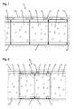
- a partition wall system 1 consisting of several sliding panels 3, shown.
- the sliding sashes 3 are formed as a full-glass wing with a disc 5 and have at the horizontal upper and lower edges of the disc 5 each have an edge profile 6, 7, which covers the side surfaces of the disc 5 in sections.
- the upper edge profile 6 is connected via suspension devices with roller carriage 8, the rollers 9 roll in a mounted on the building ceiling 11 running rail 10.
- the lower edge profile 7 may - not shown in this drawing - fittings for floor guidance and / or locking the sliding sash 3 with each other and / or with respect to the building floor 13 have.
- joins the movable partition 1 a stationary building wall 12 at. To release the covered by the movable partition wall 1 building the sliding panels 3 are displaced to the right, with a parking space for the sliding panel 3 is in the building wall 12.
- a sliding door system 2 consisting of two sliding sliding panels 3 in opposite directions and two the passage area laterally bounding fixed fields 4, shown.
- the sliding sash 3 are formed as all-glass wing with a disc 5 and have at the horizontal upper and lower edges of the disc 5 respectively in the corner regions edge profiles 6, 7, which cover the side surfaces of the disc 5 in sections.
- the upper edge profiles 6 are connected via suspension devices with roller carriage 8, the rollers 9 roll in a mounted on the building ceiling 11 running rail 10.
- the running rail 10 may be arranged a - not shown in this drawing - belt device, which are the two sliding sash 3 coupled together, for example in the sense of an opposing Move.
- the running rail 10 may also be arranged - not shown in this drawing - drive means for power-operated drive the sliding sash 3.
- the lower edge profiles 7 may - not shown in this drawing - fittings for floor guidance and / or locking the sliding sash 3 with each other and / or with respect to the building floor 13.
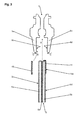
- frontal view is the upper edge region of the sliding leaf 3 of the partition wall system 1 according to Fig. 1 shown before mounting the disc 5 in the upper edge profile 6.
- the upper edge profile 6 has two side webs 6a, 6b, which on the top side - not shown here - can be connected to each other, for example as a one-piece body with a flexible section.
- an adjusting and fixing means for example at least one screw, the distance between the side webs 6a, 6b is adjustable relative to one another and can be fixed in the desired position, adapted to the thickness of the pane 5 used.
- the side webs 6a, 6b for receiving the upper edge region of the disk 5 facing each other contact surfaces 6c, 6d.
- the contact surfaces 6c, 6d each have a sawtooth-shaped surface.
- the pane 5 is formed as a laminated glass pane and consists of two outer layers of glass 5a, 5b, between which an intermediate layer 5e is embedded. Such slices 5 are not known to be subjected to high punctual pressure due to the relatively soft intermediate layer 5e. A direct, i. purely clamping holder of the disc 5 in the upper edge profile 6 is thus not possible.
- a holding profile 14 which is adhesively bonded to the side face 5d of the pane 5, for example by means of UV radiation curing adhesive, which has an extremely short curing time.
- the retaining profile 14 is formed in this embodiment L-shaped, wherein the short leg, the upper edge and the long leg, the side surface 5d of the disc 5 covers.
- the long leg of the holding profile 14 has on its side facing away from the disc 5 a contact surface 14a, which in the illustrated embodiment with a sawtooth-shaped surface, which is advantageously complementary to the surface of the contact surfaces 6c, 6d of the edge profile 6.
- the assembly steps are shown in the drawing with the dashed arrows A to C:
- the upper edge of the disc 5 is in the space between the side bars 6a, 6b of the upper edge profile. 6 introduced.
- the contact surface 14a of the holding profile 14 comes close to the corresponding contact surface 6d of the one, in the drawing right side web 6b of the upper edge profile 6 - assembly step A.
- the side webs 6a, 6b have between their contact surfaces 6c, 6d on such a large distance in that a securing profile 15 can subsequently be inserted from below into the intermediate space between the contact surface 6c of the other side web 6a and the side surface 5a of the disk 5 facing away from the retaining profile 14 - assembly step B. If appropriate, the securing profile 15 can be inserted with the Contact surface 6c of the edge profile 6 are glued. If appropriate, the assembly steps A and B can also be carried out in the reverse order.
- the side webs 6a, 6b of the edge profile 6 are moved towards each other by the adjusting and fixing means, so that the contact surfaces 6c, 6d of the edge profile 6 come into contact with the retaining profile 14 or with the securing profile 15, wherein the securing profile 15 in turn with of the holding profile 14 facing away from side surface 5c of the disc 5 comes into abutment - assembly step C.
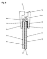
- frontal view is the upper edge region of the sliding leaf 3 of the sliding door system 2 according to Fig. 2 shown before mounting the disc 5 in the upper edge profile 6.
- the upper edge profile 6 is formed in two parts in this embodiment and has two side webs 6a, 6b, which are mutually connectable by means of mutually facing connecting webs 6e, 6f.
- the connecting webs 6e, 6f are formed on each of their mutually facing surfaces complementary to each other in a sawtooth-like manner, so that the side webs 6a, 6b can be connected to one another selectively in different distances depending on the thickness of the particular disk 5 used.
- the side webs 6a, 6b for receiving the upper edge region of the disk 5 facing each other contact surfaces 6c, 6d.
- the contact surfaces 6c, 6d each have a planar surface and an extension at the bottom. Accordingly, the contact surface 14a of the holding profile 14 of the disc 5 is formed with a flat surface.
- the assembly steps are shown in the drawing with the dashed arrows A to D:
- the connecting web 6f of the right in the drawing side bar 6b is in the desired position in the connecting web 6e of other side web 6a of the upper edge profile 6 hooked - assembly step A.
- the upper edge of the disc 5 is inserted into the space between the side bars 6a, 6b of the upper edge profile 6.
- the contact surface 14a of the retaining profile 14 comes close to the corresponding contact surface 6d of the one, in the drawing right side web 6b of the upper edge profile 6 - assembly step B.
- the side webs 6a, 6b have between their contact surfaces 6c, 6d on such a large distance in that subsequently in the intermediate space between the contact surface 6c of the other, in the drawing left side web 6a and the side facing away from the holding profile 14 5a the washer 5 a securing profile 15 can be inserted from below - assembly step C. If appropriate, the securing profile 15 can be glued to the contact surface 6c of the edge profile 6. If appropriate, the assembly steps B and C can also be carried out in the reverse order.
- the side webs 6a, 6b of the edge profile 6 are moved toward each other by the adjusting and fixing means formed as connecting screw 6g, so that the contact surfaces 6c, 6d of the edge profile 6 come into abutment with the retaining profile 14 or with the securing profile 15, wherein the Securing profile 15 in turn with the holding profile 14 facing away from side surface 5c of the disc 5 comes into engagement assembly step D.
Landscapes
- Engineering & Computer Science (AREA)
- Civil Engineering (AREA)
- Structural Engineering (AREA)
- Securing Of Glass Panes Or The Like (AREA)
Abstract
Description
- Die Erfindung betrifft einen Flügel einer Tür oder eines Fensters mit mindestens einer Glasscheibe nach dem Oberbegriff des Patentanspruchs 1 sowie ein Verfahren zur Montage eines Flügels nach dem Oberbegriff des Patentanspruchs 11.
- Aus der
DE 10 2004 007 568 A1 ist ein Flügel einer Tür mit einer Glasscheibe bekannt. Ein Randprofil dient zur hängenden Anordnung der Glasscheibe. Über Halteprofile wird die Verbindung der als Verbundglasscheibe ausgebildeten Scheibe mit dem Randprofil hergestellt. Das Randprofil ist im oberen Bereich der Scheibe angeordnet und weist zwei Seitenstege auf, welche den oberen Randbereich der Scheibe zumindest abschnittsweise überdecken und mit den Seitenflächen der Scheibe zusammenwirken, indem auf jeder Seitenfläche der Scheibe im Bereich ihrer horizontalen Oberkante jeweils ein Halteprofil aufgeklebt ist und die Halteprofile auf nach innen gerichteten Vorsprüngen der Seitenstege aufliegen. Diese Anordnung ist in der Handhabung bei der Montage aufwändig, da die Scheibe mit den beiden aufgeklebten Halteprofilen stirnseitig in das Randprofil eingeschoben werden muss. - Der Erfindung liegt die Aufgabe zugrunde, einen Flügel zu schaffen, der eine erleichterte Montage aufweist und auch die Verwendung bereits vorhandener Randprofile in Verbindung mit einer Verbundglasscheibe erlaubt.
- Die Aufgabe wird durch die Merkmale des Patentanspruchs 1 sowie des Patentanspruchs 11 gelöst.
- Die Unteransprüche bilden vorteilhafte Ausgestaltungsmöglichkeiten der Erfindung.
- Das Halteprofil ist lediglich auf einer Seitenfläche der Scheibe befestigt, während zwischen der anderen Seitenfläche der Scheibe und dem korrespondierenden Seitensteg des Randprofils ein separat einlegbares Sicherungsprofil angeordnet ist.
- Hierdurch wird die Montage des Flügels wesentlich vereinfacht, da die Scheibe mit dem einseitig angeklebten Halteprofil nicht stirnseitig in das Randprofil eingeschoben werden muss. Die mit dem Halteprofil versehene Oberkante der Scheibe kann von der jeweils handhabungsmäßig günstigsten Seite, insbesondere auch von unten zwischen die Seitenstege des Randprofils gebracht werden, woraufhin das separate Sicherungsprofil auf der dem Halteprofil abgewandten Seitenfläche der Scheibe zwischen den Seitensteg des Randprofils und die Scheibe eingelegt werden kann und abschließend dann die Seitenstege des Randprofils in ihre endgültige Montageposition aufeinander zu bewegt und dort fixiert werden.
- Die Seitenstege des Randprofils weisen jeweils eine Kontaktfläche auf, welche mit dem Halteprofil bzw. dem Sicherungsprofil zusammenwirkt.
- Die Kontaktfläche des Randprofils kann zumindest abschnittsweise eine sägezahnartige Oberfläche aufweisen, wodurch ein sicherer Halt der Scheibe in dem Randprofil erreicht wird. Alternativ oder zusätzlich kann die Kontaktfläche des Randprofils, ebenfalls zur Erzielung eines sicherer Halts der Scheibe in dem Randprofil, mindestens einen Vorsprung aufweisen.
- Das Halteprofil weist eine Kontaktfläche auf, welche mit der Kontaktfläche des Randprofils zusammenwirkt. Zur Erzielung eines sicheren Halts der Scheibe in dem Randprofil kann die Kontaktfläche des Halteprofils zumindest abschnittsweise eine zu der Kontaktfläche des Randprofils komplementäre Oberfläche aufweisen, beispielsweise sägezahnartig geformt.
- Alternativ oder zusätzlich können die Kontaktflächen das Randprofils und/oder des Halteprofils einen hohen Reibwert aufweisen, beispielsweise durch eine entsprechende Materialauswahl, Oberflächengestaltung und/oder Beschichtung. Das Halteprofil kann über eine Klebeverbindung an der Scheibe festgelegt werden. Diese Montageart zeichnet sich durch hohe Festigkeit aus und ist zudem einfach handhabbar, da an der Scheibe und an dem Halteprofil keinerlei Bohrungen oder dergleichen nachträglich angebracht werden müssen.
- Die einseitig angebrachten Halteprofile ermöglichen, dass die Klebeverbindung durch einen unter UV-Strahlung aushärtenden Klebstoff gebildet werden kann, wobei die UV-Strahlung durch die Scheibe hindurch auf den Klebstoff einwirkt. Derartige Klebstoffe zeichnen sich durch eine extrem schnelle Härtung aus, so dass die mit dem Halteprofil versehene Scheibe bereits unmittelbar nach dem Kleben des Halteprofils weiterverarbeitet, d.h. mit dem Tagprofil in Verbindung gebracht werden kann. Durch die Scheibe hindurch ist zudem eine Sichtkontrolle der Klebeverbindung möglich.
- Alternativ oder zusätzlich sind auch andere geeignete Befestigungsarten des Halteprofils an der Scheibe möglich.
- Im Nachfolgenden werden Ausführungsbeispiele in der Zeichnung anhand der Figuren näher erläutert.
- Dabei zeigen:
- Fig. 1
- eine bewegliche Trennwand mit erfindungsgemäßen Flügeln in sche- matischer Frontansicht;
- Fig. 2
- eine Schiebetüranlage mit erfindungsgemäßen Flügeln in schemati- scher Frontansicht;
- Fig. 3
- eine stirnseitige Ansicht des oberen Randbereichs eines Schiebeflü- gels der Trennwand gemäß
Fig. 1 vor der Montage der Scheibe im oberen Randprofil; - Fig. 4
- eine stirnseitige Ansicht gemäß
Fig. 3 nach erfolgter Montage der Scheibe im oberen Randprofil; - Fig. 5
- eine stirnseitige Ansicht des oberen Randbereichs eines Schiebeflü- gels der Schiebetüranlage gemäß
Fig. 2 vor der Montage der Scheibe im oberen Randprofil; - Fig. 6
- eine stirnseitige Ansicht gemäß
Fig. 5 nach erfolgter Montage der Scheibe im oberen Randprofil. - In der
Fig. 1 ist eine Trennwandanlage 1, bestehend aus mehreren Schiebeflügeln 3, dargestellt. Die Schiebeflügel 3 sind als Ganzglasflügel mit einer Scheibe 5 ausgebildet und weisen an den horizontalen Ober- und Unterkanten der Scheibe 5 jeweils ein Randprofil 6, 7 auf, welches die Seitenflächen der Scheibe 5 abschnittweise überdeckt. Das obere Randprofil 6 ist über Aufhängeeinrichtungen mit Rollenwagen 8 verbunden, deren Laufrollen 9 in einer an der Gebäudedecke 11 montierten Laufschiene 10 abrollen. Das untere Randprofil 7 kann - in dieser Zeichnung nicht dargestellte - Beschläge zur Bodenführung und/oder Verriegelung der Schiebeflügel 3 untereinander und/oder gegenüber dem Gebäudeboden 13 aufweisen. In der Zeichnung rechts schließt sich an die bewegliche Trennwand 1 eine ortsfeste Gebäudewand 12 an. Zum Freigeben der durch die bewegliche Trennwand 1 abgedeckten Gebäudeöffnung sind die Schiebeflügel 3 nach rechts verschiebbar, wobei sich im Bereich der Gebäudewand 12 ein Parkraum für die Schiebeflügel 3 befindet. - In der
Fig. 2 ist eine Schiebetüranlage 2, bestehend aus zwei gegenläufig verschiebbaren Schiebeflügeln 3 und zwei den Durchgangsbereich seitlich begrenzenden Festfeldern 4, dargestellt. Auch bei diesem Ausführungsbeispiel sind die Schiebeflügel 3 als Ganzglasflügel mit einer Scheibe 5 ausgebildet und weisen an den horizontalen Ober- und Unterkanten der Scheibe 5 jeweils in den Eckbereichen Randprofile 6, 7 auf, welche die Seitenflächen der Scheibe 5 abschnittweise überdecken. Die oberen Randprofile 6 sind über Aufhängeeinrichtungen mit Rollenwagen 8 verbunden, deren Laufrollen 9 in einer an der Gebäudedecke 11 montierten Laufschiene 10 abrollen. Im Bereich der Laufschiene 10 kann eine - in dieser Zeichnung nicht dargestellte - Riemeneinrichtung angeordnet sein, welche die beiden Schiebeflügel 3 miteinander koppelbar sind, z.B. im Sinne einer gegenläufigen Bewegung. Im Bereich der Laufschiene 10 kann außerdem eine - in dieser Zeichnung ebenfalls nicht dargestellte - Antriebseinrichtung zum fremdkraftbetätigten Antrieb der Schiebeflügel 3 angeordnet sein. Die unteren Randprofile 7 können - in dieser Zeichnung nicht dargestellte - Beschläge zur Bodenführung und/oder Verriegelung der Schiebeflügel 3 untereinander und/oder gegenüber dem Gebäudeboden 13 aufweisen. - In der in
Fig. 3 dargestellten, stirnseitigen Ansicht ist der obere Randbereich des Schiebeflügels 3 der Trennwandanlage 1 gemäßFig. 1 vor der Montage der Scheibe 5 in dem oberen Randprofil 6 gezeigt. Das obere Randprofil 6 weist zwei Seitenstege 6a, 6b auf, welche obenseitig - hier nicht dargestellt - miteinander verbunden sein können, z.B. als einstückiger Körper mit einem biegsamen Abschnitt. Mittels eines Verstell- und Fixiermittels, beispielsweise mindestens einer Schraube, ist der Abstand der Seitenstege 6a, 6b zueinander verstellbar und in der gewünschten Lage, angepasst an die Stärke der verwendeten Scheibe 5, fixierbar. - In ihrem unteren Bereich weisen die Seitenstege 6a, 6b zur Aufnahme des oberen Randbereichs der Scheibe 5 einander zugewandte Kontaktflächen 6c, 6d auf. In diesem Ausführungsbeispiel weisen die Kontaktflächen 6c, 6d jeweils eine sägezahnartig geformte Oberfläche auf.
- Die Scheibe 5 ist als Verbundglasscheibe ausgebildet und besteht aus zwei äußeren Schichten aus Glas 5a, 5b, zwischen denen eine Zwischenschicht 5e eingebettet ist. Derartigen Scheiben 5 dürfen bekanntlich aufgrund der relativ weichen Zwischenschicht 5e nicht mit hohem punktuellen Druck beaufschlagt werden. Eine direkte, d.h. rein klemmende Halterung der Scheibe 5 in dem oberen Randprofil 6 ist somit nicht möglich.
- Um die Scheibe dennoch, d.h. ohne Beschädigung ihrer Zwischenschicht 5e in dem oberen Randprofil 6 haltern zu können, ist sie in ihrem oberen Randbereich mit einem Halteprofil 14 versehen, welches auf die Seitenfläche 5d der Scheibe 5 aufgeklebt ist, beispielsweise mittels eines unter UV-Strahlung aushärtenden Klebstoffs, welcher eine extrem kurze Aushärtezeit aufweist. Das Halteprofil 14 ist in diesem Ausführungsbeispiel L-förmig ausgebildet, wobei der kurze Schenkel die Oberkante und der lange Schenkel die Seitenfläche 5d der Scheibe 5 überdeckt. Der lange Schenkel des Halteprofils 14 weist auf seiner von der Scheibe 5 abgewandten Seite eine Kontaktfläche 14a auf, welche im dargestellten Ausführungsbeispiel mit einer sägezahnartig geformten Oberfläche, welche vorteilhafterweise komplementär zu der Oberfläche der Kontaktflächen 6c, 6d des Randprofils 6 ausgebildet ist.
- Zur Montage der Scheibe 5 in dem oberen Randprofil 6 werden folgende Schritte durchlaufen (die Montageschritte sind in der Zeichnung mit den gestrichelten Pfeilen A bis C dargestellt): Die Oberkante der Scheibe 5 wird in den Zwischenraum zwischen den Seitenstegen 6a, 6b des oberen Randprofils 6 eingeführt. Hierbei gelangt die Kontaktfläche 14a des Halteprofils 14 in die Nähe der korrespondierenden Kontaktfläche 6d des einen, in der Zeichnung rechten Seitenstegs 6b des oberen Randprofils 6 - Montageschritt A. Die Seitenstege 6a, 6b weisen hierbei zwischen ihren Kontaktflächen 6c, 6d einen so großen Abstand auf, dass anschließend in den Zwischenraum zwischen der Kontaktfläche 6c des anderen, in der Zeichnung linken Seitenstegs 6a und der dem Halteprofil 14 abgewandten Seitenfläche 5a der Scheibe 5 ein Sicherungsprofil 15 von unten her eingelegt werden kann - Montageschritt B. Gegebenenfalls kann das Sicherungsprofil 15 mit der Kontaktfläche 6c des Randprofils 6 verklebt werden. Die Montageschritte A und B können gegebenenfalls auch in umgekehrter Reihenfolge erfolgen. Anschließend werden die Seitenstege 6a, 6b des Randprofils 6 durch das Verstell- und Fixiermittel aufeinander zu bewegt, so dass die Kontaktflächen 6c, 6d des Randprofils 6 mit dem Halteprofil 14 bzw. mit dem Sicherungsprofil 15 in Anlage kommen, wobei das Sicherungsprofil 15 seinerseits mit der dem Halteprofil 14 abgewandten Seitenfläche 5c der Scheibe 5 in Anlage kommt - Montageschritt C.
- Wesentlich ist, dass durch die Seitenstege 6a, 6b des Randprofils 6 in der endgültigen, in
Fig. 4 dargestellten Position kein wesentlicher Druck in horizontaler Richtung auf die Scheibe 5 ausgeübt wird, so dass eine Beschädigung der Zwischenschicht 5e der Scheibe 5 ausgeschlossen ist. Durch die miteinander in Berührung stehenden Kontaktflächen 6d, 14a des Randprofils 6 bzw. des Halteprofils 14, bei diesem Ausführungsbeispiel konkret durch das Ineinandergreifenden der sägezahnartig geformten Konturen der Kontaktflächen 6d, 14a, ist die Scheibe 5 dennoch zuverlässig in dem Randprofil 6 gehaltert. - In der in
Fig. 5 dargestellten, stirnseitigen Ansicht ist der obere Randbereich des Schiebeflügels 3 der Schiebetüranlage 2 gemäßFig. 2 vor der Montage der Scheibe 5 in dem oberen Randprofil 6 gezeigt. Das obere Randprofil 6 ist in diesem Ausführungsbeispiel zweiteilig ausgebildet und weist zwei Seitenstege 6a, 6b auf, welche mittels einander zugewandter Verbindungsstege 6e, 6f miteinander verbindbar sind. Die Verbindungsstege 6e, 6f sind an ihren einander zugewandten Flächen zueinander komplementär jeweils sägezahnartig geformt, so dass das sich die Seitenstege 6a, 6b wahlweise in verschiedenen, von der Stärke der jeweils verwendeten Scheibe 5 abhängigen Abständen miteinander verbinden lassen. In ihrem unteren Bereich weisen die Seitenstege 6a, 6b zur Aufnahme des oberen Randbereichs der Scheibe 5 einander zugewandte Kontaktflächen 6c, 6d auf. In diesem Ausführungsbeispiel weisen die Kontaktflächen 6c, 6d jeweils eben geformte Oberfläche und unten einen Fortsatz auf. Entsprechend ist auch die Kontaktfläche 14a des Halteprofils 14 der Scheibe 5 mit einer ebenen Oberfläche ausgebildet. - Zur Montage der Scheibe 5 in dem oberen Randprofil 6 werden folgende Schritte durchlaufen (die Montageschritte sind in der Zeichnung mit den gestrichelten Pfeilen A bis D dargestellt): Der Verbindungssteg 6f des in der Zeichnung rechten Seitenstegs 6b wird in gewünschter Position in den Verbindungssteg 6e des anderen Seitenstegs 6a des oberen Randprofils 6 eingehängt - Montageschritt A. Anschließend wird die Oberkante der Scheibe 5 in den Zwischenraum zwischen den Seitenstegen 6a, 6b des oberen Randprofils 6 eingeführt. Hierbei gelangt die Kontaktfläche 14a des Halteprofils 14 in die Nähe der korrespondierenden Kontaktfläche 6d des einen, in der Zeichnung rechten Seitenstegs 6b des oberen Randprofils 6 - Montageschritt B. Die Seitenstege 6a, 6b weisen hierbei zwischen ihren Kontaktflächen 6c, 6d einen so großen Abstand auf, dass anschließend in den Zwischenraum zwischen der Kontaktfläche 6c des anderen, in der Zeichnung linken Seitenstegs 6a und der dem Halteprofil 14 abgewandten Seitenfläche 5a der Scheibe 5 ein Sicherungsprofil 15 von unten her eingelegt werden kann - Montageschritt C. Gegebenenfalls kann das Sicherungsprofil 15 mit der Kontaktfläche 6c des Randprofils 6 verklebt werden. Die Montageschritte B und C können gegebenenfalls auch in umgekehrter Reihenfolge erfolgen. Anschließend werden die Seitenstege 6a, 6b des Randprofils 6 durch das als Verbindungsschraube 6g ausgebildete Verstell- und Fixiermittel aufeinander zu bewegt, so dass die Kontaktflächen 6c, 6d des Randprofils 6 mit dem Halteprofil 14 bzw. mit dem Sicherungsprofil 15 in Anlage kommen, wobei das Sicherungsprofil 15 seinerseits mit der dem Halteprofil 14 abgewandten Seitenfläche 5c der Scheibe 5 in Anlage kommt- Montageschritt D.
- Wesentlich ist, dass durch die Seitenstege 6a, 6b des Randprofils 6 in der endgültigen, in
Fig. 6 dargestellten Position kein wesentlicher Druck in horizontaler Richtung auf die Scheibe 5 ausgeübt wird, so dass eine Beschädigung der weichen Zwischenschicht 5e der Scheibe 5 ausgeschlossen ist. Durch die miteinander in Berührung stehenden Kontaktflächen 6d, 14a des Randprofils 6 bzw. des Halteprofils 14, bei diesem Ausführungsbeispiel konkret durch das Aufliegen des Halteprofils auf dem Fortsatz der Kontaktfläche 6d des Randprofils 6, ist die Scheibe 5 dennoch zuverlässig in dem Randprofil 6 gehaltert. -
- 1
- Trennwandanlage
- 2
- Schiebetüranlage
- 3
- Schiebeflügel
- 4
- Festfeld
- 5
- Scheibe
- 5a
- Glas
- 5b
- Glas
- 5c
- Seitenfläche
- 5d
- Seitenfläche
- 5e
- Zwischenschicht
- 6
- Randprofil
- 6a
- Seitensteg
- 6b
- Seitensteg
- 6c
- Kontaktfläche
- 6d
- Kontaktfläche
- 6e
- Verbindungssteg
- 6f
- Verbindungssteg
- 6g
- Verbindungsschraube
- 7
- Randprofil
- 8
- Rollenwagen
- 9
- Laufrolle
- 10
- Laufschiene
- 11
- Gebäudedecke
- 12
- Gebäudewand
- 13
- Gebäudeboden
- 14
- Halteprofil
- 14a
- Kontaktfläche
- 15
- Sicherungsprofil
- A
- Montageschritt
- B
- Montageschritt
- C
- Montageschritt
- D
- Montageschritt
Claims (11)
- Flügel für Türen, Fenster oder dergleichen,
mit mindestens einer Scheibe (5),
mit einem Randprofil (6) zur hängenden Anordnung der Scheibe (5), und mit mindestens einem Halteprofil (14) zur Verbindung der Scheibe (5) mit dem Randprofil (6),
wobei die Scheibe (5) vorzugsweise als Verbundglasscheibe ausgebildet ist, und
wobei das Randprofil (6) im oberen Bereich der Scheibe (5) angeordnet ist und zwei Seitenstege (6a, 6b) aufweist, welche den oberen Randbereich der Scheibe (5) zumindest abschnittsweise überdecken und mit den Seitenflächen (5c, 5d) der Scheibe (5) zusammenwirken,
dadurch gekennzeichnet,
dass das Halteprofil (14) lediglich auf einer Seitenfläche (5d) der Scheibe (5) befestigt ist, während zwischen der anderen Seitenfläche (5c) der Scheibe (5) und dem korrespondierenden Seitensteg (6b) des Randprofils (6) ein separat einlegbares Sicherungsprofil (15) angeordnet ist. - Flügel nach Anspruch 1,
dadurch gekennzeichnet, dass die Seitenstege (6a, 6b) des Randprofils (6) jeweils eine Kontaktfläche (6c, 6d) aufweisen, welche mit dem Halteprofil (14) bzw. dem Sicherungsprofil (15) zusammenwirkt. - Flügel nach Anspruch 2,
dadurch gekennzeichnet, dass die Kontaktfläche (6c, 6d) des Randprofils (6) zumindest abschnittsweise eine sägezahnartige Oberfläche aufweist. - Flügel nach Anspruch 2,
dadurch gekennzeichnet, dass die Kontaktfläche (6c, 6d) des Randprofils (6) mindestens einen Vorsprung aufweist. - Flügel nach Anspruch 2,
dadurch gekennzeichnet, dass die Kontaktfläche (6c, 6d) des Randprofils (6) einen hohen Reibwert aufweist. - Flügel nach Anspruch 1,
dadurch gekennzeichnet, dass das Halteprofil (14) eine Kontaktfläche (14a) aufweist, welche mit der Kontaktfläche (6c, 6d) des Randprofils (6) zusammenwirkt. - Flügel nach Anspruch 6,
dadurch gekennzeichnet, dass die Kontaktfläche (14a) des Halteprofils (14) zumindest abschnittsweise eine zu der Kontaktfläche (6c, 6d) des Randprofils (6) komplementäre Oberfläche aufweist. - Flügel nach Anspruch 6,
dadurch gekennzeichnet, dass die Kontaktfläche (14a) des Halteprofils (14) einen hohen Reibwert aufweist. - Flügel nach Anspruch 1,
dadurch gekennzeichnet, dass das Halteprofil (14) über eine Klebeverbindung an der Scheibe (5) montiert wird. - Flügel nach Anspruch 9,
dadurch gekennzeichnet, dass die Klebeverbindung durch einen unter UV-Strahlung aushärtenden Klebstoff gebildet wird, wobei die UV-Strahlung durch die Scheibe (5) hindurch auf den Klebstoff im Sinne seiner Aushärtung einwirkt. - Verfahren zur Montage eines Flügels für Türen, Fenster oder dergleichen, mit mindestens einer Scheibe (5),
mit einem Randprofil (6) zur hängenden Anordnung der Scheibe (5), und mit mindestens einem Halteprofil (14) zur Verbindung der Scheibe (5) mit dem Randprofil (6),
wobei die Scheibe (5) vorzugsweise als Verbundglasscheibe ausgebildet ist, und
wobei das Randprofil (6) im oberen Bereich der Scheibe (5) angeordnet ist und zwei Seitenstege (6a, 6b) aufweist, welche den oberen Randbereich der Scheibe (5) überdecken und mit den Seitenflächen (5c, 5d) der Scheibe (5) zusammenwirken,
dadurch gekennzeichnet, dass folgende Montageschritte durchlaufen werden: Befestigen des Halteprofils (14) lediglich auf einer Seitenfläche (5d) der Scheibe (5), Einlegen und vorzugsweise Ankleben mindestens eines separaten Sicherungsprofils (15) an einer Kontaktfläche (6c) des mit der anderen Seitenfläche (5c) der Scheibe (5) korrespondierenden Seitenstegs (6b) des Randprofils (6), Einführen der Oberkante der Scheibe (5) in den Zwischenraum zwischen den Seitenstegen (6a, 6b) des oberen Randprofils 6, Verringern des Abstands zwischen den Seitenstegen (6a, 6b) des Randprofils (6).
Applications Claiming Priority (1)
| Application Number | Priority Date | Filing Date | Title |
|---|---|---|---|
| DE102009027240A DE102009027240A1 (de) | 2009-06-26 | 2009-06-26 | Flügel und Verfahren zur Montage eines Flügels |
Publications (2)
| Publication Number | Publication Date |
|---|---|
| EP2281992A2 true EP2281992A2 (de) | 2011-02-09 |
| EP2281992A3 EP2281992A3 (de) | 2014-07-30 |
Family
ID=42937083
Family Applications (1)
| Application Number | Title | Priority Date | Filing Date |
|---|---|---|---|
| EP10167284.8A Withdrawn EP2281992A3 (de) | 2009-06-26 | 2010-06-25 | Ganzglasflügel und Verfahren zur Montage eines Ganzglasflügels |
Country Status (2)
| Country | Link |
|---|---|
| EP (1) | EP2281992A3 (de) |
| DE (1) | DE102009027240A1 (de) |
Cited By (1)
| Publication number | Priority date | Publication date | Assignee | Title |
|---|---|---|---|---|
| CN109798056A (zh) * | 2019-02-21 | 2019-05-24 | 安徽鑫煜门窗有限公司 | 一种方便固定安装的玻璃钢门 |
Citations (1)
| Publication number | Priority date | Publication date | Assignee | Title |
|---|---|---|---|---|
| DE102004007568A1 (de) | 2003-02-24 | 2004-09-02 | Jens Mittag | Vorrichtung zur hängenden Anordnung einer Sicherheitsglasscheibe an einem Trägerprofil |
Family Cites Families (4)
| Publication number | Priority date | Publication date | Assignee | Title |
|---|---|---|---|---|
| DE4404653C2 (de) * | 1994-02-14 | 1996-12-19 | Temotrans Bv | Klemmprofil, insbesondere für eine Glasscheibe |
| DE9415463U1 (de) * | 1994-09-23 | 1994-11-17 | Ta-Only Enterprise Corp., Kaohsiung | Türrahmen |
| WO2007048266A1 (de) * | 2005-10-27 | 2007-05-03 | Kaba Gilgen Ag | Glasflügel für türen, tore, wände und fenster |
| DE102008004751B3 (de) * | 2008-01-16 | 2009-08-06 | Geze Gmbh | Klemmbeschlag |
-
2009
- 2009-06-26 DE DE102009027240A patent/DE102009027240A1/de not_active Withdrawn
-
2010
- 2010-06-25 EP EP10167284.8A patent/EP2281992A3/de not_active Withdrawn
Patent Citations (1)
| Publication number | Priority date | Publication date | Assignee | Title |
|---|---|---|---|---|
| DE102004007568A1 (de) | 2003-02-24 | 2004-09-02 | Jens Mittag | Vorrichtung zur hängenden Anordnung einer Sicherheitsglasscheibe an einem Trägerprofil |
Cited By (2)
| Publication number | Priority date | Publication date | Assignee | Title |
|---|---|---|---|---|
| CN109798056A (zh) * | 2019-02-21 | 2019-05-24 | 安徽鑫煜门窗有限公司 | 一种方便固定安装的玻璃钢门 |
| CN109798056B (zh) * | 2019-02-21 | 2024-05-17 | 安徽鑫煜门窗有限公司 | 一种方便固定安装的玻璃钢门 |
Also Published As
| Publication number | Publication date |
|---|---|
| EP2281992A3 (de) | 2014-07-30 |
| DE102009027240A1 (de) | 2010-12-30 |
Similar Documents
| Publication | Publication Date | Title |
|---|---|---|
| DE3739912C2 (de) | ||
| WO2005068764A1 (de) | Rahmen für eine schiebetür oder ein schiebefenster | |
| WO2010079125A1 (de) | Profilsystem für eine schiebetür | |
| EP2113625B1 (de) | Niedrigenergiefenster | |
| EP4092240A1 (de) | Neue klebetechnik zur montage von fenstern | |
| EP3034735B1 (de) | Schiebewandsystem mit mindestens einem Türflügelelement mit einer Glasscheibe und Verfahren zum Befestigen der Glasscheibe im Schiebewandsystem | |
| EP3181796B1 (de) | Spaltabdichtungselement für schiebetüren, und spaltabdichtungsanordnung | |
| EP2327855B1 (de) | Isolierglaseinheit und Tragkonstruktion mit mindestens einer derartigen Isolierglaseinheit | |
| EP2476852B1 (de) | Montagehilfseinrichtung für einen Flügel einer Tür, eines Fensters oder dergleichen | |
| DE102004007568B4 (de) | Vorrichtung zur hängenden Anordnung einer Sicherheitsglasscheibe an einem Trägerprofil | |
| EP2754836A2 (de) | Haustürflügel mit Klipsverbindung | |
| DE3832178A1 (de) | Klebeverbindung von glasscheiben, fassaden-, wandelementen u. dgl. | |
| DE102009027240A1 (de) | Flügel und Verfahren zur Montage eines Flügels | |
| DE202006001767U1 (de) | Fensterheber für ein Kraftfahrzeug | |
| WO2017072288A1 (de) | Scheibenanordnung, insbesondere karosserie-scheibenanordnung | |
| DE10119640C2 (de) | Rahmenlose Trennwand | |
| EP3034742A1 (de) | Schiebewandsystem mit geringstem Anschubmoment | |
| EP3034739A1 (de) | Schiebewandsystem mit optimierter Dichtung | |
| EP3034741B1 (de) | Schiebewandsystem mit verbessertem akustischem Verhalten | |
| EP2644792B1 (de) | Wandteil mit einer Verbundglasscheibe und mit einer Vorrichtung zum Verbinden von Wandteilen | |
| EP3034743B1 (de) | Schiebewandsystem mit Sicherungsvorrichtung | |
| EP1574632B1 (de) | Trockenbauwand | |
| EP3034721B1 (de) | Schiebewandsystem mit verriegelungsmechanismus und anzeigeeinrichtung zum anzeigen eines verriegelungszustands eines türflügelelements | |
| EP1980702B1 (de) | Rahmenkonstruktion für Fenster und/oder Türen | |
| DE102006054427A1 (de) | Alu-Kunststoff-Fenster mit Klebebandfixierung |
Legal Events
| Date | Code | Title | Description |
|---|---|---|---|
| PUAI | Public reference made under article 153(3) epc to a published international application that has entered the european phase |
Free format text: ORIGINAL CODE: 0009012 |
|
| AK | Designated contracting states |
Kind code of ref document: A2 Designated state(s): AL AT BE BG CH CY CZ DE DK EE ES FI FR GB GR HR HU IE IS IT LI LT LU LV MC MK MT NL NO PL PT RO SE SI SK SM TR |
|
| AX | Request for extension of the european patent |
Extension state: BA ME RS |
|
| PUAL | Search report despatched |
Free format text: ORIGINAL CODE: 0009013 |
|
| AK | Designated contracting states |
Kind code of ref document: A3 Designated state(s): AL AT BE BG CH CY CZ DE DK EE ES FI FR GB GR HR HU IE IS IT LI LT LU LV MC MK MT NL NO PL PT RO SE SI SK SM TR |
|
| AX | Request for extension of the european patent |
Extension state: BA ME RS |
|
| RIC1 | Information provided on ipc code assigned before grant |
Ipc: E06B 3/46 20060101ALI20140624BHEP Ipc: E06B 3/54 20060101ALI20140624BHEP Ipc: E06B 3/02 20060101AFI20140624BHEP |
|
| 17P | Request for examination filed |
Effective date: 20150127 |
|
| RBV | Designated contracting states (corrected) |
Designated state(s): AL AT BE BG CH CY CZ DE DK EE ES FI FR GB GR HR HU IE IS IT LI LT LU LV MC MK MT NL NO PL PT RO SE SI SK SM TR |
|
| 17Q | First examination report despatched |
Effective date: 20160518 |
|
| STAA | Information on the status of an ep patent application or granted ep patent |
Free format text: STATUS: THE APPLICATION HAS BEEN WITHDRAWN |
|
| 18W | Application withdrawn |
Effective date: 20170505 |