EP2281664A2 - Vormontierte Vorrichtung - Google Patents
Vormontierte Vorrichtung Download PDFInfo
- Publication number
- EP2281664A2 EP2281664A2 EP10168714A EP10168714A EP2281664A2 EP 2281664 A2 EP2281664 A2 EP 2281664A2 EP 10168714 A EP10168714 A EP 10168714A EP 10168714 A EP10168714 A EP 10168714A EP 2281664 A2 EP2281664 A2 EP 2281664A2
- Authority
- EP
- European Patent Office
- Prior art keywords
- assembly device
- elements
- wall elements
- wall
- filter housing
- Prior art date
- Legal status (The legal status is an assumption and is not a legal conclusion. Google has not performed a legal analysis and makes no representation as to the accuracy of the status listed.)
- Granted
Links
- 238000011990 functional testing Methods 0.000 description 2
- 238000004519 manufacturing process Methods 0.000 description 2
- XAGFODPZIPBFFR-UHFFFAOYSA-N aluminium Chemical compound [Al] XAGFODPZIPBFFR-UHFFFAOYSA-N 0.000 description 1
- 229910052782 aluminium Inorganic materials 0.000 description 1
- 230000015572 biosynthetic process Effects 0.000 description 1
- 230000000903 blocking effect Effects 0.000 description 1
- 238000001704 evaporation Methods 0.000 description 1
- 239000000446 fuel Substances 0.000 description 1
- 238000002347 injection Methods 0.000 description 1
- 239000007924 injection Substances 0.000 description 1
- 238000009434 installation Methods 0.000 description 1
- 238000012423 maintenance Methods 0.000 description 1
- 239000000203 mixture Substances 0.000 description 1
- 238000003908 quality control method Methods 0.000 description 1
- 238000005476 soldering Methods 0.000 description 1
Images



Classifications
-
- B—PERFORMING OPERATIONS; TRANSPORTING
- B25—HAND TOOLS; PORTABLE POWER-DRIVEN TOOLS; MANIPULATORS
- B25F—COMBINATION OR MULTI-PURPOSE TOOLS NOT OTHERWISE PROVIDED FOR; DETAILS OR COMPONENTS OF PORTABLE POWER-DRIVEN TOOLS NOT PARTICULARLY RELATED TO THE OPERATIONS PERFORMED AND NOT OTHERWISE PROVIDED FOR
- B25F5/00—Details or components of portable power-driven tools not particularly related to the operations performed and not otherwise provided for
- B25F5/02—Construction of casings, bodies or handles
Definitions
- the invention relates to a preassemblable device of elements, in particular a tool device or a hand tool device, according to the preamble of claim 1.
- Such devices include an air cleaner and an intake manifold and a carburetor for operating the fuel-powered propulsion engine. This air is sucked in through the air filter and fed from there by means of the intake manifold to the carburetor.
- the intake manifold is preferably made of plastic or cast aluminum for weight reasons.
- the intake manifold advantageously has a curved shape, since the openings on the carburetor are usually arranged approximately horizontally to the inlet of the intake air and therefore the intake flow has to be deflected in this regard.
- intake manifold injection In some types of engines in the intake manifold and the mixture formation takes place, which is also referred to as intake manifold injection. That is, in the intake manifold, the air is mixed with the evaporating fuel so as to generate a combustible gas that the engine sucks.
- the control of the device is usually by means of a hand-operated unit comprising a handle for holding the device and a throttle handle for controlling the motor.
- a tank-handle unit in which the carburetor of the device is firmly integrated.
- the assembly of the permanently integrated into the tank gas mechanics and the carburetor because of the numerous joints consuming, because these joints must be connected and the respective positioning must be very accurate, otherwise a functionality can be disturbed or prevented.
- a preassemblable device of elements in particular a tool device or a hand tool device, is provided, wherein the device comprises at least one intake manifold, a filter bottom and / or a carburetor preferably with a carburetor wall, wherein furthermore a Holding structure for receiving actuators is provided.
- the preassemblable device is further developed in that the device further comprises a filter bottom or a filter housing. Furthermore, it is advantageous if the filter housing is approximately rectangular in cross-section.
- the intake manifold or filter bottom or the filter tongue has the holding structure on one of its sides.
- the holding structure has two wall elements which are arranged approximately parallel to one another and are spaced apart from one another.
- the spaced wall elements receive the actuators between them.
- a handle can be produced which protects the sensitive mechanism.
- the spaced wall elements receive the actuating or operating elements by receiving and supporting axes in openings of the wall elements between them. This also contributes to the fact that a handle can be produced which protects the sensitive mechanism and still allows a smooth operation of the operating or operating elements.
- the axes are arranged in openings of the wall elements, wherein a first axis is arranged in the front lower region of the wall elements.
- the axes are arranged in openings of the wall elements, wherein a second axis is arranged in the rear upper region of the wall elements.
- the actuation elements comprise a throttle grip and / or a lock button.
- FIGS. 1 to 5 show an intake manifold 1 with a filter bottom 2 and a carburetor 3 with a carburetor 4.
- the filter bottom 2 is received in an approximately rectangular filter housing 5, which has on its one side 6 a support structure 7, which serves to form a handle 8 and / or actuators 9,10 record.
- the support structure 7 consists of two approximately opposite wall elements 11, 12, which have a shape in a side view, which is a handle comes close. Between these wall elements 11,12, the actuating elements 9,10 each about an axis 13, 14 are rotatably received and arranged and arranged.
- the elements 9, 10 form a throttle grip 9 and a locking key 10 for blocking or releasing the throttle grip 9.
- the throttle grip is held pivotable about the axis 13 and the locking key 10 is held pivotable about the axis 14.
- the axle 13 is arranged in the front area and at the lower area of the handle or the wall elements and the axle 14 is arranged at its end area and in its upper area.
- the embodiment according to the invention makes it possible to form a component structure which can be arranged or fastened to the intake manifold, to the filter base with the intake manifold and / or to the gasifier wall.
- This component structure is capable of receiving the throttle grip and / or the lock key, and this pre-assembled unit forms a subassembly for mounting with a handle tank unit.
- the unit according to the invention which is preassembled with the controls of the throttle grip and the lock button, this can be advantageously pre-assembled and also tested, so that a function and quality control can be performed already in this production study.
Landscapes
- Engineering & Computer Science (AREA)
- Mechanical Engineering (AREA)
- Control Of Throttle Valves Provided In The Intake System Or In The Exhaust System (AREA)
- Lubrication Details And Ventilation Of Internal Combustion Engines (AREA)
- Filtering Of Dispersed Particles In Gases (AREA)
- Processing And Handling Of Plastics And Other Materials For Molding In General (AREA)
- Lining Or Joining Of Plastics Or The Like (AREA)
- Catching Or Destruction (AREA)
Abstract
Description
- Die Erfindung betrifft eine vormontierbare Vorrichtung von Elementen, insbesondere einer Werkzeugvorrichtung oder einer Handwerkzeugvorrichtung, nach dem Oberbegriff von Anspruch 1.
- Bei Werkzeugvorrichtungen oder bei Handwerkzeugvorrichtungen aber auch bei anderweitigen Vorrichtungen findet man im Stand der Technik auch Vorrichtungen vor, die einen kraftstoffbetriebenen Antriebsmotor aufweisen.
- Solche Vorrichtungen weisen zum Betreiben des kraftstoffbetriebenen Antriebsmotors einen Luftfilter und einen Ansaugkrümmer und einen Vergaserauf. Dabei wird Luft über den Luftfilter angesaugt und von dort mittels des Ansaugkrümmers dem Vergaser zugeleitet. Der Ansaugkrümmer besteht vorzugsweise aus Gewichtsgründen aus Kunststoff oder aus Aluminiumguss. Der Ansaugkrümmer hat dabei vorteilhaft eine gekrümmte Form, da üblicher Weise die Öffnungen am Vergaser zum Einlass der Ansaugluft in etwa horizontal angeordnet sind und daher der Ansaugstrom diesbezüglich umgelenkt werden muss. Bei manchen Motorentypen findet im Ansaugkrümmer auch die Gemischbildung statt, was auch als Saugrohreinspritzung bezeichnet wird. Das heißt, dass im Ansaugkrümmer die Luft mit dem verdampfenden Kraftstoff vermischt wird, um so ein brennbares Gas zu erzeugen, das der Motor ansaugt.
- Die Steuerung der Vorrichtung erfolgt üblicher Weise mittels einer handbetätigbaren Einheit, die einen Griff zum Halten der Vorrichtung und einen Gasgriff zur Steuerung des Motors umfasst.
- Üblicher Weise ist bei heutigen Vorrichtungen, wie bei Trennschleifem, eine Tank-Griff-Einheit vorgesehen, in welcher der Vergaser der Vorrichtung fest integriert ist. Dabei ist die Montage der fest in den Tank integrierten Gasmechanik und des Vergasers aufgrund der zahlreichen Verbindungsstellen aufwändig, weil diese Verbindungsstellen verbunden sein müssen und dabei die jeweilige Positionierung sehr genau erfolgen muss, weil ansonsten eine Funktionsfähigkeit gestört oder verhindert werden kann.
- Dabei ist es weiterhin nachteilig, dass eine Funktionsprüfung erst im vollständig montierten Zustand und somit nach der aufwändigen Montage des kompletten Gerätes erfolgen kann.
- Es ist die Aufgabe der Erfindung, eine vormontierbare Vorrichtung von Elementen insbesondere einer Werkzeugvorrichtung oder einer Handwerkzeugvorrichtung zu schaffen, die leichter herstellbar ist und die auch eine weitestgehende Funktionsprüfung vor der vollständigen Montage erlaubt.
- Dies wird erreicht mit den Merkmalen von Anspruch 1, wonach eine vormontierbare Vorrichtung von Elementen, insbesondere einer Werkzeugvorrichtung oder einer Handwerkzeugvorrichtung, geschaffen wird, wobei die Vorrichtung zumindest einen Ansaugkrümmer, einen Filterboden und/oder einen Vergaser vorzugsweise mit einer Vergaserwand umfasst, wobei weiterhin eine Haltestruktur zur Aufnahme von Betätigungselementen vorgesehen ist.
- Dabei ist erfindungsgemäß vorteilhaft, wenn die vormontierbare Vorrichtung dadurch weitergebildet wird, dass die Vorrichtung weiterhin einen Filterboden oder ein Filtergehäuse umfasst. Weiterhin ist es vorteilhaft, wenn das Filtergehäuse im Querschnitt etwa rechteckig ausgebildet ist.
- Auch ist es zweckmäßig, wenn der Ansaugkrümmer oder Filterboden oder die Filterzunge an einer seiner Seiten die Haltestruktur aufweist.
- Besonders vorteilhaft ist es, wenn die Haltestruktur zwei etwa parallel zueinander angeordnete und beabstandete Wandelemente aufweist.
- Weiterhin ist es vorteilhaft, wenn die beabstandeten Wandelemente die Betätigungselemente zwischen sich aufnehmen. Dadurch kann ein Griff erzeugt werden, welcher die empfindliche Mechanik schützt.
- Auch ist es vorteilhaft, wenn die beabstandeten Wandelemente die Betätigungs-oder Bedienelemente durch Aufnahme und Lagerung von Achsen in Öffnungen der Wandelemente zwischen sich aufnehmen. Auch dies trägt dazu bei, dass ein Griff erzeugt werden kann, welcher die empfindliche Mechanik schützt und dennoch eine leichtgängige Funktion der Betätigungs- oder Bedienelemente erlaubt.
- Zweckmäßig ist es weiterhin, wenn die Achsen in Öffnungen der Wandelemente angeordnet sind, wobei eine erste Achse im vorderen unteren Bereich der Wandelemente angeordnet ist.
- Auch ist es zweckmäßig, wenn die Achsen in Öffnungen der Wandelemente angeordnet sind, wobei eine zweite Achse im hinteren oberen Bereich der Wandelemente angeordnet ist.
- Erfindungsgemäß ist es besonders vorteilhaft, wenn die Betätigungselemente ein Gasgriff und/oder eine Sperrtaste umfassen.
- Weitere erfindungsgemäße Vorteile werden in den Unteransprüchen und in der nachfolgenden Figurenbeschreibung beschrieben.
- Nachstehend wird die Erfindung auf der Grundlage eines Ausführungsbeispiels anhand der Zeichnungen näher erläutert. Es zeigen:
-
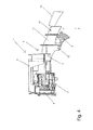
Fig. 1 eine schematische Ansicht einer erfindungsgemäßen Vorrichtung, -
Fig. 2 eine schematische Ansicht einer erfindungsgemäßen Vorrichtung mit demontiertem Gasgriff und Sperrtaste, -
Fig. 3 eine schematische Ansicht von oben von einer erfindungsgemäßen Vorrichtung, -
Fig. 4 eine schematische Ansicht von der Seite von einer erfindungsgemäßen Vorrichtung, und -
Fig. 5 eine schematische Ansicht von unten von einer erfindungsgemäßen Vorrichtung. - Die
Figuren 1 bis 5 zeigen einen Ansaugkrümmer 1 mit einem Filterboden 2 und einem Vergaser 3 mit einer Vergaserwand 4. Dabei ist der Filterboden 2 in ein etwa rechteckiges Filtergehäuse 5 aufgenommen, das an seiner einen Seite 6 eine Haltestruktur 7 aufweist, welche dazu dient, einen Griff 8 zu bilden und/oder Betätigungselemente 9,10 aufzunehmen. - Die Haltestruktur 7 besteht dabei aus zwei sich etwa gegenüberliegenden Wandelementen 11, 12, die in einer Seitenansicht eine Form aufweisen, die einem Griff nahe kommt. Zwischen diesen Wandelementen 11,12 sind die Betätigungselemente 9,10 jeweils um eine Achse 13, 14 verdrehbar bzw. schwenkbar aufgenommen und angeordnet.
- Dabei bilden die Elemente 9, 10 einen Gasgriff 9 und eine Sperrtaste 10 zur Blockierung bzw. zur Freigabe des Gasgriffs 9. Der Gasgriff ist dabei um die Achse 13 verschwenkbar gehalten und die Sperrtaste 10 ist um die Achse 14 schwenkbar gehalten.
- Wie es in den Figuren zu erkennen ist, ist die Achse 13 im vorderen Bereich und am unteren Bereich des Griffs bzw. der Wandelemente angeordnet und die Achse 14 ist an ihrem Endbereich und in ihrem oberen Bereich angeordnet.
- Durch die erfindungsgemäße Ausgestaltung ist es möglich, dass eine Bauteilstruktur gebildet werden kann, welche an den Ansaugkrümmer, an den Filterboden mit dem Ansaugkrümmer und/oder an die Vergaserwand angeordnet oder befestigt werden kann. Diese Bauteilstruktur ist in der Lage den Gasgriff und/oder die Sperrtaste aufzunehmen und, wobei diese vormontierbare Einheit eine Untereinheit zur Montage mit einer Griff-Tank-Einheit bildet.
- Durch die erfindungsgemäße Einheit, die mit den Bedienelementen des Gasgriffs und der Sperrtaste vormontierbar ist, kann diese vorteilhaft vormontiert und auch getestet werden, so dass bereits in diesem Produktionsstudium eine Funktions- und Qualitätskontrolle durchgeführt werden kann.
- Auch ist es vorteilhaft, wenn im Falle einer Wartung oder eines Servicefalls eine erleichterte Demontage durchgeführt werden kann, weil weiniger Verbindungen getrennt werden müssen und diese anschließend nicht wieder verbunden werden müssen.
-
- 1
- Ansaugkrümmer
- 2
- Filterboden
- 3
- Vergaser
- 4
- Vergaserwand
- 5
- Filtergehäuse
- 6
- Seite
- 7
- Haltestruktur
- 8
- Griff
- 9
- Betätigungselement, Gasgriff
- 10
- Betätigungselement, Sperrtaste
- 11
- Wandelement
- 12
- Wandelement
- 13
- Achse
- 14
- Achse
Claims (11)
- Vormontierbare Vorrichtung von Elementen, insbesondere einer Werkzeugvorrichtung oder einer Handwerkzeugvorrichtung, wobei die Vorrichtung zumindest einen Ansaugkrümmer (1) umfasst, dadurch gekennzeichnet, dass weiterhin eine Haltestruktur (7) zur Aufnahme von mindestens einem Betätigungselement (9, 10) und/oder zur Bildung eines Griffs (8) vorgesehen ist.
- Vormontierbare Vorrichtung nach Anspruch 1, dadurch gekennzeichnet, dass die Vorrichtung weiterhin einen Vergaser (3), vorzugsweise mit einer Vergaserwand (4), umfasst.
- Vormontierbare Vorrichtung nach Anspruch 1 oder 2, dadurch gekennzeichnet, dass die Vorrichtung weiterhin einen Filterboden (2) und ein Filtergehäuse (5) umfasst.
- Vormontierbare Vorrichtung nach Anspruch 3, dadurch gekennzeichnet, dass das Filtergehäuse (5) etwa rechteckig ausgebildet ist.
- Vormontierbare Vorrichtung nach Anspruch 3 oder 4, dadurch gekennzeichnet, dass das Filtergehäuse (5) an seiner einen Seite (6) die Haltestruktur (7) aufweist.
- Vormontierbare Vorrichtung nach einem der vorhergehenden Ansprüche, dadurch gekennzeichnet, dass die Haltestruktur (7) zwei parallel zueinander angeordnete und beabstandete Wandelemente (11, 12) aufweist.
- Vormontierbare Vorrichtung nach einem der vorhergehenden Ansprüche, dadurch gekennzeichnet, dass die beabstandeten Wandelemente (11, 12) die Betätigungselemente (9, 10) zwischen sich aufnehmen.
- Vormontierbare Vorrichtung nach einem der vorhergehenden Ansprüche, dadurch gekennzeichnet, dass die beabstandeten Wandelemente (11, 12) die Betätigungselemente (9, 10) durch Aufnahme und Lagerung von Achsen (13, 14) in Öffnungen der Wandelemente (11, 12) zwischen sich aufnehmen.
- Vormontierbare Vorrichtung nach einem der vorhergehenden Ansprüche, dadurch gekennzeichnet, dass die Achsen (13, 14) in Öffnungen der Wandelemente (11, 12) angeordnet sind, wobei eine erste Achse im vorderen unteren Bereich der Wandelemente angeordnet ist.
- Vormontierbare Vorrichtung nach einem der vorhergehenden Ansprüche, dadurch gekennzeichnet, dass die Achse/-n (13, 14) in Öffnungen der Wandelemente (11, 12) angeordnet sind, wobei eine zweite Achse im hinteren oberen Bereich der Wandelemente angeordnet ist.
- Vormontierbare Vorrichtung nach einem der vorhergehenden Ansprüche, dadurch gekennzeichnet, dass die Betätigungselemente (9, 10) ein Gasgriff und/oder eine Sperrtaste umfassen.
Applications Claiming Priority (1)
| Application Number | Priority Date | Filing Date | Title |
|---|---|---|---|
| DE202009010557U DE202009010557U1 (de) | 2009-08-05 | 2009-08-05 | Vormontierte Vorrichtung |
Publications (3)
| Publication Number | Publication Date |
|---|---|
| EP2281664A2 true EP2281664A2 (de) | 2011-02-09 |
| EP2281664A3 EP2281664A3 (de) | 2011-06-22 |
| EP2281664B1 EP2281664B1 (de) | 2015-04-01 |
Family
ID=42617231
Family Applications (1)
| Application Number | Title | Priority Date | Filing Date |
|---|---|---|---|
| EP10168714.3A Not-in-force EP2281664B1 (de) | 2009-08-05 | 2010-07-07 | Vormontierte Vorrichtung |
Country Status (4)
| Country | Link |
|---|---|
| US (1) | US8701792B2 (de) |
| EP (1) | EP2281664B1 (de) |
| CN (1) | CN101992458B (de) |
| DE (1) | DE202009010557U1 (de) |
Families Citing this family (1)
| Publication number | Priority date | Publication date | Assignee | Title |
|---|---|---|---|---|
| US10043619B2 (en) * | 2014-03-28 | 2018-08-07 | Black & Decker Inc. | Biasing member for a power tool forward/reverse actuator |
Family Cites Families (18)
| Publication number | Priority date | Publication date | Assignee | Title |
|---|---|---|---|---|
| US3170005A (en) * | 1963-01-30 | 1965-02-16 | Tillotson Mfg Co | Fuel feed system for internal combustion engines |
| US3881250A (en) * | 1972-11-08 | 1975-05-06 | Mcculloch Corp | Chain saw filter assembly |
| US4010544A (en) * | 1975-03-21 | 1977-03-08 | Textron, Inc. | Vibration reducing system for single cylinder fluid pressure engine |
| US4028804A (en) * | 1976-04-19 | 1977-06-14 | Mcculloch Corporation | Chain saw with throttle control |
| JPH0340564Y2 (de) * | 1984-09-26 | 1991-08-27 | ||
| JP2538321Y2 (ja) * | 1991-01-23 | 1997-06-11 | 株式会社共立 | チェーンソー |
| DE4120876C2 (de) * | 1991-06-21 | 2003-03-06 | Stihl Maschf Andreas | Arbeitsgerät, insbesondere Motorkettensäge |
| US5738064A (en) * | 1995-11-15 | 1998-04-14 | Wci Outdoor Products, Inc. | Vibration weld chassis assembly |
| DE19631033B4 (de) * | 1996-08-01 | 2009-05-28 | Fa. Andreas Stihl | Tragbares, handgeführtes Arbeitsgerät mit einem hinteren Handgriff |
| DE19900404A1 (de) * | 1998-12-31 | 2000-07-13 | Fein C & E | Elektrowerkzeug, insbesondere Winkelschleifer |
| ATE287319T1 (de) | 1998-12-31 | 2005-02-15 | Fein C & E Gmbh | Elektrowerkzeug, insbesondere winkelschleifer |
| DE10212721A1 (de) | 2001-03-24 | 2002-09-26 | Marquardt Gmbh | Ansteuereinrichtung für einen Elektromotor |
| DE10140905B4 (de) * | 2001-08-21 | 2007-07-26 | Andreas Stihl Ag & Co. | Handgeführtes Arbeitsgerät mit einem Verbrennungsmotor und einer Vergaservorwärmung |
| GB0226523D0 (en) * | 2002-11-14 | 2002-12-18 | Black & Decker Inc | Electric motor driven hand-held tool |
| US7077218B2 (en) * | 2004-05-20 | 2006-07-18 | Black & Decker Inc. | Motor housing and assembly process for power tool |
| DE202006008895U1 (de) * | 2006-06-02 | 2007-10-04 | Dolmar Gmbh | Heckenschere |
| DE102007021633B4 (de) * | 2007-05-09 | 2017-02-09 | Andreas Stihl Ag & Co. Kg | Handgeführtes Arbeitsgerät |
| US7770660B2 (en) * | 2007-11-21 | 2010-08-10 | Black & Decker Inc. | Mid-handle drill construction and assembly process |
-
2009
- 2009-08-05 DE DE202009010557U patent/DE202009010557U1/de not_active Expired - Lifetime
-
2010
- 2010-07-07 EP EP10168714.3A patent/EP2281664B1/de not_active Not-in-force
- 2010-08-04 US US12/850,055 patent/US8701792B2/en not_active Expired - Fee Related
- 2010-08-05 CN CN201010249227.1A patent/CN101992458B/zh not_active Expired - Fee Related
Non-Patent Citations (1)
| Title |
|---|
| None |
Also Published As
| Publication number | Publication date |
|---|---|
| CN101992458A (zh) | 2011-03-30 |
| DE202009010557U1 (de) | 2010-12-16 |
| US20110030519A1 (en) | 2011-02-10 |
| CN101992458B (zh) | 2015-01-21 |
| US8701792B2 (en) | 2014-04-22 |
| EP2281664A3 (de) | 2011-06-22 |
| EP2281664B1 (de) | 2015-04-01 |
Similar Documents
| Publication | Publication Date | Title |
|---|---|---|
| DE102008050038A1 (de) | Partikel-Abscheidevorrichtung für eine Aerosol-Strömung | |
| DE102015111742B4 (de) | Vorrichtung zur Steuerung von Ansaugluft eines Motors | |
| DE102018251756B4 (de) | Drosselventilanordnung | |
| DE3127516A1 (de) | Vergaser fuer verbrennungsmotoren, insbesondere tragbaren kleinstmotoren | |
| DE10043532B4 (de) | Luftfiltereinrichtung für eine mehrzylindrige Brennkraftmaschine | |
| EP1362985B1 (de) | Ventilsystem | |
| DE2157533B2 (de) | Vergaser für Brennkraftmaschinen | |
| DE102018110525A1 (de) | Verfahren zur Montage einer Getriebekomponente einer Sitzhöhenverstellung | |
| EP2281664B1 (de) | Vormontierte Vorrichtung | |
| DE102015223740A1 (de) | Wastegate-Baugruppe für einen Turbolader | |
| DE19834835B4 (de) | Kanalsystem, insbesondere Saugrohr für eine Brennkraftmaschine | |
| DE3241805C2 (de) | Vorrichtung zur Rezirkulationsregelung der Auspuffgase einer Brennkraftmaschine von Kraftfahrzeugen | |
| EP1092860B1 (de) | Vergaser und Motorwerkzeug | |
| DE102005031744A1 (de) | Vorrichtung zur Unterdruckerzeugung in einem Kraftfahrzeug | |
| DE102014109035B4 (de) | Brennstoffzuführung für einen Verbrennungsmotor | |
| DE112016002833T5 (de) | Drehbares drosselventil und vergaser | |
| DE69816550T2 (de) | Startventilanordnung für Mehrfachdrosselmechanismus | |
| EP1277947A2 (de) | Befestigungsvorrichtung für einen Ansaugverteiler sowie ein Verfahren zur Herstellung derselben | |
| DE3923924C2 (de) | Steuervorrichtung für das Saugrohrsystem einer Fahrzeugbrennkraftmaschine | |
| WO2005078260A1 (de) | Drosselklappenvorrichtung | |
| DE102009043627A1 (de) | Ansaugeinrichtung für Verbrennungsmotoren | |
| DE102011103841A1 (de) | Klappenventilanordnung und Herstellungsverfahren | |
| DE102014109037B4 (de) | Brennstoffzuführungsvorrichtung für einen Verbrennungsmotor | |
| DE602006000839T2 (de) | Brennkraftmaschine mit einem Ventilsystem zur Regelung einer Abgasrückführrate und Kraftfahrzeug mit einer solchen Brennkraftmaschine. | |
| DE102010036697B4 (de) | Einlasssystem eines Motors |
Legal Events
| Date | Code | Title | Description |
|---|---|---|---|
| PUAI | Public reference made under article 153(3) epc to a published international application that has entered the european phase |
Free format text: ORIGINAL CODE: 0009012 |
|
| AK | Designated contracting states |
Kind code of ref document: A2 Designated state(s): AL AT BE BG CH CY CZ DE DK EE ES FI FR GB GR HR HU IE IS IT LI LT LU LV MC MK MT NL NO PL PT RO SE SI SK SM TR |
|
| AX | Request for extension of the european patent |
Extension state: BA ME RS |
|
| PUAL | Search report despatched |
Free format text: ORIGINAL CODE: 0009013 |
|
| AK | Designated contracting states |
Kind code of ref document: A3 Designated state(s): AL AT BE BG CH CY CZ DE DK EE ES FI FR GB GR HR HU IE IS IT LI LT LU LV MC MK MT NL NO PL PT RO SE SI SK SM TR |
|
| AX | Request for extension of the european patent |
Extension state: BA ME RS |
|
| 17P | Request for examination filed |
Effective date: 20111221 |
|
| GRAP | Despatch of communication of intention to grant a patent |
Free format text: ORIGINAL CODE: EPIDOSNIGR1 |
|
| RAP1 | Party data changed (applicant data changed or rights of an application transferred) |
Owner name: MAKITA CORPORATION |
|
| INTG | Intention to grant announced |
Effective date: 20141201 |
|
| GRAS | Grant fee paid |
Free format text: ORIGINAL CODE: EPIDOSNIGR3 |
|
| GRAA | (expected) grant |
Free format text: ORIGINAL CODE: 0009210 |
|
| AK | Designated contracting states |
Kind code of ref document: B1 Designated state(s): AL AT BE BG CH CY CZ DE DK EE ES FI FR GB GR HR HU IE IS IT LI LT LU LV MC MK MT NL NO PL PT RO SE SI SK SM TR |
|
| REG | Reference to a national code |
Ref country code: GB Ref legal event code: FG4D Free format text: NOT ENGLISH |
|
| REG | Reference to a national code |
Ref country code: CH Ref legal event code: EP |
|
| REG | Reference to a national code |
Ref country code: IE Ref legal event code: FG4D Free format text: LANGUAGE OF EP DOCUMENT: GERMAN |
|
| REG | Reference to a national code |
Ref country code: DE Ref legal event code: R096 Ref document number: 502010009226 Country of ref document: DE Effective date: 20150513 |
|
| REG | Reference to a national code |
Ref country code: AT Ref legal event code: REF Ref document number: 718790 Country of ref document: AT Kind code of ref document: T Effective date: 20150515 |
|
| REG | Reference to a national code |
Ref country code: NL Ref legal event code: VDEP Effective date: 20150401 |
|
| REG | Reference to a national code |
Ref country code: LT Ref legal event code: MG4D |
|
| PG25 | Lapsed in a contracting state [announced via postgrant information from national office to epo] |
Ref country code: NL Free format text: LAPSE BECAUSE OF FAILURE TO SUBMIT A TRANSLATION OF THE DESCRIPTION OR TO PAY THE FEE WITHIN THE PRESCRIBED TIME-LIMIT Effective date: 20150401 |
|
| PG25 | Lapsed in a contracting state [announced via postgrant information from national office to epo] |
Ref country code: FI Free format text: LAPSE BECAUSE OF FAILURE TO SUBMIT A TRANSLATION OF THE DESCRIPTION OR TO PAY THE FEE WITHIN THE PRESCRIBED TIME-LIMIT Effective date: 20150401 Ref country code: ES Free format text: LAPSE BECAUSE OF FAILURE TO SUBMIT A TRANSLATION OF THE DESCRIPTION OR TO PAY THE FEE WITHIN THE PRESCRIBED TIME-LIMIT Effective date: 20150401 Ref country code: NO Free format text: LAPSE BECAUSE OF FAILURE TO SUBMIT A TRANSLATION OF THE DESCRIPTION OR TO PAY THE FEE WITHIN THE PRESCRIBED TIME-LIMIT Effective date: 20150701 Ref country code: PT Free format text: LAPSE BECAUSE OF FAILURE TO SUBMIT A TRANSLATION OF THE DESCRIPTION OR TO PAY THE FEE WITHIN THE PRESCRIBED TIME-LIMIT Effective date: 20150803 Ref country code: HR Free format text: LAPSE BECAUSE OF FAILURE TO SUBMIT A TRANSLATION OF THE DESCRIPTION OR TO PAY THE FEE WITHIN THE PRESCRIBED TIME-LIMIT Effective date: 20150401 Ref country code: CZ Free format text: LAPSE BECAUSE OF FAILURE TO SUBMIT A TRANSLATION OF THE DESCRIPTION OR TO PAY THE FEE WITHIN THE PRESCRIBED TIME-LIMIT Effective date: 20150401 Ref country code: LT Free format text: LAPSE BECAUSE OF FAILURE TO SUBMIT A TRANSLATION OF THE DESCRIPTION OR TO PAY THE FEE WITHIN THE PRESCRIBED TIME-LIMIT Effective date: 20150401 |
|
| PG25 | Lapsed in a contracting state [announced via postgrant information from national office to epo] |
Ref country code: LV Free format text: LAPSE BECAUSE OF FAILURE TO SUBMIT A TRANSLATION OF THE DESCRIPTION OR TO PAY THE FEE WITHIN THE PRESCRIBED TIME-LIMIT Effective date: 20150401 Ref country code: IS Free format text: LAPSE BECAUSE OF FAILURE TO SUBMIT A TRANSLATION OF THE DESCRIPTION OR TO PAY THE FEE WITHIN THE PRESCRIBED TIME-LIMIT Effective date: 20150801 Ref country code: GR Free format text: LAPSE BECAUSE OF FAILURE TO SUBMIT A TRANSLATION OF THE DESCRIPTION OR TO PAY THE FEE WITHIN THE PRESCRIBED TIME-LIMIT Effective date: 20150702 |
|
| REG | Reference to a national code |
Ref country code: DE Ref legal event code: R097 Ref document number: 502010009226 Country of ref document: DE |
|
| PG25 | Lapsed in a contracting state [announced via postgrant information from national office to epo] |
Ref country code: EE Free format text: LAPSE BECAUSE OF FAILURE TO SUBMIT A TRANSLATION OF THE DESCRIPTION OR TO PAY THE FEE WITHIN THE PRESCRIBED TIME-LIMIT Effective date: 20150401 Ref country code: DK Free format text: LAPSE BECAUSE OF FAILURE TO SUBMIT A TRANSLATION OF THE DESCRIPTION OR TO PAY THE FEE WITHIN THE PRESCRIBED TIME-LIMIT Effective date: 20150401 |
|
| PLBE | No opposition filed within time limit |
Free format text: ORIGINAL CODE: 0009261 |
|
| STAA | Information on the status of an ep patent application or granted ep patent |
Free format text: STATUS: NO OPPOSITION FILED WITHIN TIME LIMIT |
|
| PG25 | Lapsed in a contracting state [announced via postgrant information from national office to epo] |
Ref country code: SK Free format text: LAPSE BECAUSE OF FAILURE TO SUBMIT A TRANSLATION OF THE DESCRIPTION OR TO PAY THE FEE WITHIN THE PRESCRIBED TIME-LIMIT Effective date: 20150401 Ref country code: MC Free format text: LAPSE BECAUSE OF FAILURE TO SUBMIT A TRANSLATION OF THE DESCRIPTION OR TO PAY THE FEE WITHIN THE PRESCRIBED TIME-LIMIT Effective date: 20150401 Ref country code: RO Free format text: LAPSE BECAUSE OF NON-PAYMENT OF DUE FEES Effective date: 20150401 Ref country code: PL Free format text: LAPSE BECAUSE OF FAILURE TO SUBMIT A TRANSLATION OF THE DESCRIPTION OR TO PAY THE FEE WITHIN THE PRESCRIBED TIME-LIMIT Effective date: 20150401 |
|
| REG | Reference to a national code |
Ref country code: CH Ref legal event code: PL |
|
| 26N | No opposition filed |
Effective date: 20160105 |
|
| PG25 | Lapsed in a contracting state [announced via postgrant information from national office to epo] |
Ref country code: LU Free format text: LAPSE BECAUSE OF FAILURE TO SUBMIT A TRANSLATION OF THE DESCRIPTION OR TO PAY THE FEE WITHIN THE PRESCRIBED TIME-LIMIT Effective date: 20150707 |
|
| REG | Reference to a national code |
Ref country code: IE Ref legal event code: MM4A |
|
| PG25 | Lapsed in a contracting state [announced via postgrant information from national office to epo] |
Ref country code: LI Free format text: LAPSE BECAUSE OF NON-PAYMENT OF DUE FEES Effective date: 20150731 Ref country code: CH Free format text: LAPSE BECAUSE OF NON-PAYMENT OF DUE FEES Effective date: 20150731 Ref country code: IT Free format text: LAPSE BECAUSE OF FAILURE TO SUBMIT A TRANSLATION OF THE DESCRIPTION OR TO PAY THE FEE WITHIN THE PRESCRIBED TIME-LIMIT Effective date: 20150401 |
|
| REG | Reference to a national code |
Ref country code: FR Ref legal event code: ST Effective date: 20160331 |
|
| PG25 | Lapsed in a contracting state [announced via postgrant information from national office to epo] |
Ref country code: SI Free format text: LAPSE BECAUSE OF FAILURE TO SUBMIT A TRANSLATION OF THE DESCRIPTION OR TO PAY THE FEE WITHIN THE PRESCRIBED TIME-LIMIT Effective date: 20150401 Ref country code: FR Free format text: LAPSE BECAUSE OF NON-PAYMENT OF DUE FEES Effective date: 20150731 |
|
| PG25 | Lapsed in a contracting state [announced via postgrant information from national office to epo] |
Ref country code: IE Free format text: LAPSE BECAUSE OF NON-PAYMENT OF DUE FEES Effective date: 20150707 |
|
| REG | Reference to a national code |
Ref country code: AT Ref legal event code: MM01 Ref document number: 718790 Country of ref document: AT Kind code of ref document: T Effective date: 20150707 |
|
| PG25 | Lapsed in a contracting state [announced via postgrant information from national office to epo] |
Ref country code: AT Free format text: LAPSE BECAUSE OF NON-PAYMENT OF DUE FEES Effective date: 20150707 |
|
| PG25 | Lapsed in a contracting state [announced via postgrant information from national office to epo] |
Ref country code: MT Free format text: LAPSE BECAUSE OF FAILURE TO SUBMIT A TRANSLATION OF THE DESCRIPTION OR TO PAY THE FEE WITHIN THE PRESCRIBED TIME-LIMIT Effective date: 20150401 |
|
| PG25 | Lapsed in a contracting state [announced via postgrant information from national office to epo] |
Ref country code: HU Free format text: LAPSE BECAUSE OF FAILURE TO SUBMIT A TRANSLATION OF THE DESCRIPTION OR TO PAY THE FEE WITHIN THE PRESCRIBED TIME-LIMIT; INVALID AB INITIO Effective date: 20100707 Ref country code: BG Free format text: LAPSE BECAUSE OF FAILURE TO SUBMIT A TRANSLATION OF THE DESCRIPTION OR TO PAY THE FEE WITHIN THE PRESCRIBED TIME-LIMIT Effective date: 20150401 Ref country code: SM Free format text: LAPSE BECAUSE OF FAILURE TO SUBMIT A TRANSLATION OF THE DESCRIPTION OR TO PAY THE FEE WITHIN THE PRESCRIBED TIME-LIMIT Effective date: 20150401 |
|
| PG25 | Lapsed in a contracting state [announced via postgrant information from national office to epo] |
Ref country code: CY Free format text: LAPSE BECAUSE OF FAILURE TO SUBMIT A TRANSLATION OF THE DESCRIPTION OR TO PAY THE FEE WITHIN THE PRESCRIBED TIME-LIMIT Effective date: 20150401 Ref country code: SE Free format text: LAPSE BECAUSE OF FAILURE TO SUBMIT A TRANSLATION OF THE DESCRIPTION OR TO PAY THE FEE WITHIN THE PRESCRIBED TIME-LIMIT Effective date: 20150401 |
|
| PG25 | Lapsed in a contracting state [announced via postgrant information from national office to epo] |
Ref country code: BE Free format text: LAPSE BECAUSE OF NON-PAYMENT OF DUE FEES Effective date: 20150731 |
|
| PG25 | Lapsed in a contracting state [announced via postgrant information from national office to epo] |
Ref country code: TR Free format text: LAPSE BECAUSE OF FAILURE TO SUBMIT A TRANSLATION OF THE DESCRIPTION OR TO PAY THE FEE WITHIN THE PRESCRIBED TIME-LIMIT Effective date: 20150401 |
|
| PG25 | Lapsed in a contracting state [announced via postgrant information from national office to epo] |
Ref country code: MK Free format text: LAPSE BECAUSE OF FAILURE TO SUBMIT A TRANSLATION OF THE DESCRIPTION OR TO PAY THE FEE WITHIN THE PRESCRIBED TIME-LIMIT Effective date: 20150401 |
|
| PG25 | Lapsed in a contracting state [announced via postgrant information from national office to epo] |
Ref country code: AL Free format text: LAPSE BECAUSE OF FAILURE TO SUBMIT A TRANSLATION OF THE DESCRIPTION OR TO PAY THE FEE WITHIN THE PRESCRIBED TIME-LIMIT Effective date: 20150401 |
|
| PGFP | Annual fee paid to national office [announced via postgrant information from national office to epo] |
Ref country code: DE Payment date: 20190625 Year of fee payment: 10 |
|
| PGFP | Annual fee paid to national office [announced via postgrant information from national office to epo] |
Ref country code: GB Payment date: 20190703 Year of fee payment: 10 |
|
| REG | Reference to a national code |
Ref country code: DE Ref legal event code: R119 Ref document number: 502010009226 Country of ref document: DE |
|
| GBPC | Gb: european patent ceased through non-payment of renewal fee |
Effective date: 20200707 |
|
| PG25 | Lapsed in a contracting state [announced via postgrant information from national office to epo] |
Ref country code: GB Free format text: LAPSE BECAUSE OF NON-PAYMENT OF DUE FEES Effective date: 20200707 |
|
| PG25 | Lapsed in a contracting state [announced via postgrant information from national office to epo] |
Ref country code: DE Free format text: LAPSE BECAUSE OF NON-PAYMENT OF DUE FEES Effective date: 20210202 |