EP1362985B1 - Ventilsystem - Google Patents
Ventilsystem Download PDFInfo
- Publication number
- EP1362985B1 EP1362985B1 EP03002950A EP03002950A EP1362985B1 EP 1362985 B1 EP1362985 B1 EP 1362985B1 EP 03002950 A EP03002950 A EP 03002950A EP 03002950 A EP03002950 A EP 03002950A EP 1362985 B1 EP1362985 B1 EP 1362985B1
- Authority
- EP
- European Patent Office
- Prior art keywords
- valve
- valve system
- coupling
- eccentric
- valves
- Prior art date
- Legal status (The legal status is an assumption and is not a legal conclusion. Google has not performed a legal analysis and makes no representation as to the accuracy of the status listed.)
- Expired - Lifetime
Links
- 230000008878 coupling Effects 0.000 claims description 34
- 238000010168 coupling process Methods 0.000 claims description 34
- 238000005859 coupling reaction Methods 0.000 claims description 34
- 238000002485 combustion reaction Methods 0.000 claims description 6
- 238000001816 cooling Methods 0.000 claims description 3
- XLYOFNOQVPJJNP-UHFFFAOYSA-N water Substances O XLYOFNOQVPJJNP-UHFFFAOYSA-N 0.000 claims description 3
- 238000005096 rolling process Methods 0.000 description 4
- FYYHWMGAXLPEAU-UHFFFAOYSA-N Magnesium Chemical compound [Mg] FYYHWMGAXLPEAU-UHFFFAOYSA-N 0.000 description 2
- 238000009434 installation Methods 0.000 description 2
- 229910052749 magnesium Inorganic materials 0.000 description 2
- 239000011777 magnesium Substances 0.000 description 2
- 239000004033 plastic Substances 0.000 description 2
- 238000010276 construction Methods 0.000 description 1
- 238000010616 electrical installation Methods 0.000 description 1
- 238000011156 evaluation Methods 0.000 description 1
- 238000004519 manufacturing process Methods 0.000 description 1
- 238000000926 separation method Methods 0.000 description 1
Images

Classifications
-
- F—MECHANICAL ENGINEERING; LIGHTING; HEATING; WEAPONS; BLASTING
- F01—MACHINES OR ENGINES IN GENERAL; ENGINE PLANTS IN GENERAL; STEAM ENGINES
- F01L—CYCLICALLY OPERATING VALVES FOR MACHINES OR ENGINES
- F01L1/00—Valve-gear or valve arrangements, e.g. lift-valve gear
- F01L1/12—Transmitting gear between valve drive and valve
-
- F—MECHANICAL ENGINEERING; LIGHTING; HEATING; WEAPONS; BLASTING
- F01—MACHINES OR ENGINES IN GENERAL; ENGINE PLANTS IN GENERAL; STEAM ENGINES
- F01L—CYCLICALLY OPERATING VALVES FOR MACHINES OR ENGINES
- F01L1/00—Valve-gear or valve arrangements, e.g. lift-valve gear
- F01L1/02—Valve drive
- F01L1/04—Valve drive by means of cams, camshafts, cam discs, eccentrics or the like
- F01L1/047—Camshafts
- F01L1/053—Camshafts overhead type
-
- F—MECHANICAL ENGINEERING; LIGHTING; HEATING; WEAPONS; BLASTING
- F01—MACHINES OR ENGINES IN GENERAL; ENGINE PLANTS IN GENERAL; STEAM ENGINES
- F01L—CYCLICALLY OPERATING VALVES FOR MACHINES OR ENGINES
- F01L1/00—Valve-gear or valve arrangements, e.g. lift-valve gear
- F01L1/26—Valve-gear or valve arrangements, e.g. lift-valve gear characterised by the provision of two or more valves operated simultaneously by same transmitting-gear; peculiar to machines or engines with more than two lift-valves per cylinder
-
- F—MECHANICAL ENGINEERING; LIGHTING; HEATING; WEAPONS; BLASTING
- F01—MACHINES OR ENGINES IN GENERAL; ENGINE PLANTS IN GENERAL; STEAM ENGINES
- F01L—CYCLICALLY OPERATING VALVES FOR MACHINES OR ENGINES
- F01L1/00—Valve-gear or valve arrangements, e.g. lift-valve gear
- F01L1/34—Valve-gear or valve arrangements, e.g. lift-valve gear characterised by the provision of means for changing the timing of the valves without changing the duration of opening and without affecting the magnitude of the valve lift
- F01L1/344—Valve-gear or valve arrangements, e.g. lift-valve gear characterised by the provision of means for changing the timing of the valves without changing the duration of opening and without affecting the magnitude of the valve lift changing the angular relationship between crankshaft and camshaft, e.g. using helicoidal gear
- F01L1/352—Valve-gear or valve arrangements, e.g. lift-valve gear characterised by the provision of means for changing the timing of the valves without changing the duration of opening and without affecting the magnitude of the valve lift changing the angular relationship between crankshaft and camshaft, e.g. using helicoidal gear using bevel or epicyclic gear
-
- F—MECHANICAL ENGINEERING; LIGHTING; HEATING; WEAPONS; BLASTING
- F01—MACHINES OR ENGINES IN GENERAL; ENGINE PLANTS IN GENERAL; STEAM ENGINES
- F01L—CYCLICALLY OPERATING VALVES FOR MACHINES OR ENGINES
- F01L3/00—Lift-valve, i.e. cut-off apparatus with closure members having at least a component of their opening and closing motion perpendicular to the closing faces; Parts or accessories thereof
- F01L3/10—Connecting springs to valve members
-
- F—MECHANICAL ENGINEERING; LIGHTING; HEATING; WEAPONS; BLASTING
- F01—MACHINES OR ENGINES IN GENERAL; ENGINE PLANTS IN GENERAL; STEAM ENGINES
- F01L—CYCLICALLY OPERATING VALVES FOR MACHINES OR ENGINES
- F01L9/00—Valve-gear or valve arrangements actuated non-mechanically
- F01L9/20—Valve-gear or valve arrangements actuated non-mechanically by electric means
-
- F—MECHANICAL ENGINEERING; LIGHTING; HEATING; WEAPONS; BLASTING
- F01—MACHINES OR ENGINES IN GENERAL; ENGINE PLANTS IN GENERAL; STEAM ENGINES
- F01L—CYCLICALLY OPERATING VALVES FOR MACHINES OR ENGINES
- F01L9/00—Valve-gear or valve arrangements actuated non-mechanically
- F01L9/20—Valve-gear or valve arrangements actuated non-mechanically by electric means
- F01L9/22—Valve-gear or valve arrangements actuated non-mechanically by electric means actuated by rotary motors
-
- F—MECHANICAL ENGINEERING; LIGHTING; HEATING; WEAPONS; BLASTING
- F02—COMBUSTION ENGINES; HOT-GAS OR COMBUSTION-PRODUCT ENGINE PLANTS
- F02M—SUPPLYING COMBUSTION ENGINES IN GENERAL WITH COMBUSTIBLE MIXTURES OR CONSTITUENTS THEREOF
- F02M26/00—Engine-pertinent apparatus for adding exhaust gases to combustion-air, main fuel or fuel-air mixture, e.g. by exhaust gas recirculation [EGR] systems
- F02M26/13—Arrangement or layout of EGR passages, e.g. in relation to specific engine parts or for incorporation of accessories
- F02M26/38—Arrangement or layout of EGR passages, e.g. in relation to specific engine parts or for incorporation of accessories with two or more EGR valves disposed in parallel
-
- F—MECHANICAL ENGINEERING; LIGHTING; HEATING; WEAPONS; BLASTING
- F02—COMBUSTION ENGINES; HOT-GAS OR COMBUSTION-PRODUCT ENGINE PLANTS
- F02M—SUPPLYING COMBUSTION ENGINES IN GENERAL WITH COMBUSTIBLE MIXTURES OR CONSTITUENTS THEREOF
- F02M26/00—Engine-pertinent apparatus for adding exhaust gases to combustion-air, main fuel or fuel-air mixture, e.g. by exhaust gas recirculation [EGR] systems
- F02M26/52—Systems for actuating EGR valves
- F02M26/53—Systems for actuating EGR valves using electric actuators, e.g. solenoids
- F02M26/54—Rotary actuators, e.g. step motors
-
- F—MECHANICAL ENGINEERING; LIGHTING; HEATING; WEAPONS; BLASTING
- F02—COMBUSTION ENGINES; HOT-GAS OR COMBUSTION-PRODUCT ENGINE PLANTS
- F02M—SUPPLYING COMBUSTION ENGINES IN GENERAL WITH COMBUSTIBLE MIXTURES OR CONSTITUENTS THEREOF
- F02M26/00—Engine-pertinent apparatus for adding exhaust gases to combustion-air, main fuel or fuel-air mixture, e.g. by exhaust gas recirculation [EGR] systems
- F02M26/65—Constructional details of EGR valves
- F02M26/66—Lift valves, e.g. poppet valves
- F02M26/67—Pintles; Spindles; Springs; Bearings; Sealings; Connections to actuators
-
- F—MECHANICAL ENGINEERING; LIGHTING; HEATING; WEAPONS; BLASTING
- F02—COMBUSTION ENGINES; HOT-GAS OR COMBUSTION-PRODUCT ENGINE PLANTS
- F02M—SUPPLYING COMBUSTION ENGINES IN GENERAL WITH COMBUSTIBLE MIXTURES OR CONSTITUENTS THEREOF
- F02M26/00—Engine-pertinent apparatus for adding exhaust gases to combustion-air, main fuel or fuel-air mixture, e.g. by exhaust gas recirculation [EGR] systems
- F02M26/65—Constructional details of EGR valves
- F02M26/66—Lift valves, e.g. poppet valves
- F02M26/69—Lift valves, e.g. poppet valves having two or more valve-closing members
-
- F—MECHANICAL ENGINEERING; LIGHTING; HEATING; WEAPONS; BLASTING
- F01—MACHINES OR ENGINES IN GENERAL; ENGINE PLANTS IN GENERAL; STEAM ENGINES
- F01L—CYCLICALLY OPERATING VALVES FOR MACHINES OR ENGINES
- F01L1/00—Valve-gear or valve arrangements, e.g. lift-valve gear
- F01L1/30—Valve-gear or valve arrangements, e.g. lift-valve gear characterised by the provision of positively opened and closed valves, i.e. desmodromic valves
-
- F—MECHANICAL ENGINEERING; LIGHTING; HEATING; WEAPONS; BLASTING
- F01—MACHINES OR ENGINES IN GENERAL; ENGINE PLANTS IN GENERAL; STEAM ENGINES
- F01L—CYCLICALLY OPERATING VALVES FOR MACHINES OR ENGINES
- F01L2301/00—Using particular materials
-
- F—MECHANICAL ENGINEERING; LIGHTING; HEATING; WEAPONS; BLASTING
- F01—MACHINES OR ENGINES IN GENERAL; ENGINE PLANTS IN GENERAL; STEAM ENGINES
- F01L—CYCLICALLY OPERATING VALVES FOR MACHINES OR ENGINES
- F01L2305/00—Valve arrangements comprising rollers
-
- F—MECHANICAL ENGINEERING; LIGHTING; HEATING; WEAPONS; BLASTING
- F01—MACHINES OR ENGINES IN GENERAL; ENGINE PLANTS IN GENERAL; STEAM ENGINES
- F01L—CYCLICALLY OPERATING VALVES FOR MACHINES OR ENGINES
- F01L2800/00—Methods of operation using a variable valve timing mechanism
- F01L2800/10—Providing exhaust gas recirculation [EGR]
-
- F—MECHANICAL ENGINEERING; LIGHTING; HEATING; WEAPONS; BLASTING
- F02—COMBUSTION ENGINES; HOT-GAS OR COMBUSTION-PRODUCT ENGINE PLANTS
- F02M—SUPPLYING COMBUSTION ENGINES IN GENERAL WITH COMBUSTIBLE MIXTURES OR CONSTITUENTS THEREOF
- F02M26/00—Engine-pertinent apparatus for adding exhaust gases to combustion-air, main fuel or fuel-air mixture, e.g. by exhaust gas recirculation [EGR] systems
- F02M26/13—Arrangement or layout of EGR passages, e.g. in relation to specific engine parts or for incorporation of accessories
- F02M26/42—Arrangement or layout of EGR passages, e.g. in relation to specific engine parts or for incorporation of accessories having two or more EGR passages; EGR systems specially adapted for engines having two or more cylinders
-
- F—MECHANICAL ENGINEERING; LIGHTING; HEATING; WEAPONS; BLASTING
- F02—COMBUSTION ENGINES; HOT-GAS OR COMBUSTION-PRODUCT ENGINE PLANTS
- F02M—SUPPLYING COMBUSTION ENGINES IN GENERAL WITH COMBUSTIBLE MIXTURES OR CONSTITUENTS THEREOF
- F02M26/00—Engine-pertinent apparatus for adding exhaust gases to combustion-air, main fuel or fuel-air mixture, e.g. by exhaust gas recirculation [EGR] systems
- F02M26/65—Constructional details of EGR valves
- F02M26/72—Housings
- F02M26/73—Housings with means for heating or cooling the EGR valve
Definitions
- the invention relates to an exhaust gas recirculation valve system for internal combustion engines for exhaust gas recirculation with a drive shaft, an eccentrically driven clutch unit and at least two valves, wherein each of the valves at least a valve rod, a valve closing body and a valve seat and wherein the coupling unit is an operative connection between the drive unit and the at least two Valve rods manufactured in such a way that the rotational movement of the drive unit is converted into a linear movement of the valve rods.
- valve system for example, in the US 4,027,636 disclosed.
- two valves are actuated via a camshaft, one of which is an exhaust gas recirculation valve and one is arranged in the air inlet duct and thus serves as an air throttle.
- a decoupling of two exhaust gas lines and a regulation of an exhaust gas flow in two exhaust gas lines by means of a controllable drive is not disclosed.
- Another disadvantage is the required large space.
- EGR valves which essentially have a drive unit, a gear unit with a pin eccentrically arranged bearing as a coupling part and a valve with valve rod, valve closing member and valve seat, wherein the gear unit is in operative connection with the valve rod and thereby open the valve or can close. Furthermore, it has an outlet opening and an inlet opening.
- the present invention seeks to provide a valve system which avoids the disadvantages mentioned above and also simple and inexpensive to manufacture.
- the coupling unit consists of a coupling element driven eccentrically by the drive shaft and at least two coupling strands fixedly connected to the coupling element, the coupling strands each consisting of a first eccentric, a connecting shaft arranged in a bearing, which at its first end with the first eccentric and at its second end is fixedly connected to a second eccentric and a fixedly connected to the second eccentric bearing element.
- Such a designed valve system thus requires only a drive unit and optionally a sensor unit for actuating a plurality of valves. Furthermore, only one housing is required for the valves so that the entire valve system can be pre-assembled on the intake line or the exhaust gas lines. This considerably reduces both the mechanical and the electrical installation effort, which in addition to the reduced component costs also results in a reduction of the assembly costs.
- valves either synchronously, ie simultaneous opening and closing of the valves, especially in internal combustion engines in V-design or asynchronous, ie temporally offset opening and closing valves, to operate. This creates a variety of installation options for such a valve system.
- a particularly simple form of storage of the connecting shaft of the two eccentrics is created by the fact that the bearing is connected to the housing of the valve system.
- the bearings are advantageously arranged in scenes, which are firmly connected to the valve rods, so that a positive guidance of the valve rods is formed.
- valve system is thus created, which is simple and robust and also saves weight. Furthermore, one achieves a high degree of flexibility with regard to installation and pre-assembly. Due to the forced operation, the valves can also be actively closed and locked.
- the illustrated valve system consists of a drive unit 1, which consists of an electric motor 2 with a planetary gear 3 and a drive shaft 5 emerging from a motor housing 4.
- a drive unit 1 which consists of an electric motor 2 with a planetary gear 3 and a drive shaft 5 emerging from a motor housing 4.
- an eccentrically arranged driver 6 is fixedly mounted, which in turn is rotatably connected via a pin 7 with a coupling element 8, which is perpendicular to the drive shaft 5.
- the rotational movement of the drive shaft 5 is transmitted via this coupling element to two identical coupling strands 9.
- the eccentrically arranged driver 6, the pin 7, the coupling element 8 and the two coupling strands 9 form a coupling unit 10.
- Each of the two coupling strands 9 consists of a first eccentric 11, which in turn is connected via a pin 12 to the coupling element 8, and a in a bearing 13, which is fixedly mounted with respect to the drive shaft 5, arranged connecting shaft 14, which connects the first eccentric 11 with a second eccentric 15.
- This second eccentric 15 is in turn connected via a pin 16 to a bearing element, in this case a rolling bearing 17.
- the two rolling bearings 17 are each arranged in a slot 18, the movement of the coupling unit 10 and the rolling bearing 17 on two valve rods 19, which at the same time through the backdrop 18 be forced, transfers.
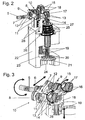
- FIG. 3 the individual directions of movement of the components of the coupling unit 10 are once again shown by arrows.
- the rotational movement of the drive shaft 5 is converted by the eccentrically arranged driver 6 substantially in a horizontal movement of the coupling element 8.
- this horizontal movement is substantially converted via the fixed rotating connecting shaft 14 in a rotational movement of the second eccentric 15.
- This transmits this movement to the bearings 17, resulting in a substantially vertical movement of the scenes 18 and thus the firmly connected to the scenes valve rods 19 is formed.
- this vertical movement will be two valve plates 20 which are fixedly connected to the valve rods 19, against their valve seats 21, which are part of a housing part 22, pressed.
- valve plates By the movement of the drive shaft 5 in the opposite direction, the valve plates are lifted from the valve seat 21, whereby a fluidic connection between the outlet port 23 and inlet port 24 is made.
- a spring element 25 is provided, which holds the valve rod 19 in the direction of the bearing 17 under tension.
- This bias is created by introducing the spring element 25 between a bearing surface 26 of the housing part 22 and a support ring 27, which is either part of the link 18, or as in the exemplary embodiment is arranged under the gate 18 spring plate.
- the support ring 27 of the link 18 is loaded in the direction of the roller bearing 17 by the force of the spring element 25 and thus the valve plate 20 is pressed via the valve stem 19 against the valve seat 21.
- the housing part 22 is constructed so that it not only includes the valve seat 21, the outlet opening 23, the inlet opening 24 and the support surface 26 for the spring element 25, but additionally has two bearing receiving socket 28 which receive the bearings 13 of the connecting shafts 14.
- the entire valve system is closed by a housing cover, not shown in the drawings.
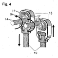
- the valves Due to the separation of the exhaust gas strands in the inlet region, the valves, depending on the position of the respective first eccentric 11 to the second eccentric 15 either synchronously, which is useful in particular in internal combustion engines in V-design, or as in FIG. 4 shown asynchronously operated.
- the second eccentric 15 of a coupling strand 9 is rotated by 180 ° compared to the eccentric 15 of the other coupling strand, whereby an opposite movement of the two valve rods 19 is formed.
- any angular position of the two eccentric 15 is conceivable to each other.
- a water cooling can be integrated into the housing, which makes it possible to install this valve when used as an exhaust gas recirculation valve and suction pipes made of plastic or magnesium.
- valves with an actuator are actuated independently by the use of the coupling unit.
- Such a design reduces costs, space and the number of components and thus weight.
- the valves are actively closed by the forced operation and also held in this closed position.
- Changes in the execution for example, a multi-part of the housing or other design of the valves, for example, as a cone valve or similar. do not limit the scope of the invention.
Landscapes
- Engineering & Computer Science (AREA)
- Mechanical Engineering (AREA)
- General Engineering & Computer Science (AREA)
- Chemical & Material Sciences (AREA)
- Combustion & Propulsion (AREA)
- Mechanically-Actuated Valves (AREA)
- Multiple-Way Valves (AREA)
Description
- Die Erfindung betrifft ein Abgasrückführventilsystem für Verbrennungskraftmaschinen zur Abgasrückführung mit einer Antriebswelle, einer exzentrisch angetriebenen Kupplungseinheit und zumindest zwei Ventilen, wobei jedes der Ventile zumindest aus einer Ventilstange, einem Ventilschließkörper und einem Ventilsitz besteht und wobei die Kupplungseinheit eine Wirkverbindung zwischen der Antriebseinheit und den mindestens zwei Ventilstangen derart herstellt, dass die rotatorische Bewegung der Antriebseinheit in eine lineare Bewegung der Ventilstangen umgewandelt wird.
- Das Prinzip eines solchen Ventilsystems wird beispielsweise in der
US 4,027,636 offenbart. Hier werden über eine Nockenwelle zwei Ventile betätigt, von denen eines ein Abgasrückführventil ist und eines im Lufteinlasskanal angeordnet ist und somit als Luftdrossel dient. Eine Entkoppelung zweier Abgasstränge sowie eine Regelung eines Abgastromes in zwei Abgassträngen mittels eines regelbaren Antriebs wird jedoch nicht offenbart. Nachteilig ist auch der benötigte große Bauraum. - In der Europäischen Patentanmeldung
EP 10 91 112 A2 und derEP 0 971 113 A2 werden AGR-Ventile beschrieben, welche im wesentlichen eine Antriebseinheit, eine Getriebeeinheit mit einem über einen Zapfen exzentrisch angeordneten Lager als Kupplungsteil und ein Ventil mit Ventilstange, Ventilschließglied und Ventilsitz aufweisen, wobei die Getriebeeinheit mit der Ventilstange in Wirkverbindung steht und dadurch das Ventil öffnen oder schließen kann. Des weiteren weist sie eine Auslaßöffnung und eine Einlaßöffnung auf. - Häufig ist es jedoch notwendig, die in einer Verbrennungskraftmaschine vorhandenen Abgasstränge voneinander zu entkoppeln. Dies ist beispielsweise bei Motoren in V-Bauform, bei denen das Abgas aus beiden Zylinderbänken zurückgeführt wird, der Fall. Dadurch wird es notwendig, für jeden Abgasstrang ein Ventil zur Abgasrückführung zu verwenden. Dabei wird jedes Ventil durch einen eigenen Antrieb betätigt. Dies führt zu einem hohen Kosten- und Montageaufwand. Zusätzlich muß jedes einzelne Ventil mit einer eigenen Sensorik zur Feststellung des Ventilhubes ausgestattet und mit der Auswerteeinheit verbunden werden.
- Hiervon ausgehend liegt der Erfindung die Aufgabe zugrunde, ein Ventilsystem zu schaffen, welches die oben genannten Nachteile vermeidet und zudem einfach aufgebaut und kostengünstig herzustellen ist.
- Diese Aufgabe wird durch den kennzeichnenden Teil des Hauptanspruchs gelöst.
- Vorteilhafterweise besteht die Kupplungseinheit aus einem durch die Antriebswelle exzentrisch angetriebenen Koppelelement und mindestens zwei fest mit dem Koppelelement verbundenen Kupplungssträngen, wobei die Kupplungsstränge jeweils aus einem ersten Exzenter, einer in einem Lager angeordneten Verbindungswelle, die an ihrem ersten Ende mit dem ersten Exzenter und an ihrem zweiten Ende mit einem zweiten Exzenter fest verbunden ist und einem fest mit dem zweiten Exzenter verbundenen Lagerelement bestehen.
- Ein derartig gestaltetes Ventilsystem benötigt somit zur Betätigung mehrerer Ventile nur noch eine Antriebseinheit und gegebenenfalls eine Sensoreinheit. Des weiteren wird für die Ventile nur noch ein Gehäuse benötigt, so daß das gesamte Ventilsystem fertig vormontiert am Ansaugstrang bzw. den Abgassträngen angebracht werden kann. Dies reduziert sowohl den mechanischen als auch den elektrischen Montageaufwand erheblich, wodurch zusätzlich zu den reduzierten Bauteilkosten auch eine Reduzierung der Montagekosten entsteht.
- Des weiteren ist es möglich, die Ventile je nach Winkelstellung des jeweils ersten zum jeweils zweiten Exzenter eines Kupplungsstranges entweder synchron, also gleichzeitiges Öffnen und Schließen der Ventile, insbesondere bei Verbrennungsmotoren in V-Bauform oder asynchron, also zeitlich versetztes Öffnen und Schließen der Ventile, zu betätigen. Dadurch wird eine Vielzahl von Einbaumöglichkeiten für ein solches Ventilsystem geschaffen.
- Dadurch, daß als Lagerelemente Wälz- oder Gleitlager eingesetzt werden, kann des weiteren eine besonders einfache und robuste Ausführungsform des Ventilsystems geschaffen werden.
- Eine besonders einfache Form der Lagerung der Verbindungswelle der beiden Exzenter wird dadurch geschaffen, daß das Lager mit dem Gehäuse des Ventilsystems verbunden ist. Die Wälzlager sind vorteilhafterweise in Kulissen angeordnet, die mit den Ventilstangen fest verbunden sind, so daß eine Zwangsführung der Ventilstangen entsteht.
- Bei einem Anbau dieses Ventilsystems an Saugrohre aus Kunststoff oder Magnesium kann eine Wasserkühlung in das Gehäuse integriert werden.
- Auf diese Art und Weise wird somit ein Ventilsystem geschaffen, welches einfach und robust aufgebaut ist und zusätzlich Gewicht spart. Des weiteren erreicht man eine hohe Flexibilität bezüglich Einbau und Vormontage. Durch die Zwangsführung können des weiteren die Ventile aktiv geschlossen und auch zugehalten werden.
- Ein Ausführungsbeispiel eines solchen Ventilsystems ist in den Zeichnungen dargestellt und wird nachfolgend beschrieben.
-
Figur 1 zeigt eine perspektivische Darstellung eines erfindungsgemäßen Ventilsystems mit geschnittenem Gehäuse und ohne Gehäusedeckel. -
Figur 2 zeigt eine perspektivische Darstellung des Ventilsystems ohne Antriebseinheit und ohne Gehäusedeckel mit geschnittenem Gehäuse. -
Figur 3 zeigt in perspektivischer Darstellung einen Ausschnitt des Ventilsystems ohne Gehäusedeckel und hier insbesondere eine erfindungsgemäße Kupplungseinheit und eine Kulisse zur Zwangsführung, mit Pfeilen zur Verdeutlichung der Bewegungsrichtung der einzelnen Bauteile der Kupplungseinrichtung. -
Figur 4 zeigt in perspektivischer Ansicht einen Abtriebsteil der Kupplungseinheit bei asynchronem Betrieb. - Das dargestellte Ventilsystem besteht aus einer Antriebseinheit 1, welche einen Elektromotor 2 mit einem Planetenstandgetriebe 3 und einer aus einem Motorgehäuse 4 austretenden Antriebswelle 5 besteht. Auf dem Ende der aus dem Motorgehäuse 4 austretenden Antriebswelle 5 ist ein exzentrisch angeordneter Mitnehmer 6 fest angebracht, der wiederum über einen Stift 7 mit einem Koppelelement 8, welches lotrecht zur Antriebswelle 5 steht, drehbar verbunden ist. Die Drehbewegung der Antriebswelle 5 wird über dieses Koppelelement auf zwei baugleiche Kupplungsstränge 9 übertragen. Der exzentrisch angeordnete Mitnehmer 6, der Stift 7, das Koppelelement 8 und die beiden Kupplungsstränge 9 bilden eine Kupplungseinheit 10. Jeder der beiden Kupplungsstränge 9 besteht aus einem ersten Exzenter 11, der wiederum über einen Stift 12 mit dem Koppelelement 8 verbunden ist, sowie einer in einem Lager 13, welches in Bezug auf die Antriebswelle 5 fest angebracht ist, angeordneten Verbindungswelle 14, die den ersten Exzenter 11 mit einem zweiten Exzenter 15 verbindet. Dieser zweite Exzenter 15 ist wiederum über einen Stift 16 mit einem Lagerelement, in diesem Fall einem Wälzlager 17 verbunden. Dieses Wälzlager 17 bildet gleichzeitig das Endglied der Kupplungseinheit 10 bzw. der beiden Kupplungsstränge 9. Die beiden Wälzlager 17 sind jeweils in einer Kulisse 18 angeordnet, die die Bewegung der Kupplungseinheit 10 bzw. des Wälzlagers 17 auf zwei Ventilstangen 19, die gleichzeitig durch die Kulisse 18 zwangsgeführt werden, überträgt.
- In
Figur 3 sind die einzelnen Bewegungsrichtungen der Bauelemente der Kupplungseinheit 10 noch einmal durch Pfeile dargestellt. Im einzelnen wird die Drehbewegung der Antriebswelle 5 durch den exzentrisch angeordneten Mitnehmer 6 im wesentlichen in eine horizontale Bewegung des Koppelelementes 8 umgewandelt. Über die beiden Exzenter 11 und 15 sowie die Verbindungswelle 14 wird diese horizontale Bewegung im wesentlichen über die feststehende rotierende Verbindungswelle 14 in eine rotatorische Bewegung des zweiten Exzenters 15 umgewandelt. Dieser wiederum überträgt diese Bewegung auf die Wälzlager 17, woraus eine im wesentlichen vertikale Bewegung der Kulissen 18 und somit der fest mit den Kulissen verbundenen Ventilstangen 19 entsteht. Durch diese vertikale Bewegung werden zwei Ventilteller 20, die fest mit den Ventilstangen 19 verbunden sind, gegen ihre Ventilsitze 21, die Teil eines Gehäuseteils 22 sind, gepreßt. Durch die Bewegung der Antriebswelle 5 in entgegengesetzte Richtung werden die Ventilteller vom Ventilsitz 21 abgehoben, wodurch eine fluidische Verbindung zwischen Auslaßöffnung 23 und Einlaßöffnung 24 hergestellt wird. Zur stromlosen Rückstellung des Ventiltellers 20 ist ein Federelement 25 vorgesehen, welches die Ventilstange 19 in Richtung des Lagers 17 unter Vorspannung hält. Diese Vorspannung entsteht durch Einbringen des Federelementes 25 zwischen einer Auflagefläche 26 des Gehäuseteils 22 und einem Auflagering 27, welcher entweder Teil der Kulisse 18 ist, oder wie im Ausführungsbeispiel ein unter der Kulisse 18 angeordneter Federteller ist. Bei einem Ausfall des Elektromotors 2 wird also der Auflagering 27 der Kulisse 18 in Richtung des Wälzlagers 17 durch die Kraft des Federelementes 25 belastet und somit der Ventilteller 20 über die Ventilstange 19 gegen den Ventilsitz 21 gepreßt. - Das Gehäuseteil 22 ist so aufgebaut, daß es nicht nur den Ventilsitz 21, die Auslaßöffnung 23, die Einlaßöffnung 24 sowie die Auflagefläche 26 für das Federelement 25 beinhaltet, sondern zusätzlich zwei Lageraufnahmesockel 28 aufweist, die die Lager 13 der Verbindungswellen 14 aufnehmen. Das gesamte Ventilsystem wird durch einen in den Zeichnungen nicht dargestellten Gehäusedeckel verschlossen.
- Durch die Trennung der Abgasstränge im Einlaßbereich können die Ventile je nach Stellung des jeweils ersten Exzenters 11 zum zweiten Exzenter 15 entweder synchron, was insbesondere bei Verbrennungsmotoren in V-Bauform sinnvoll ist, oder wie in
Figur 4 dargestellt asynchron betätigt werden. Hier ist der zweite Exzenter 15 eines Kupplungsstranges 9 um 180° im Vergleich zu dem Exzenter 15 des anderen Kupplungsstranges gedreht, wodurch eine entgegengesetzte Bewegung der beiden Ventilstangen 19 entsteht. Je nach Anwendung ist jedoch jede Winkelstellung der beiden Exzenter 15 zueinander vorstellbar. - Vorteilhafterweise kann in das Gehäuse eine Wasserkühlung integriert werden, was es möglich macht, dieses Ventil bei Einsatz als Abgasrückführventil auch an Saugrohren aus Kunststoff oder Magnesium anzubringen.
- Mit der erfindungsgemäßen Ausführung liegt eine Konstruktion vor, bei der durch Einsatz der Kupplungseinheit zwei oder mehrere Ventile mit einem Stellantrieb unabhängig voneinander betätigt werden. Eine solche Ausführung reduziert Kosten, Bauraum und die Anzahl der Bauteile und somit Gewicht. Des weiteren werden die Ventile durch die Zwangsführung aktiv geschlossen und auch in dieser Schließstellung gehalten.
- Veränderungen bezüglich der Ausführung, beispielsweise einer Mehrteiligkeit des Gehäuses oder einer anderen Ausführung der Ventile zum Beispiel als Kegelventil o.ä. beschränken den Schutzbereich der Erfindung nicht.
Claims (8)
- Abgasrückführventilsystem für Verbrennungskraftmaschinen zur Abgasrückführung mit einer Antriebswelle (5), einer exzentrisch angetriebenen Kupplungseinheit (10) und zumindest zwei Ventilen, wobei jedes der Ventile zumindest aus einer Ventilstange (19), einem Ventilschließkörper (20) und einem Ventilsitz (21) besteht und wobei die Kupplungseinheit (10) eine Wirkverbindung zwischen der Antriebseinheit (1) und den mindestens zwei Ventilstangen (19) derart herstellt, dass die rotatorische Bewegung der Antriebseinheit (1) in eine lineare Bewegung der Ventilstangen (19) umgewandelt wird, dadurch gekennzeichnet, daß die zumindest zwei Ventile, eine Antriebseinheit (1), die Antriebswelle (5) und die exzentrisch angetriebene Kupplungseinheit (10) in einem Gehäuse (4, 22) angeordnet sind, wobei die zumindest zwei Ventile in einer Ebene, die lotrecht zur Antriebswelle (5) der Antriebseinheit (1) verläuft, angeordnet sind und zumindest zwei Abgasstränge im Einlassbereich des Abgasrückführventilsystems trennen .
- Ventilsystem nach Anspruch 1, dadurch gekennzeichnet, daß die Kupplungseinheit (10) aus einem durch die Antriebswelle (5) exzentrisch angetriebenen Koppelelement (8) und mindestens zwei fest mit dem Koppelelement (8) verbundenen Kupplungssträngen (9) besteht, wobei die Kupplungsstränge (9) jeweils aus einem ersten Exzenter (11), einer in einem Lager (13) angeordneten Verbindungswelle (14), die an ihrem ersten Ende mit dem ersten Exzenter (11) und an ihrem zweiten Ende mit einem zweiten Exzenter (15) fest verbunden ist und einem fest mit dem zweiten Exzenter (15) verbundenen Lagerelement (17) bestehen.
- Ventilsystem nach Anspruch 1 oder 2, dadurch gekennzeichnet, daß die Ventile je nach Winkelstellung des jeweils ersten Exzenters (11) zum jeweils zweiten Exzenter (15) eines Kupplungsstranges (9) entweder synchron, insbesondere bei Verbrennungsmotoren in V-Bauform, oder asynchron betätigbar sind.
- Ventilsystem nach Anspruch 2, dadurch gekennzeichnet, daß die Lagerelemente Wälzlager (17) sind.
- Ventilsystem nach Anspruch 2, dadurch gekennzeichnet, daß die Lagerelemente Gleitlager sind.
- Ventilsystem nach Anspruch 2, 4 oder 5, dadurch gekennzeichnet, daß die Lagerelemente (13) der Verbindungswelle (14) fest mit dem Gehäuseteil (22) verbunden sind.
- Ventilsystem nach Anspruch 4 oder 5, dadurch gekennzeichnet, daß die Lager (17) in Kulissen (18) angeordnet sind, die mit den Ventilstangen (19) fest verbunden sind, so daß die Ventilstangen (19) zwangsgeführt sind.
- Ventilsystem nach einem der vorhergehenden Ansprüche, dadurch gekennzeichnet, daß eine Wasserkühlung im Gehäuseteil (22) angeordnet ist.
Applications Claiming Priority (2)
| Application Number | Priority Date | Filing Date | Title |
|---|---|---|---|
| DE10221711A DE10221711A1 (de) | 2002-05-16 | 2002-05-16 | Ventilsystem |
| DE10221711 | 2002-05-16 |
Publications (3)
| Publication Number | Publication Date |
|---|---|
| EP1362985A2 EP1362985A2 (de) | 2003-11-19 |
| EP1362985A3 EP1362985A3 (de) | 2007-08-29 |
| EP1362985B1 true EP1362985B1 (de) | 2009-11-25 |
Family
ID=29265314
Family Applications (1)
| Application Number | Title | Priority Date | Filing Date |
|---|---|---|---|
| EP03002950A Expired - Lifetime EP1362985B1 (de) | 2002-05-16 | 2003-02-11 | Ventilsystem |
Country Status (3)
| Country | Link |
|---|---|
| EP (1) | EP1362985B1 (de) |
| DE (2) | DE10221711A1 (de) |
| ES (1) | ES2335873T3 (de) |
Cited By (2)
| Publication number | Priority date | Publication date | Assignee | Title |
|---|---|---|---|---|
| CN103939170A (zh) * | 2014-03-07 | 2014-07-23 | 同济大学 | 一种用于二冲程自由活塞发动机-发电机系统的可控气门机构 |
| DE102014117309A1 (de) | 2014-11-26 | 2016-06-02 | Pierburg Gmbh | Ventilvorrichtung zur Abgasrückführung an einem Verbrennungsmotor |
Families Citing this family (15)
| Publication number | Priority date | Publication date | Assignee | Title |
|---|---|---|---|---|
| EP1793114B1 (de) * | 2005-12-02 | 2013-05-15 | Behr Thermot-tronik GmbH | Vorrichtung, insbesondere Abgasrückführventileinrichtung, zum Steuern oder Regeln eines Fluidstroms |
| DE102006053755A1 (de) * | 2005-12-02 | 2007-08-09 | Behr Thermot-Tronik Gmbh | Doppelventil für eine Einrichtung zur Abgasrückführung |
| DE102006023652B4 (de) * | 2006-05-18 | 2008-10-30 | Esa Patentverwertungsagentur Sachsen-Anhalt Gmbh | Elektromotorische Einrichtung zur Betätigung von Gaswechselventilen |
| DE102008005591A1 (de) * | 2008-01-22 | 2009-07-23 | Bayerische Motoren Werke Aktiengesellschaft | Ventileinrichtung für eine Abgasrückführungseinrichtung |
| DE102008027490A1 (de) | 2008-06-10 | 2009-12-31 | Pierburg Gmbh | Ventilsystem |
| DE102008030785B4 (de) | 2008-06-28 | 2012-10-31 | Pierburg Gmbh | Abgasrückführvorrichtung für eine Verbrennungskraftmaschine |
| DE102009036284A1 (de) | 2009-08-06 | 2011-02-24 | Pierburg Gmbh | Ventilvorrichtung für eine Verbrennungskraftmaschine |
| DE102009053428A1 (de) | 2009-11-19 | 2011-06-09 | Pierburg Gmbh | Stellvorrichtung zur Umwandlung einer rotatorischen Bewegung in eine lineare Bewegung |
| DE102009056251B4 (de) | 2009-12-01 | 2014-01-09 | Pierburg Gmbh | Ventilvorrichtung für eine Verbrennungskraftmaschine |
| DE102010006037B4 (de) | 2010-01-27 | 2013-01-17 | Pierburg Gmbh | Ventilvorrichtung für eine Verbrennungskraftmaschine |
| DE102010050784A1 (de) * | 2010-11-10 | 2012-05-10 | Pierburg Gmbh | Stellvorrichtung |
| FR2983252B1 (fr) | 2011-11-25 | 2015-01-30 | Valeo Systemes De Controle Moteur | Vanne de controle pour systeme de recirculation des gaz d'echappement d'un moteur a combustion interne |
| DE102013206481A1 (de) * | 2013-04-11 | 2014-10-16 | Mahle International Gmbh | Ventileinrichtung |
| DE102013215164A1 (de) * | 2013-08-01 | 2015-02-19 | Continental Automotive Gmbh | Einrichtung zur Steuerung eines in einem Ansaugkanal einer Brennkraftmaschine angeordneten Ladeluftkühlers und Verfahren zum Betrieb einer solchen Einrichtung |
| DE102015116872B4 (de) * | 2015-10-05 | 2019-11-28 | Pierburg Gmbh | Ventil für einen Verbrennungsmotor |
Family Cites Families (5)
| Publication number | Priority date | Publication date | Assignee | Title |
|---|---|---|---|---|
| JPS51138228A (en) * | 1975-05-26 | 1976-11-29 | Nissan Motor Co Ltd | Exhaust circulation device |
| US6012437A (en) * | 1998-07-06 | 2000-01-11 | Eaton Corporation | EGR system with improved control logic |
| ES2214998T3 (es) * | 1999-10-05 | 2004-10-01 | Pierburg Gmbh | Unidad de valvula, tramo de canal de aspiracion de aire de combustion, asi como unidad de reciclaje de gases de escape para motores de combustion interna. |
| DE19948379B4 (de) * | 1999-10-07 | 2009-11-05 | Linde Material Handling Gmbh | Hydraulisches Steuerventil |
| JP3597453B2 (ja) * | 2000-09-22 | 2004-12-08 | 株式会社市丸技研 | 直動形電動バルブ |
-
2002
- 2002-05-16 DE DE10221711A patent/DE10221711A1/de not_active Withdrawn
-
2003
- 2003-02-11 ES ES03002950T patent/ES2335873T3/es not_active Expired - Lifetime
- 2003-02-11 DE DE50312149T patent/DE50312149D1/de not_active Expired - Lifetime
- 2003-02-11 EP EP03002950A patent/EP1362985B1/de not_active Expired - Lifetime
Cited By (3)
| Publication number | Priority date | Publication date | Assignee | Title |
|---|---|---|---|---|
| CN103939170A (zh) * | 2014-03-07 | 2014-07-23 | 同济大学 | 一种用于二冲程自由活塞发动机-发电机系统的可控气门机构 |
| DE102014117309A1 (de) | 2014-11-26 | 2016-06-02 | Pierburg Gmbh | Ventilvorrichtung zur Abgasrückführung an einem Verbrennungsmotor |
| DE102014117309B4 (de) * | 2014-11-26 | 2021-02-04 | Pierburg Gmbh | Ventilvorrichtung zur Abgasrückführung an einem Verbrennungsmotor |
Also Published As
| Publication number | Publication date |
|---|---|
| EP1362985A3 (de) | 2007-08-29 |
| DE10221711A1 (de) | 2003-11-27 |
| ES2335873T3 (es) | 2010-04-06 |
| EP1362985A2 (de) | 2003-11-19 |
| DE50312149D1 (de) | 2010-01-07 |
Similar Documents
| Publication | Publication Date | Title |
|---|---|---|
| EP1362985A2 (de) | Ventilsystem | |
| EP0725210B1 (de) | Saugmodul | |
| DE102015111742B4 (de) | Vorrichtung zur Steuerung von Ansaugluft eines Motors | |
| EP1091112B1 (de) | Ventileinheit, Brennluftansaugkanalabschnitt sowie Abgasrückführeinheit für Brennkraftmaschinen | |
| DE102017222465B4 (de) | Klappeneinrichtung für den Abgasstrang eines Verbrennungsmotors | |
| DE102005051937A1 (de) | Schubumluftventilvorrichtung für eine Brennkraftmaschine | |
| EP3615787B1 (de) | Regelvorrichtung für eine verbrennungskraftmaschine | |
| EP1457645A1 (de) | Ventiltrieb für einen Verbrennungsmotor | |
| DE102018112815A1 (de) | Variabler Ventiltrieb einer Hubkolbenbrennkraftmaschine | |
| DE102010006037B4 (de) | Ventilvorrichtung für eine Verbrennungskraftmaschine | |
| CH638870A5 (de) | Startventilvorrichtung, insbesondere fuer dieselmotoren mit druckwellenlader. | |
| DE102017130323B3 (de) | Ventilvorrichtung für eine Verbrennungskraftmaschine | |
| DE102009039911A1 (de) | Umströmungseinrichtung für eine Aufladevorrichtung | |
| DE102004009502B3 (de) | Klappensystem, insbesondere zur Änderung der Strömungsverhältnisse an Einlassventilen | |
| DE102009043627A1 (de) | Ansaugeinrichtung für Verbrennungsmotoren | |
| DE60125829T2 (de) | Luftklappenlageranordnung | |
| DE102006028488B4 (de) | Verstellstange | |
| DE102016112403B4 (de) | Regelvorrichtung für eine Verbrennungskraftmaschine und Verfahren zum Betreiben einer solchen | |
| WO2012110212A1 (de) | Betätigungseinrichtung für einen abgasturbolader | |
| EP2133549A2 (de) | Ventilsystem | |
| DE102008022468B4 (de) | Ladeeinrichtung | |
| DE10254102B4 (de) | Stellantriebsvorrichtung | |
| EP3070318A1 (de) | Hebelanordnung | |
| EP2993381B1 (de) | Ventilvorrichtung für eine verbrennungskraftmaschine | |
| EP2574831A1 (de) | Stellvorrichtung |
Legal Events
| Date | Code | Title | Description |
|---|---|---|---|
| PUAI | Public reference made under article 153(3) epc to a published international application that has entered the european phase |
Free format text: ORIGINAL CODE: 0009012 |
|
| 17P | Request for examination filed |
Effective date: 20030211 |
|
| AK | Designated contracting states |
Kind code of ref document: A2 Designated state(s): AT BE BG CH CY CZ DE DK EE ES FI FR GB GR HU IE IT LI LU MC NL PT SE SI SK TR |
|
| AX | Request for extension of the european patent |
Extension state: AL LT LV MK RO |
|
| PUAL | Search report despatched |
Free format text: ORIGINAL CODE: 0009013 |
|
| AK | Designated contracting states |
Kind code of ref document: A3 Designated state(s): AT BE BG CH CY CZ DE DK EE ES FI FR GB GR HU IE IT LI LU MC NL PT SE SI SK TR |
|
| AX | Request for extension of the european patent |
Extension state: AL LT LV MK RO |
|
| 17Q | First examination report despatched |
Effective date: 20071123 |
|
| AKX | Designation fees paid |
Designated state(s): DE ES FR GB IT |
|
| GRAP | Despatch of communication of intention to grant a patent |
Free format text: ORIGINAL CODE: EPIDOSNIGR1 |
|
| GRAS | Grant fee paid |
Free format text: ORIGINAL CODE: EPIDOSNIGR3 |
|
| GRAA | (expected) grant |
Free format text: ORIGINAL CODE: 0009210 |
|
| AK | Designated contracting states |
Kind code of ref document: B1 Designated state(s): DE ES FR GB IT |
|
| REG | Reference to a national code |
Ref country code: GB Ref legal event code: FG4D Free format text: NOT ENGLISH |
|
| REF | Corresponds to: |
Ref document number: 50312149 Country of ref document: DE Date of ref document: 20100107 Kind code of ref document: P |
|
| REG | Reference to a national code |
Ref country code: ES Ref legal event code: FG2A Ref document number: 2335873 Country of ref document: ES Kind code of ref document: T3 |
|
| PGFP | Annual fee paid to national office [announced via postgrant information from national office to epo] |
Ref country code: ES Payment date: 20100219 Year of fee payment: 8 |
|
| PGFP | Annual fee paid to national office [announced via postgrant information from national office to epo] |
Ref country code: FR Payment date: 20100315 Year of fee payment: 8 Ref country code: IT Payment date: 20100226 Year of fee payment: 8 |
|
| PGFP | Annual fee paid to national office [announced via postgrant information from national office to epo] |
Ref country code: GB Payment date: 20100219 Year of fee payment: 8 |
|
| PLBE | No opposition filed within time limit |
Free format text: ORIGINAL CODE: 0009261 |
|
| STAA | Information on the status of an ep patent application or granted ep patent |
Free format text: STATUS: NO OPPOSITION FILED WITHIN TIME LIMIT |
|
| 26N | No opposition filed |
Effective date: 20100826 |
|
| GBPC | Gb: european patent ceased through non-payment of renewal fee |
Effective date: 20110211 |
|
| REG | Reference to a national code |
Ref country code: FR Ref legal event code: ST Effective date: 20111102 |
|
| PG25 | Lapsed in a contracting state [announced via postgrant information from national office to epo] |
Ref country code: IT Free format text: LAPSE BECAUSE OF NON-PAYMENT OF DUE FEES Effective date: 20110211 |
|
| PG25 | Lapsed in a contracting state [announced via postgrant information from national office to epo] |
Ref country code: FR Free format text: LAPSE BECAUSE OF NON-PAYMENT OF DUE FEES Effective date: 20110228 |
|
| PG25 | Lapsed in a contracting state [announced via postgrant information from national office to epo] |
Ref country code: GB Free format text: LAPSE BECAUSE OF NON-PAYMENT OF DUE FEES Effective date: 20110211 |
|
| REG | Reference to a national code |
Ref country code: ES Ref legal event code: FD2A Effective date: 20120411 |
|
| PG25 | Lapsed in a contracting state [announced via postgrant information from national office to epo] |
Ref country code: ES Free format text: LAPSE BECAUSE OF NON-PAYMENT OF DUE FEES Effective date: 20110212 |
|
| PGFP | Annual fee paid to national office [announced via postgrant information from national office to epo] |
Ref country code: DE Payment date: 20220217 Year of fee payment: 20 |
|
| REG | Reference to a national code |
Ref country code: DE Ref legal event code: R071 Ref document number: 50312149 Country of ref document: DE |