EP1362985B1 - Système de soupapes - Google Patents
Système de soupapes Download PDFInfo
- Publication number
- EP1362985B1 EP1362985B1 EP03002950A EP03002950A EP1362985B1 EP 1362985 B1 EP1362985 B1 EP 1362985B1 EP 03002950 A EP03002950 A EP 03002950A EP 03002950 A EP03002950 A EP 03002950A EP 1362985 B1 EP1362985 B1 EP 1362985B1
- Authority
- EP
- European Patent Office
- Prior art keywords
- valve
- valve system
- coupling
- eccentric
- valves
- Prior art date
- Legal status (The legal status is an assumption and is not a legal conclusion. Google has not performed a legal analysis and makes no representation as to the accuracy of the status listed.)
- Expired - Lifetime
Links
- 230000008878 coupling Effects 0.000 claims description 34
- 238000010168 coupling process Methods 0.000 claims description 34
- 238000005859 coupling reaction Methods 0.000 claims description 34
- 238000002485 combustion reaction Methods 0.000 claims description 6
- 238000001816 cooling Methods 0.000 claims description 3
- XLYOFNOQVPJJNP-UHFFFAOYSA-N water Substances O XLYOFNOQVPJJNP-UHFFFAOYSA-N 0.000 claims description 3
- 238000005096 rolling process Methods 0.000 description 4
- FYYHWMGAXLPEAU-UHFFFAOYSA-N Magnesium Chemical compound [Mg] FYYHWMGAXLPEAU-UHFFFAOYSA-N 0.000 description 2
- 238000009434 installation Methods 0.000 description 2
- 229910052749 magnesium Inorganic materials 0.000 description 2
- 239000011777 magnesium Substances 0.000 description 2
- 239000004033 plastic Substances 0.000 description 2
- 238000010276 construction Methods 0.000 description 1
- 238000010616 electrical installation Methods 0.000 description 1
- 238000011156 evaluation Methods 0.000 description 1
- 238000004519 manufacturing process Methods 0.000 description 1
- 238000000926 separation method Methods 0.000 description 1
Images

Classifications
-
- F—MECHANICAL ENGINEERING; LIGHTING; HEATING; WEAPONS; BLASTING
- F01—MACHINES OR ENGINES IN GENERAL; ENGINE PLANTS IN GENERAL; STEAM ENGINES
- F01L—CYCLICALLY OPERATING VALVES FOR MACHINES OR ENGINES
- F01L1/00—Valve-gear or valve arrangements, e.g. lift-valve gear
- F01L1/12—Transmitting gear between valve drive and valve
-
- F—MECHANICAL ENGINEERING; LIGHTING; HEATING; WEAPONS; BLASTING
- F01—MACHINES OR ENGINES IN GENERAL; ENGINE PLANTS IN GENERAL; STEAM ENGINES
- F01L—CYCLICALLY OPERATING VALVES FOR MACHINES OR ENGINES
- F01L1/00—Valve-gear or valve arrangements, e.g. lift-valve gear
- F01L1/02—Valve drive
- F01L1/04—Valve drive by means of cams, camshafts, cam discs, eccentrics or the like
- F01L1/047—Camshafts
- F01L1/053—Camshafts overhead type
-
- F—MECHANICAL ENGINEERING; LIGHTING; HEATING; WEAPONS; BLASTING
- F01—MACHINES OR ENGINES IN GENERAL; ENGINE PLANTS IN GENERAL; STEAM ENGINES
- F01L—CYCLICALLY OPERATING VALVES FOR MACHINES OR ENGINES
- F01L1/00—Valve-gear or valve arrangements, e.g. lift-valve gear
- F01L1/26—Valve-gear or valve arrangements, e.g. lift-valve gear characterised by the provision of two or more valves operated simultaneously by same transmitting-gear; peculiar to machines or engines with more than two lift-valves per cylinder
-
- F—MECHANICAL ENGINEERING; LIGHTING; HEATING; WEAPONS; BLASTING
- F01—MACHINES OR ENGINES IN GENERAL; ENGINE PLANTS IN GENERAL; STEAM ENGINES
- F01L—CYCLICALLY OPERATING VALVES FOR MACHINES OR ENGINES
- F01L1/00—Valve-gear or valve arrangements, e.g. lift-valve gear
- F01L1/34—Valve-gear or valve arrangements, e.g. lift-valve gear characterised by the provision of means for changing the timing of the valves without changing the duration of opening and without affecting the magnitude of the valve lift
- F01L1/344—Valve-gear or valve arrangements, e.g. lift-valve gear characterised by the provision of means for changing the timing of the valves without changing the duration of opening and without affecting the magnitude of the valve lift changing the angular relationship between crankshaft and camshaft, e.g. using helicoidal gear
- F01L1/352—Valve-gear or valve arrangements, e.g. lift-valve gear characterised by the provision of means for changing the timing of the valves without changing the duration of opening and without affecting the magnitude of the valve lift changing the angular relationship between crankshaft and camshaft, e.g. using helicoidal gear using bevel or epicyclic gear
-
- F—MECHANICAL ENGINEERING; LIGHTING; HEATING; WEAPONS; BLASTING
- F01—MACHINES OR ENGINES IN GENERAL; ENGINE PLANTS IN GENERAL; STEAM ENGINES
- F01L—CYCLICALLY OPERATING VALVES FOR MACHINES OR ENGINES
- F01L3/00—Lift-valve, i.e. cut-off apparatus with closure members having at least a component of their opening and closing motion perpendicular to the closing faces; Parts or accessories thereof
- F01L3/10—Connecting springs to valve members
-
- F—MECHANICAL ENGINEERING; LIGHTING; HEATING; WEAPONS; BLASTING
- F01—MACHINES OR ENGINES IN GENERAL; ENGINE PLANTS IN GENERAL; STEAM ENGINES
- F01L—CYCLICALLY OPERATING VALVES FOR MACHINES OR ENGINES
- F01L9/00—Valve-gear or valve arrangements actuated non-mechanically
- F01L9/20—Valve-gear or valve arrangements actuated non-mechanically by electric means
-
- F—MECHANICAL ENGINEERING; LIGHTING; HEATING; WEAPONS; BLASTING
- F01—MACHINES OR ENGINES IN GENERAL; ENGINE PLANTS IN GENERAL; STEAM ENGINES
- F01L—CYCLICALLY OPERATING VALVES FOR MACHINES OR ENGINES
- F01L9/00—Valve-gear or valve arrangements actuated non-mechanically
- F01L9/20—Valve-gear or valve arrangements actuated non-mechanically by electric means
- F01L9/22—Valve-gear or valve arrangements actuated non-mechanically by electric means actuated by rotary motors
-
- F—MECHANICAL ENGINEERING; LIGHTING; HEATING; WEAPONS; BLASTING
- F02—COMBUSTION ENGINES; HOT-GAS OR COMBUSTION-PRODUCT ENGINE PLANTS
- F02M—SUPPLYING COMBUSTION ENGINES IN GENERAL WITH COMBUSTIBLE MIXTURES OR CONSTITUENTS THEREOF
- F02M26/00—Engine-pertinent apparatus for adding exhaust gases to combustion-air, main fuel or fuel-air mixture, e.g. by exhaust gas recirculation [EGR] systems
- F02M26/13—Arrangement or layout of EGR passages, e.g. in relation to specific engine parts or for incorporation of accessories
- F02M26/38—Arrangement or layout of EGR passages, e.g. in relation to specific engine parts or for incorporation of accessories with two or more EGR valves disposed in parallel
-
- F—MECHANICAL ENGINEERING; LIGHTING; HEATING; WEAPONS; BLASTING
- F02—COMBUSTION ENGINES; HOT-GAS OR COMBUSTION-PRODUCT ENGINE PLANTS
- F02M—SUPPLYING COMBUSTION ENGINES IN GENERAL WITH COMBUSTIBLE MIXTURES OR CONSTITUENTS THEREOF
- F02M26/00—Engine-pertinent apparatus for adding exhaust gases to combustion-air, main fuel or fuel-air mixture, e.g. by exhaust gas recirculation [EGR] systems
- F02M26/52—Systems for actuating EGR valves
- F02M26/53—Systems for actuating EGR valves using electric actuators, e.g. solenoids
- F02M26/54—Rotary actuators, e.g. step motors
-
- F—MECHANICAL ENGINEERING; LIGHTING; HEATING; WEAPONS; BLASTING
- F02—COMBUSTION ENGINES; HOT-GAS OR COMBUSTION-PRODUCT ENGINE PLANTS
- F02M—SUPPLYING COMBUSTION ENGINES IN GENERAL WITH COMBUSTIBLE MIXTURES OR CONSTITUENTS THEREOF
- F02M26/00—Engine-pertinent apparatus for adding exhaust gases to combustion-air, main fuel or fuel-air mixture, e.g. by exhaust gas recirculation [EGR] systems
- F02M26/65—Constructional details of EGR valves
- F02M26/66—Lift valves, e.g. poppet valves
- F02M26/67—Pintles; Spindles; Springs; Bearings; Sealings; Connections to actuators
-
- F—MECHANICAL ENGINEERING; LIGHTING; HEATING; WEAPONS; BLASTING
- F02—COMBUSTION ENGINES; HOT-GAS OR COMBUSTION-PRODUCT ENGINE PLANTS
- F02M—SUPPLYING COMBUSTION ENGINES IN GENERAL WITH COMBUSTIBLE MIXTURES OR CONSTITUENTS THEREOF
- F02M26/00—Engine-pertinent apparatus for adding exhaust gases to combustion-air, main fuel or fuel-air mixture, e.g. by exhaust gas recirculation [EGR] systems
- F02M26/65—Constructional details of EGR valves
- F02M26/66—Lift valves, e.g. poppet valves
- F02M26/69—Lift valves, e.g. poppet valves having two or more valve-closing members
-
- F—MECHANICAL ENGINEERING; LIGHTING; HEATING; WEAPONS; BLASTING
- F01—MACHINES OR ENGINES IN GENERAL; ENGINE PLANTS IN GENERAL; STEAM ENGINES
- F01L—CYCLICALLY OPERATING VALVES FOR MACHINES OR ENGINES
- F01L1/00—Valve-gear or valve arrangements, e.g. lift-valve gear
- F01L1/30—Valve-gear or valve arrangements, e.g. lift-valve gear characterised by the provision of positively opened and closed valves, i.e. desmodromic valves
-
- F—MECHANICAL ENGINEERING; LIGHTING; HEATING; WEAPONS; BLASTING
- F01—MACHINES OR ENGINES IN GENERAL; ENGINE PLANTS IN GENERAL; STEAM ENGINES
- F01L—CYCLICALLY OPERATING VALVES FOR MACHINES OR ENGINES
- F01L2301/00—Using particular materials
-
- F—MECHANICAL ENGINEERING; LIGHTING; HEATING; WEAPONS; BLASTING
- F01—MACHINES OR ENGINES IN GENERAL; ENGINE PLANTS IN GENERAL; STEAM ENGINES
- F01L—CYCLICALLY OPERATING VALVES FOR MACHINES OR ENGINES
- F01L2305/00—Valve arrangements comprising rollers
-
- F—MECHANICAL ENGINEERING; LIGHTING; HEATING; WEAPONS; BLASTING
- F01—MACHINES OR ENGINES IN GENERAL; ENGINE PLANTS IN GENERAL; STEAM ENGINES
- F01L—CYCLICALLY OPERATING VALVES FOR MACHINES OR ENGINES
- F01L2800/00—Methods of operation using a variable valve timing mechanism
- F01L2800/10—Providing exhaust gas recirculation [EGR]
-
- F—MECHANICAL ENGINEERING; LIGHTING; HEATING; WEAPONS; BLASTING
- F02—COMBUSTION ENGINES; HOT-GAS OR COMBUSTION-PRODUCT ENGINE PLANTS
- F02M—SUPPLYING COMBUSTION ENGINES IN GENERAL WITH COMBUSTIBLE MIXTURES OR CONSTITUENTS THEREOF
- F02M26/00—Engine-pertinent apparatus for adding exhaust gases to combustion-air, main fuel or fuel-air mixture, e.g. by exhaust gas recirculation [EGR] systems
- F02M26/13—Arrangement or layout of EGR passages, e.g. in relation to specific engine parts or for incorporation of accessories
- F02M26/42—Arrangement or layout of EGR passages, e.g. in relation to specific engine parts or for incorporation of accessories having two or more EGR passages; EGR systems specially adapted for engines having two or more cylinders
-
- F—MECHANICAL ENGINEERING; LIGHTING; HEATING; WEAPONS; BLASTING
- F02—COMBUSTION ENGINES; HOT-GAS OR COMBUSTION-PRODUCT ENGINE PLANTS
- F02M—SUPPLYING COMBUSTION ENGINES IN GENERAL WITH COMBUSTIBLE MIXTURES OR CONSTITUENTS THEREOF
- F02M26/00—Engine-pertinent apparatus for adding exhaust gases to combustion-air, main fuel or fuel-air mixture, e.g. by exhaust gas recirculation [EGR] systems
- F02M26/65—Constructional details of EGR valves
- F02M26/72—Housings
- F02M26/73—Housings with means for heating or cooling the EGR valve
Definitions
- the invention relates to an exhaust gas recirculation valve system for internal combustion engines for exhaust gas recirculation with a drive shaft, an eccentrically driven clutch unit and at least two valves, wherein each of the valves at least a valve rod, a valve closing body and a valve seat and wherein the coupling unit is an operative connection between the drive unit and the at least two Valve rods manufactured in such a way that the rotational movement of the drive unit is converted into a linear movement of the valve rods.
- valve system for example, in the US 4,027,636 disclosed.
- two valves are actuated via a camshaft, one of which is an exhaust gas recirculation valve and one is arranged in the air inlet duct and thus serves as an air throttle.
- a decoupling of two exhaust gas lines and a regulation of an exhaust gas flow in two exhaust gas lines by means of a controllable drive is not disclosed.
- Another disadvantage is the required large space.
- EGR valves which essentially have a drive unit, a gear unit with a pin eccentrically arranged bearing as a coupling part and a valve with valve rod, valve closing member and valve seat, wherein the gear unit is in operative connection with the valve rod and thereby open the valve or can close. Furthermore, it has an outlet opening and an inlet opening.
- the present invention seeks to provide a valve system which avoids the disadvantages mentioned above and also simple and inexpensive to manufacture.
- the coupling unit consists of a coupling element driven eccentrically by the drive shaft and at least two coupling strands fixedly connected to the coupling element, the coupling strands each consisting of a first eccentric, a connecting shaft arranged in a bearing, which at its first end with the first eccentric and at its second end is fixedly connected to a second eccentric and a fixedly connected to the second eccentric bearing element.
- Such a designed valve system thus requires only a drive unit and optionally a sensor unit for actuating a plurality of valves. Furthermore, only one housing is required for the valves so that the entire valve system can be pre-assembled on the intake line or the exhaust gas lines. This considerably reduces both the mechanical and the electrical installation effort, which in addition to the reduced component costs also results in a reduction of the assembly costs.
- valves either synchronously, ie simultaneous opening and closing of the valves, especially in internal combustion engines in V-design or asynchronous, ie temporally offset opening and closing valves, to operate. This creates a variety of installation options for such a valve system.
- a particularly simple form of storage of the connecting shaft of the two eccentrics is created by the fact that the bearing is connected to the housing of the valve system.
- the bearings are advantageously arranged in scenes, which are firmly connected to the valve rods, so that a positive guidance of the valve rods is formed.
- valve system is thus created, which is simple and robust and also saves weight. Furthermore, one achieves a high degree of flexibility with regard to installation and pre-assembly. Due to the forced operation, the valves can also be actively closed and locked.
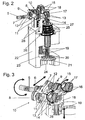
- the illustrated valve system consists of a drive unit 1, which consists of an electric motor 2 with a planetary gear 3 and a drive shaft 5 emerging from a motor housing 4.
- a drive unit 1 which consists of an electric motor 2 with a planetary gear 3 and a drive shaft 5 emerging from a motor housing 4.
- an eccentrically arranged driver 6 is fixedly mounted, which in turn is rotatably connected via a pin 7 with a coupling element 8, which is perpendicular to the drive shaft 5.
- the rotational movement of the drive shaft 5 is transmitted via this coupling element to two identical coupling strands 9.
- the eccentrically arranged driver 6, the pin 7, the coupling element 8 and the two coupling strands 9 form a coupling unit 10.
- Each of the two coupling strands 9 consists of a first eccentric 11, which in turn is connected via a pin 12 to the coupling element 8, and a in a bearing 13, which is fixedly mounted with respect to the drive shaft 5, arranged connecting shaft 14, which connects the first eccentric 11 with a second eccentric 15.
- This second eccentric 15 is in turn connected via a pin 16 to a bearing element, in this case a rolling bearing 17.
- the two rolling bearings 17 are each arranged in a slot 18, the movement of the coupling unit 10 and the rolling bearing 17 on two valve rods 19, which at the same time through the backdrop 18 be forced, transfers.
- FIG. 3 the individual directions of movement of the components of the coupling unit 10 are once again shown by arrows.
- the rotational movement of the drive shaft 5 is converted by the eccentrically arranged driver 6 substantially in a horizontal movement of the coupling element 8.
- this horizontal movement is substantially converted via the fixed rotating connecting shaft 14 in a rotational movement of the second eccentric 15.
- This transmits this movement to the bearings 17, resulting in a substantially vertical movement of the scenes 18 and thus the firmly connected to the scenes valve rods 19 is formed.
- this vertical movement will be two valve plates 20 which are fixedly connected to the valve rods 19, against their valve seats 21, which are part of a housing part 22, pressed.
- valve plates By the movement of the drive shaft 5 in the opposite direction, the valve plates are lifted from the valve seat 21, whereby a fluidic connection between the outlet port 23 and inlet port 24 is made.
- a spring element 25 is provided, which holds the valve rod 19 in the direction of the bearing 17 under tension.
- This bias is created by introducing the spring element 25 between a bearing surface 26 of the housing part 22 and a support ring 27, which is either part of the link 18, or as in the exemplary embodiment is arranged under the gate 18 spring plate.
- the support ring 27 of the link 18 is loaded in the direction of the roller bearing 17 by the force of the spring element 25 and thus the valve plate 20 is pressed via the valve stem 19 against the valve seat 21.
- the housing part 22 is constructed so that it not only includes the valve seat 21, the outlet opening 23, the inlet opening 24 and the support surface 26 for the spring element 25, but additionally has two bearing receiving socket 28 which receive the bearings 13 of the connecting shafts 14.
- the entire valve system is closed by a housing cover, not shown in the drawings.
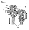
- the valves Due to the separation of the exhaust gas strands in the inlet region, the valves, depending on the position of the respective first eccentric 11 to the second eccentric 15 either synchronously, which is useful in particular in internal combustion engines in V-design, or as in FIG. 4 shown asynchronously operated.
- the second eccentric 15 of a coupling strand 9 is rotated by 180 ° compared to the eccentric 15 of the other coupling strand, whereby an opposite movement of the two valve rods 19 is formed.
- any angular position of the two eccentric 15 is conceivable to each other.
- a water cooling can be integrated into the housing, which makes it possible to install this valve when used as an exhaust gas recirculation valve and suction pipes made of plastic or magnesium.
- valves with an actuator are actuated independently by the use of the coupling unit.
- Such a design reduces costs, space and the number of components and thus weight.
- the valves are actively closed by the forced operation and also held in this closed position.
- Changes in the execution for example, a multi-part of the housing or other design of the valves, for example, as a cone valve or similar. do not limit the scope of the invention.
Landscapes
- Engineering & Computer Science (AREA)
- Mechanical Engineering (AREA)
- General Engineering & Computer Science (AREA)
- Chemical & Material Sciences (AREA)
- Combustion & Propulsion (AREA)
- Mechanically-Actuated Valves (AREA)
- Multiple-Way Valves (AREA)
Claims (8)
- Système de vannes à récirculation de gaz d'échappement pour moteurs à combustion interne pour la récirculation de gaz d'échappement, comprenant un arbre d'entraînement (5), une unité d'accouplement (10) entraînée de manière excentrique, et au moins deux vannes, chaque vanne étant composée au moins d'une tige de vanne (19), un corps de fermeture de vanne (20) et un siège de vanne (21), et l'unité d'accouplement (10) formant une liaison active entre l'unité d'entraînement (1) et les au moins deux tiges de vanne (19) de sorte que le mouvement en rotation de ladite unité d'entraînement (1) est traduit en un mouvement linéaire des tiges de vanne (19), caractérisé en ce que lesdites au moins deux vannes, ladite une unité d'entraînement (1), l'arbre d'entraînement (5) et l'unité d'accouplement (10) entraînée de manière excentrique sont disposés dans un carter (4, 22), lesdites au moins deux vannes étant arrangées dans un plan perpendiculaire à l'arbre d'entraînement (5) de ladite unité d'entraînement (1) et séparant au moins deux chaînes de gaz d'échappement dans la région d'entrée du système de vannes à récirculation de gaz d'échappement.
- Système de vannes selon la revendication 1, caractérisé en ce que l'unité d'accouplement (10) est composée d'un élément de couplage (8) entraîné de manière excentrique par ledit arbre d'entraînement (5) et d'au moins deux chaînes d'accouplement (9) rigidement raccordées audit élément de couplage (8), chacune desdites chaînes d'accouplement (9) étant formée par un premier excentrique (11), un arbre de liaison (14) disposé dans un palier (13), dont la première extrémité est rigidement raccordée au premier excentrique (11) et la deuxième extrémité est rigidement fixée à un deuxième excentrique (15), et un élément de palier (17) rigidement fixé audit deuxième excentrique (15).
- Système de vannes selon la revendication 1 ou 2, caractérisé en ce que les vannes sont opérables de manière synchrone, notamment pour des moteurs à combustion en V, ou asynchrone, en fonction de la position angulaire dudit premier excentrique (11) respectif par rapport audit deuxième excentrique (15) respectif d'une chaîne d'accouplement (9).
- Système de vannes selon la revendication 2, caractérisé en ce que les éléments de palier sont des paliers à rouleau (17).
- Système de vannes selon la revendication 2, caractérisé en ce que les éléments de palier son des paliers lisses.
- Système de vannes selon la revendication 2, 4 ou 5, caractérisé en ce que les éléments de palier (13) de l'arbre de liaison (14) sont rigidement fixés à l'élément carter (22).
- Système de vannes selon la revendication 4 ou 5, caractérisé en ce que les paliers (17) sont disposés dans des coulisses (18) rigidement fixées auxdites tiges de vanne (19) de sorte que lesdites tiges de vanne (19) sont guidées par guidage forcé.
- Système de vannes selon l'une des revendications précédentes, caractérisé en ce qu'une refroidissement par eau est prévue dans l'élément carter (22).
Applications Claiming Priority (2)
| Application Number | Priority Date | Filing Date | Title |
|---|---|---|---|
| DE10221711A DE10221711A1 (de) | 2002-05-16 | 2002-05-16 | Ventilsystem |
| DE10221711 | 2002-05-16 |
Publications (3)
| Publication Number | Publication Date |
|---|---|
| EP1362985A2 EP1362985A2 (fr) | 2003-11-19 |
| EP1362985A3 EP1362985A3 (fr) | 2007-08-29 |
| EP1362985B1 true EP1362985B1 (fr) | 2009-11-25 |
Family
ID=29265314
Family Applications (1)
| Application Number | Title | Priority Date | Filing Date |
|---|---|---|---|
| EP03002950A Expired - Lifetime EP1362985B1 (fr) | 2002-05-16 | 2003-02-11 | Système de soupapes |
Country Status (3)
| Country | Link |
|---|---|
| EP (1) | EP1362985B1 (fr) |
| DE (2) | DE10221711A1 (fr) |
| ES (1) | ES2335873T3 (fr) |
Cited By (2)
| Publication number | Priority date | Publication date | Assignee | Title |
|---|---|---|---|---|
| CN103939170A (zh) * | 2014-03-07 | 2014-07-23 | 同济大学 | 一种用于二冲程自由活塞发动机-发电机系统的可控气门机构 |
| DE102014117309A1 (de) | 2014-11-26 | 2016-06-02 | Pierburg Gmbh | Ventilvorrichtung zur Abgasrückführung an einem Verbrennungsmotor |
Families Citing this family (15)
| Publication number | Priority date | Publication date | Assignee | Title |
|---|---|---|---|---|
| EP1793114B1 (fr) * | 2005-12-02 | 2013-05-15 | Behr Thermot-tronik GmbH | Appareil, en particulier vanne de recyclage des gaz d'échappement, pour commander un courant de fluide |
| DE102006053755A1 (de) * | 2005-12-02 | 2007-08-09 | Behr Thermot-Tronik Gmbh | Doppelventil für eine Einrichtung zur Abgasrückführung |
| DE102006023652B4 (de) * | 2006-05-18 | 2008-10-30 | Esa Patentverwertungsagentur Sachsen-Anhalt Gmbh | Elektromotorische Einrichtung zur Betätigung von Gaswechselventilen |
| DE102008005591A1 (de) * | 2008-01-22 | 2009-07-23 | Bayerische Motoren Werke Aktiengesellschaft | Ventileinrichtung für eine Abgasrückführungseinrichtung |
| DE102008027490A1 (de) | 2008-06-10 | 2009-12-31 | Pierburg Gmbh | Ventilsystem |
| DE102008030785B4 (de) | 2008-06-28 | 2012-10-31 | Pierburg Gmbh | Abgasrückführvorrichtung für eine Verbrennungskraftmaschine |
| DE102009036284A1 (de) | 2009-08-06 | 2011-02-24 | Pierburg Gmbh | Ventilvorrichtung für eine Verbrennungskraftmaschine |
| DE102009053428A1 (de) | 2009-11-19 | 2011-06-09 | Pierburg Gmbh | Stellvorrichtung zur Umwandlung einer rotatorischen Bewegung in eine lineare Bewegung |
| DE102009056251B4 (de) | 2009-12-01 | 2014-01-09 | Pierburg Gmbh | Ventilvorrichtung für eine Verbrennungskraftmaschine |
| DE102010006037B4 (de) | 2010-01-27 | 2013-01-17 | Pierburg Gmbh | Ventilvorrichtung für eine Verbrennungskraftmaschine |
| DE102010050784A1 (de) * | 2010-11-10 | 2012-05-10 | Pierburg Gmbh | Stellvorrichtung |
| FR2983252B1 (fr) | 2011-11-25 | 2015-01-30 | Valeo Systemes De Controle Moteur | Vanne de controle pour systeme de recirculation des gaz d'echappement d'un moteur a combustion interne |
| DE102013206481A1 (de) * | 2013-04-11 | 2014-10-16 | Mahle International Gmbh | Ventileinrichtung |
| DE102013215164A1 (de) * | 2013-08-01 | 2015-02-19 | Continental Automotive Gmbh | Einrichtung zur Steuerung eines in einem Ansaugkanal einer Brennkraftmaschine angeordneten Ladeluftkühlers und Verfahren zum Betrieb einer solchen Einrichtung |
| DE102015116872B4 (de) * | 2015-10-05 | 2019-11-28 | Pierburg Gmbh | Ventil für einen Verbrennungsmotor |
Family Cites Families (5)
| Publication number | Priority date | Publication date | Assignee | Title |
|---|---|---|---|---|
| JPS51138228A (en) * | 1975-05-26 | 1976-11-29 | Nissan Motor Co Ltd | Exhaust circulation device |
| US6012437A (en) * | 1998-07-06 | 2000-01-11 | Eaton Corporation | EGR system with improved control logic |
| ES2214998T3 (es) * | 1999-10-05 | 2004-10-01 | Pierburg Gmbh | Unidad de valvula, tramo de canal de aspiracion de aire de combustion, asi como unidad de reciclaje de gases de escape para motores de combustion interna. |
| DE19948379B4 (de) * | 1999-10-07 | 2009-11-05 | Linde Material Handling Gmbh | Hydraulisches Steuerventil |
| JP3597453B2 (ja) * | 2000-09-22 | 2004-12-08 | 株式会社市丸技研 | 直動形電動バルブ |
-
2002
- 2002-05-16 DE DE10221711A patent/DE10221711A1/de not_active Withdrawn
-
2003
- 2003-02-11 ES ES03002950T patent/ES2335873T3/es not_active Expired - Lifetime
- 2003-02-11 DE DE50312149T patent/DE50312149D1/de not_active Expired - Lifetime
- 2003-02-11 EP EP03002950A patent/EP1362985B1/fr not_active Expired - Lifetime
Cited By (3)
| Publication number | Priority date | Publication date | Assignee | Title |
|---|---|---|---|---|
| CN103939170A (zh) * | 2014-03-07 | 2014-07-23 | 同济大学 | 一种用于二冲程自由活塞发动机-发电机系统的可控气门机构 |
| DE102014117309A1 (de) | 2014-11-26 | 2016-06-02 | Pierburg Gmbh | Ventilvorrichtung zur Abgasrückführung an einem Verbrennungsmotor |
| DE102014117309B4 (de) * | 2014-11-26 | 2021-02-04 | Pierburg Gmbh | Ventilvorrichtung zur Abgasrückführung an einem Verbrennungsmotor |
Also Published As
| Publication number | Publication date |
|---|---|
| EP1362985A3 (fr) | 2007-08-29 |
| DE10221711A1 (de) | 2003-11-27 |
| ES2335873T3 (es) | 2010-04-06 |
| EP1362985A2 (fr) | 2003-11-19 |
| DE50312149D1 (de) | 2010-01-07 |
Similar Documents
| Publication | Publication Date | Title |
|---|---|---|
| EP1362985A2 (fr) | Système de soupapes | |
| EP0725210B1 (fr) | Module d'aspiration | |
| DE102015111742B4 (de) | Vorrichtung zur Steuerung von Ansaugluft eines Motors | |
| EP1091112B1 (fr) | Soupape, conduit d'admission d'air et unité de recirculation de gaz d'échappement pour moteurs à combustion | |
| DE102017222465B4 (de) | Klappeneinrichtung für den Abgasstrang eines Verbrennungsmotors | |
| DE102005051937A1 (de) | Schubumluftventilvorrichtung für eine Brennkraftmaschine | |
| EP3615787B1 (fr) | Vanne pour un moteur à combustion interne | |
| EP1457645A1 (fr) | Mécanisme de commande de soupapes pour moteur à combustion interne | |
| DE102018112815A1 (de) | Variabler Ventiltrieb einer Hubkolbenbrennkraftmaschine | |
| DE102010006037B4 (de) | Ventilvorrichtung für eine Verbrennungskraftmaschine | |
| CH638870A5 (de) | Startventilvorrichtung, insbesondere fuer dieselmotoren mit druckwellenlader. | |
| DE102017130323B3 (de) | Ventilvorrichtung für eine Verbrennungskraftmaschine | |
| DE102009039911A1 (de) | Umströmungseinrichtung für eine Aufladevorrichtung | |
| DE102004009502B3 (de) | Klappensystem, insbesondere zur Änderung der Strömungsverhältnisse an Einlassventilen | |
| DE102009043627A1 (de) | Ansaugeinrichtung für Verbrennungsmotoren | |
| DE60125829T2 (de) | Luftklappenlageranordnung | |
| DE102006028488B4 (de) | Verstellstange | |
| DE102016112403B4 (de) | Regelvorrichtung für eine Verbrennungskraftmaschine und Verfahren zum Betreiben einer solchen | |
| WO2012110212A1 (fr) | Dispositif d'actionnement pour un turbocompresseur à gaz d'échappement | |
| EP2133549A2 (fr) | Système d'aération | |
| DE102008022468B4 (de) | Ladeeinrichtung | |
| DE10254102B4 (de) | Stellantriebsvorrichtung | |
| EP3070318A1 (fr) | Agencement de levier | |
| EP2993381B1 (fr) | Dispositif de soupape pour un moteur a combustion interne | |
| EP2574831A1 (fr) | Dispositif de réglage |
Legal Events
| Date | Code | Title | Description |
|---|---|---|---|
| PUAI | Public reference made under article 153(3) epc to a published international application that has entered the european phase |
Free format text: ORIGINAL CODE: 0009012 |
|
| 17P | Request for examination filed |
Effective date: 20030211 |
|
| AK | Designated contracting states |
Kind code of ref document: A2 Designated state(s): AT BE BG CH CY CZ DE DK EE ES FI FR GB GR HU IE IT LI LU MC NL PT SE SI SK TR |
|
| AX | Request for extension of the european patent |
Extension state: AL LT LV MK RO |
|
| PUAL | Search report despatched |
Free format text: ORIGINAL CODE: 0009013 |
|
| AK | Designated contracting states |
Kind code of ref document: A3 Designated state(s): AT BE BG CH CY CZ DE DK EE ES FI FR GB GR HU IE IT LI LU MC NL PT SE SI SK TR |
|
| AX | Request for extension of the european patent |
Extension state: AL LT LV MK RO |
|
| 17Q | First examination report despatched |
Effective date: 20071123 |
|
| AKX | Designation fees paid |
Designated state(s): DE ES FR GB IT |
|
| GRAP | Despatch of communication of intention to grant a patent |
Free format text: ORIGINAL CODE: EPIDOSNIGR1 |
|
| GRAS | Grant fee paid |
Free format text: ORIGINAL CODE: EPIDOSNIGR3 |
|
| GRAA | (expected) grant |
Free format text: ORIGINAL CODE: 0009210 |
|
| AK | Designated contracting states |
Kind code of ref document: B1 Designated state(s): DE ES FR GB IT |
|
| REG | Reference to a national code |
Ref country code: GB Ref legal event code: FG4D Free format text: NOT ENGLISH |
|
| REF | Corresponds to: |
Ref document number: 50312149 Country of ref document: DE Date of ref document: 20100107 Kind code of ref document: P |
|
| REG | Reference to a national code |
Ref country code: ES Ref legal event code: FG2A Ref document number: 2335873 Country of ref document: ES Kind code of ref document: T3 |
|
| PGFP | Annual fee paid to national office [announced via postgrant information from national office to epo] |
Ref country code: ES Payment date: 20100219 Year of fee payment: 8 |
|
| PGFP | Annual fee paid to national office [announced via postgrant information from national office to epo] |
Ref country code: FR Payment date: 20100315 Year of fee payment: 8 Ref country code: IT Payment date: 20100226 Year of fee payment: 8 |
|
| PGFP | Annual fee paid to national office [announced via postgrant information from national office to epo] |
Ref country code: GB Payment date: 20100219 Year of fee payment: 8 |
|
| PLBE | No opposition filed within time limit |
Free format text: ORIGINAL CODE: 0009261 |
|
| STAA | Information on the status of an ep patent application or granted ep patent |
Free format text: STATUS: NO OPPOSITION FILED WITHIN TIME LIMIT |
|
| 26N | No opposition filed |
Effective date: 20100826 |
|
| GBPC | Gb: european patent ceased through non-payment of renewal fee |
Effective date: 20110211 |
|
| REG | Reference to a national code |
Ref country code: FR Ref legal event code: ST Effective date: 20111102 |
|
| PG25 | Lapsed in a contracting state [announced via postgrant information from national office to epo] |
Ref country code: IT Free format text: LAPSE BECAUSE OF NON-PAYMENT OF DUE FEES Effective date: 20110211 |
|
| PG25 | Lapsed in a contracting state [announced via postgrant information from national office to epo] |
Ref country code: FR Free format text: LAPSE BECAUSE OF NON-PAYMENT OF DUE FEES Effective date: 20110228 |
|
| PG25 | Lapsed in a contracting state [announced via postgrant information from national office to epo] |
Ref country code: GB Free format text: LAPSE BECAUSE OF NON-PAYMENT OF DUE FEES Effective date: 20110211 |
|
| REG | Reference to a national code |
Ref country code: ES Ref legal event code: FD2A Effective date: 20120411 |
|
| PG25 | Lapsed in a contracting state [announced via postgrant information from national office to epo] |
Ref country code: ES Free format text: LAPSE BECAUSE OF NON-PAYMENT OF DUE FEES Effective date: 20110212 |
|
| PGFP | Annual fee paid to national office [announced via postgrant information from national office to epo] |
Ref country code: DE Payment date: 20220217 Year of fee payment: 20 |
|
| REG | Reference to a national code |
Ref country code: DE Ref legal event code: R071 Ref document number: 50312149 Country of ref document: DE |