EP2281616A2 - Gleitbrettausrüstung und drahtlose gesteuerte Bindung für ein Gleitbrett - Google Patents
Gleitbrettausrüstung und drahtlose gesteuerte Bindung für ein Gleitbrett Download PDFInfo
- Publication number
- EP2281616A2 EP2281616A2 EP20100172080 EP10172080A EP2281616A2 EP 2281616 A2 EP2281616 A2 EP 2281616A2 EP 20100172080 EP20100172080 EP 20100172080 EP 10172080 A EP10172080 A EP 10172080A EP 2281616 A2 EP2281616 A2 EP 2281616A2
- Authority
- EP
- European Patent Office
- Prior art keywords
- binding
- climbing aid
- wireless
- gliding board
- ski
- Prior art date
- Legal status (The legal status is an assumption and is not a legal conclusion. Google has not performed a legal analysis and makes no representation as to the accuracy of the status listed.)
- Granted
Links
Images




Classifications
-
- A—HUMAN NECESSITIES
- A63—SPORTS; GAMES; AMUSEMENTS
- A63C—SKATES; SKIS; ROLLER SKATES; DESIGN OR LAYOUT OF COURTS, RINKS OR THE LIKE
- A63C9/00—Ski bindings
- A63C9/08—Ski bindings yieldable or self-releasing in the event of an accident, i.e. safety bindings
- A63C9/0807—Ski bindings yieldable or self-releasing in the event of an accident, i.e. safety bindings for both towing and downhill skiing
-
- A—HUMAN NECESSITIES
- A63—SPORTS; GAMES; AMUSEMENTS
- A63C—SKATES; SKIS; ROLLER SKATES; DESIGN OR LAYOUT OF COURTS, RINKS OR THE LIKE
- A63C9/00—Ski bindings
- A63C9/006—Ski bindings with a climbing wedge
-
- A—HUMAN NECESSITIES
- A63—SPORTS; GAMES; AMUSEMENTS
- A63C—SKATES; SKIS; ROLLER SKATES; DESIGN OR LAYOUT OF COURTS, RINKS OR THE LIKE
- A63C9/00—Ski bindings
- A63C9/08—Ski bindings yieldable or self-releasing in the event of an accident, i.e. safety bindings
- A63C9/088—Ski bindings yieldable or self-releasing in the event of an accident, i.e. safety bindings with electronically controlled locking devices
- A63C9/0885—Ski bindings yieldable or self-releasing in the event of an accident, i.e. safety bindings with electronically controlled locking devices remotely operated, e.g. by the skier
-
- A—HUMAN NECESSITIES
- A63—SPORTS; GAMES; AMUSEMENTS
- A63C—SKATES; SKIS; ROLLER SKATES; DESIGN OR LAYOUT OF COURTS, RINKS OR THE LIKE
- A63C11/00—Accessories for skiing or snowboarding
- A63C11/22—Ski-sticks
- A63C11/222—Ski-stick handles or hand-straps
-
- A—HUMAN NECESSITIES
- A63—SPORTS; GAMES; AMUSEMENTS
- A63C—SKATES; SKIS; ROLLER SKATES; DESIGN OR LAYOUT OF COURTS, RINKS OR THE LIKE
- A63C2203/00—Special features of skates, skis, roller-skates, snowboards and courts
- A63C2203/22—Radio waves emitting or receiving, e.g. remote control, RFID
-
- A—HUMAN NECESSITIES
- A63—SPORTS; GAMES; AMUSEMENTS
- A63C—SKATES; SKIS; ROLLER SKATES; DESIGN OR LAYOUT OF COURTS, RINKS OR THE LIKE
- A63C2203/00—Special features of skates, skis, roller-skates, snowboards and courts
- A63C2203/24—Processing or storing data, e.g. with electronic chip
Definitions
- the present invention relates to gliding board equipment comprising a binding mountable on a gliding board, which may be in particular a touring ski binding but also a cross-country ski binding or a downhill ski binding.
- a gliding board equipment should also be understood to include snowboard equipment, including a snowboard binding.
- the invention relates to a binding for a gliding board, in particular a touring ski binding.
- Conventional bindings usually have at least one adjustment, e.g. the opening or closing of the binding for getting into the binding or to get out of the binding, the adjustment of the triggering force for the opening of the binding in the fall, the fixation of the heel portion of the shoe in the case of cross-country skis or the solution of this fixation, a fine positioning of the shoe, etc.
- touring bindings For touring skis or splitboards (longitudinally divisible snowboards used for ski-type ascent), specialized bindings are used which are adjustable at least between two operating conditions: a ascent state in which the shoe or shoe cleat carrying the shoe is only in the area of the toe is pivotally connected to the sliding board, while the shoe in the heel area of the sliding board can lift, and a departure state in which the shoe or a shoe-cleat is fixed both in the area of the toe and in the heel area of the shoe on the sliding board ,
- a climbing aid which provides a support surface for the heel section of the shoe or for the cleat, wherein the support surface is arranged at a certain distance above the sliding board, so that the user can rest in the heel area on the support surface of the climbing aid.
- a binding portion disposed in the heel region is slidable or rotatable between a first position in which the ski boot is fixed to the ski (downhill condition), a second position in which the ski boot is released in the heel area (ascent condition for flat terrain) and a third position Position in which the binding member is shifted to a position below the heel portion of the ski boot or cleat to provide a climbing aid (ascent condition for steeper terrain).
- a climbing aid can on the EP 0 724 899 A2 to get expelled.
- a drawback of known bonded gliding board equipment is that adjustment of the binding is relatively cumbersome, and user arrest and relatively uncomfortable movement of the user is required to reach and manipulate the mechanism of the binding. Often the user must get out of the binding to perform an adjustment. An adjustment or actuation of the binding is thus usually also time consuming and can be dangerous under certain circumstances.
- a sliding board equipment comprising a binding mountable on a sliding board, an adjusting element provided on the binding for effecting an adjustment or actuation of the binding, one on the binding provided wireless receiver for receiving a wireless information, and a wireless transmitter for delivering the wireless information, wherein the actuator adjusts the binding based on the received wireless information or actuated.
- a wireless connection is provided between a wireless transmitter and a binding of a gliding board equipment, thereby providing a most comfortable way of performing an adjustment or actuation of the binding.
- a wireless connection allows for flexible choice of the position of the wireless transmitter and the wireless receiver and offers many possibilities for the transmission of specific wireless information to perform a specific adjustment or actuation of the binding.
- triggering characteristics eg, a deployment force
- a release mechanism or a fixation mechanism for a heel area of a shoe can be operated in a touring binding, a downhill binding or a cross country binding or a binding for entry or exit closed or to be opened.
- Other adjustment mechanisms such as for changing a position or orientation of the shoe on the sliding board can be conveniently instructed in embodiments of the invention by the wireless communication by the user.
- the wireless transmitter can be carried as a mobile transmitter to the user conveniently reachable position, so that the user does not have to bend over for the adjustment or operation.
- the wireless communication according to the invention is particularly preferably used for touring bindings, which comprise a climbing aid, wherein the climbing aid has a support portion, on which a sliding board facing away from the support surface for the heel portion of a shoe or a cleat is provided at a height above the sliding board.
- the wireless information transmitted by the wireless transmitter to the wireless receiver according to the invention could then cause, for example, an adjustment of the binding between a downhill state and a rise state or an adjustment of the height of the climbing aid or could switch over the climbing aid between a dearret isturgi in which an adjustment or operation of the climbing aid is possible and a locking position in which an adjustment or operation of the climbing aid is blocked.
- the user merely has to activate or deactivate the wireless transmitter, so that the adjustment or actuation process can be carried out more easily, faster and more securely.
- the control element locks a set height of the climbing aid above the gliding board on the basis of the received radio information and / or releases such a detent.
- This variant can be realized with relatively simple technical means cost and with little weight, since in particular a locking movement or Dearretierzi can be realized by an actuator with low travel.
- an adjusting movement of the height of the climbing aid could be coupled in a motion-controlled manner with an adjusting movement of the adjusting element and the adjusting element could be based on the received radio information in a set adjustment state lockable and / or be releasable from a lock.
- the control element can then on the one hand influence the adjustment movement of the height of the climbing aid (eg dampen or lead or drive) and serve as a locking means on the other hand.
- the actuator can adjust the height of the climbing aid on the sliding board based on the received radio information.
- the actuator then has in particular its own drive to effect an adjustment of the height of the climbing aid. If the adjustment of the height of the climbing aid is carried out solely by action of the control element, such a variant is particularly comfortable.
- the actuator of a Gleitbrettausrüstung invention may generally be an electrically, pneumatically or hydraulically actuated actuator. Electrically, pneumatically or hydraulically operated actuators can be controlled electrically or electronically based on the wireless information received from the wireless receiver with technically simple means.
- the adjusting element is a piston-cylinder arrangement, comprising at least one cylinder, a piston which is inserted into the cylinder, so that it divides an inner space of the cylinder into two chambers, a connecting line which the two Chambers connects, and a valve, which is arranged in the connecting line to block or allow the passage of fluid through the connecting line, wherein the valve switches on the basis of the received wireless information between a blocking state and an on state.
- the arranged in the connecting line valve provides a simple and effective way to influence the operation of the piston-cylinder assembly by electrical signals in the desired manner to control a movement of the arrangement in accordance with the received wireless information to interrupt or release.
- the wireless transmitter may be connected to an actuator which, when actuated by the user, causes the wireless transmitter to emit wireless information.
- the sliding board equipment adjusts or actuates the binding according to the will of the user by simple operation of the operating member, eg, a key switch.
- the wireless transmitter can be connected to a display element or a signaling element which displays or signals information about a setting state or a movement state of the binding or about an operating state of the wireless transmitter.
- a visual display in the form of light-emitting diodes or a mechanical display element is considered as a display.
- Signaling is thought of as acoustic signaling.
- a display or signaling element assists the user in the gliding board equipment with confidence in a reliable operating position adjusted to the will of the user by providing visual or acoustic feedback.
- the user does not have to rely on the perceived height of the climbing aid or try to directly detect the height of the climbing aid by an uncomfortable movement.
- the gliding board equipment further comprises a stick, for example a ski pole, wherein the wireless transmitter is arranged on the stick.
- the wireless transmitter is on the one hand held captive as part of a conventional equipment element and on the other hand can be cost-effectively integrated in the floor, so that an additional housing for the wireless transmitter is not required.
- the arrangement of the actuating element and / or the display element is envisaged on a handle portion of the stick, which also allows a comfortable operation of the actuator or a good visibility of the display element without the user having to disengage his hands from the floor.
- the user can maintain a secure grip of the stick and at the same time, for example with a finger, operate the actuating element to adjust the binding, in particular to adjust the height of the climbing aid.
- the wireless transmitter could further comprise a holding means for attachment to a stick, so that even a conventional stick can be retrofitted with the inventive wireless communication equipment.
- the wireless transmitter and possibly the actuating element, the display element or the signaling element could be housed in a portable housing that is worn on the body or can be accommodated in a pocket of the user and can be operated conveniently from there.
- an ultrasound transmission or an infrared transmission etc. could be used for the wireless communication according to the invention between the wireless transmitter and the binding.
- a wireless communication is used as wireless communication, since this allows a reliable and fast signal transmission with little technical effort.
- the invention is achieved by a binding for a gliding board, the binding comprising an actuator for effecting adjustment or actuation of the binding, the binding having a wireless receiver for receiving wireless information, and wherein the actuator controls the binding based on the received Wireless information adjusted or operated.
- a bond is comfortably controllable by a wireless communication, especially remote-controlled, and accordingly achieves the above with respect to the invention Gleitbrettausrüstung detailed benefits and effects.
- the binding may also be further developed in embodiments with one or more of the features described above with respect to the gliding board equipment to achieve the advantages and effects described in each case.
- FIG. 1 Ski equipment generally designated by 10 comprises a climbing aid 12 and a ski pole 14.
- the climbing aid 12 is an element of a rear binding part of a touring ski binding mounted on a ski 16.
- FIG. 1 only a portion of the ski 16 is shown, with an in FIG. 1 right end of the section faces the ski tip, while a in FIG. 1 left end of the section facing the ski end.
- the climbing aid 12 could equally be mounted in the opposite direction on the ski, so that respect FIG. 1 the ski tip is located on the left and the ski end on the right.
- the configuration with ski tip right in FIG. 1 in particular in order to keep torque loads of the lever elements of the climbing aid small at small gradients.
- a first support member 18 has at its upper end a support surface 20 for the heel portion of a ski boot or a ski boot holding support plate, and is at the opposite lower end to a parallel to the surface 22 of the ski 16 and perpendicular to the longitudinal axis L of the ski 16 extending pivot axis 24 pivotally mounted.
- the support member 18 is fork-shaped with an upper plate portion 26 and two lower in Distance from each other in parallel extending from the plate portion 26 of webs 28, which are respectively pivotally coupled to end portions of the pivot axis 24 with this.
- a second support element 30 comprises two parallel webs 32, 32, which are coupled at their upper ends to the respective ends of a connecting shaft 34. At the connection axis 34, the second support member 30 is pivotally connected to the first support member 18.
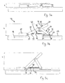
- the connection axis 34 is arranged in a middle transition section of the first support element 18, in which the plate section 26 merges into the two parallel webs 28. In this way, the first support member 18 and the second support member 30 together form an inverted Y-shaped lever arrangement (see also FIGS. 3a to 3c ).
- the upper plate section 26 could also be completely dispensed with, so that the support surface 20 is arranged in the region of the connection axis 34.
- the first support member 18 and the second support member 30 then form together an inverted V-shaped lever arrangement.
- the webs 32, 32 are connected to each other via a transverse web 36, so that the second support member 30 is formed substantially U-shaped.
- the crossbar 36 is orthogonal to the ski longitudinal direction L and parallel to the ski longitudinal surface 22. With the transverse web 36 and with the lower ends of the webs 32, 32, the second support member 30 is supported on a mating support portion 38 of a plate 16 attached to the ski 40.
- the connecting shaft 34, the pivot axis 24 and the counter support portion 38 and the crossbar 36 describe a force triangle, about which a force acting on the support surface 20 compressive force of a ski boot or a cleat is stably introduced into the ski 16.
- the force triangle the climbing aid is secured against tilting along the ski longitudinal direction L, wherein by the transverse web 36 of the second support member 30 and the spaced webs 28, 28 of the first support member 18, a stable grip against tilting is ensured perpendicular to the ski longitudinal direction L.
- the height of the support surface 20 above the surface 22 of the ski 16 and thus the height h of the climbing aid 12 per se can be changed by changing the distance between the pivot axis 24 and the crossbar 36, more precisely by a movement of the crossbar 36 effect on the skifest positioned pivot axis 24 to or from this away.
- the angle ⁇ between the first support member 18 and the second support member 30 changes, so that the first support member 18 and with this the support surface 20 applies to the ski 16 or stands out from it.
- the height of the climbing aid can be adjusted from a minimum value of approximately 14 mm to a maximum value of approximately 76 mm.
- a hydraulic actuator 42 is used, which hereinafter with reference to the Figures 1 to 3c is explained in more detail.
- the hydraulic actuator 42 has a housing 43, the upper half in the Figures 1 to 3b for illustrative purposes, so that the interior of the actuator 42 is visible. Only in Figure 3c is indicated by dashed line the course of the complete housing.
- the hydraulic actuator 42 comprises a piston-cylinder assembly 44 with a cylinder 46 formed as a cavity in the housing 43 and a piston 46 inserted into the cylinder 46.
- the piston 48 is held on a piston rod 50, which at the opposite, from the cylinder 46 exiting end is connected to the transverse web 36 of the second support member 30. Since the housing 43 in Figures 1 to 3b is shown cut along a plane containing the piston rod 50 and the upper half of the housing is not shown is in the Figures 1 to 3b Also, the upper half of the cylinder can not be seen, so that the piston 48 and the piston rod 50 are exposed.
- an inner space of the cylinder 46 is divided into a first hydraulic chamber 52 and a second hydraulic chamber 54.
- the hydraulic chambers 52, 54 are connected to each other via hydraulic lines 56a, 56b, 56c, 56d, 56e, wherein in this connection (in the exemplary embodiment in hydraulic line 56c) a valve 58 is arranged, which can block or connect the hydraulic line 56c in hydraulic communication connection.
- the interior of the cylinder 46 and the hydraulic lines 56a ... 56e is filled with hydraulic fluid.
- hydraulic fluid can flow from one hydraulic chamber into the other hydraulic chamber via the hydraulic lines 56a... 56e and the valve 58 during a movement of the piston 48 in the cylinder 46, so that the piston 48 and thus the crosspiece 36 for adjusting the Height of the climbing aid 12 can move.
- the second hydraulic chamber 54 is also connected to a surge tank 60 via a hydraulic line 56f connected, which receives a variable supply of hydraulic fluid.
- a biased by a spring 61 piston 62 is provided to compensate for the variable volume of the surge tank 60 .
- a coil spring 64 is arranged, which is wound around the piston rod 50, and on the one hand on the piston 48 and on the other hand on the transverse web 36 facing inner end of the cylinder 46 is supported.
- the spring 64 biases the piston 48 in the retraction direction, i. in the direction of a shortening of a distance between the transverse web 36 and axis 24 and thus in the direction of increasing the support surface 20 of the climbing aid 12.
- the spring 64 and the spring 61 are coordinated so that the spring 61 of the surge tank 60 is not the force of the spring 64th overcomes and moves the piston 48 in the extension direction.
- the valve 58 could be operated directly.
- the valve 58 is connected as a solenoid valve via a control line 66 to a control electronics 68, which is located in a housing adjacent to the actuator 42.
- the control electronics 68 comprises an in FIG. 2 only schematically indicated wireless receiver 70 (eg radio receiver), which is in wireless communication with a built-in ski pole 14 wireless transmitter 72 (eg radio transmitter) to receive from the wireless transmitter 72 wireless information about an adjustment process to be triggered. Based on the received wireless information, the wireless receiver 70 sets a control signal, which is transmitted via the control line 66 to the valve 58 to switch the valve 58.
- the control electronics 68 also includes the for the operation of the Wireless receiver 70 necessary power supply, in particular a battery and associated electronics.
- position sensors 71 can be seen, which are arranged along the displacement path of the piston 48 spaced apart on the cylinder 46.
- the position sensors 71 detect a position of the piston 48 within the cylinder 46 and register at least a passing of the piston 48 on one of the position sensors 71.
- the position sensors 71 transmit a position signal to the control electronics 68.
- the adjusting element 42 has an emergency unlocking device, which comprises a bridging valve 63 and hydraulic lines 56g, 56h, 56i.
- the hydraulic lines 56g, 56h, 56i form a bypass for bypassing the valve 58.
- the bypass valve 63 e.g. by a manually operable switch to open a connection between first and second hydraulic chambers 52, 54.
- the climbing aid 12 can then be manually moved to the desired position.
- An alternative emergency release could be provided by having the first support member 18 or the second support member 30 at one of the three points of the power riddle, i. can be posted on the mating support portion 38, on the pivot axis 24, or on the connecting shaft 34, so that the climbing aid 12 can be folded at least in the lowest position in case of malfunction of the actuating element, or the electronics 68.
- the already mentioned wireless transmitter 72 is integrated together with a battery 74 for powering the wireless transmitter 72 inside the handle 73, so that it is well protected against cold and moisture.
- the wireless transmitter 72 includes a wireless end circuit 75, a rocker switch 76, and a display 77.
- the rocker switch 76 is disposed on an upper ski-facing portion of the handle 73 so that it is easily accessible and operable by a skier's thumb.
- the rocker switch 76 has an upper switching section 78, with which an increase in the climbing aid 12 is instructed by one step, and has a lower switching section 80, with which a lowering of the climbing aid 12 is instructed by one step.
- the rocker switch 76 is connected to the wireless end circuit 75 to set a corresponding wireless signal in response to an operation of the rocker switch 76.
- the display device 77 includes four light emitting diodes 82 arranged on an upper front portion of the handle 73 in a row on an imaginary continuation line through the lower switching section 80 and the upper switching section 78.
- the LEDs 82 are powered by the battery 74 with energy and operated by an electronic unit, not shown in accordance with the currently set height of the climbing aid 12.
- the four light emitting diodes each indicate one of four stages in which the height of the climbing aid 12 can be changed by respective actuation of the rocker switch 76.
- the skier In operation of the ski equipment 10, the skier operates to change the height of the climbing aid 12 the rocker switch 76.
- the upper switching section 78 of the wireless transmitter 72 By pressing the upper switching section 78 of the wireless transmitter 72 sends a wireless signal to the wireless receiver 70 of the climbing aid 12, which then transmits a corresponding control signal to the valve 58 , Further, the corresponding light emitting diode 82, which corresponds to the level now to be set, is turned on.
- the valve 58 opens, so that a hydraulic connection between the first and second hydraulic chamber 52, 54 is produced (actuator 42 dearretiert).
- the piston 48 By the force of the spring 64, the piston 48 is then pushed further into the cylinder 46, so that the transverse web 36 continues to move toward the pivot axis 24, thereby hiring the first support element 18 and increasing the height of the support surface 20.
- the valve 58 can be opened either only for a certain time via a timing mechanism or the position of the piston 48 is detected via the position sensors 71, so that as soon as the piston 48 is detected by the next position sensor 71, the control electronics 68, the valve 58 again switches to the blocking state (actuator 42 locked), whereupon the adjusting operation is completed.
- a wireless signal for reducing the height of the climbing aid 12 is lowered by one step and the light-emitting diode display 82 is switched over accordingly.
- the control electronics 68 switches the valve 58 in the open state, so that a displacement of the piston 48 and thus an adjustment of the climbing aid 12 is made possible (actuator 42 dearretiert).
- the displacement of the piston 48 must be done to reduce the height of the climbing aid 12, however, against the action of the spring 64. For this purpose, it is necessary that the skier exerts slight pressure on the support surface 20 or stands with his full weight on the climbing aid 12.
- the control electronics 68 switches the valve 58 back to the blocking state, so that the lowering of the climbing aid 12 is completed by one stage.
- the climbing aid is always pushed down by the force of the skier in the downward direction to the position with minimum height and then after relief of the climbing aid 12, a gradual increase in the climbing aid 12 is possible.
- both wireless receivers 70 and wireless transmitters 72 are designed as wireless transceivers, so that both elements can both transmit and receive wireless signals in order to enable wireless communication also in the direction from the climbing aid to the ski pole. This can be exploited to transmit a successful adjustment of the climbing aid or another operating state of the climbing aid to the wireless end receiver of the ski pole to reliably display the set height of the climbing aid or the operating state of the climbing aid on the display device.
- FIG. 6 shows a grip portion of a ski pole 14 'of equipment according to a second embodiment of the invention.
- the ski pole 14 'of the second embodiment differs from the ski pole 14 of the first embodiment only in construction and operation of the operation switch 76' and the display direction 82 '.
- the actuating switch 76 ' is designed as a rotary switch and comprises an actuating lever 84' which is mounted about an axis 86 'pivotally mounted on the ski pole 14'.
- the operating lever 84 ' may be adjusted by the skier to various angular positions corresponding to respective adjustment stages of the associated climbing aid (not shown).
- the skier can thus quickly adjust the actuating lever 84 'over several stages away in the desired level, and thus immediately instruct the desired change in the height of the climbing aid and run.
- it does not have to actuate the actuating device 76 'several times, as was necessary in the first embodiment by the use of the rocker switch 76.
- the actuating lever 84 ' is connected to a circular segment-shaped display element 88', which extends from the actuating lever 84 'upwards and forwards into the region of a display window 90', so that a section of the display element 88 'can be seen in the window 90'.
- the display element 88 ' carries the adjustment steps of the climbing aid corresponding markings, so that at the corresponding setting angles of the actuating lever 84' of the set levels corresponding marking of the display element 88 'through the window 90' is displayed. In this way, a simple mechanical display capability is realized and an electronic display can be dispensed with.
- the wireless transmitter 72 'of the second embodiment is adapted to convert a signal corresponding to a certain angular position of the actuating lever 84' into a corresponding wireless signal to cause the climbing aid to adjust the corresponding height.
- the wireless transmitter 72 ' can either settle the necessary number of Einzeldrahtlossignalen to increase or decrease the climbing aid by exactly one level or can settle a signal for adjusting the climbing aid by a certain number of levels or can provide a signal for setting the climbing aid in a predetermined level send.
- the wireless receiver 70 'and the wireless transmitter 72' can each be designed as a wireless transceiver for bidirectional communication between the two elements, so that a set level of climbing or other operating condition can be suitably signaled to the skier.
- the wireless transmitter 72; 72 ' can be provided as a retrofit element with which a conventional ski pole with wireless end functionality according to the invention can be retrofitted to operate a wireless communication adjustable ski binding of the invention.
- the retrofittable wireless transmitter could include a suitable universal retention means for temporary or permanent mounting to the handle portion of a ski pole.
- the wireless transmitter which may also function as a receiver, could however also be accommodated on the skier's clothing or other equipment, such as e.g. in the chest area on the carrying strap of a backpack or on the ski or on the ski binding in front of the ski binding for operation by means of the ski pole tip.
- the wireless communication is preferably realized by a radio communication.
- infrared signals or ultrasonic signals could be exchanged between transmitter and receiver.
- FIGS. 7a to 7c With reference to FIGS. 7a to 7c will be explained below a climbing aid according to a third embodiment of the invention.
- the climbing aid of the third exemplary embodiment differs in principle from the climbing aid of the first exemplary embodiment in the use of an electrically operated threaded spindle arrangement 42 "as an adjusting element instead of the hydraulic piston-cylinder arrangement of the first exemplary embodiment as output member a threaded spindle 50 "rotatably drives.
- Electric motor 46 "and threaded spindle 50" extend parallel to the ski longitudinal axis L. The electric motor 46 "is attached to the ski 16.
- a nut 51 (eg a ball nut).
- the nut 51 is received between the webs 32 of the second support member 30 and connected to an axis 53" pivotally connected to the lower ends of the webs 32.
- the threaded spindle assembly 42 "with its elements electric motor 46", threaded spindle 50 "and nut 51” one attached to the ski 16 counter support portion on which the second support member 30 with the axis 53 "is supported.
- the electric motor 46 communicates with control electronics 68" which inter alia include a wireless receiver (not shown) for receiving wireless signals from an associated wireless transmitter (not shown, for example, integrated in the ski pole) and sending appropriate control signals to the electric motor 46 ".
- Control electronics 68 "and electric motor 46" are powered by a battery 92 "with energy.
- a change in a height h of the support surface over the surface of the ski 16 takes place after receiving a corresponding wireless signal by controlling the electric motor 46 ", which puts the threaded spindle 50" in rotation. Accordingly, the nut 51 "of the second support member 30 moves in a linear direction along the ski longitudinal axis L on the electric motor 46" to or from this away, so that applies the climbing aid or sets up.
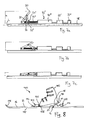
- FIG. 8 shows a fourth embodiment of the invention in a schematic cross-sectional view.
- a touring ski binding generally designated 100, includes a front binding member 102 and a rear binding member 104 fixedly mounted on a ski 16.
- the front binding part has a pivot bearing 106 on which a toe section 108 of a ski boot 110 is held so that the ski boot 110 can pivot about a pivot axis formed by the pivot bearing 106, perpendicular to the longitudinal direction L and parallel to the surface 22 of the ski 16 extending pivot axis.
- the rear binding part comprises a climbing aid 12, for example a climbing aid according to one of the exemplary embodiments explained above, and a heel mount 112.
- the heel mount 112 is displaceable in the longitudinal direction L in order to engage a heel-side projection 114 of the ski boot 110 in a manner known per se. to keep the ski boot 110 in the event of a downhill skiing in the heel section. For one Ascent, especially if at the bottom 115 of the ski 16 a in FIG. 8 not shown riser is glued, the heel holder 112 is moved backwards and releases the heel projection 114 free. The ski boot 110 can then lift upwards and is supported in the downward direction on the support surface 20 of the climbing aid 12.
- the height of the climbing aid 12 is adjustable by means of an adjusting element (for example with the piston-cylinder arrangement 42 of the first exemplary embodiment or the threaded spindle arrangement 42 of the second exemplary embodiment.)
- the ski binding 110 comprises of the fourth embodiment, an actuating button 116, which is provided on the front binding portion 102. More specifically, the actuating button 116 is located between the pivot bearing 106 and a ski tip 118. The actuating button 116 is therefore easy to reach for the skier and can, for example by means of a ski pole, If a display device is located at a comparable location, then this is also clearly visible to the skier.
- actuation button 116 and the adjusting element of the climbing aid 12 is an in FIG. 8 not shown connection to transmit an operating instruction from the actuating button 116 to the actuator.
- Actuation of the actuation button 116 may also affect other binding or binding adjustment, eg, movement of the rear heel holder 112.
- a signal transmitted by a wireless transmitter eg, the wireless dock integrated in the first and second embodiments
- receive a wireless receiver of the ski binding 100 receive a wireless receiver of the ski binding 100 and perform an adjustment of the climbing aid 12 or other binding adjustment or binding adjustment, eg a movement of the rear heel holder 112th
- the pivot axis 24 of the first support member 18 could coincide with the pivot axis of the pivot bracket 106, so that the first support member 18 in the manner of a pivoting cleat supports the ski boot 110 substantially over its entire sole length.
- the ski boot 110 could then also be fixedly mounted on the first support element 18, held.
- FIGS. 9 and 10 show a fifth embodiment of the present invention, which is a further modification of the first embodiment, so that in the following only the elements and functions deviating from the first embodiment will be described and otherwise expressly to the detailed description of the first embodiment with reference to FIGS. 1 to 5 is referenced. Also in FIGS. 9 and 10 For example, an upper half of a housing 202 is cut off for illustrative purposes, so that the interior of a locking mechanism 204 is visible.
- the locking mechanism 204 comprises a locking rod 206, which is coupled at one end to the transverse web 36 of the second support member 30 and slidably inserted with the other end in a cylindrical guide 208.
- the cylindrical guide 208 is formed in the housing 202 so that an upper half of the cylindrical guide 208 in FIG FIGS. 9 and 10 not shown.
- the locking rod 206 can move in the longitudinal direction L to move the crosspiece 36 of the second support member 30 to the axis 24 of the first support member 18 to or away.
- the latching rod 206 has a spring stop 210, in the embodiment an orthogonal to the ski longitudinal axis L extending strut. Between the spring stop 210 and the housing 202 acts at least one spring 212 to the locking rod 206 in the retraction direction in the cylindrical guide 208th pretension, so that the climbing aid sets up.
- two springs 212 are held on both sides of the cylindrical guide 208 in pot-like spring guides 214, so that they are supported on the floor 216 of the spring guides 214 on the one hand and on the spring stop 210 on the other hand and held in the compressed state.
- the locking rod 206 has a plurality of locking grooves 218, which are arranged with respect to the ski longitudinal axis L at intervals from each other.
- the latching grooves 218 are designed as annular grooves. In the locking grooves engages a locking projection 220, which is part of an actuating element 221.
- the adjusting element 221 is adjustable between a locking position in which the locking projection 220 is engaged with one of the locking grooves 218 and thus a displacement of the locking rod 206 is blocked in the cylindrical guide 208 (change in the height of the climbing aid blocked), and a dearretierposition, in which retracts the locking projection 220 and is not engaged with any of the locking grooves 218 so that the locking bar 206 can move in the cylindrical guide 208 (change in the height of the climbing aid released).
- the actuator 221 includes a piston 222 and a cylinder 224, in which the piston 222 is slidably inserted.
- the locking projection 220 is formed and protrudes from the cylinder 224.
- a spring 226 acting between the cylinder 224 and the piston 222 biases the piston 222 toward the locking rod 206, so that the locking projection 220 is pressed into the engagement position with a latching groove 218.
- an electromagnet 228 is arranged, which attracts the piston 222 when energized and retracts against the force of the spring 226 from the latching engagement. As long as the solenoid 228 is energized, the locking projection 220 is held in the retracted position and the actuator 221 remains in the Dearretierposition.
- the locking projection 220 is pressed by the force of the spring 226 in the direction of the locking rod 206 and passes or remains in engagement with a arranged at the same position locking groove 218 of the locking rod 206.
- the solenoid 228 is connected via a control line 230 of the control electronics 68 supplied, so that the control electronics 68, the control element 221, eg switch between the lock position and the dearretier position based on a wireless signal received from a wireless receiver 70.
- the skier actuates the adjusting element 221 by a suitable actuating means, in particular by wireless operation of the ski pole 14 via the wireless receiver 70 and the control electronics 68, so that the control 221 switches to the dearretierposition.
- the movement of the locking rod 206 in the cylindrical guide 208 is now released, so that the height of the climbing aid is variable.
- An upward movement of the climbing aid can be done by reducing the pressure force by the skier on the climbing aid, so that the springs 212 can move the locking rod 206 in the retraction and erects the climbing aid.
- a reduction in the height of the climbing aid can be done by increasing the pressure of the skier on the climbing aid, so that the force of the springs 212 is overcome and the climbing aid is depressed.
- the actuator 221 is switched from the Dearretierposition in the locking position (de-energizing the electromagnet 228), so that the locking projection 220 is pressed to the locking rod 206 back. If the locking projection 220 strikes straight into a locking groove 218, the climbing aid is locked immediately and a further height adjustment is blocked.
- the latching projection 220 is located just between two locking grooves 218, so depending on the pressing force of the skier on the climbing aid of the locking piston 206 itself move either in the retraction or in the extension direction, wherein the locking projection 220 slides on the locking piston 206 until a next locking groove 218 the locking projection 220 is opposite and the locking projection 220 engages in the locking groove 218. The adjustment of the climbing aid is then completed.
- the fifth embodiment may include a position detecting means which detects the position of the detent rod 206 in the cylindrical guide 208 or which detects in which of the detent grooves 218 of the detent projection 220 is engaged to on the basis of this detection result, the setting level of the climbing aid to the skier signal.
- a dearretier mechanism 304 of the sixth exemplary embodiment has two actuating elements 321a, 312b, which are each independently controllable by the control electronics 68 through respective control lines 330a, 330b.
- the adjusting elements 321a and 321b are each equipped with a piston 322a or 322b, which is prestressed in the direction of a locking bar 306, which each have a latching projection 320a or 320b.
- the locking projections 320a, 320b of the sixth embodiment have However, one-sided whilschrägen 323a, 323b, each of which allow the displacement of the locking rod in a direction displacing the piston 322a and 322b, however, block a displacement of the locking rod 306 in the opposite direction.
- the downcomers 322a, 322b of the two actuators 321a, 321b are oppositely directed, so that when both actuators 321a, 321b are in the engaged position (displaced in the direction of the latch rod 306, electromagnets 328a, 328b are turned off) the latch rod 306 is in both directions is blocked.
- the skier actuates out of a certain locking position of the climbing aid
- an operating switch in the sense of a downward movement of the climbing aid (eg, a down-switch on the ski pole) to lower the climbing aid by a locking position.
- the control electronics 68 energize the solenoid 328a of the first actuator 321a while the solenoid 328b of the second actuator 321b remains de-energized.
- the climbing aid remains at the previously set height, since the second adjusting element 321b prevents movement of the locking rod 306 in the sense of an outward movement of the climbing aid. If the skier applies sufficient pressure to the climbing aid, i. a pressure exceeding the force of the springs 312, so the locking bar 306 slips over the drainage slope 323b of the second control element 321b, so that the height of the climbing aid is reduced. This movement continues until the solenoid 328a of the first actuator 321a is de-energized, e.g. upon reaching the desired next detent step, so that then an adjustment of the climbing aid is blocked again in both directions.
- the pivoting movement of the latch can be controlled by an electromagnet, which in this case the additional advantage that can be created by the pivotal mounting of the latch a lever assembly with different lengths levers, of which a longer lever provides the locking tooth and a shorter lever from the electromagnet is tightened or released, so that a relatively high travel of the locking tooth between the engaged position and disengaged position is possible with only small Anteuerungsweg of attracted by the electromagnet or released second lever.
- FIG. 12 shows a climbing aid according to a seventh embodiment of the invention.
- the seventh embodiment is a modification of the first embodiment which has been described above in detail with reference to FIG FIG. 2 have been described.
- FIG. 12 are the same or corresponding elements as designated in the first embodiment with reference numerals increased by 400 and their re-description is omitted. It is expressly made in this regard to the detailed description of the first embodiment.
- the already mentioned in the sixth embodiment effect is achieved that an adjustment for the climbing aid can be specified by the skier, with an unintentional adjustment is prevented in the non-directed direction.
- the first hydraulic chamber 452 and the second hydraulic chamber 454 are connected to each other by two parallel hydraulic branches 457a and 457b.
- the first hydraulic branch 457a has a series connection of a one-way valve 459a and a switchable valve 458a.
- the second hydraulic branch 457b has a series connection of a one-way valve 459b and a switching valve 458b.
- the one-way valve 459a of the first hydraulic branch 457a is directed to allow fluid flow from the second hydraulic chamber 454 to the first hydraulic chamber 452 but to block fluid flow in the opposite direction.
- the one-way valve 459b of the second hydraulic branch 457b is opposite to the first one-way valve 459a, ie, it allows fluid flow from the first hydraulic chamber 452 to the second hydraulic chamber 454 and blocks an opposing fluid flow.
- the switching valve 458a of the first hydraulic branch 457a is closed by appropriate signals of the control electronics 68 and the switching valve 458b of the second hydraulic branch 457b is opened. Hydraulic fluid may then flow between the first hydraulic chamber 452 and the second hydraulic chamber 454 only via the second hydraulic branch 457b which, due to the one-way valve 459b, allows only flow from the first hydraulic chamber 452 into the second hydraulic chamber 454 but blocks reverse flow. Accordingly, in this switch position, the piston 448 can only be moved in the extension direction, i. The climbing aid can only be pushed downwards and will not move upwards in an undesired manner when it is relieved.
- the switching valve 458a of the first hydraulic branch 457a is opened, and the switching valve 458b of the second hydraulic branch 457b is closed so that hydraulic fluid from only the second hydraulic chamber 454 into the first hydraulic chamber due to the one-way valve 459a 452 can flow and thus the piston 448 is displaceable only in the retraction direction.
- the climbing aid can then be moved upwards with relief, but a depression of the climbing aid is avoided even under heavy load.
- the locking rod 206 of the fifth embodiment may be formed by a piston rod of a piston-cylinder assembly on the model of the first embodiment, so that such a variant comprises a total of two control elements, one for changing the height of the climbing aid and a second for locking or Dearret mich the height adjustment.
- Actuators were used with hydraulic piston-cylinder arrangement.
- a gas spring could be used, which would provide additional benefits of lighter weight and less component count.
- due to the compressivity of gas on the spring 64 and / or on the surge tank 60 could be omitted.
- a gas spring can be effectively blocked or released by means of a valve and thus allows easy control.
Landscapes
- Footwear And Its Accessory, Manufacturing Method And Apparatuses (AREA)
- Drawing Aids And Blackboards (AREA)
Abstract
Description
- Die vorliegende Erfindung betrifft eine Gleitbrettausrüstung, umfassend eine auf einem Gleitbrett montierbare Bindung, welche insbesondere eine Tourenskibindung aber auch eine Langlaufskibindung oder eine Abfahrtsskibindung sein kann. Unter dem Begriff Gleitbrettausrüstung soll im Sinne der vorliegenden Erfindung ferner auch Snowboardausrüstung, einschließlich einer Snowboard-Bindung, verstanden werden. Ferner betrifft die Erfindung eine Bindung für ein Gleitbrett, insbesondere eine Tourenskibindung.
- Herkömmliche Bindungen weisen zumeist mindestens eine Verstellmöglichkeit auf, so z.B. die Öffnung oder Schließung der Bindung zum Einsteigen in die Bindung bzw. zum Aussteigen aus der Bindung, die Verstellung der Auslösekraft für die Öffnung der Bindung im Sturzfalle, die Fixierung des Fersenabschnitts des Schuhs im Falle von Langlaufskiern bzw. die Lösung dieser Fixierung, eine Feinpositionierung des Schuhs usw.
- Für Tourenski oder Splitboards (in Längsrichtung teilbare Snowboards, welche für den Aufstieg in der Art von Skiern verwendet werden) kommen spezialisierte Bindungen zum Einsatz, welche zumindest zwischen zwei Betriebszuständen verstellbar sind: einem Aufstiegszustand, in welchem der Schuh oder eine den Schuh tragende Schuhplatte nur im Bereich der Schuhspitze schwenkbar mit dem Gleitbrett verbunden ist, während der Schuh im Fersenbereich vom Gleitbrett abheben kann, sowie einem Abfahrtszustand, in welchem der Schuh oder eine den Schuh tragende Schuhplatte sowohl im Bereich der Schuhspitze als auch im Fersenbereich des Schuhs am Gleitbrett fixiert ist. Für die Verwendung bei stärker ansteigendem Gelände haben sich Tourenbindungen mit einer Steighilfe bewährt, welche eine Auflagefläche für den Fersenabschnitt des Schuhs oder für die Schuhplatte aufweist, wobei die Auflagefläche in einem bestimmten Abstand über dem Gleitbrett angeordnet ist, so dass sich der Benutzer im Fersenbereich auf der Auflagefläche der Steighilfe abstützen kann.
- In bekannten Tourenskibindungen ist ein im Fersenbereich angeordnetes Bindungsteil verschiebbar oder verdrehbar zwischen einer ersten Position, in der der Skischuh am Ski fixiert ist (Abfahrtszustand), einer zweiten Position, in welcher der Skischuh im Fersenbereich freigegeben ist (Aufstiegszustand für flaches Gelände) und einer dritten Position, in welcher das Bindungsteil in eine Position unterhalb des Fersenabschnitts des Skischuhs oder der Schuhplatte verschoben ist, um eine Steighilfe bereitzustellen (Aufstiegszustand für steileres Gelände). Als Beispiel für eine solche Steighilfe kann auf die
EP 0 724 899 A2 verwiesen werden. - Ein Nachteil bekannter Gleitbrettausrüstungen mit Bindung liegt darin, dass eine Verstellung bzw. Betätigung der Bindung relativ mühsam ist und ein Anhalten des Benutzers sowie eine relativ unbequeme Bewegung des Benutzers erforderlich ist, um den Mechanismus der Bindung zu erreichen und zu verstellen bzw. zu betätigen. Oftmals muss der Benutzer aus der Bindung aussteigen um eine Verstellbewegung durchzuführen. Eine Verstellung oder Betätigung der Bindung ist somit zumeist auch zeitaufwendig und kann unter Umständen gefährlich sein.
- Aufgabe der vorliegenden Erfindung ist es, eine Gleitbrettausrüstung mit einer Bindung bereitzustellen, welche sich schneller und einfacher verstellen oder betätigen lässt, um den Komfort und die Sicherheit für den Benutzer zu verbessern.
- Erfindungsgemäß wird diese Aufgabe gelöst durch eine Gleitbrettausrüstung, umfassend eine auf einem Gleitbrett montierbare Bindung, ein an der Bindung vorgesehenes Stellelement zum Bewirken einer Verstellung oder Betätigung der Bindung, einen an der Bindung vorgesehenen Drahtlosempfänger zum Empfang einer Drahtlosinformation, und einen Drahtlossender zur Abgabe der Drahtlosinformation, wobei das Stellelement die Bindung auf Grundlage der empfangenen Drahtlosinformation verstellt oder betätigt.
- Erfindungsgemäß ist somit eine Drahtlosverbindung zwischen einem Drahtlossender und einer Bindung einer Gleitbrettausrüstung vorgesehen, wodurch eine höchst komfortable Möglichkeit zur Ausführung einer Verstellung oder Betätigung der Bindung geschaffen wird. Eine Drahtlosverbindung ermöglicht eine flexible Wahl der Position des Drahtlossenders und des Drahtlosempfängers und bietet vielfältige Möglichkeiten für die Übertragung einer spezifischen Drahtlosinformation zur Ausführung einer bestimmten Verstellung oder Betätigung der Bindung. Auf diese Weise können Auslösecharakteristiken (z.B. eine Auslösekraft) einer Abfahrtsbindung für Skier oder Snowboards verstellt werden, ein Freigabemechanismus oder ein Fixerungsmechansimus für einen Fersenbereich eines Schuhs in einer Tourenbindung, einer Abfahrtsbindung oder einer Langlaufbindung betätigt werden oder eine Bindung für den Einstieg oder Ausstieg geschlossen bzw. geöffnet werden. Auch andere Justiermechanismen, etwa zur Veränderung einer Position oder Orientierung des Schuhs am Gleitbrett können in Ausführungsvarianten der Erfindung durch die Drahtloskommunikation vom Benutzer komfortabel angewiesen werden.
- Für die Verstell- bzw. Betätigungsvorgänge muss der Benutzer keine mühsame, zeitaufwendige oder sogar gefährliche Bewegung vornehmen, so dass er nicht aus der Bindung aussteigen oder gar ein Werkzeug zu Hilfe nehmen. Der Drahtlossender kann als mobiler Sender an für den Benutzer bequem zu erreichender Position mitgeführt werden, so dass sich der Benutzer für die Verstellung oder Betätigung nicht bücken muss.
- Besonders bevorzugt kommt die erfindungsgemäße Drahtloskommunikation für Tourenbindungen zum Einsatz, welche eine Steighilfe umfassen, wobei die Steighilfe einen Auflageabschnitt aufweist, an welchem eine dem Gleitbrett abgewandte Auflagefläche für den Fersenabschnitt eines Schuhs oder eine Schuhplatte in einer Höhe über dem Gleitbrett vorgesehen ist. Die erfindungsgemäß übertragene Drahtlosinformation vom Drahtlossender an den Drahtlosempfänger könnte dann beispielsweise eine Verstellung der Bindung zwischen einem Abfahrtszustand und einem Aufstiegszustand oder eine Verstellung der Höhe der Steighilfe bewirken oder könnte die Steighilfe umschalten zwischen einer Dearretierungstellung, in welcher eine Verstellung oder Betätigung der Steighilfe möglich ist, und einer Arretierstellung, in welcher eine Verstellung oder Betätigung der Steighilfe blockiert ist. Für den Vorgang der Verstellung oder Betätigung der Bindung muss der Benutzer lediglich den Drahtlossender aktivieren oder deaktivieren, so dass der Verstell- oder Betätigungsvorgang einfacher, schneller und sicherer ausgeführt werden kann.
- Für eine erfindungsgemäße Gleitbrettausrüstung mit höhenverstellbarer Steighilfe sind mehrere Ausführungsvarianten denkbar, von denen drei Ausführungsvarianten im folgenden beschrieben werden, wobei die Ausführungsvarianten ggf. auch in Kombination miteinander verwendet werden können.
- In einer ersten Ausführungsvariante ist vorgesehen, dass das Stellelement auf Grundlage der empfangenen Funkinformation eine eingestellte Höhe der Steighilfe über dem Gleitbrett arretiert oder/und eine solche Arretierung löst. Diese Ausführungsvariante kann mit technisch relativ einfachen Mitteln kostengünstig und mit geringem Gewicht realisiert werden, da insbesondere eine Arretierbewegung bzw. Dearretierbewegung durch ein Stellelement mit geringem Stellweg realisiert werden kann.
- Gemäß einer zweiten Ausführungsvariante könnte eine Verstellbewegung der Höhe der Steighilfe mit einer Verstellbewegung des Stellelements bewegungsgekoppelt sein und das Stellelement könnte auf Grundlage der empfangenen Funkinformation in einem eingestellten Verstellzustand arretierbar oder/und aus einer Arretierung lösbar sein. Das Stellelement kann dann zum einen die Verstellbewegung der Höhe der Steighilfe beeinflussen (z.B. dämpfen oder führen oder antreiben) und zum anderen als Arretiermittel dienen.
- In einer dritten Variante kann das Stellelement auf Grundlage der empfangenen Funkinformation die Höhe der Steighilfe über dem Gleitbrett verstellen. Das Stellelement weist dann insbesondere einen eigenen Antrieb auf, um eine Verstellung der Höhe der Steighilfe zu bewirken. Wenn die Verstellung der Höhe der Steighilfe allein durch Wirkung des Stellelements ausgeführt wird, so ist eine solche Variante besonders komfortabel.
- Das Stellelement einer erfindungsgemäßen Gleitbrettausrüstung kann allgemein ein elektrisch, pneumatisch oder hydraulisch betätigbares Stellelement sein. Elektrisch, pneumatisch oder hydraulisch betätigbare Stellelemente können mit technisch einfachen Mitteln elektrisch oder elektronisch auf Grundlage der vom Drahtlosempfänger empfangenen Drahtlosinformation angesteuert werden.
- In einer bevorzugten Ausführungsform ist vorgesehen, dass das Stellelement eine Kolben-Zylinder-Anordnung ist, umfassend wenigstens einen Zylinder, einen Kolben, welcher in den Zylinder eingeschoben ist, sodass er einen Innenraum des Zylinders in zwei Kammern unterteilt, eine Verbindungsleitung, welche die beiden Kammern verbindet, und ein Ventil, welches in der Verbindungsleitung angeordnet ist, um den Durchtritt von Fluid durch die Verbindungsleitung zu sperren oder zuzulassen, wobei das Ventil auf Grundlage der empfangenen Drahtlosinformation zwischen einem Sperrzustand und einem Durchlasszustand schaltet. Das in der Verbindungsleitung angeordnete Ventil bietet dabei eine einfache und wirkungsvolle Möglichkeit, den Betrieb der Kolben-Zylinder-Anordnung durch elektrische Signale in gewünschter Weise zu beeinflussen, um eine Bewegung der Anordnung nach Maßgabe der empfangenen Drahtlosinformation anzusteuern, zu unterbrechen oder freizugeben. Unabhängig vom verwendeten Bindungstyp kann bei einer erfindungsgemäßen Gleitbrettausrüstung der Drahtlossender mit einem Betätigungselement verbunden sein, welches bei einer Betätigung durch den Benutzer den Drahtlossender veranlasst, eine Drahtlosinformation auszusenden. Somit verstellt oder betätigt die Gleitbrettausrüstung die Bindung entsprechend dem Willen des Benutzers durch einfache Bedienung des Betätigungselements, z.B. eines Tastschalters.
- Der Drahtlossender kann in einer weiteren Ausführungsform mit einem Anzeigeelement oder einer Signalisierungselement verbunden sein, welches eine Information über einen Einstellzustand oder einen Bewegungszustand der Bindung oder über einen Betriebszustand des Drahtlossenders anzeigt oder signalisiert. Als Anzeige kommt insbesondere eine optische Anzeige in Form von Leuchtdioden oder einem mechanischen Anzeigeelement in Betracht. Als Signalisierung wird an eine akustische Signalisierung gedacht.
- Ein Anzeige- oder Signalisierungselement unterstützt das vom Benutzer der Gleitbrettausrüstung entgegengebrachte Vertrauen in eine zuverlässige und nach dem Willen des Benutzers eingestellte Betriebsposition durch Ermöglichung einer visuellen oder akustischen Rückkopplung. Der Benutzer muss insbesondere nicht auf die gefühlte Höhe der Steighilfe vertrauen oder versuchen, die Höhe der Steighilfe durch eine unbequeme Bewegung direkt zu erkennen.
- In einer weiteren vorteilhaften Ausführungsform umfasst die Gleitbrettausrüstung ferner einen Stock, z.B. einen Skistock, wobei der Drahtlossender an dem Stock angeordnet ist. Auf diese Weise ist der Drahtlossender einerseits verliersicher als Teil eines üblichen Ausrüstungselements gehalten und kann andererseits auch kostengünstig im Stock integriert sein, so dass ein zusätzliches Gehäuse für den Drahtlossender nicht erforderlich ist.
- Besonders wird die Anordnung des Betätigungselements oder/und des Anzeigeelements an einem Griffabschnitts des Stocks ins Auge gefasst, was darüber hinaus eine komfortable Betätigung des Betätigungselements bzw. eine gute Sichtbarkeit des Anzeigeelements ermöglicht, ohne dass der Benutzer seine Hände vom Stock lösen muss. Der Benutzer kann insbesondere während des Laufens (im Falle einer Tourenausrüstung) einen sicheren Griff des Stocks beibehalten und gleichzeitig, beispielsweise mit einem Finger, das Betätigungselement betätigen, um die Bindung zu verstellen bzw. zu betätigen, insbesondere um die Höhe der Steighilfe einzustellen.
- Der Drahtlossender könnte ferner ein Haltemittel zur Anbringung an einem Stock aufweisen, so dass auch ein herkömmlicher Stock mit der erfindungsgemäßen Ausrüstung zur Drahtloskommunikation nachgerüstet werden kann. Alternativ könnten der Drahtlossender und ggf. das Betätigungselement, das Anzeigeelement bzw. das Signalisierungselement, in einem portablen Gehäuse untergebracht sein, das am Körper zu tragen ist oder in einer Tasche des Benutzers untergebracht sein kann und von dort aus bequem bedient werden kann.
- Prinzipiell könnte für die erfindungsgemäße Drahtloskommunikation zwischen Drahtlossender und Bindung eine Ultraschallübertragung oder eine Infrarotübertragung usw. zum Einsatz kommen. Bevorzugt wird jedoch eine Funkkommunikation als Drahtloskommunikation verwendet, da diese eine zuverlässige und schnelle Signalübertragung mit geringem technischen Aufwand erlaubt.
- Nach einem weiteren Aspekt wird die Erfindungsaufgabe gelöst durch eine Bindung für ein Gleitbrett, wobei die Bindung ein Stellelement zum Bewirken einer Verstellung oder Betätigung der Bindung umfasst, wobei die Bindung einen Drahtlosempfänger zum Empfang einer Drahtlosinformation aufweist und wobei das Stellelement die Bindung auf Grundlage der empfangenen Drahtlosinformation verstellt oder betätigt. Eine solche Bindung ist komfortabel durch eine Drahtloskommunikation ansteuerbar, insbesondere fernbedienbar, und erzielt dementsprechend die oben in Bezug auf die erfindungsgemäße Gleitbrettausrüstung näher ausgeführten Vorteile und Effekte. Die Bindung kann in Ausführungsformen ferner mit einem oder mehreren der vorstehend in Bezug auf die Gleitbrettausrüstung beschriebenen Merkmale weitergebildet werden, um die jeweils beschriebenen Vorteile und Effekte zu erzielen.
- Die Erfindung wird nachfolgend anhand bevorzugter Ausführungsbeispiele unter Bezugnahme auf die beigefügten Zeichnungen näher erläutert. Es zeigen:
- Figur 1
- eine perspektivische Ansicht einer Skiausrüstung nach einem Ausführungsbeispiel der Erfindung;
- Figur 2
- eine Funktionsansicht einer Steighilfe der in
Figur 1 dargestellten Skiausrüstung; - Figuren 3a bis 3c
- Seitenansichten der in
Figur 2 dargestellten Steighilfe; - Figur 4
- eine perspektivische Ansicht eines Griffabschnitts eines Skistocks der in
Figur 1 dargestellten Skiausrüstung; - Figur 5
- eine Längsschnittansicht des in
Figur 4 dargestellten Griffabschnitts; - Figur 6
- eine Längsschnittansicht entsprechend
Figur 5 , jedoch für ein zweites Ausführungsbeispiel der Erfindung; - Figuren 7a bis 7c
- Seitenansichten einer Steighilfe nach einem dritten Ausführungsbeispiel der Erfindung;
- Figur 8
- eine schematische Seitenansicht eines Tourenskis mit Skibindung gemäß einem vierten Ausführungsbeispiel der Erfindung;
- Figuren 9 und 10
- Funktionsansichten einer Steighilfe nach einem fünften Ausführungsbeispiel der Erfindung für zwei verschiedene Verstellstufen; und
- Figuren 11 und 12
- Funktionsansichten weiterer Steighilfen nach einem sechsten bzw. siebten Ausführungsbeispiel der Erfindung.
- Eine in
Figur 1 allgemein mit 10 bezeichnete Skiausrüstung nach einem ersten Ausführungsbeispiel der Erfindung umfasst eine Steighilfe 12 sowie einen Skistock 14. Die Steighilfe 12 ist Element eines hinteren Bindungsteils einer auf einem Ski 16 montierten Tourenskibindung. Aus illustrativen Gründen ist inFigur 1 nur ein Abschnitt des Skis 16 dargestellt, wobei ein inFigur 1 rechtes Ende des Abschnitts der Skispitze zugewandt ist, während ein inFigur 1 linkes Ende des Abschnitts dem Skiende zugewandt ist. Die Steighilfe 12 ließe sich jedoch gleichermaßen in umgekehrter Richtung auf dem Ski montieren, so dass bezüglichFigur 1 die Skispitze links und das Skiende rechts angeordnet ist. Bevorzugt ist jedoch die Konfiguration mit Skispitze rechts inFigur 1 , insbesondere um bei kleinen Steigungen Drehmomentbelastungen der Hebelelemente der Steighilfe klein zu halten. - Die Steighilfe 12 des ersten Ausführungsbeispiels wird im folgenden unter Bezugnahme auf
Figuren 1 bis 3 näher erläutert. Ein erstes Stützelement 18 weist an seinem oberen Ende eine Auflagefläche 20 für den Fersenabschnitt eines Skischuhs oder eine den Skischuh haltende Stützplatte auf, und ist am entgegengesetzten unteren Ende an einer parallel zur Oberfläche 22 des Skis 16 und senkrecht zur Längsachse L des Skis 16 verlaufenden Schwenkachse 24 schwenkbar gelagert. Das Stützelement 18 ist gabelartig ausgebildet mit einem oberen Plattenabschnitt 26 und zwei unteren im Abstand voneinander parallel sich von dem Plattenabschnitt 26 aus erstreckenden Stegen 28, welche an Endabschnitten der Schwenkachse 24 jeweils schwenkbar mit dieser gekoppelt sind. - Ein zweites Stützelement 30 umfasst zwei parallele Stege 32, 32, welche an ihren oberen Enden mit den jeweiligen Enden einer Verbindungsachse 34 gekoppelt sind. An der Verbindungsachse 34 ist das zweite Stützelement 30 schwenkbar mit dem ersten Stützelement 18 verbunden. Die Verbindungsachse 34 ist in einem mittleren Übergangsabschnitt des ersten Stützelements 18 angeordnet, in welchem der Plattenabschnitt 26 in die beiden parallelen Stege 28 übergeht. Auf diese Weise bilden das erste Stützelement 18 und das zweite Stützelement 30 miteinander eine umgekehrt-Y-förmige Hebelanordnung (siehe auch
Figuren 3a bis 3c ). - Durch die Länge des oberen Plattenabschnitts 26 kann ein fester Abstand zwischen der Verbindungsachse 34 und der Auflagefläche 20 konstruktiv vorgegeben werden, ohne dass dies Einfluss auf die relative Lage der Gelenkpunkte der Stützelemente 18, 30 zueinander hat. In einer Variante könnte der obere Plattenabschnitt 26 auch ganz entfallen, so dass die Auflagefläche 20 im Bereich der Verbindungsachse 34 angeordnet ist. Das erste Stützelement 18 und das zweite Stützelement 30 bilden dann miteinander eine umgekehrt-V-förmige Hebelanordnung.
- Am zur Verbindungsachse 34 entgegengesetzten Ende sind die Stege 32, 32 miteinander über einen Quersteg 36 verbunden, so dass das zweite Stützelement 30 im Wesentlichen U-förmig ausgebildet ist. Der Quersteg 36 verläuft orthogonal zur Skilängsrichtung L und parallel zur Skilängsoberfläche 22. Mit dem Quersteg 36 sowie mit den unteren Enden der Stege 32, 32 stützt sich das zweite Stützelement 30 auf einem Gegenstützabschnitt 38 einer am Ski 16 befestigten Platte 40 ab.
- Die Verbindungsachse 34, die Schwenkachse 24 und der Gegenstützabschnitt 38 bzw. der Quersteg 36 beschreiben ein Kräftedreieck, über welches eine auf die Auflagefläche 20 einwirkende Druckkraft von einem Skischuh oder einer Schuhplatte stabil in den Ski 16 eingeleitet wird. Durch das Kräftedreieck ist die Steighilfe gegen Verkippen entlang der Skilängsrichtung L gesichert, wobei durch den Quersteg 36 des zweiten Stützelements 30 und die im Abstand voneinander angeordneten Stege 28, 28 des ersten Stützelements 18 ein stabiler Halt gegenüber einer Kippbewegung senkrecht zur Skilängsrichtung L gewährleistet wird.
- Wie in
Figuren 3a bis 3c gut zuerkennen ist, lässt sich die Höhe h der Auflagefläche 20 über der Oberfläche 22 des Skis 16 und damit die Höhe h der Steighilfe 12 an sich durch eine Änderung des Abstands zwischen der Schwenkachse 24 und dem Quersteg 36, genauer gesagt durch eine Bewegung des Querstegs 36 auf die skifest positionierte Schwenkachse 24 zu oder von dieser weg bewirken. Auf diese Weise ändert sich der Winkel α zwischen dem ersten Stützelement 18 und dem zweiten Stützelement 30, so dass sich das erste Stützelement 18 und mit diesem die Auflagefläche 20 an den Ski 16 anlegt oder sich von diesem abhebt. Im Ausführungsbeispiel lässt sich auf diese Weise die Höhe der Steighilfe von einem Minimalwert von ungefähr 14 mm bis zum einem Maximalwert von ungefähr 76 mm verstellen. - Für die Verstellung der Höhe der Steighilfe wird ein hydraulisches Stellelement 42 verwendet, welches nachfolgend unter Bezugnahme auf die
Figuren 1 bis 3c näher erläutert wird. Das hydraulische Stellelement 42 weist ein Gehäuse 43 auf, dessen obere Hälfte in denFiguren 1 bis 3b aus illustrativen Gründen abgeschnitten ist, so dass das Innere des Stellelements 42 sichtbar ist. Nur inFigur 3c ist mit gestrichelter Linie der Verlauf des vollständigen Gehäuses angedeutet. - Das hydraulische Stellelement 42 umfasst eine Kolben-Zylinder-Anordnung 44 mit einem als Hohlraum im Gehäuse 43 ausgebildeten Zylinder 46 und einem in den Zylinder 46 eingeschobenen Kolben 48. Der Kolben 48 ist an einer Kolbenstange 50 gehalten, welche an dem gegenüberliegenden, aus dem Zylinder 46 austretenden Ende mit dem Quersteg 36 des zweiten Stützelements 30 verbunden ist. Da das Gehäuse 43 in
Figuren 1 bis 3b entlang einer die Kolbenstange 50 enthaltenden Ebene geschnitten dargestellt ist und die obere Gehäusehälfte nicht dargestellt ist, ist in denFiguren 1 bis 3b auch die obere Hälfte des Zylinders nicht zu erkennen, sodass der Kolben 48 und die Kolbenstange 50 frei liegen. - Durch den Kolben 48 wird ein Innenraum des Zylinders 46 in eine erste Hydraulikkammer 52 und eine zweite Hydraulikkammer 54 unterteilt. Die Hydraulikkammern 52, 54 stehen über Hydraulikleitungen 56a, 56b, 56c, 56d, 56e miteinander in Verbindung, wobei in dieser Verbindung (im Ausführungsbeispiel in Hydraulikleitung 56c) ein Ventil 58 angeordnet ist, welches die Hydraulikleitung 56c sperren oder in Hydraulikkommunikationsverbindung schalten kann.
- Das Innere des Zylinders 46 sowie der Hydraulikleitungen 56a...56e ist mit Hydraulikflüssigkeit gefüllt. Bei geöffnetem Ventil 58 kann Hydraulikflüssigkeit bei einer Bewegung des Kolbens 48 im Zylinder 46 von einer Hydraulikkammer in die andere Hydraulikkammer über die Hydraulikleitungen 56a...56e und das Ventil 58 strömen, so dass sich der Kolben 48 und damit der Quersteg 36 zur Verstellung der Höhe der Steighilfe 12 bewegen können. Im Sperrzustand des Ventils 58 ist die Verbindung zwischen den Hydraulikkammern 52, 54 unterbrochen und aufgrund der Unkomprimirbarkeit der Hydraulikflüssigkeit und der flüssigkeitsdichten Anlage des Kolbens 48 an der Innenwandung des Zylinders 46 wird eine Verschiebung des Kolbens 48 und damit eine Bewegung des Querstegs 36 blockiert, so dass die Höhe der Steighilfe 12 auch bei Druckausübung durch den Skischuh oder die Schuhplatte auf die Anlagefläche 20 nicht verändert werden kann und stabil bleibt.
- Um das durch die Kolbenstange 50 eingenommene Flüssigkeitsvolumen im Inneren des Zylinders 46 zu kompensieren, ist die zweite Hydraulikkammer 54 ferner über eine Hydraulikleitung 56f an einen Ausgleichsbehälter 60 angeschlossen, welcher einen veränderlichen Vorrat an Hydraulikflüssigkeit aufnimmt. Zum Ausgleich des veränderlichen Volumens des Ausgleichsbehälters 60 ist ein durch eine Feder 61 vorgespannter Kolben 62 vorgesehen.
- Im Inneren des Zylinders 46 ist eine Schraubenfeder 64 angeordnet, welche um die Kolbenstange 50 herum gewunden ist, und sich einerseits am Kolben 48 und andererseits an dem Quersteg 36 zugewandten inneren Ende des Zylinders 46 abstützt. Die Feder 64 spannt den Kolben 48 in Einfahrrichtung vor, d.h. in Richtung einer Verkürzung eines Abstands zwischen Quersteg 36 und Achse 24 und damit in Richtung einer Erhöhung der Auflagefläche 20 der Steighilfe 12. Die Feder 64 und die Feder 61 sind so aufeinander abgestimmt, dass die Feder 61 des Ausgleichsbehälters 60 nicht die Kraft der Feder 64 überwindet und den Kolben 48 in Ausfahrrichtung bewegt.
- Da das Gehäuse 43 in
Figuren 1 bis 3b entlang einer die Kolbenstange 50 und den Kolben 62 enthaltenden Ebene geschnitten dargestellt ist und die obere Gehäusehälfte nicht dargestellt ist (nur inFigur 3c angedeutet), liegen in denFiguren 1 bis 3b auch die Schraubenfeder 64 sowie der federvorgespannte Kolben 62 frei. - Prinzipiell könnte das Ventil 58 direkt betätigt werden. Im Ausführungsbeispiel ist das Ventil 58 als Magnetventil jedoch über eine Steuerleitung 66 mit einer Steuerelektronik 68 verbunden, welche sich in einem Gehäuse neben dem Stellelement 42 befindet. Die Steuerelektronik 68 umfasst einen in
Figur 2 nur schematisch angedeuteten Drahtlosempfänger 70 (z.B. Funkempfänger), welcher in Drahtloskommunikation mit einem im Skistock 14 integrierten Drahtlossender 72 steht (z.B. Funksender), um vom Drahtlossender 72 eine Drahtlosinformation über einen auszulösenden Verstellvorgang zu empfangen. Auf Grundlage der empfangenen Drahtlosinformation setzt der Drahtlosempfänger 70 ein Stellsignal ab, welches über die Steuerleitung 66 an das Ventil 58 übertragen wird, um das Ventil 58 zu schalten. Die Steuerelektronik 68 umfasst zudem die für den Betrieb des Drahtlosempfängers 70 notwendige Energieversorgung, insbesondere eine Batterie und zugeordnete Elektronik. - In
Figur 2 sind ferner vier Positionssensoren 71 zu erkennen, welche entlang des Verschiebungswegs des Kolbens 48 in Abständen voneinander verteilt am Zylinder 46 angeordnet sind. Die Positionssensoren 71 erfassen eine Position des Kolbens 48 innerhalb des Zylinders 46 und registrieren zumindest ein Vorbeifahren des Kolbens 48 an einem der Positionssensoren 71. Die Positionssensoren 71 übertragen ein Positionssignal an die Steuerelektronik 68. - Das Stellelement 42 verfügt über eine Notentriegelungseinrichtung, welche ein Überbrückungsventil 63 sowie Hydraulikleitungen 56g, 56h, 56i umfasst. Die Hydraulikleitungen 56g, 56h, 56i bilden einen Bypass zur Umgehung des Ventils 58. Im Falle einer Fehlfunktion des Ventils 58 oder der dieses ansteuernden Steuerelektronik 68 und einer dadurch verursachten Blockierung des Ventils 58 kann das Überbrückungsventil 63, z.B. durch einen manuell betätigbaren Schalter, geöffnet werden, um eine Verbindung zwischen erster und zweiter Hydraulikkammer 52, 54 herzustellen. Die Steighilfe 12 kann dann manuell in die gewünschte Stellung bewegt werden.
- Eine alternative Notentriegelung könnte dadurch bereitgestellt werden, dass das erste Stützelement 18 oder das zweite Stützelement 30 an einem der drei Punkte des Kräftedreickecks, d.h. am Gegenstützabschnitt 38, an der Schwenkachse 24, oder an der Verbindungsachse 34, ausgehängt werden kann, so dass die Steighilfe 12 im Falle einer Fehlfunktion des Stellelements, oder der Elektronik 68 zumindest in die tiefste Stellung geklappt werden kann.
- Unter Bezugnahme auf
Figuren 4 und 5 wird nachfolgend ein Griffabschnitt des Skistocks 14 der Ausrüstung 10 des ersten Ausführungsbeispiels näher erläutert. - Der bereits angesprochene Drahtlossender 72 ist zusammen mit einer Batterie 74 zur Stromversorgung des Drahtlossenders 72 im Inneren des Griffs 73 integriert, so dass er gegenüber Kälte und Feuchtigkeit gut geschützt ist. Der Drahtlossender 72 umfasst eine Drahtlossendeschaltung 75, einen Wippschalter 76 und eine Anzeigeeinrichtung 77. Der Wippschalter 76 ist an einem oberen dem Skiläufer zugewandten Abschnitt des Griffs 73 angeordnet, so dass er durch einen Daumen des Skiläufers bequem erreichbar und bedienbar ist. Der Wippschalter 76 weist einen oberen Schaltabschnitt 78 auf, mit dem eine Erhöhung der Steighilfe 12 um eine Stufe angewiesen wird, und weist einen unteren Schaltabschnitt 80 auf, mit dem eine Absenkung der Steighilfe 12 um eine Stufe angewiesen wird. Der Wippschalter 76 ist mit der Drahtlossendeschaltung 75 verbunden, um nach Maßgabe einer Betätigung des Wippschalters 76 ein entsprechendes Drahtlossignal abzusetzen.
- Die Anzeigeeinrichtung 77 umfasst vier Leuchtdioden 82, welche an einem oberen vorderen Abschnitts des Griffs 73 in einer Reihe auf einer gedachten Fortsetzungslinie durch den unteren Schaltabschnitt 80 und den oberen Schaltabschnitt 78 angeordnet sind. Die Leuchtdioden 82 werden durch die Batterie 74 mit Energie versorgt und durch eine nicht dargestellte Elektronik nach Maßgabe der momentan eingestellten Höhe der Steighilfe 12 betrieben. Insbesondere zeigen die vier Leuchtdioden jeweils eine von vier Stufen an, in welchen die Höhe der Steighilfe 12 durch jeweilige Betätigung des Wippschalter 76 geändert werden kann.
- Im Betrieb der Skiausrüstung 10 betätigt der Skiläufer zur Änderung der Höhe der Steighilfe 12 den Wippschalter 76. Durch Betätigung des oberen Schaltabschnitts 78 setzt der Drahtlossender 72 ein Drahtlossignal an den Drahtlosempfänger 70 der Steighilfe 12 ab, welcher daraufhin ein entsprechendes Stellsignal an das Ventil 58 übermittelt. Ferner wird die entsprechende Leuchtdiode 82, die der nun einzustellenden Stufe entspricht, eingeschaltet. Auf den Empfang des Stellsignals 10 öffnet das Ventil 58, so dass eine Hydraulikverbindung zwischen erster und zweiter Hydraulikkammer 52, 54 hergestellt wird (Stellelement 42 dearretiert). Durch die Kraft der Feder 64 wird dann der Kolben 48 weiter in den Zylinder 46 hinein gedrückt, so dass sich der Quersteg 36 weiter auf die Schwenkachse 24 zu bewegt und dabei das erste Stützelement 18 anstellt und die Höhe der Auflagefläche 20 vergrößert.
- Um eine Erhöhung der Steighilfe 12 um (nur) eine Stufe zu erreichen, kann das Ventil 58 entweder über einen Zeitschaltmechanismus nur für eine bestimmte Zeit geöffnet werden oder die Position des Kolbens 48 wird über die Positionssensoren 71 erfasst, so dass dann sobald der Kolben 48 vom nächsten Positionssensor 71 erfasst wird, die Steuerelektronik 68 das Ventil 58 wieder in den Sperrzustand schaltet (Stellelement 42 arretiert), woraufhin der Stellvorgang beendet ist.
- In entsprechender Weise wird bei Betätigung des unteren Schalterabschnitts 80 ein Drahtlossignal zur Reduzierung der Höhe der Steighilfe 12 um eine Stufe abgesetzt und die Leuchtdiodenanzeige 82 wird entsprechend umgeschaltet. Nach Empfang des Drahtlossignals durch den Drahtlosempfänger 70 schaltet die Steuerelektronik 68 das Ventil 58 in den geöffneten Zustand, so dass eine Verschieben des Kolbens 48 und damit eine Verstellung der Steighilfe 12 ermöglicht wird (Stellelement 42 dearretiert). Die Verschiebung des Kolbens 48 muss zur Reduzierung der Höhe der Steighilfe 12 jedoch gegen die Wirkung der Feder 64 erfolgen. Dazu ist es erforderlich, dass der Skiläufer leichte Druckkraft auf die Auflagefläche 20 ausübt oder auch mit seinem vollen Gewicht auf der Steighilfe 12 steht. Wenn der Kolben 48 den Erfassungsbereich des nächsten Positionssensors 71 erreicht, so schaltet die Steuerelektronik 68 das Ventil 58 wieder in den Sperrzustand, so dass die Absenkung der Steighilfe 12 um eine Stufe beendet ist. In einer anderen Ausführungsvariante kann daran gedacht werden, dass die Steighilfe durch die Kraftwirkung des Skiläufers in Abwärtsrichtung stets bis zur Stellung mit minimaler Höhe heruntergedrückt wird und anschließend nach Entlastung der Steighilfe 12 eine stufenweise Anhebung der Steighilfe 12 möglich ist.
- In einer Variante des ersten Ausführungsbeispiels sind sowohl Drahtlosempfänger 70 als auch Drahtlossender 72 als Drahtlossendeempfänger ausgebildet, so dass beide Elemente Drahtlossignale sowohl senden als auch empfangen können, um eine Drahtloskommunikation auch in Richtung von der Steighilfe zum Skistock zu ermöglichen. Dies kann dafür ausgenutzt werden, eine erfolgte Verstellung der Steighilfe oder einen anderen Betriebszustand der Steighilfe an den Drahtlossendeempfänger des Skistocks zu übermitteln, um die eingestellte Höhe der Steighilfe bzw. den Betriebszustand der Steighilfe an der Anzeigeeinrichtung zuverlässig anzuzeigen.
-
Figur 6 zeigt einen Griffabschnitt eines Skistocks 14' einer Ausrüstung nach einem zweiten Ausführungsbeispiel der Erfindung. Der Skistock 14' des zweiten Ausführungsbeispiels unterscheidet sich vom Skistock 14 des ersten Ausführungsbeispiels nur in Aufbau und Wirkungsweise des Betätigungsschalters 76' und der Anzeigenrichtung 82'. Der Betätigungsschalter 76' ist als Drehschalter ausgebildet und umfasst einen Betätigungshebel 84', welcher um eine Achse 86' schwenkbar am Skistock 14' angebracht ist. Der Betätigungshebel 84' kann durch den Skifahrer in verschiedene Winkelpositionen eingestellt werden, die jeweiligen Verstellstufen der zugeordneten Steighilfe (nicht gezeigt) entsprechen. Der Skifahrer kann somit den Betätigungshebel 84' auch über mehrere Stufen hinweg schnell in die gewünschte Stufe einstellen, und somit sofort die gewünschte Änderung der Höhe der Steighilfe anweisen und ausführen lassen. Insbesondere muss er zur Änderung der Höhe der Steighilfe um mehr als eine Stufe nicht mehrmals die Betätigungseinrichtung 76' betätigten, wie dies im ersten Ausführungsbeispiel durch die Verwendung des Wippschalters 76 notwendig war. - Der Betätigungshebel 84' ist mit einem kreissegmentförmigen Anzeigeelement 88' verbunden, welches sich von dem Betätigungshebel 84' aus nach oben und nach vorn in den Bereich eines Anzeigefensters 90' erstreckt, so dass ein Ausschnitt des Anzeigeelements 88' in dem Fenster 90' zu erkennen ist. Das Anzeigeelement 88' trägt den Verstellstufen der Steighilfe entsprechende Markierungen, so dass bei entsprechenden Einstellwinkeln des Betätigungshebels 84' die der eingestellten Stufen entsprechende Markierung des Anzeigeelements 88' durch das Fenster 90' angezeigt wird. Auf diese Weise wird eine einfache mechanische Anzeigemöglichkeit realisiert und auf eine elektronische Anzeige kann verzichtet werden.
- Der Drahtlossender 72' des zweiten Ausführungsbeispiels ist dafür eingerichtet, ein einer bestimmten Winkelstellung entsprechendes Signal des Betätigungshebels 84' in ein entsprechendes Drahtlossignal umzusetzen, um die Steighilfe dazu zu veranlassen, die entsprechende Höhe einzustellen. Dazu kann der Drahtlossender 72' entweder die notwendige Anzahl an Einzeldrahtlossignalen zur Erhöhung oder Absenkung der Steighilfe um genau eine Stufe absetzen oder kann ein Signal zur Verstellung der Steighilfe um eine bestimmte Anzahl an Stufen absetzen oder kann ein Signal zur Einstellung der Steighilfe in eine vorbestimmte Stufe senden.
- Auch der Drahtlosempfänger 70' und der Drahtlossender 72' können jeweils als Drahtlossendeempfänger für bidirektionale Kommunikation zwischen beiden Elementen ausgebildet sein, so dass eine eingestellte Stufe der Steighilfe oder ein anderer Betriebszustand dem Skiläufer geeignet signalisiert werden kann.
- Sowohl im ersten Ausführungsbeispiel als auch im zweiten Ausführungsbeispiel kann der Drahtlossender 72; 72' als Nachrüstelement bereitgestellt werden, mit welchem ein herkömmlicher Skistock mit Drahtlossendefunktionalität gemäß der Erfindung nachgerüstet werden kann, um eine per Drahtloskommunikation verstellbare Skibindung der Erfindung zu betätigen. Der nachrüstbare Drahtlossender könnte beispielsweise ein geeignetes universelles Haltemittel zur zeitweiligen oder dauerhaften Montage am Griffabschnitt eines Skistocks umfassen.
- Der ggf. auch als Empfänger wirkende Drahtlossender könnte aber auch an der Kleidung oder sonstiger Ausrüstung des Skifahrers untergebracht werden, wie z.B. im Brustbereich am Traggurt eines Rucksacks oder am Ski oder an der Skibindung vor der Skibindung zur Bedienung mittels der Skistockspitze.
- Im ersten und im zweiten Ausführungsbeispiel wird die Drahtloskommunikation vorzugsweise durch eine Funkkommunikation verwirklicht. Der Drahtlossender 72; 72' und der Drahtlosempfänger 70; 70' sind demnach zum Senden bzw. Empfangen von Funksignalen eingerichtet. Als alternative Möglichkeit einer Drahtloskommunikation könnten zwischen Sender und Empfänger Infrarotsignale oder Ultraschallsignale ausgetauscht werden.
- Unter Bezugnahme auf
Figuren 7a bis 7c wird im folgenden eine Steighilfe nach einem dritten Ausführungsbeispiel der Erfindung erläutert. - Die Steighilfe des dritten Ausführungsbeispiels unterscheidet sich prinzipiell von der Steighilfe des ersten Ausführungsbeispiels in der Verwendung einer elektrisch betriebenen Gewindespindel-Anordnung 42" als Stellelement anstelle der hydraulischen Kolben-Zylinder-Anordnung des ersten Ausführungsbeispiels. Die Gewindespindel 42" umfasst einen Elektromotor 46", welcher als Ausgangsglied eine Gewindespindel 50" drehbar antreibt. Elektromotor 46" und Gewindespindel 50" erstrecken sich parallel zur Skilängsachse L. Der Elektromotor 46" ist am Ski 16 befestigt.
- Auf der Gewindespindel 50" und im Gewindeeingriff mit dem Gewinde der selben läuft eine Mutter 51" (z.B. eine Kugelumlaufmutter). Die Mutter 51" ist zwischen den Stegen 32 des zweiten Stützelements 30 aufgenommen und an einer Achse 53" schwenkbar mit den unteren Enden der Stege 32 verbunden. Auf diese Weise bildet die Gewindespindel-Anordnung 42" mit ihren Elementen Elektromotor 46", Gewindespindel 50" und Mutter 51" einen am Ski 16 befestigten Gegenstützabschnitt, an welchem sich das zweite Stützelement 30 mit der Achse 53" abstützt.
- Der Elektromotor 46" steht mit einer Steuerelektronik 68" in Verbindung, welche unter anderem einen Drahtlosempfänger (nicht dargestellt) enthält, um Drahtlossignale von einem zugeordneten Drahtlossender (nicht dargestellt, beispielsweise im Skistock integriert) empfängt und entsprechende Steuersignale an den Elektromotor 46" absetzt. Steuerelektronik 68" und Elektromotor 46" werden durch eine Batterie 92" mit Energie versorgt. Eine Änderung einer Höhe h der Auflagefläche über der Oberfläche des Skis 16 erfolgt nach dem Empfang eines entsprechenden Drahtlossignals durch Ansteuerung des Elektromotors 46", welcher die Gewindespindel 50" in Drehung versetzt. Dementsprechend bewegt sich die Mutter 51" des zweiten Stützelements 30 in linearer Richtung entlang der Skilängsachse L auf den Elektromotor 46" zu oder von diesem weg, so dass sich die Steighilfe anlegt oder aufstellt.
-
Figur 8 zeigt ein viertes Ausführungsbeispiel der Erfindung in einer schematischen Querschnittsansicht. Eine allgemein mit 100 bezeichnete Tourenskibindung umfasst ein vorderes Bindungsteil 102 und ein hinteres Bindungsteil 104, welche auf einem Ski 16 fest montiert sind. Der vordere Bindungsteil weist ein Schwenklager 106 auf, an welchem ein Fußspitzenabschnitt 108 eines Skischuhs 110 so gehalten ist, dass der Skischuh 110 um eine vom Schwenklager 106 gebildete, senkrecht zur Skilängsrichtung L und parallel zur Oberfläche 22 des Skis 16 verlaufende Schwenkachse verschwenken kann. - Das hintere Bindungsteil umfasst eine Steighilfe 12, z.B. eine Steighilfe nach einem der vorstehend erläuterten Ausführungsbeispiele, sowie eine Fersenhalterung 112. Die Fersenhalterung 112 ist in Skilängsrichtung L verschiebbar, um in an sich bekannter Weise einen fersenseitigen Vorsprung 114 des Skischuhs 110 in Eingriff zu nehmen, um den Skischuh 110 im Falle einer Talabfahrt im Fersenabschnitt am Ski zu halten. Für einen Aufstieg, wenn insbesondere an der Unterseite 115 des Skis 16 ein in
Figur 8 nicht dargestelltes Steigfell angeklebt ist, ist die Fersenhalterung 112 nach hinten verschoben und gibt den Fersenvorsprung 114 frei. Der Skischuh 110 kann dann nach oben abheben und stützt sich in Abwärtsrichtung auf der Auflagefläche 20 der Steighilfe 12 ab. - Die Steighilfe 12 ist erfindungsgemäß mittels eines Stellelements (z.B. mit der Kolben-Zylinder-Anordnung 42 des ersten Ausführungsbeispiels oder der Gewindespindel-Anordnung 42" des zweiten Ausführungsbeispiels) in ihrer Höhe verstellbar. Alternativ oder zusätzlich zur vorstehend beschriebenen Drahtlosbetätigung des Stellelements umfasst die Skibindung 110 des vierten Ausführungsbeispiels einen Betätigungstaster 116, welcher am vorderen Bindungsteil 102 vorgesehen ist. Genauer gesagt befindet sich der Betätigungstaster 116 zwischen dem Schwenklager 106 und einer Skispitze 118. Der Betätigungstaster 116 ist daher für den Skiläufer gut zu erreichen und kann, beispielsweise mittels eines Skistocks, leicht bedient werden. Wenn sich an vergleichbarer Stelle auch eine Anzeigeeinrichtung befindet, so ist auch diese für den Skiläufer gut sichtbar.
- Zwischen Betätigungstaster 116 und dem Stellelement der Steighilfe 12 besteht eine in
Figur 8 nicht dargestellte Verbindung, um eine Betätigungsanweisung vom Betätigungstaster 116 an das Stellelement zu übertragen. Eine Betätigung des Betätigungstaster 116 kann ferner Auswirkungen auf eine andere Bindungseinstellung oder Bindungsverstellung haben, z.B. auf eine Bewegung des hinteren Fersenhalters 112. Gleichermaßen wird daran gedacht, ein von einem Drahtlossender (z.B. dem im Skistock integrierten Drahtlossender des ersten und zweiten Ausführungsbeispiels) ausgesendetes Signal an einem Drahtlosempfänger der Skibindung 100 zu empfangen und eine Verstellung der Steighilfe 12 oder eine andere Bindungseinstellung oder Bindungsverstellung durchzuführen, z.B eine Bewegung des hinteren Fersenhalters 112. - In einer weiteren alternativen Variante des vierten Ausführungsbeispiels könnte die Schwenkachse 24 des ersten Stützelements 18 mit der Schwenkachse der Schwenkhalterung 106 zusammenfallen, so dass das erste Stützelement 18 in der Art einer verschwenkbaren Schuhplatte den Skischuh 110 im Wesentlichen auf seiner gesamten Sohlenlänge unterstützt. Der Skischuh 110 könnte dann auch fest auf dem ersten Stützelement 18, gehalten montiert sein.
-
Figuren 9 und 10 zeigen ein fünftes Ausführungsbeispiel der vorliegenden Erfindung, welches eine weitere Abwandlung des ersten Ausführungsbeispiels ist, so dass im folgenden nur die vom ersten Ausführungsbeispiel abweichenden Elemente und Funktionen beschrieben werden und ansonsten ausdrücklich auf die ausführliche Beschreibung des ersten Ausführungsbeispiels unter Bezugnahme aufFiguren 1 bis 5 verwiesen wird. Auch inFiguren 9 und 10 ist eine obere Hälfte eines Gehäuses 202 aus illustrativen Gründen abgeschnitten, so dass das Innere eines Arretiermechanismus 204 sichtbar ist. - Der Arretiermechanismus 204 umfasst einen Raststab 206, welcher mit einem Ende an dem Quersteg 36 des zweiten Stützelements 30 gekoppelt ist und mit dem anderen Ende verschiebbar in eine zylindrische Führung 208 eingeschoben ist. Die zylindrische Führung 208 ist in dem Gehäuse 202 ausgebildet, so dass eine obere Hälfte der zylindrischen Führung 208 in
Figuren 9 und 10 nicht dargestellt ist. In der zylindrischen Führung 208 kann sich der Raststab 206 in Skilängsrichtung L bewegen, um den Quersteg 36 des zweiten Stützelements 30 auf die Achse 24 des ersten Stützelements 18 zu oder von dieser weg zu bewegen. - An dem in die zylindrische Führung 208 eingeschobenen Ende weist der Raststab 206 einen Federanschlag 210 auf, im Ausführungsbeispiel eine sich orthogonal zur Skilängsachse L erstreckenden Strebe. Zwischen dem Federanschlag 210 und dem Gehäuse 202 wirkt mindestens eine Feder 212, um den Raststab 206 in Einfahrrichtung in die zylindrische Führung 208 vorzuspannen, so dass sich die Steighilfe aufstellt. Im Ausführungsbeispiel der
Figuren 9 und 10 sind zwei Federn 212 beiderseits der zylindrischen Führung 208 in topfartigen Federführungen 214 gehalten, so dass sie sich jeweils am Boden 216 der Federführungen 214 einerseits und am Federanschlag 210 andererseits abstützen und im komprimierten Zustand gehalten sind. - Der Raststab 206 weist eine Mehrzahl von Rastnuten 218 auf, welche in Bezug auf die Skilängsachse L in Abständen voneinander angeordnet sind. Im Ausführungsbeispiel sind die Rastnuten 218 als Ringnuten ausgeführt. In die Rastnuten greift ein Rastvorsprung 220 ein, welcher Teil eines Stellelements 221 ist. Das Stellelement 221 ist verstellbar zwischen einer Arretierposition, in welcher der Rastvorsprung 220 mit einer der Rastnuten 218 in Eingriff ist und somit eine Verschiebung des Raststabs 206 in der zylindrischen Führung 208 blockiert ist (Änderung der Höhe der Steighilfe blockiert), und einer Dearretierposition, in welcher der Rastvorsprung 220 zurückgezogen ist und mit keiner der Rastnuten 218 in Eingriff ist, so dass sich der Raststab 206 in der zylindrischen Führung 208 bewegen kann (Änderung der Höhe der Steighilfe freigegeben).
- Speziell umfasst das Stellelement 221 einen Kolben 222 sowie einen Zylinder 224, in welchen der Kolben 222 verschiebbar eingesetzt ist. An einem vorderen Ende des Kolbens 222 ist der Rastvorsprung 220 ausgebildet und steht aus dem Zylinder 224 vor. Eine zwischen dem Zylinder 224 und dem Kolben 222 wirkende Feder 226 spannt den Kolben 222 zu dem Raststab 206 hin vor, so dass der Rastvorsprung 220 in die Eingriffsstellung mit einer Rastnut 218 gedrückt wird.
- An dem vom Kolben 222 abgewandten Ende des Zylinders 224 ist ein Elektromagnet 228 angeordnet, welcher bei Erregung den Kolben 222 anzieht und gegen die Kraft der Feder 226 aus dem Rasteingriff zurückzieht. Solange der Elektromagnet 228 erregt ist, wird der Rastvorsprung 220 in der Rückzugsposition gehalten und das Stellelement 221 bleibt in der Dearretierposition.
- Im entregten Zustand des Elektromagneten 228 wird der Rastvorsprung 220 dagegen durch die Kraft der Feder 226 in Richtung des Raststabs 206 gedrückt und gelangt oder bleibt im Eingriff mit einer an gleicher Position angeordneten Rastnut 218 des Raststabs 206. Der Elektromagnet 228 wird über eine Steuerleitung 230 von der Steuerelektronik 68 versorgt, so dass die Steuerelektronik 68 das Stellelement 221, z.B. auf Grundlage eines von einem Drahtlosempfänger 70 empfangenen Drahtlossignals, zwischen der Arretierposition und der Dearretierposition schalten kann.
- Zum Einstellen der Höhe der Steighilfe betätigt der Skifahrer das Stellelement 221 durch ein geeignetes Betätigungsmittel, insbesondere durch Drahtlosbetätigung vom Skistock 14 aus über den Drahtlosempfänger 70 und die Steuerelektronik 68, so dass das Steuerelement 221 in die Dearretierposition schaltet. Die Bewegung des Raststabs 206 in der zylindrischen Führung 208 ist nun freigegeben, so dass die Höhe der Steighilfe veränderbar ist. Eine Aufwärtsbewegung der Steighilfe kann durch Verringerung der Druckkraft durch den Skifahrer auf die Steighilfe erfolgen, so dass die Federn 212 den Raststab 206 in Einfahrrichtung bewegen können und sich die Steighilfe aufstellt. Eine Verringerung der Höhe der Steighilfe kann durch Erhöhen der Druckkraft vom Skifahrer auf die Steighilfe erfolgen, so dass die Kraft der Federn 212 überwunden wird und die Steighilfe niedergedrückt wird.
- Wenn der Skifahrer auf diese Weise eine gewünschte Höhe der Steighilfe eingestellt hat, so wird das Stellelement 221 von der Dearretierposition in die Arretierposition geschaltet (Entregen des Elektromagneten 228), so dass der Rastvorsprung 220 zum Raststab 206 hin gedrückt wird. Trifft dabei der Rastvorsprung 220 gerade in eine Rastnut 218, so wird die Steighilfe sofort arretiert und eine weitere Höhenverstellung wird blockiert. Befindet sich der Rastvorsprung 220 gerade zwischen zwei Rastnuten 218, so wird sich je nach Druckkraft des Skiläufers auf die Steighilfe der Rastkolben 206 sich entweder in Einfahrrichtung oder in Ausfahrrichtung bewegen, wobei der Rastvorsprung 220 an dem Rastkolben 206 abgleitet, solange bis eine nächste Rastnut 218 dem Rastvorsprung 220 gegenüberliegt und der Rastvorsprung 220 in die Rastnut 218 einrastet. Der Verstellvorgang der Steighilfe ist dann abgeschlossen.
- Gewünschtenfalls kann das fünfte Ausführungsbeispiel eine Positionserfassungseinrichtung aufweisen, welche die Position des Raststabs 206 in der zylindrischen Führung 208 erfasst oder welche erkennt, in welcher der Rastnuten 218 der Rastvorsprung 220 in Eingriff ist, um auf Basis dieses Erfassungsergebnisses die Einstellstufe der Steighilfe an den Skiläufer zu signalisieren.
- Nachfolgend wird ein sechstes Ausführungsbeispiel der Erfindung unter Bezugnahme auf
Figur 11 erläutert. Das sechste Ausführungsbeispiel kann als Weiterentwicklung des fünften Ausführungsbeispiels angesehen werden, so dass sich die folgende Beschreibung nur auf die Unterschiede zum fünften Ausführungsbeispiel beschränkt. Für die detaillierte Beschreibung gleicher oder entsprechende Elemente, welche gegenüber den Elementen des fünften Ausführungsbeispiels mit um 100 erhöhten Bezugszeichen gekennzeichnet sind, wird ausdrücklich auf die Beschreibung des fünften Ausführungsbeispiels verwiesen. - Im Unterschied zum fünften Ausführungsbeispiel weist ein Dearretiermechanismus 304 des sechsten Ausführungsbeispiels zwei Stellelemente 321a, 312b auf, welche jeweils eigenständig durch jeweilige Steuerleitungen 330a, 330b von der Steuerelektronik 68 ansteuerbar sind. Ebenso wie auch das Stellelement 221 des fünften Ausführungsbeispiels sind die Stellelemente 321a und 321b jeweils mit einem in Richtung auf einen Raststab 306 hin vorgespannten Kolben 322a bzw. 322b ausgestattet, welche jeweils einen Rastvorsprung 320a bzw. 320b aufweisen.
- Die Rastvorsprünge 320a, 320b des sechsten Ausführungsbeispiels weisen jedoch einseitige Ablaufschrägen 323a, 323b auf, die jeweils die Verschiebung des Raststabs in einer Richtung unter Verdrängung des Kolbens 322a bzw. 322b erlauben, dagegen eine Verschiebung des Raststabs 306 in entgegengesetzter Richtung sperren. Die Ablaufschrägen 322a, 322b der beiden Stellelemente 321a, 321b sind einander entgegengesetzt gerichtet, so dass dann, wenn beide Stellelemente 321a, 321b in der Eingriffsposition sind (in Richtung des Raststabs 306 verschoben, Elektromagneten 328a, 328b abgeschaltet) der Raststab 306 in beiden Richtungen blockiert ist.
- Ist in
Figur 11 nur das erste Stellelement 321a in der dargestellten Eingriffsposition, während das zweite Stellelement 321b durch Erregung des Elektromagneten 328b in der Rückzugsposition gehalten wird, so lässt sich der Stab 306 inFigur 11 nach rechts bewegen, d.h. in einer Richtung einer Aufstellung der Steighilfe und einer Vergrößerung der Höhe der Steighilfe, indem die Nutwandung der Rastnut 318 an der Ablaufschräge 323a des Rastvorsprungs 320 abgleitet, und dabei den Kolben 322a aus der Eingriffsposition ein Stück weit in Richtung Rückzugsposition zurückdrängt, so dass der Raststab 306 am Kolben 322a abgleiten kann. In entgegengesetzter Richtung kann dieses Abgleiten nicht stattfinden und der Vorsprung 320a blockiert in der Eingriffsposition die Verschiebung des Raststabs 306. - Im umgekehrten Falle tritt bei Erregen des Elektromagneten 328a und Entregen des Elektromagneten 328b eine Blockierung der Bewegung des Raststabs 306 durch den Rastvorsprung 320b des zweiten Stellelements 321b in der Richtung einer Erhöhung der Steighilfe auf, während in der Richtung der Absenkung der Steighilfe der Raststab 306 an der Ablaufschräge 323b des zweiten Stellelements 321b abgleiten kann und somit die Steighilfe absenkbar ist.
- Im Betrieb der Steighilfe des sechsten Ausführungsbeispiels betätigt der Skifahrer aus einer bestimmten Rastposition der Steighilfe heraus beispielsweise einen Betätigungsschalter im Sinne einer Abwärtsbewegung der Steighilfe (z.B. einen Abwärts-Schalter am Skistock), um die Steighilfe um eine Rastposition niedriger zu stellen. Daraufhin erregt die Steuerelektronik 68 den Elektromagneten 328a des ersten Stellglieds 321a während der Elektromagnet 328b des zweiten Stellglieds 321b entregt bleibt.
- Wenn die vom Skifahrer auf die Steighilfe ausgeübte Kraft geringer ist als die Federkraft der Rücksteilfedern 312 so verbleibt die Steighilfe in der zuvor eingestellten Höhe, da das zweite Stellelement 321b eine Bewegung des Raststabs 306 im Sinne einer Auswärtsbewegung der Steighilfe verhindert. Übt der Skifahrer ausreichenden Druck auf die Steighilfe aus, d.h. einen Druck der die Kraft der Federn 312 übersteigt, so rutscht der Raststab 306 über die Ablaufschräge 323b des zweiten Stellelements 321b, so dass die Höhe der Steighilfe verringert wird. Diese Bewegung hält solange an, bis der Elektromagnet 328a des ersten Stellglieds 321a wieder entregt wird, z.B. bei Erreichen der gewünschten nächsten Raststufe, so dass dann eine Verstellung der Steighilfe wieder in beiden Richtungen blockiert ist.
- Im umkehrten Fall wird bei einer Betätigung eines Betätigungselements im Sinne einer Aufwärtsbewegung der Steighilfe (z.B. Drücken eines Aufwärts-Schalters am Skistock) der in
Figur 11 abgebildete Zustand eingestellt, in welchem der Elektromagnet 328a des ersten Stellelements 321a entregt bleibt und nur der Elektromagnet 328b des zweiten Stellelements 321b erregt wird. Die Höhe der Steighilfe lässt sich dann nur in einer Richtung, nämlich in der gewünschten Aufwärtsrichtung der Steighilfe verstellen und ein unbeabsichtigtes Herunterdrücken der Steighilfe durch das Gewicht des Skifahrers kann vermieden werden. - Im fünften und im sechsten Ausführungsbeispiel wurde jeweils mindestens ein Rastkolben verwendet, dessen Rastvorsprung mit einer entsprechenden Nut eines Raststabs in Eingriff treten kann. Als kostengünstige und gewichtssparende Alternative hierzu wird ferner eine Rastklinke ins Auge gefasst, welche in der Nähe des Raststabs schwenkbar angebracht ist, so dass ein Rastzahn der Rastklinke in Eingriff und außer Eingriff mit einer Rastnut des Raststabs verschwenken kann. Auch die Schwenkbewegung der Rastklinke kann mittels eines Elektromagneten angesteuert werden, wobei sich hierbei der Zusatzvorteil ergibt, dass sich durch die schwenkbare Lagerung der Rastklinke eine Hebelanordnung mit unterschiedlich langen Hebeln schaffen lässt, von denen ein längerer Hebel den Rastzahn bereitstellt und ein kürzerer Hebel vom Elektromagneten angezogen bzw. freigegeben wird, so dass ein relativ hoher Stellweg des Rastzahns zwischen Eingriffsstellung und Außer-Eingriffsstellung bei nur kleinem Anteuerungsweg des von dem Elektromagneten angezogenen bzw. freigegebenen zweiten Hebels möglich ist.
-
Figur 12 zeigt eine Steighilfe gemäß einem siebten Ausführungsbeispiel der Erfindung. Das siebte Ausführungsbeispiel ist eine Abwandlung des ersten Ausführungsbeispiels, welches vorstehend ausführlich unter Bezugnahme insbesondere aufFigur 2 beschrieben wurden. InFigur 12 sind gleiche oder entsprechende Elemente wie im ersten Ausführungsbeispiel mit um 400 erhöhten Bezugszeichen bezeichnet und auf deren erneute Beschreibung wird verzichtet. Es wird diesbezüglich ausdrücklich auf die ausführliche Beschreibung des ersten Ausführungsbeispiels verwiesen. - Auch im siebten Ausführungsbeispiel wird der im sechsten Ausführungsbeispiel bereits angesprochene Effekt erreicht, dass eine Verstellrichtung für die Steighilfe vom Skifahrer vorgegeben werden kann, wobei ein unbeabsichtigtes Verstellen in der nicht angewiesenen Richtung verhindert wird.
- Dazu sind im Gegensatz zum ersten Ausführungsbeispiel die erste Hydraulikkammer 452 und die zweite Hydraulikkammer 454 durch zwei zueinander parallel geschaltete Hydraulikzweige 457a und 457b miteinander verbunden. Der erste Hydraulikzweig 457a weist eine Serienschaltung aus einem Einwegventil 459a und einem schaltbaren Ventil 458a auf. Der zweite Hydraulikzweig 457b weist eine Serienschaltung aus einem Einwegventil 459b sowie einem Schaltventil 458b auf. Das Einwegventil 459a des ersten Hydraulikzweigs 457a ist so gerichtet, dass es eine Fluidströmung von der zweiten Hydraulikkammer 454 zur ersten Hydraulikkammer 452 erlaubt, jedoch eine Fluidströmung in entgegengesetzter Richtung blockiert. Das Einwegventil 459b des zweiten Hydraulikzweigs 457b ist gegenüber dem ersten Einwegventil 459a entgegengesetzt gerichtet, d.h. es erlaubt eine Fluidströmung von der ersten Hydraulikkammer 452 zur zweiten Hydraulikkammer 454 und blockiert eine entgegengerichtete Fluidströmung.
- Wenn im Betrieb der Skifahrer eine Abwärtsbewegung der Steighilfe anweist, so wird durch entsprechende Signale der Steuereleketronik 68 das Schaltventil 458a des ersten Hydraulikzweigs 457a geschlossen und das Schaltventil 458b des zweiten Hydraulikzweigs 457b wird geöffnet. Hydraulikflüssigkeit kann zwischen der ersten Hydraulikkammer 452 und der zweiten Hydraulikkammer 454 dann nur über den zweiten Hydraulikzweig 457b strömen, der aufgrund des Einwegventils 459b nur eine Strömung von der ersten Hydraulikkammer 452 in die zweite Hydraulikkammer 454 erlaubt, jedoch eine entgegengerichtete Strömung blockiert. Dementsprechend kann in dieser Schaltstellung der Kolben 448 nur in Ausfahrrichtung bewegt werden, d.h. die Steighilfe kann nur abwärts gedrückt werden und wird sich bei Entlastung nicht in unerwünschter Weise aufwärts bewegen.
- Im umgekehrten Fall, wenn der Skifahrer eine Aufwärtsbewegung der Steighilfe anweist, wird das Schaltventil 458a des ersten Hydraulikzweigs 457a geöffnet und das Schaltventil 458b des zweiten Hydraulikzweigs 457b wird geschlossen, so dass aufgrund des Einwegventils 459a Hydraulikflüssigkeit nur von der zweiten Hydraulikkammer 454 in die erste Hydraulikkammer 452 strömen kann und somit der Kolben 448 nur in Einfahrrichtung verschiebbar ist. Die Steighilfe kann dann bei Entlastung aufwärts bewegt werden, wobei jedoch auch bei großer Belastung ein Herunterdrücken der Steighilfe vermieden wird.
- Ist eine gewünschte Höhe der Steighilfe erreicht, so werden beide Schaltventil 458a, 458b geschlossen, so dass jeder Austausch von Hydraulikflüssigkeit zwischen den beiden Hydraulikkammern 452 und 454 verhindert wird und die eingestellte Höhe der Steighilfe für den normalen Gebrauch der Steighilfe arretiert ist.
- Die Merkmale der zuvor genannten Ausführungsbeispiele lassen sich im Rahmen des handwerklichen Könnens des Fachmannes miteinander kombinieren bzw. erweitern. So kann der Raststab 206 des fünften Ausführungsbeispiels durch eine Kolbenstange einer Kolben-Zylinder-Anordnung nach dem Vorbild des ersten Ausführungsbeispiels gebildet sein, so dass eine solche Variante insgesamt zwei Stellelemente umfasst, eines zur Änderung der Höhe der Steighilfe und ein zweites zur Arretierung oder Dearretierung der Höhenverstellung.
- In den Ausführungsbeispielen der
Figuren 2 und12 wurden Stellelemente mit hydraulischer Kolben-Zylinder-Anordnung verwendet. Alternativ könnte eine Gasfeder zum Einsatz kommen, welche zusätzliche Vorteile eines geringeren Gewichts und einer geringeren Bauteileanzahl bieten würde. Insbesondere könnte aufgrund der Kompressivität von Gas auf die Feder 64 oder/und auf den Ausgleichsbehälter 60 verzichtet werden. Auch eine Gasfeder kann effektiv mittels eines Ventils blockiert bzw. freigegeben werden und erlaubt somit eine einfache Ansteuerung.
Claims (15)
- Gleitbrettausrüstung (10), umfassend- eine auf einem Gleitbrett montierbare Bindung (12; 100),- ein an der Bindung vorgesehenes Stellelement (42; 42"; 221; 321a, 321b; 442) zum Bewirken einer Verstellung oder Betätigung der Bindung (12),- einen an der Bindung (12) vorgesehenen Drahtlosempfänger (70) zum Empfang einer Drahtlosinformation, und- einen Drahtlossender (72) zur Abgabe der Drahtlosinformation, wobei das Stellelement (42; 42"; 221; 321a, 321b; 442) die Bindung (12) auf Grundlage der empfangenen Drahtlosinformation verstellt oder betätigt.
- Gleitbrettausrüstung (10) nach Anspruch 1, dadurch gekennzeichnet, dass die Bindung eine Tourenbindung mit einer Steighilfe (12) umfasst, wobei die Steighilfe (12) einen Auflageabschnitt aufweist, an welchem eine dem Gleitbrett abgewandte Auflagefläche (20) für den Fersenabschnitt eines Schuhs (110) oder eine Schuhplatte in einer Höhe (h) über dem Gleitbrett vorgesehen ist.
- Gleitbrettausrüstung (10) nach Anspruch 2, dadurch gekennzeichnet, dass die Höhe (h) der Steighilfe (12) verstellbar ist und dass das Stell-element (42; 42"; 221; 321a, 321b; 442) auf Grundlage der empfangenen Drahtlosinformation eine eingestellte Höhe (h) der Steighilfe (12) über dem Gleitbrett (16) arretiert oder/und eine solche Arretierung löst.
- Gleitbrettausrüstung (10) nach Anspruch 2 oder Anspruch 3, dadurch gekennzeichnet,dass die Höhe (h) der Steighilfe (12) verstellbar ist,dass eine Verstellbewegung der Höhe (h) der Steighilfe (12) mit einer Verstellbewegung des Stellelements (42; 42"; 442) bewegungsgekoppelt ist unddass das Stellelement (42; 42"; 442) auf Grundlage der empfangenen Drahtlosinformation in einem eingestellten Verstellzustand arretierbar oder/und aus einer Arretierung lösbar ist.
- Gleitbrettausrüstung (10) nach einem der Ansprüche 2 bis 4, dadurch gekennzeichnet, dass das Stellelement (42") auf Grundlage der empfangenen Drahtlosinformation die Höhe (h) der Steighilfe (12) über dem Gleitbrett (16) verstellt.
- Gleitbrettausrüstung (10) nach einem der vorhergehenden Ansprüche, dadurch gekennzeichnet, dass das Stellelement (42; 42"; 221; 321a, 321b; 442) ein elektrisches, pneumatisches oder hydraulisches Stellelement ist.
- Gleitbrettausrüstung (10) nach einem der vorhergehenden Ansprüche, dadurch gekennzeichnet, dass das Stellelement (42, 442) eine Kolben-Zylinder-Anordnung ist, wobei die Kolben-Zylinder-Anordnung umfasst:- wenigstens einen Zylinder (46; 446),- einen Kolben (48; 448), welcher in den Zylinder (46; 446) eingeschoben ist, sodass er einen Innenraum des Zylinders in zwei Kammern (52, 54; 452; 454) unterteilt,- eine Verbindungsleitung (56a... 56e; 457a, 457b), welche die beiden Kammern (52, 54; 452, 454) verbindet,- und ein Ventil (58; 458a, 458b), welches in der Verbindungsleitung (56a... 56e; 457a, 457b) angeordnet ist, um den Durchtritt von Fluid durch die Verbindungsleitung zu sperren oder zuzulassen,wobei das Ventil (58; 458a, 458b) auf Grundlage der empfangenen Drahtlosinformation zwischen einem Sperrzustand und einem Durchlasszustand schaltet.
- Gleitbrettausrüstung (10) nach einem der vorhergehenden Ansprüche, dadurch gekennzeichnet, dass der Drahtlossender (72; 72') mit einem Betätigungselement (76; 76') verbunden ist, welches bei einer Betätigung durch den Benutzer den Drahtlossender (72; 72') veranlasst, eine Drahtlosinformation auszusenden.
- Gleitbrettausrüstung (10) nach einem der vorhergehenden Ansprüche, dadurch gekennzeichnet, dass der Drahtlossender (72; 72') mit einem Anzeigeelement (82; 82') oder einem Signalisierungselement verbunden ist, welches eine Information über einen Einstellzustand oder einen Bewegungszustand der Bindung (12) oder über einen Betriebszustand des Drahtlossenders (72; 72') anzeigt oder signalisiert.
- Gleitbrettausrüstung (10) nach einem der vorhergehenden Ansprüche, gekennzeichnet durch einen Stock (14), wobei der Drahtlossender (72; 72') an dem Stock (14) angeordnet ist.
- Gleitbrettausrüstung (10) nach Anspruch 10 und Anspruch 8, dadurch gekennzeichnet, dass das Betätigungselement (76; 76') oder das Anzeigeelement (82; 82') an einem Griffabschnitt (73) des Stocks (14) angeordnet ist.
- Gleitbrettausrüstung (10) nach einem der vorhergehenden Ansprüche, dadurch gekennzeichnet, dass der Drahtlossender (72; 72') ein Haltemittel zur Anbringung an einem Stock (14) aufweist.
- Gleitbrettausrüstung (10) nach einem der vorhergehenden Ansprüche, dadurch gekennzeichnet, dass die Drahtloskommunikation eine Funkkommunikation ist.
- Bindung (12; 100) für ein Gleitbrett, umfassend ein Stellelement (42; 42"; 221; 321a, 321b; 442) zum Bewirken einer Verstellung oder Betätigung der Bindung (12),
gekennzeichnet durch einen Drahtlosempfänger (70) zum Empfang einer Drahtlosinformation, wobei das Stellelement (42; 42"; 221; 321a, 321b; 442) die Bindung (12) auf Grundlage der empfangenen Drahtlosinformation verstellt oder betätigt. - Bindung (12; 100) nach Anspruch 14 sowie nach mindestens einem der die Bindung betreffenden Merkmale der Ansprüche 2 bis 14.
Applications Claiming Priority (1)
| Application Number | Priority Date | Filing Date | Title |
|---|---|---|---|
| DE102009036245A DE102009036245A1 (de) | 2009-08-05 | 2009-08-05 | Gleitbrettausrüstung und Bindung für ein Gleitbrett |
Publications (3)
| Publication Number | Publication Date |
|---|---|
| EP2281616A2 true EP2281616A2 (de) | 2011-02-09 |
| EP2281616A3 EP2281616A3 (de) | 2012-12-26 |
| EP2281616B1 EP2281616B1 (de) | 2016-03-02 |
Family
ID=43126924
Family Applications (1)
| Application Number | Title | Priority Date | Filing Date |
|---|---|---|---|
| EP10172080.3A Active EP2281616B1 (de) | 2009-08-05 | 2010-08-05 | Gleitbrettausrüstung und drahtlose gesteuerte Bindung für ein Gleitbrett |
Country Status (2)
| Country | Link |
|---|---|
| EP (1) | EP2281616B1 (de) |
| DE (1) | DE102009036245A1 (de) |
Cited By (2)
| Publication number | Priority date | Publication date | Assignee | Title |
|---|---|---|---|---|
| WO2014135693A1 (de) * | 2013-03-08 | 2014-09-12 | Micado Cad-Solutions Gmbh | Hinterbacken für eine skitourenbindung |
| EP3848099A1 (de) * | 2020-01-09 | 2021-07-14 | Salewa Sport AG | Ferseneinheit mit steighilfe für eine tourenbindung |
Families Citing this family (4)
| Publication number | Priority date | Publication date | Assignee | Title |
|---|---|---|---|---|
| DE102011015785A1 (de) * | 2011-04-01 | 2012-10-04 | Reinhold Zoor | Fernbedienung für Steighilfe |
| DE102013006781B4 (de) * | 2013-04-18 | 2014-12-11 | Franz Grätz | Halbautomatische Aufstiegshilfe für Skitourenbindungen |
| DE102021001052A1 (de) | 2020-11-06 | 2022-05-12 | Lukas Ernst | Ferseneinheit für Tourenbindung mit automatischer Steighilfenverstellung sowie Verfahren zum Positionieren von Schuhauflagen |
| EP3995185B1 (de) | 2020-11-06 | 2025-01-08 | Qwicklane IP-UG (haftungsbeschränkt) | Ferseneinheit für tourenbindung mit automatischer steighilfenverstellung sowie verfahren zum positionieren von schuhauflagen |
Citations (1)
| Publication number | Priority date | Publication date | Assignee | Title |
|---|---|---|---|---|
| EP0724899A2 (de) | 1995-02-06 | 1996-08-07 | Fritschi Ag, Apparatebau | Schibindung |
Family Cites Families (5)
| Publication number | Priority date | Publication date | Assignee | Title |
|---|---|---|---|---|
| DE3309295A1 (de) * | 1983-03-16 | 1984-09-20 | Hans-Dieter 7121 Gemmrigheim Layh | Brems- und geschwindigkeitssteuereinrichtung fuer ski |
| AT393089B (de) * | 1985-12-10 | 1991-08-12 | Tyrolia Freizeitgeraete | Skibindung |
| US7104564B2 (en) * | 2000-08-10 | 2006-09-12 | Martin Ralph M | Backwards release ski binding |
| AU2003301265A1 (en) * | 2002-10-17 | 2004-05-04 | Michael M. Pupko | Ski binding adjustable for improved balance |
| AT503099A1 (de) * | 2006-01-11 | 2007-07-15 | Fritschi Ag Swiss Bindings | Schibindung |
-
2009
- 2009-08-05 DE DE102009036245A patent/DE102009036245A1/de not_active Ceased
-
2010
- 2010-08-05 EP EP10172080.3A patent/EP2281616B1/de active Active
Patent Citations (1)
| Publication number | Priority date | Publication date | Assignee | Title |
|---|---|---|---|---|
| EP0724899A2 (de) | 1995-02-06 | 1996-08-07 | Fritschi Ag, Apparatebau | Schibindung |
Cited By (2)
| Publication number | Priority date | Publication date | Assignee | Title |
|---|---|---|---|---|
| WO2014135693A1 (de) * | 2013-03-08 | 2014-09-12 | Micado Cad-Solutions Gmbh | Hinterbacken für eine skitourenbindung |
| EP3848099A1 (de) * | 2020-01-09 | 2021-07-14 | Salewa Sport AG | Ferseneinheit mit steighilfe für eine tourenbindung |
Also Published As
| Publication number | Publication date |
|---|---|
| DE102009036245A1 (de) | 2011-02-10 |
| EP2281616B1 (de) | 2016-03-02 |
| EP2281616A3 (de) | 2012-12-26 |
Similar Documents
| Publication | Publication Date | Title |
|---|---|---|
| EP2281615B2 (de) | Steighilfe, Tourenskibindung und Skiausrüstung | |
| EP2281616B1 (de) | Gleitbrettausrüstung und drahtlose gesteuerte Bindung für ein Gleitbrett | |
| EP2545966B1 (de) | Ferseneinheit für eine Tourenskibindung | |
| EP2351603B1 (de) | Skibindung mit Steighilfe | |
| EP3766550B1 (de) | Frontautomat | |
| AT500079B1 (de) | Sportschuh, insbesondere schischuh | |
| EP3498345B1 (de) | Leichtgewichtige skibindung mit erhöhter auslösesicherheit | |
| EP2172251B1 (de) | Betätigungsorgan für Skibindung | |
| EP3566754B1 (de) | Frontautomat für eine skibindung | |
| DE102011082612A1 (de) | Ferseneinheit für eine Tourenbindung | |
| DE102012208915A1 (de) | Ferseneinheit mit Steighilfe und Bremsanordnung | |
| EP3195906B1 (de) | Fersenautomat mit gehkonfiguration | |
| EP3120903B1 (de) | Fersenautomat | |
| AT504069B1 (de) | Schi oder snowboard mit mitteln zur beeinflussung von dessen querschnittsform | |
| DE3334488A1 (de) | Vorrichtung zum verhindern des zurueckgleitens eines skis | |
| EP3848099B1 (de) | Ferseneinheit mit steighilfe für eine tourenbindung | |
| EP2826528B1 (de) | Vordereinheit einer Gleitbrettbindung | |
| DE3309295A1 (de) | Brems- und geschwindigkeitssteuereinrichtung fuer ski | |
| EP4147757B1 (de) | Ferseneinheit für eine gleitbrettbindung mit einer eine torsionsfeder aufweisenden frontalauslöseanordnung | |
| DE2707780A1 (de) | Hintere skibindung mit einer haltevorrichtung, die mit geeigneten elastischen mitteln waehrend der beanspruchung des ski gleiten kann | |
| AT506545B1 (de) | Brettartiges gleitgerät mit einer einstellvorrichtung zur veränderung des nutzungsverhaltens | |
| EP3103525B1 (de) | Fersenbindung | |
| DE60300131T2 (de) | Schliess- und Spannvorrichtung für Sportschuh oder für Bindungssystem für Gleitsportartikel | |
| AT368700B (de) | Skibremse an einer ausloeseskibindung | |
| DE3247269A1 (de) | Sicherheitsskibindung |
Legal Events
| Date | Code | Title | Description |
|---|---|---|---|
| PUAI | Public reference made under article 153(3) epc to a published international application that has entered the european phase |
Free format text: ORIGINAL CODE: 0009012 |
|
| AK | Designated contracting states |
Kind code of ref document: A2 Designated state(s): AL AT BE BG CH CY CZ DE DK EE ES FI FR GB GR HR HU IE IS IT LI LT LU LV MC MK MT NL NO PL PT RO SE SI SK SM TR |
|
| AX | Request for extension of the european patent |
Extension state: BA ME RS |
|
| PUAL | Search report despatched |
Free format text: ORIGINAL CODE: 0009013 |
|
| AK | Designated contracting states |
Kind code of ref document: A3 Designated state(s): AL AT BE BG CH CY CZ DE DK EE ES FI FR GB GR HR HU IE IS IT LI LT LU LV MC MK MT NL NO PL PT RO SE SI SK SM TR |
|
| AX | Request for extension of the european patent |
Extension state: BA ME RS |
|
| RIC1 | Information provided on ipc code assigned before grant |
Ipc: A63C 9/08 20060101AFI20121121BHEP Ipc: A63C 9/088 20060101ALI20121121BHEP Ipc: A63C 11/22 20060101ALI20121121BHEP Ipc: A63C 9/00 20060101ALI20121121BHEP |
|
| 17P | Request for examination filed |
Effective date: 20130625 |
|
| RBV | Designated contracting states (corrected) |
Designated state(s): AL AT BE BG CH CY CZ DE DK EE ES FI FR GB GR HR HU IE IS IT LI LT LU LV MC MK MT NL NO PL PT RO SE SI SK SM TR |
|
| 17Q | First examination report despatched |
Effective date: 20140103 |
|
| GRAP | Despatch of communication of intention to grant a patent |
Free format text: ORIGINAL CODE: EPIDOSNIGR1 |
|
| INTG | Intention to grant announced |
Effective date: 20150504 |
|
| GRAS | Grant fee paid |
Free format text: ORIGINAL CODE: EPIDOSNIGR3 |
|
| GRAA | (expected) grant |
Free format text: ORIGINAL CODE: 0009210 |
|
| AK | Designated contracting states |
Kind code of ref document: B1 Designated state(s): AL AT BE BG CH CY CZ DE DK EE ES FI FR GB GR HR HU IE IS IT LI LT LU LV MC MK MT NL NO PL PT RO SE SI SK SM TR |
|
| REG | Reference to a national code |
Ref country code: GB Ref legal event code: FG4D Free format text: NOT ENGLISH |
|
| REG | Reference to a national code |
Ref country code: AT Ref legal event code: REF Ref document number: 777592 Country of ref document: AT Kind code of ref document: T Effective date: 20160315 Ref country code: CH Ref legal event code: EP |
|
| REG | Reference to a national code |
Ref country code: IE Ref legal event code: FG4D Free format text: LANGUAGE OF EP DOCUMENT: GERMAN |
|
| REG | Reference to a national code |
Ref country code: DE Ref legal event code: R096 Ref document number: 502010011115 Country of ref document: DE |
|
| REG | Reference to a national code |
Ref country code: NL Ref legal event code: MP Effective date: 20160302 |
|
| REG | Reference to a national code |
Ref country code: LT Ref legal event code: MG4D |
|
| PG25 | Lapsed in a contracting state [announced via postgrant information from national office to epo] |
Ref country code: FI Free format text: LAPSE BECAUSE OF FAILURE TO SUBMIT A TRANSLATION OF THE DESCRIPTION OR TO PAY THE FEE WITHIN THE PRESCRIBED TIME-LIMIT Effective date: 20160302 Ref country code: HR Free format text: LAPSE BECAUSE OF FAILURE TO SUBMIT A TRANSLATION OF THE DESCRIPTION OR TO PAY THE FEE WITHIN THE PRESCRIBED TIME-LIMIT Effective date: 20160302 Ref country code: GR Free format text: LAPSE BECAUSE OF FAILURE TO SUBMIT A TRANSLATION OF THE DESCRIPTION OR TO PAY THE FEE WITHIN THE PRESCRIBED TIME-LIMIT Effective date: 20160603 Ref country code: NO Free format text: LAPSE BECAUSE OF FAILURE TO SUBMIT A TRANSLATION OF THE DESCRIPTION OR TO PAY THE FEE WITHIN THE PRESCRIBED TIME-LIMIT Effective date: 20160602 Ref country code: ES Free format text: LAPSE BECAUSE OF FAILURE TO SUBMIT A TRANSLATION OF THE DESCRIPTION OR TO PAY THE FEE WITHIN THE PRESCRIBED TIME-LIMIT Effective date: 20160302 |
|
| PG25 | Lapsed in a contracting state [announced via postgrant information from national office to epo] |
Ref country code: NL Free format text: LAPSE BECAUSE OF FAILURE TO SUBMIT A TRANSLATION OF THE DESCRIPTION OR TO PAY THE FEE WITHIN THE PRESCRIBED TIME-LIMIT Effective date: 20160302 Ref country code: LV Free format text: LAPSE BECAUSE OF FAILURE TO SUBMIT A TRANSLATION OF THE DESCRIPTION OR TO PAY THE FEE WITHIN THE PRESCRIBED TIME-LIMIT Effective date: 20160302 Ref country code: PL Free format text: LAPSE BECAUSE OF FAILURE TO SUBMIT A TRANSLATION OF THE DESCRIPTION OR TO PAY THE FEE WITHIN THE PRESCRIBED TIME-LIMIT Effective date: 20160302 Ref country code: SE Free format text: LAPSE BECAUSE OF FAILURE TO SUBMIT A TRANSLATION OF THE DESCRIPTION OR TO PAY THE FEE WITHIN THE PRESCRIBED TIME-LIMIT Effective date: 20160302 Ref country code: LT Free format text: LAPSE BECAUSE OF FAILURE TO SUBMIT A TRANSLATION OF THE DESCRIPTION OR TO PAY THE FEE WITHIN THE PRESCRIBED TIME-LIMIT Effective date: 20160302 |
|
| PG25 | Lapsed in a contracting state [announced via postgrant information from national office to epo] |
Ref country code: EE Free format text: LAPSE BECAUSE OF FAILURE TO SUBMIT A TRANSLATION OF THE DESCRIPTION OR TO PAY THE FEE WITHIN THE PRESCRIBED TIME-LIMIT Effective date: 20160302 Ref country code: IS Free format text: LAPSE BECAUSE OF FAILURE TO SUBMIT A TRANSLATION OF THE DESCRIPTION OR TO PAY THE FEE WITHIN THE PRESCRIBED TIME-LIMIT Effective date: 20160702 |
|
| PG25 | Lapsed in a contracting state [announced via postgrant information from national office to epo] |
Ref country code: CZ Free format text: LAPSE BECAUSE OF FAILURE TO SUBMIT A TRANSLATION OF THE DESCRIPTION OR TO PAY THE FEE WITHIN THE PRESCRIBED TIME-LIMIT Effective date: 20160302 Ref country code: SK Free format text: LAPSE BECAUSE OF FAILURE TO SUBMIT A TRANSLATION OF THE DESCRIPTION OR TO PAY THE FEE WITHIN THE PRESCRIBED TIME-LIMIT Effective date: 20160302 Ref country code: PT Free format text: LAPSE BECAUSE OF FAILURE TO SUBMIT A TRANSLATION OF THE DESCRIPTION OR TO PAY THE FEE WITHIN THE PRESCRIBED TIME-LIMIT Effective date: 20160704 Ref country code: RO Free format text: LAPSE BECAUSE OF FAILURE TO SUBMIT A TRANSLATION OF THE DESCRIPTION OR TO PAY THE FEE WITHIN THE PRESCRIBED TIME-LIMIT Effective date: 20160302 Ref country code: SM Free format text: LAPSE BECAUSE OF FAILURE TO SUBMIT A TRANSLATION OF THE DESCRIPTION OR TO PAY THE FEE WITHIN THE PRESCRIBED TIME-LIMIT Effective date: 20160302 |
|
| REG | Reference to a national code |
Ref country code: DE Ref legal event code: R097 Ref document number: 502010011115 Country of ref document: DE |
|
| PG25 | Lapsed in a contracting state [announced via postgrant information from national office to epo] |
Ref country code: BE Free format text: LAPSE BECAUSE OF NON-PAYMENT OF DUE FEES Effective date: 20160831 Ref country code: IT Free format text: LAPSE BECAUSE OF FAILURE TO SUBMIT A TRANSLATION OF THE DESCRIPTION OR TO PAY THE FEE WITHIN THE PRESCRIBED TIME-LIMIT Effective date: 20160302 |
|
| PLBE | No opposition filed within time limit |
Free format text: ORIGINAL CODE: 0009261 |
|
| STAA | Information on the status of an ep patent application or granted ep patent |
Free format text: STATUS: NO OPPOSITION FILED WITHIN TIME LIMIT |
|
| PG25 | Lapsed in a contracting state [announced via postgrant information from national office to epo] |
Ref country code: DK Free format text: LAPSE BECAUSE OF FAILURE TO SUBMIT A TRANSLATION OF THE DESCRIPTION OR TO PAY THE FEE WITHIN THE PRESCRIBED TIME-LIMIT Effective date: 20160302 |
|
| 26N | No opposition filed |
Effective date: 20161205 |
|
| PG25 | Lapsed in a contracting state [announced via postgrant information from national office to epo] |
Ref country code: BG Free format text: LAPSE BECAUSE OF FAILURE TO SUBMIT A TRANSLATION OF THE DESCRIPTION OR TO PAY THE FEE WITHIN THE PRESCRIBED TIME-LIMIT Effective date: 20160602 Ref country code: SI Free format text: LAPSE BECAUSE OF FAILURE TO SUBMIT A TRANSLATION OF THE DESCRIPTION OR TO PAY THE FEE WITHIN THE PRESCRIBED TIME-LIMIT Effective date: 20160302 |
|
| PG25 | Lapsed in a contracting state [announced via postgrant information from national office to epo] |
Ref country code: MC Free format text: LAPSE BECAUSE OF FAILURE TO SUBMIT A TRANSLATION OF THE DESCRIPTION OR TO PAY THE FEE WITHIN THE PRESCRIBED TIME-LIMIT Effective date: 20160302 |
|
| REG | Reference to a national code |
Ref country code: CH Ref legal event code: PL |
|
| GBPC | Gb: european patent ceased through non-payment of renewal fee |
Effective date: 20160805 |
|
| PG25 | Lapsed in a contracting state [announced via postgrant information from national office to epo] |
Ref country code: LI Free format text: LAPSE BECAUSE OF NON-PAYMENT OF DUE FEES Effective date: 20160831 Ref country code: CH Free format text: LAPSE BECAUSE OF NON-PAYMENT OF DUE FEES Effective date: 20160831 |
|
| REG | Reference to a national code |
Ref country code: FR Ref legal event code: ST Effective date: 20170428 |
|
| REG | Reference to a national code |
Ref country code: IE Ref legal event code: MM4A |
|
| PG25 | Lapsed in a contracting state [announced via postgrant information from national office to epo] |
Ref country code: IE Free format text: LAPSE BECAUSE OF NON-PAYMENT OF DUE FEES Effective date: 20160805 Ref country code: GB Free format text: LAPSE BECAUSE OF NON-PAYMENT OF DUE FEES Effective date: 20160805 Ref country code: FR Free format text: LAPSE BECAUSE OF NON-PAYMENT OF DUE FEES Effective date: 20160831 |
|
| PG25 | Lapsed in a contracting state [announced via postgrant information from national office to epo] |
Ref country code: LU Free format text: LAPSE BECAUSE OF NON-PAYMENT OF DUE FEES Effective date: 20160805 |
|
| REG | Reference to a national code |
Ref country code: AT Ref legal event code: MM01 Ref document number: 777592 Country of ref document: AT Kind code of ref document: T Effective date: 20160805 |
|
| PG25 | Lapsed in a contracting state [announced via postgrant information from national office to epo] |
Ref country code: AT Free format text: LAPSE BECAUSE OF NON-PAYMENT OF DUE FEES Effective date: 20160805 |
|
| PG25 | Lapsed in a contracting state [announced via postgrant information from national office to epo] |
Ref country code: HU Free format text: LAPSE BECAUSE OF FAILURE TO SUBMIT A TRANSLATION OF THE DESCRIPTION OR TO PAY THE FEE WITHIN THE PRESCRIBED TIME-LIMIT; INVALID AB INITIO Effective date: 20100805 Ref country code: CY Free format text: LAPSE BECAUSE OF FAILURE TO SUBMIT A TRANSLATION OF THE DESCRIPTION OR TO PAY THE FEE WITHIN THE PRESCRIBED TIME-LIMIT Effective date: 20160302 |
|
| PG25 | Lapsed in a contracting state [announced via postgrant information from national office to epo] |
Ref country code: MK Free format text: LAPSE BECAUSE OF FAILURE TO SUBMIT A TRANSLATION OF THE DESCRIPTION OR TO PAY THE FEE WITHIN THE PRESCRIBED TIME-LIMIT Effective date: 20160302 Ref country code: MT Free format text: LAPSE BECAUSE OF FAILURE TO SUBMIT A TRANSLATION OF THE DESCRIPTION OR TO PAY THE FEE WITHIN THE PRESCRIBED TIME-LIMIT Effective date: 20160302 Ref country code: TR Free format text: LAPSE BECAUSE OF FAILURE TO SUBMIT A TRANSLATION OF THE DESCRIPTION OR TO PAY THE FEE WITHIN THE PRESCRIBED TIME-LIMIT Effective date: 20160302 |
|
| PG25 | Lapsed in a contracting state [announced via postgrant information from national office to epo] |
Ref country code: AL Free format text: LAPSE BECAUSE OF FAILURE TO SUBMIT A TRANSLATION OF THE DESCRIPTION OR TO PAY THE FEE WITHIN THE PRESCRIBED TIME-LIMIT Effective date: 20160302 |
|
| P01 | Opt-out of the competence of the unified patent court (upc) registered |
Effective date: 20230510 |
|
| P02 | Opt-out of the competence of the unified patent court (upc) changed |
Effective date: 20230527 |
|
| PGFP | Annual fee paid to national office [announced via postgrant information from national office to epo] |
Ref country code: DE Payment date: 20250728 Year of fee payment: 16 |