EP2278932B1 - Implants for inter-spinous process dynamic stabilization of a spinal motion segment - Google Patents
Implants for inter-spinous process dynamic stabilization of a spinal motion segment Download PDFInfo
- Publication number
- EP2278932B1 EP2278932B1 EP09722726.8A EP09722726A EP2278932B1 EP 2278932 B1 EP2278932 B1 EP 2278932B1 EP 09722726 A EP09722726 A EP 09722726A EP 2278932 B1 EP2278932 B1 EP 2278932B1
- Authority
- EP
- European Patent Office
- Prior art keywords
- section
- spacer member
- posterior
- anterior
- spinal
- Prior art date
- Legal status (The legal status is an assumption and is not a legal conclusion. Google has not performed a legal analysis and makes no representation as to the accuracy of the status listed.)
- Active
Links
Images


Classifications
-
- A—HUMAN NECESSITIES
- A61—MEDICAL OR VETERINARY SCIENCE; HYGIENE
- A61B—DIAGNOSIS; SURGERY; IDENTIFICATION
- A61B17/00—Surgical instruments, devices or methods
- A61B17/56—Surgical instruments or methods for treatment of bones or joints; Devices specially adapted therefor
- A61B17/58—Surgical instruments or methods for treatment of bones or joints; Devices specially adapted therefor for osteosynthesis, e.g. bone plates, screws or setting implements
- A61B17/68—Internal fixation devices, including fasteners and spinal fixators, even if a part thereof projects from the skin
- A61B17/70—Spinal positioners or stabilisers, e.g. stabilisers comprising fluid filler in an implant
- A61B17/7062—Devices acting on, attached to, or simulating the effect of, vertebral processes, vertebral facets or ribs ; Tools for such devices
-
- A—HUMAN NECESSITIES
- A61—MEDICAL OR VETERINARY SCIENCE; HYGIENE
- A61B—DIAGNOSIS; SURGERY; IDENTIFICATION
- A61B17/00—Surgical instruments, devices or methods
- A61B17/56—Surgical instruments or methods for treatment of bones or joints; Devices specially adapted therefor
- A61B17/58—Surgical instruments or methods for treatment of bones or joints; Devices specially adapted therefor for osteosynthesis, e.g. bone plates, screws or setting implements
- A61B17/68—Internal fixation devices, including fasteners and spinal fixators, even if a part thereof projects from the skin
- A61B17/70—Spinal positioners or stabilisers, e.g. stabilisers comprising fluid filler in an implant
- A61B17/7053—Spinal positioners or stabilisers, e.g. stabilisers comprising fluid filler in an implant with parts attached to bones or to each other by flexible wires, straps, sutures or cables
Definitions
- Implants can be positioned between adjacent spinous processes to provide resistance to vertebral movement as a result of extension of the spinal column. These implants can provide a shock absorber or bumper that dynamically limits spinal extension.
- the implants can be secured to the adjacent spinous processes with looped cables or straps that extend completely about the spinous processes and implant to maintain positioning of the implant between the spinous processes while also limiting spinal flexion.
- looped cables or straps that extend completely about the spinous processes and implant to maintain positioning of the implant between the spinous processes while also limiting spinal flexion.
- US 2007/213829 A1 discloses a shock-absorbing intervertebral implant comprising a spacer for application between two spinous processes of two vertebrae.
- the spacer comprises two elements made of a first material, and each presenting a first end and a second end, the first end being securable to a spinous process.
- the spacer further comprises a connection piece made of a second material of greater elastic deformability than the first material.
- the connection piece interconnects the second ends of the two elements so that the stresses that are exerted on the two elements are damped.
- the connection piece also enables the intervertebral implant to limit and brake the relative movements of the vertebrae.
- WO 2007/090009 A1 discloses a spinal implant spacer member in accordance with the precharacterizing section of claim 1.
- FIGS. 3B, 3E, 3F, 3G , 4A, 4B, 5, 6 , 10B and 10C are not in accordance with the present invention, but nevertheless may represent useful technical background.
- the drawings are described below.
- Implants are positionable between adjacent spinous processes of a spinal motion segment to dynamically stabilize and limit spinal extension and/or flexion while altering the manner of movement between adjacent vertebral bodies which in one form includes repositioning the center of rotation for one or both of flexion and extension movement at the spinal motion segment.
- the implant includes a spacer member that forms a composite structure received between the spinous processes.
- the implant includes at least a first section and a second section with a flexibility characteristic that differs from that of the first section.
- the configuration of the first and second sections provides an asymmetry of flexibility between anterior and posterior sides of the implant that provides preferential deformation and influences the repositioning of the centers of rotation for flexion and extension at the spinal motion segment.
- the spacer member may be employed alone or with other implants, such as rods, plates, tethers, interbody fusion devices, interbody spacers, artificial discs, annulus repair system, or staples, for example.
- one or more engaging members in the form of a tether couples the implant to one or more posterior vertebral elements or implants.
- the engaging members can be engaged to the spacer member, or extend through the spacer member.
- the engaging members can be engaged to the posterior elements in a configuration that at least partially limits spinal flexion.
- the engaging members can be engaged to the posterior elements in a manner that prevents or resists the spacer member from being displaced from its implantation location between the spinous processes.
- the engaging members may increase the rigidity of one or more of the first and second sections.
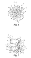
- a spinal column segment 10 including an upper vertebra V U , a lower vertebra V L and a spinal disc 13 therebetween along a central axis 11 of the spinal column.
- the vertebrae V U , V L and disc 13 comprise a spinal motion segment, it being understood that a spinal motion segment may include multiple vertebral levels in one more of the lumbar, thoracic, and cervical regions of the spine.
- Upper vertebra V U includes an upper spinous process SP 1 while the lower vertebra V L includes a lower spinous process SP 2 , with the spinous processes SP 1 , SP 2 defining a space S therebetween.
- the spinous processes SP 1 and SP 2 comprise posterior elements of the vertebrae V U , V L of the spinal motion segment along with the transverse processes 15, 16, 17, and 18, laminae 19a, 19b, facets, pedicles and other posterior structures of each vertebrae V U , V L .
- a spinal implant 30 in the form of a spacer member 31 is positioned in the space S and extends between and engages with the spinous processes SP 1 , SP 2 to provide stabilization and modification of the spinal motion segment.
- Spacer member 31 includes a body 32 which in its implanted orientation has a first lateral side 34 and a second lateral side 36, with the lateral sides 34, 36 extending between a superior end 38 and an inferior end 40. As best seen in FIG. 2 , for example, the body also includes an anterior side 42 opposite a posterior side 44.
- each of the anterior and posterior sides 42, 44, lateral sides 34, 36, and superior and inferior ends 38, 40 may be rounded or beveled in order to decrease the profile of the body 32 and minimize intrusion and potential trauma to adjacent neural tissue and surrounding spinal anatomy.
- the body 32 further includes a first concave portion 46 and a second concave portion 48 situated at respective superior and inferior ends 38, 40.
- Each of the concave portions 46, 48 is disposed between a pair of respective upright arms 50a, 50b and 52a, 52b.
- Concave portions 46, 48 are sized and shaped to engage with and receive respective inferior surface 12 of the upper spinous process SP 1 and superior surface 14 of the lower spinous process SP 2 .
- the arms 50a, 50b, 52a, and 52b extend beyond the respective concave portions 46, 48 to engage with the lateral sides of the spinous processes SP 1 , SP 2 .
- concave portions 46, 48 are illustrated having a substantially arcuate shape, it should be appreciated that in one or more forms the concave portions 46, 48 may include an alternative configuration, such as a rectangular shape or may be structured to receive a greater portion of the spinous processes SP 1 , SP 2 to further resist dislodgement from space S.
- the upper vertebra V U and lower vertebra V L have a normal center of rotation COR N (illustrated in phantom) for flexion and extension motion of the spinal motion segment when the spacer member 31 is not positioned in space S between the spinous processes SP 1 , SP 2 .
- the normal center of rotation CORN is located substantially in the center of the vertebral bodies VB 1 , VB 2 in Fig. 2 , it should be appreciated that the position of the normal center of rotation CORN may vary based on several factors, including the region of the spinal column, individual patient anatomy, disease state or the effects of concurrent procedures (such as spinal decompression), just to name a few. Also illustrated in Fig.
- the spacer member includes a first section 54 adjacent to anterior side 42 and a second section 56 positioned adjacent to posterior side 44 and abutting against first section 54, with each of the sections 54, 56 extending longitudinally between the spinous processes SP 1 , SP 2 .
- a portion of first section 54 is surrounded, at least along its superior and inferior sides, with second section 56.
- First and second sections 54, 56 form an overlapping arrangement in the anterior-posterior directions that provides a transition in the stiffness profile where the stiffness decrease posteriorly.
- First section 54 includes a posterior portion 55 that extends part-way into second section 56 in the anterior to posterior direction.
- the spacer member 31 is fabricated from components that are flexible or exhibit at least some flexibility with the second section 56 being more flexible than the first section 54. Additionally, at least a portion of the spacer member 31 is resilient and/or elastic so it can assume various shapes during and after insertion and attachment. The materials for the first section 54 and the second section 56 are selected based upon their modulus of elasticity.
- sections 54, 56 may comprise any biocompatible material, material of synthetic or natural origin, and material of a resorbable or non-resorbable nature so long as the flexibility of the sections varies.
- section 54 comprises PEEK while section 56 comprises silicone.
- other polymers such as ultra-high molecular weight polyethylene, polyaryletherketone, polyacetal, polysulfone, polyimide, polyester, polyvinyl alcohol, polyacrylonitrile, polytetrafluorethylene, poly-paraphenylene, terephthalamide, cellulose, biocompatible rubber materials, and combinations thereof may be used.
- Suitable ceramic materials may include alumina, zirconia, polycrystalline diamond compact, pyrolitic carbon, and porous tantalum material.
- Suitable composite materials may include carbon-filled composites, hydroxyl-appetite-filled composites, and bioactive-glass-filled composites.
- the spacer member 31 may also include autograft, allograft or xenograft material and tissue materials including soft tissues, connective tissues, demineralized bone matrix and combinations thereof.
- any one or more of polylactide, polyglycolide, tyrosine-derived polycarbonate, polyanhydride, polyorthoester, polyphosphazene, calcium phosphate, hydroxyapatite, bioactive glass, collagen, albumin, fibrinogen and combinations thereof may be a suitable material. It should be appreciated that the selection of material for one or both of sections 54, 56 will influence the positioning of the centers of rotation for flexion and extension COR F , COR E .
- each of the spinous processes SP 1 , SP 2 bears against the first section 54 and the more flexible second section 56. Since the spinous processes bear against both sections 54 and 56, a preferential deformation of the spacer member 31 is formed by movement of the spinal motion segment and the centers of rotation for flexion and extension COR F , CORE are influenced.
- the center of rotation for extension CORE is moved posterior to the normal center of rotation CORN because the spinous processes SP 1 , SP 2 rotate about the more rigid section 54 and compress or deform the more flexible second section 56 as they move toward one another.
- the spinous processes SP 1 , SP 2 again rotate about the more rigid section 54 until enough force is created to compress or deform section 54, thus repositioning the center of rotation for flexion COR F anterior to the normal center of rotation CORN.
- section 54 is provided with sufficient rigidity in one embodiment to maintain a distraction distance between the laminae 19a, 19b in order to avoid stenosis and associated neural complications.
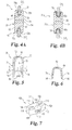
- each of Figs. 3B-3G there is illustrated a sectional view of alternative spacer members 31b-31g. Only the spacer members of figures 3A, 3C and 3D fall within the scope of the claims. It should be understood that the configuration of each of the spacer members 31 a-31 g has been varied by adjusting the positioning of the first section 54 relative to the second section 56 in order to provide spacer members with alternative flexibility characteristics which may be used to alternatively vary or control movement of the spinal motion segment.
- spacer member 31b further includes a third section 58 which comprises a material generally more flexible than the material of sections 54, 56.
- the material of section 58 is generally structured to conform to the respective adjacent spinous process SP 1 or SP 2 in order to provide enhanced reception and engagement and may comprise one or more of the materials suitable for sections 54 and 56.
- the spacer members 31c and 31d will react much the same as spacer 31 during flexion and extension.
- first section 54 and second section 56 are arranged in side-by-side relation to one another in the anterior-posterior direction with no overlapping portions.
- first section 54 includes a posterior extension 55 that is surrounded at least one its superior and inferior sides with second section 56, and extension 55 extends to the posterior side 44.
- first section 54 is disposed both superiorly and inferiorly around the second section 56, such that the first section 54 creates an axial force which compresses the second section 56 during extension of the spinal motion segment.
- first section 54 of spacer member 31f is at least partially surrounded by the second section 56 such that the first section 54 will limit the flexibility of the second section 56 when a force greater than the elastic or compressive limit of section 56 is applied thereto.
- first section 54 is surrounded at least partially along its anterior and posterior sides with a more flexible second section 56. Spacer 31 g will provide deformation of the second section 56 during both spinal extension and spinal flexion, while first section 54 provides resistance to deformation when the supported vertebrae are in their neutral position.
- first and second sections contemplate more than first and second sections to provide additional gradations in the flexibility of the implant.
- one of the first and second sections may be removable from the spacer member and replaced with an alternative replacement section in order to alter the flexibility characteristics of the spacer member.
- second section 56 may be removable from the spacer member 31.
- a plurality of replacement sections having flexibility characteristics different from the first section 54 and the second section 56 may be provided to replace the second section 56.
- both the second section 56 and the replacement sections may be engaged with the spacer member 31 and the first section 54 through any standard manner, including a friction fit, pinning, tacking, stapling, screwing and/or any combination thereof, just to name a few possibilities.
- the stabilization of the spinal motion segment may be monitored subsequent to positioning the spacer member 31 between the spinous processes SP 1 , SP 2 to determine if alterations to the stabilization are desired. For example, it may be desired to adjust the positioning of one or both of the centers of rotation for flexion and extension COR F , COR E .
- the removable section may be replaced with one of the replacement sections having different flexibility characteristics.
- the flexibility of the selected replacement section may be less than that of the second section 56 but greater than that of the first section 54.
- the stabilization of the spinal motion segment may be continually monitored and that the removable one of the first and second sections may be replaced with one of the replacement sections until the desired stabilization is achieved.
- the procedure of removing the removable section and replacing it with the alternative section may be performed through any standard surgical procedure. However, in one form, in order to minimize surgical complexity and trauma to the patient, it is contemplated that the procedure is performed percutaneously through a minimally invasive procedure.
- FIG. 4A a sectional view of respective spacer members 31 and 31b along line 4-4 of Fig. 2 .
- the portion of the body 32 of spacer member 31 which forms arms 50a, 50b, 52a, and 52b engages with the upper and lower spinous processes SP 1 , SP 2 .
- this portion of the body 32 may be flexible enough to at least partially conform to the spinous processes SP 1 , SP 2 .
- the third section 58 is disposed around the concave portions 46b, 48b to provide a surface that conforms to the spinous processes SP 1 , SP 2 regardless of the flexibility or rigidity of the rest of the body 32b.
- the spacer members of figures 4A, 4B, 5 and 6 do not fall within the scope of the claims.
- the spacer member 71 includes a substantially U-shaped body 73 including longitudinal members 75 and 76 and an arcuate portion 82 extending between the longitudinal members 75, 76 to form a concave area 84 extending between surfaces 78 and 80.
- the body 72 is structured for positioning in the space S between the upper and lower spinous processes SP 1 , SP 2 such that the concave area 84 faces in an anterior direction with the upright members 75, 76 abutting a posterior surface of the laminae 19a, 19b and the upper spinous process SP 1 engaging with surface 78 and the lower spinous process SP 2 engaging ith surface 80.
- the body 72 may be structured so that the longitudinal members 75, 76 may be positioned between the adjacent laminae 19a, 19b to keep a distraction space between the laminae 19a, 19b while the surfaces 78, 80 engage with and support the adjacent spinous processes SP 1 , SP 2 .
- the body 72 may include one or more features structured to resist anterior migration of the implant 70 into the spinal canal.
- surfaces 78, 80 may include a recessed area for receiving and engaging the spinous process SP 1 , SP 2 .
- spacer member 71 includes a first section 86 disposed generally in the longitudinal members 75, 76 and a second section 88 disposed generally in the arcuate portion 82.
- the spacer member 71 can be fabricated from components that are flexible or exhibit at least some flexibility with the second section 88 being more flexible than the first section 86.
- the flexibility of the sections 86, 88 may be varied by using materials with different elastic, flexibility, or rigidity qualities.
- one or more of the materials comprising sections 86, 88 may be selected from the materials set forth herein above in regard to spacer member 31.
- the more rigid first section 86 is positioned anterior to the more flexible second section 88 and the centers of rotation for flexion and extension COR F , CORE will be repositioned relative to the normal center of rotation CORN as described above in regard to spacer member 31.
- the spacer member 71 will maintain a distraction distance between the laminae 19a, 19b to help avoid stenosis and associated neural complications.
- alternative section views of spacer member 71 have not been provided, it is contemplated that the configuration and positioning of the first section 86 and the second section 88 may be modified in order to provide a spacer member 71 with various flexibility and stabilization features.
- Spacer member 101 is generally similar to spacer member 31 and includes a body 102 which in an implantation orientation extends between a superior end 104 and an inferior end 106.
- the body 102 also generally includes lateral sides 108, 110 and anterior side 112 and posterior side 114.
- the concave portions 116, 118 are structured to engage with and receive the upper and lower spinous processes SP 1 , SP 2 as described herein.
- the body includes a first section 120 positioned anterior to a hollow chamber 122 with the chamber 122 being structured to receive one or more injectable materials.
- the body 102 When the chamber 122 includes the injectable material, the body 102 includes a second section in addition to the first section 120.
- the injectable material may include gels, pastes, slurries, or liquids, just to name a few possibilities.
- the injectable material may be deliverable in a first state and cure to a second state after injection.
- the injectable material will be more flexible than the first section 120 in order to provide an implant with flexibility and stabilization features similar to that of spacer member 31.
- the body 102 may include one or more injection ports to receive the injectable material from a delivery instrument.
- the body 102 may include one or more chambers in addition to chamber 122. It should also be appreciated that the positioning of the one or more chambers 122 or first section 120 may be altered to provide spacer members with various flexibility and stabilization features.
- the injectable material may be removed from the chamber 122 subsequent to positioning of the spacer member 101 at an implantation location.
- a patient may be monitored to determine if changes to the stabilization of the spinal motion segment are necessary. For example, after the initial positioning of the spacer member 101, it may be determined that one or both of the centers of rotation for flexion and extension COR F , COR E needs to be adjusted. If an adjustment is necessary, the injectable material may be removed and replaced with an alternative injectable material having different flexibility characteristics in order to alter one or both of the centers of rotation for flexion and extension COR F , CORE as desired.
- the stabilization of the spinal motion segment may be continuously monitored and, if necessary, the injectable material may be varied until desired stabilization of the spinal motion segment is accomplished.
- the injectable material may be removed and introduced to the chamber 122 of the spacer member 101 through any known surgical procedure.
- the spacer member 101 is structured for access by a delivery instrument through a percutaneous surgical procedure in a minimally invasive manner in order to minimize surgical complexity and trauma to the patient.
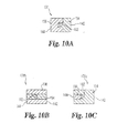
- Implant assembly 125 includes a spinal implant 130 in the form of a spacer member 131 positioned in the space S and extending between and engaging with the spinous processes SP 1 , SP 2 to provide stabilization and modification of the spinal motion segment.
- Spacer member 131 includes a body 132 which in its implanted orientation has a first lateral side 134 and a second lateral side 136, with the lateral sides 134, 136 extending between a superior end 138 and an inferior end 140.
- the body also includes an anterior side 142 opposite a posterior side 144.
- each of the anterior and posterior sides 142, 144, lateral sides 134, 136, and superior and inferior ends 138, 140 may be rounded or beveled in order to decrease the profile of the body 132 and minimize intrusion and the potential for trauma to adjacent neural tissue and surrounding spinal anatomy.
- the body 132 further includes a first concave portion 146 and a second concave portion 148 situated at respective superior and inferior ends 138, 140.
- Each of the concave portions 146, 148 is disposed between a pair of respective upright arms 150a, 150b and 152a, 152b.
- Concave portions 146, 148 are sized and shaped to engage with and receive respective inferior surface 12 of the upper spinous process SP 1 and superior surface 14 of the lower spinous process SP 2 .
- the arms 150a, 150b, 152a, and 152b extend beyond the respective concave portion 146 and concave portion 148 to engage with the lateral sides of the spinous processes SP 1 , SP 2 to prevent or resist dislodgement of the spacer member 131 from space S.
- Spacer member 131 is similar to spacer member 31 discussed above but also includes an engaging member 160 extending therefrom to attach spacer member 131 to posterior vertebral elements or implants of the spinal motion segment.
- Spacer member 131 includes any arrangement for spacer member 31 discussed above in Figs. 1-3G .
- Spacer member 131 includes through-passages 162 extending between opposite sides thereof, which include the lateral sides 134, 136 of spacer member 131 in the illustrated embodiment. Passages 162 receive engaging member 160 therethrough.
- Engaging member 160 may comprise multiple engaging members, or a single engaging member looped through passages 162. Still other embodiments contemplate a single passage 162, or three or more passages 162, through which one or more engaging members 160 are positioned.
- spacer member 131 is similar to spacer member 31 and likewise includes a first section 154 and a more flexible second portion 156. Sections 154, 156 are also similar to sections 54, 56 described above in regard to spacer 31. However, the first section 154 includes passages 162 extending therethrough. When the engaging member 160 is received in passages 162 and is engaged to posterior vertebral elements or other implants and an axial pulling force is exerted on the spacer member 131, the more rigid section 154 resists deformation of the spacer body. Moreover, alternative spacer members 131b and 131c are illustrated in section view in Figs.
- the passages extend through the more rigid section 154 such that as an axial pulling force is exerted on the spacer member 131b, the more rigid section 154 again resists deformation of the spacer member 131b.
- the passages 162 extend through the more flexible second section 156 which is situated between superior and inferior portions of first section 154. In this form, the second section 156 is deformable in response to the axial pulling force until it is limited by the surrounding more rigid first section 154.
- the engaging member 160 and the passages 162 may be alternatively configured relative to the first and second sections 154, 156 in accordance with the various embodiments set forth herein.
- Engaging member 160 can be in the form of a tether, cord, wire, cable, suture, band, strap, belt, or other suitable structure for manipulation and securement to one or more posterior vertebral elements. Engaging member 160 may be wrapped or positioned around posterior vertebral elements and then maintained in position with a crimp or other suitable fastener. Furthermore, engaging member 160 can be coupled to spacer member 131 in any suitable manner. In one embodiment, engaging member 160 is movably coupled to spacer member 131. Engaging member 160 can be integrally formed with spacer member 131, or can be attached by a fastener, suture, anchor, cable, link, over-molding or other suitable connection.
- Spacer member 131 can be provided with ears, eyelets, recesses or other suitable structure to facilitate engagement of engaging member 160 to spacer member 131.
- Engaging member 160 may be employed in spinal stabilization procedures where it is desired to limit spinal flexion by, for example, wrapping engaging member 160 about the superior surface of the upper spinous process and/or upper lamina and the inferior surface of the lower spinous process and/or the lower lamina.
- Engaging member may alternatively be employed as a retention mechanism to maintain spacer member 160 in position between the spinous processes.
- the engaging member can be joined or fixed to the spacer member using various devices and/or techniques, or can be integrally formed with or form an extension of the spacer member.
- the spacer member can be joined or attached to the engaging member by, for example, sewing the engaging member to the spacer member, thermal welding or bonding, adhesive bonding, three dimensional weaving or braiding, screws, staples, pins, tacks or rivet fixation.
- the engaging member can be secured to the spacer member either before or after the spacing member is placed between the spinous processes.
- the engaging member can be engaged to other engaging members of other implant assemblies or to other implants engaged to the spinal column in the surgical procedure.
- the engaging members described herein can be made from any one or combinations of biocompatible material, including synthetic or natural autograft, allograft or xenograft tissues, and can be resorbable or non-resorbable nature.
- tissue materials include hard tissues, connective tissues, demineralized bone matrix and combinations thereof.
- resorbable materials are polylactide, polyglycolide, tyrosine-derived polycarbonate, polyanhydride, polyorthoester, polyphosphazene, calcium phosphate, hydroxyapatite, bioactive glass, and combinations thereof.
- Further examples of non-resorbable materials are carbon-reinforced polymer composites, shape-memory alloys, titanium, titanium alloys, cobalt chrome alloys, stainless steel, and combinations thereof.
- one or more of the spacers contemplated herein may include one or more additional sections with one more additional elasticity, flexibility, or rigidity qualities.
- the spacer member may not include one of the first or second sections.
- a plurality of coupleable members sized and shaped like the first or second section may be provided with differing flexibility characteristics so that a surgeon may select which to include at the implant site during a surgical procedure.
- the coupleable members may engage with the spacer members through any one or more of a press fit engagement, a mechanical connection, fusion, or adhesion, just to name a few possibilities.
- the spacer members may be integrally formed or may include one or more portions coupled together.
- stiffening members can be provided to enhance or increase the stiffness of spacer members 31, 71, 101, 131.
- a stiffening member may be in the form of a band that extends about and contacts the perimeter of spacer members 31, 71, 101, 131.
- more than one stiffening member can be provided about spacer members 31, 71, 101, 131 to allow the stiffness profile of the spacer members 31, 71, 101, 131 to be increased or decreased by adding or removing a stiffening member.
- stiffening members include woven fabric tubing, woven and non-woven mesh, or braided or woven structures, sutures, tethers, cords, planar members, bands, wires, cables, or any other component capable of extending about the perimeter of the spacer member to increase stiffness thereof.
Landscapes
- Health & Medical Sciences (AREA)
- Orthopedic Medicine & Surgery (AREA)
- Life Sciences & Earth Sciences (AREA)
- Neurology (AREA)
- Surgery (AREA)
- Heart & Thoracic Surgery (AREA)
- Engineering & Computer Science (AREA)
- Biomedical Technology (AREA)
- Nuclear Medicine, Radiotherapy & Molecular Imaging (AREA)
- Medical Informatics (AREA)
- Molecular Biology (AREA)
- Animal Behavior & Ethology (AREA)
- General Health & Medical Sciences (AREA)
- Public Health (AREA)
- Veterinary Medicine (AREA)
- Prostheses (AREA)
Applications Claiming Priority (2)
| Application Number | Priority Date | Filing Date | Title |
|---|---|---|---|
| US12/050,274 US8114136B2 (en) | 2008-03-18 | 2008-03-18 | Implants and methods for inter-spinous process dynamic stabilization of a spinal motion segment |
| PCT/US2009/034208 WO2009117198A1 (en) | 2008-03-18 | 2009-02-16 | Implants and methods for inter-spinous process dynamic stabilization of a spinal motion segment |
Publications (2)
| Publication Number | Publication Date |
|---|---|
| EP2278932A1 EP2278932A1 (en) | 2011-02-02 |
| EP2278932B1 true EP2278932B1 (en) | 2014-08-13 |
Family
ID=40482052
Family Applications (1)
| Application Number | Title | Priority Date | Filing Date |
|---|---|---|---|
| EP09722726.8A Active EP2278932B1 (en) | 2008-03-18 | 2009-02-16 | Implants for inter-spinous process dynamic stabilization of a spinal motion segment |
Country Status (4)
| Country | Link |
|---|---|
| US (2) | US8114136B2 (enExample) |
| EP (1) | EP2278932B1 (enExample) |
| JP (1) | JP2011515148A (enExample) |
| WO (1) | WO2009117198A1 (enExample) |
Families Citing this family (58)
| Publication number | Priority date | Publication date | Assignee | Title |
|---|---|---|---|---|
| US6068630A (en) | 1997-01-02 | 2000-05-30 | St. Francis Medical Technologies, Inc. | Spine distraction implant |
| US20080039859A1 (en) | 1997-01-02 | 2008-02-14 | Zucherman James F | Spine distraction implant and method |
| US7959652B2 (en) * | 2005-04-18 | 2011-06-14 | Kyphon Sarl | Interspinous process implant having deployable wings and method of implantation |
| US20080086212A1 (en) | 1997-01-02 | 2008-04-10 | St. Francis Medical Technologies, Inc. | Spine distraction implant |
| US8221463B2 (en) | 2002-10-29 | 2012-07-17 | Kyphon Sarl | Interspinous process implants and methods of use |
| US8048117B2 (en) | 2003-05-22 | 2011-11-01 | Kyphon Sarl | Interspinous process implant and method of implantation |
| US8147548B2 (en) | 2005-03-21 | 2012-04-03 | Kyphon Sarl | Interspinous process implant having a thread-shaped wing and method of implantation |
| US7549999B2 (en) | 2003-05-22 | 2009-06-23 | Kyphon Sarl | Interspinous process distraction implant and method of implantation |
| US8241330B2 (en) | 2007-01-11 | 2012-08-14 | Lanx, Inc. | Spinous process implants and associated methods |
| US9055981B2 (en) | 2004-10-25 | 2015-06-16 | Lanx, Inc. | Spinal implants and methods |
| US8096994B2 (en) | 2005-02-17 | 2012-01-17 | Kyphon Sarl | Percutaneous spinal implants and methods |
| US8100943B2 (en) | 2005-02-17 | 2012-01-24 | Kyphon Sarl | Percutaneous spinal implants and methods |
| US8157841B2 (en) | 2005-02-17 | 2012-04-17 | Kyphon Sarl | Percutaneous spinal implants and methods |
| US8034080B2 (en) | 2005-02-17 | 2011-10-11 | Kyphon Sarl | Percutaneous spinal implants and methods |
| US8097018B2 (en) | 2005-02-17 | 2012-01-17 | Kyphon Sarl | Percutaneous spinal implants and methods |
| US8038698B2 (en) | 2005-02-17 | 2011-10-18 | Kphon Sarl | Percutaneous spinal implants and methods |
| US8007521B2 (en) | 2005-02-17 | 2011-08-30 | Kyphon Sarl | Percutaneous spinal implants and methods |
| US8029567B2 (en) | 2005-02-17 | 2011-10-04 | Kyphon Sarl | Percutaneous spinal implants and methods |
| US20070276493A1 (en) | 2005-02-17 | 2007-11-29 | Malandain Hugues F | Percutaneous spinal implants and methods |
| US8029549B2 (en) * | 2005-02-17 | 2011-10-04 | Kyphon Sarl | Percutaneous spinal implants and methods |
| US8096995B2 (en) | 2005-02-17 | 2012-01-17 | Kyphon Sarl | Percutaneous spinal implants and methods |
| US8066742B2 (en) | 2005-03-31 | 2011-11-29 | Warsaw Orthopedic, Inc. | Intervertebral prosthetic device for spinal stabilization and method of implanting same |
| US8034079B2 (en) | 2005-04-12 | 2011-10-11 | Warsaw Orthopedic, Inc. | Implants and methods for posterior dynamic stabilization of a spinal motion segment |
| US7727233B2 (en) | 2005-04-29 | 2010-06-01 | Warsaw Orthopedic, Inc. | Spinous process stabilization devices and methods |
| US8083795B2 (en) | 2006-01-18 | 2011-12-27 | Warsaw Orthopedic, Inc. | Intervertebral prosthetic device for spinal stabilization and method of manufacturing same |
| US8262698B2 (en) | 2006-03-16 | 2012-09-11 | Warsaw Orthopedic, Inc. | Expandable device for insertion between anatomical structures and a procedure utilizing same |
| US8118844B2 (en) | 2006-04-24 | 2012-02-21 | Warsaw Orthopedic, Inc. | Expandable device for insertion between anatomical structures and a procedure utilizing same |
| US8105357B2 (en) | 2006-04-28 | 2012-01-31 | Warsaw Orthopedic, Inc. | Interspinous process brace |
| US8252031B2 (en) | 2006-04-28 | 2012-08-28 | Warsaw Orthopedic, Inc. | Molding device for an expandable interspinous process implant |
| US8048118B2 (en) | 2006-04-28 | 2011-11-01 | Warsaw Orthopedic, Inc. | Adjustable interspinous process brace |
| US20070270823A1 (en) | 2006-04-28 | 2007-11-22 | Sdgi Holdings, Inc. | Multi-chamber expandable interspinous process brace |
| US8062337B2 (en) | 2006-05-04 | 2011-11-22 | Warsaw Orthopedic, Inc. | Expandable device for insertion between anatomical structures and a procedure utilizing same |
| US8048119B2 (en) | 2006-07-20 | 2011-11-01 | Warsaw Orthopedic, Inc. | Apparatus for insertion between anatomical structures and a procedure utilizing same |
| US8097019B2 (en) | 2006-10-24 | 2012-01-17 | Kyphon Sarl | Systems and methods for in situ assembly of an interspinous process distraction implant |
| FR2908035B1 (fr) | 2006-11-08 | 2009-05-01 | Jean Taylor | Implant interepineux |
| US9265532B2 (en) | 2007-01-11 | 2016-02-23 | Lanx, Inc. | Interspinous implants and methods |
| WO2008106140A2 (en) | 2007-02-26 | 2008-09-04 | Abdou M Samy | Spinal stabilization systems and methods of use |
| US8840646B2 (en) * | 2007-05-10 | 2014-09-23 | Warsaw Orthopedic, Inc. | Spinous process implants and methods |
| US20110172708A1 (en) * | 2007-06-22 | 2011-07-14 | Simpirica Spine, Inc. | Methods and systems for increasing the bending stiffness of a spinal segment with elongation limit |
| US20090198338A1 (en) | 2008-02-04 | 2009-08-06 | Phan Christopher U | Medical implants and methods |
| US8114136B2 (en) | 2008-03-18 | 2012-02-14 | Warsaw Orthopedic, Inc. | Implants and methods for inter-spinous process dynamic stabilization of a spinal motion segment |
| US20100012068A1 (en) * | 2008-07-03 | 2010-01-21 | International Engine Intellectual Property Company , Llc | Prioritizing Use Of Engine Cold Start Aids To mitigate Effect Of Weakened Battery Bank |
| US8114131B2 (en) | 2008-11-05 | 2012-02-14 | Kyphon Sarl | Extension limiting devices and methods of use for the spine |
| CN102448392A (zh) | 2009-03-31 | 2012-05-09 | 兰克斯股份有限公司 | 棘突植入物及相关方法 |
| US8372117B2 (en) | 2009-06-05 | 2013-02-12 | Kyphon Sarl | Multi-level interspinous implants and methods of use |
| EP2475334A4 (en) * | 2009-09-11 | 2014-10-22 | Articulinx Inc | DISK ORTHOPEDIC DEVICES |
| US8114132B2 (en) | 2010-01-13 | 2012-02-14 | Kyphon Sarl | Dynamic interspinous process device |
| US8317831B2 (en) | 2010-01-13 | 2012-11-27 | Kyphon Sarl | Interspinous process spacer diagnostic balloon catheter and methods of use |
| US8147526B2 (en) | 2010-02-26 | 2012-04-03 | Kyphon Sarl | Interspinous process spacer diagnostic parallel balloon catheter and methods of use |
| US8591548B2 (en) | 2011-03-31 | 2013-11-26 | Warsaw Orthopedic, Inc. | Spinous process fusion plate assembly |
| US8591549B2 (en) * | 2011-04-08 | 2013-11-26 | Warsaw Orthopedic, Inc. | Variable durometer lumbar-sacral implant |
| US20120323276A1 (en) | 2011-06-17 | 2012-12-20 | Bryan Okamoto | Expandable interspinous device |
| US9149306B2 (en) | 2011-06-21 | 2015-10-06 | Seaspine, Inc. | Spinous process device |
| US11812923B2 (en) | 2011-10-07 | 2023-11-14 | Alan Villavicencio | Spinal fixation device |
| US9259249B2 (en) * | 2013-11-26 | 2016-02-16 | Globus Medical, Inc. | Spinous process fixation system and methods thereof |
| CN103705296A (zh) * | 2014-01-17 | 2014-04-09 | 李照文 | 棘板间万向动态稳定器 |
| US10335207B2 (en) | 2015-12-29 | 2019-07-02 | Nuvasive, Inc. | Spinous process plate fixation assembly |
| US11723694B2 (en) | 2021-03-31 | 2023-08-15 | Bret Michael Berry | Adjustable spinous process implant |
Citations (2)
| Publication number | Priority date | Publication date | Assignee | Title |
|---|---|---|---|---|
| WO2006086241A2 (en) * | 2005-02-04 | 2006-08-17 | Nuvasive, Inc. | Methods and apparatus for treating spinal stenosis |
| US20070112350A1 (en) * | 2003-10-24 | 2007-05-17 | Guy Deneuvillers | Inter-laminar support |
Family Cites Families (441)
| Publication number | Priority date | Publication date | Assignee | Title |
|---|---|---|---|---|
| US624969A (en) | 1899-05-16 | Peter peterson | ||
| US1153797A (en) | 1915-04-29 | 1915-09-14 | Jules Emile Kegreisz | Expansion-anchor. |
| US1516347A (en) | 1923-08-30 | 1924-11-18 | Pataky Anton | Coupling pin |
| US1870942A (en) | 1928-05-26 | 1932-08-09 | Gynex Corp | Syringe |
| US2077804A (en) | 1936-05-19 | 1937-04-20 | Morrison Gordon Monroe | Device for treating fractures of the neck of the femur |
| US2299308A (en) | 1941-08-15 | 1942-10-20 | Russell A Creighton | Self-locking spike |
| US2485531A (en) | 1948-01-13 | 1949-10-18 | Dzus William | Surgical toggle bolt |
| US2607370A (en) | 1948-07-13 | 1952-08-19 | Oscar F Anderson | Pipe plug |
| US2685877A (en) | 1952-03-20 | 1954-08-10 | Dobelle Martin | Femoral head prosthesis |
| US2677369A (en) | 1952-03-26 | 1954-05-04 | Fred L Knowles | Apparatus for treatment of the spinal column |
| US2774350A (en) | 1952-09-08 | 1956-12-18 | Jr Carl S Cleveland | Spinal clamp or splint |
| US3065659A (en) | 1959-09-28 | 1962-11-27 | Superior Concrete Accessories | Expansion bolt |
| US3108595A (en) | 1960-08-08 | 1963-10-29 | Alfred P Overment | Retention catheter |
| US3397699A (en) | 1966-05-05 | 1968-08-20 | Gerald C. Kohl | Retaining catheter having resiliently biased wing flanges |
| US3426364A (en) | 1966-08-25 | 1969-02-11 | Colorado State Univ Research F | Prosthetic appliance for replacing one or more natural vertebrae |
| US3648691A (en) | 1970-02-24 | 1972-03-14 | Univ Colorado State Res Found | Method of applying vertebral appliance |
| US3693616A (en) | 1970-06-26 | 1972-09-26 | Robert Roaf | Device for correcting scoliotic curves |
| DE2112139B2 (de) | 1971-03-13 | 1973-02-01 | Fischer, Artur, 7241 Tumhngen | Huelsenfoermiges verbindungselement fuer die kompressions-osteosynthese bei roehrenknochenfrakturen |
| US4011602A (en) | 1975-10-06 | 1977-03-15 | Battelle Memorial Institute | Porous expandable device for attachment to bone tissue |
| US4704057A (en) | 1976-09-15 | 1987-11-03 | Mechanical Plastics Corp. | Fastening element |
| PL114098B1 (en) | 1978-04-14 | 1981-01-31 | Wyzsza Szkola Inzynierska | Apparatus for correcting spinal curvature |
| US4274324A (en) | 1978-04-18 | 1981-06-23 | Giannuzzi Louis | Hollow wall screw anchor |
| CH628803A5 (en) | 1978-05-12 | 1982-03-31 | Sulzer Ag | Implant insertable between adjacent vertebrae |
| US4237875A (en) | 1979-02-23 | 1980-12-09 | Towmotor Corporation | Dynamic intramedullary compression nailing |
| US4327736A (en) | 1979-11-20 | 1982-05-04 | Kanji Inoue | Balloon catheter |
| US4289123A (en) | 1980-03-31 | 1981-09-15 | Dunn Harold K | Orthopedic appliance |
| GB2083754B (en) | 1980-09-15 | 1984-04-26 | Rezaian Seyed Mahmoud | Spinal fixator |
| SU988281A1 (ru) | 1981-06-26 | 1983-01-15 | За витель | Устройство дл фиксации позвоночника |
| US4646998A (en) | 1981-11-20 | 1987-03-03 | Clairson International Corporation | Wall-mounted shelf support clip |
| DE3235974A1 (de) | 1981-11-24 | 1983-06-01 | Volkmar Dipl.-Ing. Merkel (FH), 8520 Erlangen | Vorrichtung zur entfernung bzw. zur aufweitung von engstellen in koerperfluessigkeit fuehrenden gefaessen |
| US4422451A (en) | 1982-03-22 | 1983-12-27 | Ali Kalamchi | Spinal compression and distraction instrumentation |
| US4519100A (en) | 1982-09-30 | 1985-05-28 | Orthopedic Equipment Co. Inc. | Distal locking intramedullary nail |
| US4499636A (en) | 1983-05-06 | 1985-02-19 | Nifco Inc. | Removable two-piece retaining means |
| US4822226A (en) | 1983-08-08 | 1989-04-18 | Kennedy Arvest G | Wing nut retainer and extractor |
| US4554914A (en) | 1983-10-04 | 1985-11-26 | Kapp John P | Prosthetic vertebral body |
| US4553273A (en) | 1983-11-23 | 1985-11-19 | Henry Ford Hospital | Vertebral body prosthesis and spine stabilizing method |
| GB8333442D0 (en) | 1983-12-15 | 1984-01-25 | Showell A W Sugicraft Ltd | Devices for spinal fixation |
| US4611582A (en) | 1983-12-27 | 1986-09-16 | Wisconsin Alumni Research Foundation | Vertebral clamp |
| US4604995A (en) | 1984-03-30 | 1986-08-12 | Stephens David C | Spinal stabilizer |
| US4573454A (en) | 1984-05-17 | 1986-03-04 | Hoffman Gregory A | Spinal fixation apparatus |
| JPS60187737U (ja) | 1984-05-23 | 1985-12-12 | オリンパス光学工業株式会社 | 留置チユ−ブガイド装置 |
| FR2575059B1 (fr) | 1984-12-21 | 1988-11-10 | Daher Youssef | Dispositif d'etaiement utilisable dans une prothese vertebrale |
| US4632101A (en) | 1985-01-31 | 1986-12-30 | Yosef Freedland | Orthopedic fastener |
| US4721103A (en) | 1985-01-31 | 1988-01-26 | Yosef Freedland | Orthopedic device |
| US4636217A (en) | 1985-04-23 | 1987-01-13 | Regents Of The University Of Minnesota | Anterior spinal implant |
| US4599086A (en) | 1985-06-07 | 1986-07-08 | Doty James R | Spine stabilization device and method |
| SE458417B (sv) | 1985-08-15 | 1989-04-03 | Sven Olerud | Fixationsinstrument avsett foer anvaendning vid ryggoperationer |
| US4662808A (en) | 1985-10-02 | 1987-05-05 | Lee-Rowan Company | Wall anchor |
| US5112306A (en) | 1986-03-25 | 1992-05-12 | American Medical Systems, Inc. | Method and apparatus for valving body fluids |
| WO1987007134A1 (en) | 1986-05-30 | 1987-12-03 | John Bumpus | Distraction rods |
| GB8620937D0 (en) | 1986-08-29 | 1986-10-08 | Shepperd J A N | Spinal implant |
| US4969887A (en) | 1986-09-08 | 1990-11-13 | Sodhi Jitendra S | Self-retaining nail kit for repairing a fractured neck of femur |
| US4787378A (en) | 1986-09-08 | 1988-11-29 | Sodhi Jitendra S | Self-retaining nail for fracture of neck of femur |
| CA1283501C (en) | 1987-02-12 | 1991-04-30 | Thomas P. Hedman | Artificial spinal disc |
| SU1484348A1 (ru) | 1987-03-04 | 1989-06-07 | Белорусский научно-исследовательский институт травматологии и ортопедии | Фиксатор позвоночника |
| US4913134A (en) | 1987-07-24 | 1990-04-03 | Biotechnology, Inc. | Spinal fixation system |
| FR2623085B1 (fr) | 1987-11-16 | 1992-08-14 | Breard Francis | Implant chirurgical pour limiter le mouvement relatif des vertebres |
| FR2625097B1 (fr) | 1987-12-23 | 1990-05-18 | Cote Sarl | Prothese inter-epineuse composee dans une matiere semi-elastique et comportant un oeillet de transfilage a son extremite et de coussinets inter-epineux |
| CH674709A5 (enExample) | 1988-04-27 | 1990-07-13 | Sulzer Ag | |
| US5609635A (en) | 1988-06-28 | 1997-03-11 | Michelson; Gary K. | Lordotic interbody spinal fusion implants |
| US4892545A (en) | 1988-07-14 | 1990-01-09 | Ohio Medical Instrument Company, Inc. | Vertebral lock |
| IT215084Z2 (it) | 1988-08-03 | 1990-07-30 | Torino A | Cambra ad escursione variabile |
| US4834600A (en) | 1988-08-25 | 1989-05-30 | Lemke Stuart H | Fastener assembly |
| GB8825909D0 (en) | 1988-11-04 | 1988-12-07 | Showell A W Sugicraft Ltd | Pedicle engaging means |
| US5019042A (en) | 1988-11-23 | 1991-05-28 | Harvinder Sahota | Balloon catheters |
| US5201734A (en) | 1988-12-21 | 1993-04-13 | Zimmer, Inc. | Spinal locking sleeve assembly |
| US4886405A (en) | 1989-01-27 | 1989-12-12 | Blomberg Ingvar M | Wall mounting device |
| FR2642645B1 (fr) | 1989-02-03 | 1992-08-14 | Breard Francis | Stabilisateur intervertebral souple ainsi que procede et appareillage pour le controle de sa tension avant mise en place sur le rachis |
| JPH0620466B2 (ja) | 1989-03-31 | 1994-03-23 | 有限会社田中医科器械製作所 | 脊柱変形矯正固定装置 |
| US5098433A (en) | 1989-04-12 | 1992-03-24 | Yosef Freedland | Winged compression bolt orthopedic fastener |
| JP2545981B2 (ja) | 1989-05-09 | 1996-10-23 | 東レ株式会社 | バルーン付カテーテル |
| NL8901526A (nl) | 1989-06-16 | 1991-01-16 | Ordev Bv | Zelf-instellende prothesebevestiging. |
| DE3922044A1 (de) | 1989-07-05 | 1991-02-07 | Richter Turtur Matthias Dr | Instrumentarium zur wirbelbruchbehandlung |
| US4932975A (en) | 1989-10-16 | 1990-06-12 | Vanderbilt University | Vertebral prosthesis |
| US5059193A (en) | 1989-11-20 | 1991-10-22 | Spine-Tech, Inc. | Expandable spinal implant and surgical method |
| US5460610A (en) | 1990-01-12 | 1995-10-24 | Don Michael; T. Anthony | Treatment of obstructions in body passages |
| US5345927A (en) | 1990-03-02 | 1994-09-13 | Bonutti Peter M | Arthroscopic retractors |
| US5454365A (en) | 1990-11-05 | 1995-10-03 | Bonutti; Peter M. | Mechanically expandable arthroscopic retractors |
| DE4012622C1 (en) | 1990-04-20 | 1991-07-18 | Eska Medical Luebeck Medizintechnik Gmbh & Co, 2400 Luebeck, De | Two-part metal vertebra implant - has parts locked by two toothed racks, pre-stressed by elastic cushion between both implant parts |
| US5540689A (en) | 1990-05-22 | 1996-07-30 | Sanders; Albert E. | Apparatus for securing a rod adjacent to a bone |
| US5047055A (en) | 1990-12-21 | 1991-09-10 | Pfizer Hospital Products Group, Inc. | Hydrogel intervertebral disc nucleus |
| US5356423A (en) | 1991-01-04 | 1994-10-18 | American Medical Systems, Inc. | Resectable self-expanding stent |
| AU1454192A (en) | 1991-02-22 | 1992-09-15 | Pisharodi Madhavan | Middle expandable intervertebral disk implant and method |
| US5171278A (en) | 1991-02-22 | 1992-12-15 | Madhavan Pisharodi | Middle expandable intervertebral disk implants |
| US5390683A (en) | 1991-02-22 | 1995-02-21 | Pisharodi; Madhavan | Spinal implantation methods utilizing a middle expandable implant |
| SE470047B (sv) | 1991-05-15 | 1993-11-01 | Sven Olerud | För kirurgisk användning avsedd klämback |
| DE4128332A1 (de) | 1991-08-27 | 1993-03-04 | Man Ceramics Gmbh | Wirbelknochenersatz |
| US5290312A (en) | 1991-09-03 | 1994-03-01 | Alphatec | Artificial vertebral body |
| FR2681525A1 (fr) | 1991-09-19 | 1993-03-26 | Medical Op | Dispositif de stabilisation souple ou semi rigide du rachis notamment humain par voie posterieure. |
| CH686610A5 (de) | 1991-10-18 | 1996-05-15 | Pina Vertriebs Ag | Kompressionsimplantat. |
| DE4208116C2 (de) | 1992-03-13 | 1995-08-03 | Link Waldemar Gmbh Co | Bandscheibenendoprothese |
| ATE141149T1 (de) | 1992-04-21 | 1996-08-15 | Sulzer Medizinaltechnik Ag | Künstlicher bandscheibenkörper |
| US5316422A (en) | 1992-06-01 | 1994-05-31 | Qualcomm Incorporated | Blind fastener |
| US5312405A (en) | 1992-07-06 | 1994-05-17 | Zimmer, Inc. | Spinal rod coupler |
| FR2693364B1 (fr) | 1992-07-07 | 1995-06-30 | Erpios Snc | Prothese intervertebrale permettant une stabilisation des contraintes rotatoires et de flexion-extension. |
| US5342305A (en) | 1992-08-13 | 1994-08-30 | Cordis Corporation | Variable distention angioplasty balloon assembly |
| GB9217578D0 (en) | 1992-08-19 | 1992-09-30 | Surgicarft Ltd | Surgical implants,etc |
| FR2695026B1 (fr) | 1992-08-25 | 1994-10-28 | Alexandre Worcel | Dispositif pour le maintien en compression d'un os fracturé. |
| DE9213656U1 (de) | 1992-10-09 | 1992-12-03 | Angiomed AG, 7500 Karlsruhe | Stent-Set |
| US5562735A (en) | 1992-11-09 | 1996-10-08 | Hospital For Joint Diseases | Spinal stabilization system and improved method |
| US5702395A (en) | 1992-11-10 | 1997-12-30 | Sofamor S.N.C. | Spine osteosynthesis instrumentation for an anterior approach |
| ATE206602T1 (de) | 1992-11-12 | 2001-10-15 | Neville Alleyne | Einrichtung zum schutz des herzens |
| US5306275A (en) | 1992-12-31 | 1994-04-26 | Bryan Donald W | Lumbar spine fixation apparatus and method |
| US5527314A (en) | 1993-01-04 | 1996-06-18 | Danek Medical, Inc. | Spinal fixation system |
| US5540703A (en) | 1993-01-06 | 1996-07-30 | Smith & Nephew Richards Inc. | Knotted cable attachment apparatus formed of braided polymeric fibers |
| US5496318A (en) | 1993-01-08 | 1996-03-05 | Advanced Spine Fixation Systems, Inc. | Interspinous segmental spine fixation device |
| FR2700941A1 (fr) | 1993-02-03 | 1994-08-05 | Felman Daniel | Implant de fixation intervertébral interépineux monobloc. |
| US5415661A (en) | 1993-03-24 | 1995-05-16 | University Of Miami | Implantable spinal assist device |
| FR2703239B1 (fr) | 1993-03-30 | 1995-06-02 | Brio Bio Rhone Implant Medical | Agrafe pour prothèse inter-épineuse. |
| EP0621020A1 (de) | 1993-04-21 | 1994-10-26 | SULZER Medizinaltechnik AG | Zwischenwirbelprothese und Verfahren zum Implantieren einer derartigen Prothese |
| DE4417629B4 (de) | 1993-06-24 | 2006-03-16 | SDGI Holdings, Inc., Wilmington | Implantat für den Ersatz von Wirbelkörpern |
| FR2707864B1 (fr) | 1993-07-23 | 1996-07-19 | Jean Taylor | Pince chirurgicale pour la mise en tension d'un ligament d'ostéosynthèse. |
| US5360430A (en) | 1993-07-29 | 1994-11-01 | Lin Chih I | Intervertebral locking device |
| US5458641A (en) | 1993-09-08 | 1995-10-17 | Ramirez Jimenez; Juan J. | Vertebral body prosthesis |
| US5456689A (en) | 1993-10-13 | 1995-10-10 | Arnold J. Kresch | Method and device for tissue resection |
| US5358487A (en) | 1993-10-15 | 1994-10-25 | Cordis Corporation | Frangible balloon catheter |
| US5454812A (en) | 1993-11-12 | 1995-10-03 | Lin; Chih-I | Spinal clamping device having multiple distance adjusting strands |
| US5439463A (en) | 1993-11-12 | 1995-08-08 | Lin; Chih-I | Spinal clamping device |
| US5403316A (en) | 1993-12-02 | 1995-04-04 | Danek Medical, Inc. | Triangular construct for spinal fixation |
| FR2715293B1 (fr) | 1994-01-26 | 1996-03-22 | Biomat | Cage intersomatique vertébrale. |
| US5653762A (en) | 1994-03-18 | 1997-08-05 | Pisharodi; Madhavan | Method of stabilizing adjacent vertebrae with rotating, lockable, middle-expanded intervertebral disk stabilizer |
| FR2717675B1 (fr) | 1994-03-24 | 1996-05-03 | Jean Taylor | Cale inter-épineuse. |
| FR2719763B1 (fr) | 1994-05-11 | 1996-09-27 | Jean Taylor | Implant vertébral. |
| FR2721501B1 (fr) | 1994-06-24 | 1996-08-23 | Fairant Paulette | Prothèses des facettes articulaires vertébrales. |
| DE4423257C2 (de) | 1994-07-02 | 2001-07-12 | Ulrich Heinrich | Implantat zum Einsetzen zwischen Wirbelkörper der Wirbelsäule als Platzhalter |
| FR2722088B1 (fr) | 1994-07-08 | 1998-01-23 | Cahlik Marc Andre | Implant chirurgical de stabilisation de l'espace intervertebral |
| FR2722087A1 (fr) | 1994-07-08 | 1996-01-12 | Cahlik Marc Andre | Implant chirurgical intervetebral pour stabilisation et limitation des mouvements relatifs des vertebres |
| FR2722980B1 (fr) | 1994-07-26 | 1996-09-27 | Samani Jacques | Implant vertebral inter-epineux |
| DE9413471U1 (de) | 1994-08-20 | 1995-12-21 | Schäfer micomed GmbH, 73614 Schorndorf | Ventrales Zwischenwirbelimplantat |
| ATE203885T1 (de) | 1994-09-08 | 2001-08-15 | Stryker Technologies Corp | Bandscheibenkern aus hydrogel |
| FR2724554B1 (fr) | 1994-09-16 | 1997-01-24 | Voydeville Gilles | Dispositif de fixation d'une prothese ligamentaire |
| WO1996011642A1 (en) | 1994-10-17 | 1996-04-25 | Raymedica, Inc. | Prosthetic spinal disc nucleus |
| FR2725892A1 (fr) | 1994-10-21 | 1996-04-26 | Felman Daniel | Crochet vertebral a effet memoire de forme |
| FR2728159B1 (fr) | 1994-12-16 | 1997-06-27 | Tornier Sa | Prothese discale elastique |
| FR2729556B1 (fr) | 1995-01-23 | 1998-10-16 | Sofamor | Dispositif d'osteosynthese rachidienne a crochet median et appuis d'ancrage vertebral |
| US5665122A (en) | 1995-01-31 | 1997-09-09 | Kambin; Parviz | Expandable intervertebral cage and surgical method |
| FR2730156B1 (fr) | 1995-02-03 | 1997-04-30 | Textile Hi Tec | Cale inter epineuse |
| FR2730158B1 (fr) | 1995-02-06 | 1999-11-26 | Jbs Sa | Dispositif de maintien d'un ecartement normal entre les vertebres et destine au remplacement de vertebres manquantes |
| US5658335A (en) | 1995-03-09 | 1997-08-19 | Cohort Medical Products Group, Inc. | Spinal fixator |
| FR2731643A1 (fr) | 1995-03-16 | 1996-09-20 | Jbs Sa | Dispositif de tournevis angulaire pour le vissage et le devissage de vis difficilement accessibles, notamment dans le domaine chirurgical |
| US5630816A (en) | 1995-05-01 | 1997-05-20 | Kambin; Parviz | Double barrel spinal fixation system and method |
| US5702391A (en) | 1995-05-16 | 1997-12-30 | Lin; Chih-I | Intervertebral fusion device |
| JP2000501624A (ja) | 1995-06-06 | 2000-02-15 | エスディージーアイ・ホールディングス・インコーポレーテッド | 脊柱インストルメンテーションにおける隣接するロッドをリンク結合するための装置 |
| US6102922A (en) | 1995-09-22 | 2000-08-15 | Kirk Promotions Limited | Surgical method and device for reducing the food intake of patient |
| US5690649A (en) | 1995-12-05 | 1997-11-25 | Li Medical Technologies, Inc. | Anchor and anchor installation tool and method |
| DE19603887C2 (de) | 1996-02-03 | 1998-07-02 | Lerch Karl Dieter | Anordnung zum Fixieren eines aus der Schädelkapsel zum Zwecke des operativen Eingriffs herausgetrennten Knochenstücks am verbliebenen Schädelbein |
| US5653763A (en) | 1996-03-29 | 1997-08-05 | Fastenetix, L.L.C. | Intervertebral space shape conforming cage device |
| JPH11510726A (ja) | 1996-06-18 | 1999-09-21 | カスラ,メーラン | 骨プロステーシス固定装置およびその使用方法 |
| US5746762A (en) | 1996-06-24 | 1998-05-05 | Bass; Lawrence S. | Device and method for surgical flap dissection |
| US5702455A (en) | 1996-07-03 | 1997-12-30 | Saggar; Rahul | Expandable prosthesis for spinal fusion |
| US5849004A (en) | 1996-07-17 | 1998-12-15 | Bramlet; Dale G. | Surgical anchor |
| US6077273A (en) | 1996-08-23 | 2000-06-20 | Scimed Life Systems, Inc. | Catheter support for stent delivery |
| US5716416A (en) | 1996-09-10 | 1998-02-10 | Lin; Chih-I | Artificial intervertebral disk and method for implanting the same |
| US5810815A (en) | 1996-09-20 | 1998-09-22 | Morales; Jose A. | Surgical apparatus for use in the treatment of spinal deformities |
| EP0835673A3 (en) | 1996-10-10 | 1998-09-23 | Schneider (Usa) Inc. | Catheter for tissue dilatation and drug delivery |
| US6190414B1 (en) | 1996-10-31 | 2001-02-20 | Surgical Dynamics Inc. | Apparatus for fusion of adjacent bone structures |
| US5893850A (en) | 1996-11-12 | 1999-04-13 | Cachia; Victor V. | Bone fixation device |
| DE19652608C1 (de) | 1996-12-18 | 1998-08-27 | Eska Implants Gmbh & Co | Prophylaxe-Implantat gegen Frakturen osteoporotisch befallener Knochensegmente |
| US7959652B2 (en) | 2005-04-18 | 2011-06-14 | Kyphon Sarl | Interspinous process implant having deployable wings and method of implantation |
| US5836948A (en) | 1997-01-02 | 1998-11-17 | Saint Francis Medical Technologies, Llc | Spine distraction implant and method |
| US6451019B1 (en) | 1998-10-20 | 2002-09-17 | St. Francis Medical Technologies, Inc. | Supplemental spine fixation device and method |
| US20020143331A1 (en) | 1998-10-20 | 2002-10-03 | Zucherman James F. | Inter-spinous process implant and method with deformable spacer |
| US6068630A (en) | 1997-01-02 | 2000-05-30 | St. Francis Medical Technologies, Inc. | Spine distraction implant |
| US6695842B2 (en) | 1997-10-27 | 2004-02-24 | St. Francis Medical Technologies, Inc. | Interspinous process distraction system and method with positionable wing and method |
| US7201751B2 (en) | 1997-01-02 | 2007-04-10 | St. Francis Medical Technologies, Inc. | Supplemental spine fixation device |
| US7101375B2 (en) | 1997-01-02 | 2006-09-05 | St. Francis Medical Technologies, Inc. | Spine distraction implant |
| US5860977A (en) | 1997-01-02 | 1999-01-19 | Saint Francis Medical Technologies, Llc | Spine distraction implant and method |
| US6514256B2 (en) | 1997-01-02 | 2003-02-04 | St. Francis Medical Technologies, Inc. | Spine distraction implant and method |
| US20050245937A1 (en) | 2004-04-28 | 2005-11-03 | St. Francis Medical Technologies, Inc. | System and method for insertion of an interspinous process implant that is rotatable in order to retain the implant relative to the spinous processes |
| US7306628B2 (en) | 2002-10-29 | 2007-12-11 | St. Francis Medical Technologies | Interspinous process apparatus and method with a selectably expandable spacer |
| US5725341A (en) | 1997-01-08 | 1998-03-10 | Hofmeister; Oskar | Self fusing fastener |
| US5749916A (en) | 1997-01-21 | 1998-05-12 | Spinal Innovations | Fusion implant |
| WO1998038918A1 (en) | 1997-03-07 | 1998-09-11 | Mordechay Beyar | Systems for percutaneous bone and spinal stabilization, fixation and repair |
| US20070282443A1 (en) | 1997-03-07 | 2007-12-06 | Disc-O-Tech Medical Technologies Ltd. | Expandable element |
| WO2001054598A1 (en) | 1998-03-06 | 2001-08-02 | Disc-O-Tech Medical Technologies, Ltd. | Expanding bone implants |
| IL128261A0 (en) | 1999-01-27 | 1999-11-30 | Disc O Tech Medical Tech Ltd | Expandable element |
| US6022376A (en) | 1997-06-06 | 2000-02-08 | Raymedica, Inc. | Percutaneous prosthetic spinal disc nucleus and method of manufacture |
| CA2307888C (en) | 1997-10-27 | 2007-09-18 | Saint Francis Medical Technologies, Inc. | Spine distraction implant |
| US5980523A (en) | 1998-01-08 | 1999-11-09 | Jackson; Roger | Transverse connectors for spinal rods |
| US5941881A (en) | 1998-01-09 | 1999-08-24 | Medidea, Llc | Bone fastening apparatus and related procedures |
| FR2774581B1 (fr) | 1998-02-10 | 2000-08-11 | Dimso Sa | Stabilisateur interepineux a fixer a des apophyses epineuses de deux vertebres |
| FR2775183B1 (fr) | 1998-02-20 | 2000-08-04 | Jean Taylor | Prothese inter-epineuse |
| DE19816782A1 (de) | 1998-04-16 | 1999-10-28 | Ulrich Gmbh & Co Kg | Implantat zum Einsetzen zwischen Wirbelkörper der Wirbelsäule |
| DE19818143A1 (de) | 1998-04-23 | 1999-10-28 | Medinorm Ag | Vorrichtung zur Verbindung von Wirbeln der Wirbelsäule |
| US6126689A (en) | 1998-06-15 | 2000-10-03 | Expanding Concepts, L.L.C. | Collapsible and expandable interbody fusion device |
| KR20010053129A (ko) | 1998-06-23 | 2001-06-25 | 딤소 디스트리뷰숑 메디칼 두 수드 웨스트 | 고정 엘리먼트를 구비한 체벽 사이의 척추 임플란트 |
| US6264658B1 (en) | 1998-07-06 | 2001-07-24 | Solco Surgical Instruments Co., Ltd. | Spine fixing apparatus |
| FR2782632B1 (fr) | 1998-08-28 | 2000-12-29 | Materiel Orthopedique En Abreg | Cage de fusion intersomatique expansible |
| US6352537B1 (en) | 1998-09-17 | 2002-03-05 | Electro-Biology, Inc. | Method and apparatus for spinal fixation |
| US7029473B2 (en) | 1998-10-20 | 2006-04-18 | St. Francis Medical Technologies, Inc. | Deflectable spacer for use as an interspinous process implant and method |
| US6554833B2 (en) | 1998-10-26 | 2003-04-29 | Expanding Orthopedics, Inc. | Expandable orthopedic device |
| US6261289B1 (en) | 1998-10-26 | 2001-07-17 | Mark Levy | Expandable orthopedic device |
| EP1124497B1 (en) | 1998-10-30 | 2006-04-12 | Ian Ross Griggs | Fixation device |
| BR9805340B1 (pt) | 1998-12-14 | 2009-01-13 | inserto de expansço variÁvel para estabilizaÇço de coluna vertebral. | |
| US7621950B1 (en) | 1999-01-27 | 2009-11-24 | Kyphon Sarl | Expandable intervertebral spacer |
| US6214037B1 (en) | 1999-03-18 | 2001-04-10 | Fossa Industries, Llc | Radially expanding stent |
| US6214050B1 (en) | 1999-05-11 | 2001-04-10 | Donald R. Huene | Expandable implant for inter-bone stabilization and adapted to extrude osteogenic material, and a method of stabilizing bones while extruding osteogenic material |
| US6520991B2 (en) | 1999-05-11 | 2003-02-18 | Donald R. Huene | Expandable implant for inter-vertebral stabilization, and a method of stabilizing vertebrae |
| US6419704B1 (en) | 1999-10-08 | 2002-07-16 | Bret Ferree | Artificial intervertebral disc replacement methods and apparatus |
| US6245107B1 (en) | 1999-05-28 | 2001-06-12 | Bret A. Ferree | Methods and apparatus for treating disc herniation |
| US6770096B2 (en) | 1999-07-01 | 2004-08-03 | Spinevision S.A. | Interbody spinal stabilization cage and spinal stabilization method |
| US7815590B2 (en) | 1999-08-05 | 2010-10-19 | Broncus Technologies, Inc. | Devices for maintaining patency of surgically created channels in tissue |
| IL155494A0 (en) | 1999-08-18 | 2003-11-23 | Intrinsic Therapeutics Inc | Devices and method for nucleus pulposus augmentation and retention |
| US6964674B1 (en) | 1999-09-20 | 2005-11-15 | Nuvasive, Inc. | Annulotomy closure device |
| FR2799640B1 (fr) | 1999-10-15 | 2002-01-25 | Spine Next Sa | Implant intervetebral |
| FR2799948B1 (fr) | 1999-10-22 | 2002-03-29 | Transco Esquisse | Barre de liaison pour l'ancrage d'une prothese inter epineuse |
| DE60044408D1 (de) | 1999-10-22 | 2010-06-24 | Fsi Acquisition Sub Llc | Facettenarthroplastiegeräte |
| US6974478B2 (en) | 1999-10-22 | 2005-12-13 | Archus Orthopedics, Inc. | Prostheses, systems and methods for replacement of natural facet joints with artificial facet joint surfaces |
| CA2391062C (en) | 1999-11-11 | 2008-01-08 | Synthes (U.S.A.) | Radially expandable intramedullary nail |
| EP1272112A4 (en) | 2000-01-03 | 2003-05-14 | Yosef Freedland | DEVICE FOR RETAINING A FABRIC WITH A MOBILE FIN |
| US6558390B2 (en) | 2000-02-16 | 2003-05-06 | Axiamed, Inc. | Methods and apparatus for performing therapeutic procedures in the spine |
| US6293949B1 (en) | 2000-03-01 | 2001-09-25 | Sdgi Holdings, Inc. | Superelastic spinal stabilization system and method |
| US6336930B1 (en) | 2000-03-07 | 2002-01-08 | Zimmer, Inc. | Polymer filled bone plate |
| FR2806616B1 (fr) | 2000-03-21 | 2003-04-11 | Cousin Biotech | Cale interepineuse et dispositif de fixation sur le sacrum |
| US6402750B1 (en) | 2000-04-04 | 2002-06-11 | Spinlabs, Llc | Devices and methods for the treatment of spinal disorders |
| US6432130B1 (en) | 2000-04-20 | 2002-08-13 | Scimed Life Systems, Inc. | Fully sheathed balloon expandable stent delivery system |
| US6312431B1 (en) | 2000-04-24 | 2001-11-06 | Wilson T. Asfora | Vertebrae linking system |
| US6645207B2 (en) | 2000-05-08 | 2003-11-11 | Robert A. Dixon | Method and apparatus for dynamized spinal stabilization |
| US6964667B2 (en) | 2000-06-23 | 2005-11-15 | Sdgi Holdings, Inc. | Formed in place fixation system with thermal acceleration |
| FR2811540B1 (fr) * | 2000-07-12 | 2003-04-25 | Spine Next Sa | Implant intervertebral amortissant |
| FR2812186B1 (fr) | 2000-07-25 | 2003-02-28 | Spine Next Sa | Piece de liaison souple pour la stabilisation du rachis |
| US6511508B1 (en) | 2000-08-04 | 2003-01-28 | Environmental Robots, Inc. | Surgical correction of human eye refractive errors by active composite artificial muscle implants |
| US6447546B1 (en) | 2000-08-11 | 2002-09-10 | Dale G. Bramlet | Apparatus and method for fusing opposing spinal vertebrae |
| US6733531B1 (en) | 2000-10-20 | 2004-05-11 | Sdgi Holdings, Inc. | Anchoring devices and implants for intervertebral disc augmentation |
| JP2004515311A (ja) | 2000-10-25 | 2004-05-27 | エスディージーアイ・ホールディングス・インコーポレーテッド | 垂直方向に拡張する椎間体融合装置 |
| US6582467B1 (en) | 2000-10-31 | 2003-06-24 | Vertelink Corporation | Expandable fusion cage |
| FR2816197B1 (fr) | 2000-11-07 | 2003-01-10 | Jean Taylor | Prothese inter-epineuse, outil et procede pour sa preparation |
| US6666891B2 (en) | 2000-11-13 | 2003-12-23 | Frank H. Boehm, Jr. | Device and method for lumbar interbody fusion |
| US6579319B2 (en) | 2000-11-29 | 2003-06-17 | Medicinelodge, Inc. | Facet joint replacement |
| US6419703B1 (en) | 2001-03-01 | 2002-07-16 | T. Wade Fallin | Prosthesis for the replacement of a posterior element of a vertebra |
| US6743257B2 (en) | 2000-12-19 | 2004-06-01 | Cortek, Inc. | Dynamic implanted intervertebral spacer |
| FR2818530B1 (fr) | 2000-12-22 | 2003-10-31 | Spine Next Sa | Implant intervertebral a cale deformable |
| US7179251B2 (en) | 2001-01-17 | 2007-02-20 | Boston Scientific Scimed, Inc. | Therapeutic delivery balloon |
| GB0102141D0 (en) | 2001-01-27 | 2001-03-14 | Davies John B C | Improvements in or relating to expandable bone nails |
| US6364883B1 (en) | 2001-02-23 | 2002-04-02 | Albert N. Santilli | Spinous process clamp for spinal fusion and method of operation |
| FR2822051B1 (fr) | 2001-03-13 | 2004-02-27 | Spine Next Sa | Implant intervertebral a fixation auto-bloquante |
| US6582433B2 (en) | 2001-04-09 | 2003-06-24 | St. Francis Medical Technologies, Inc. | Spine fixation device and method |
| US6632235B2 (en) | 2001-04-19 | 2003-10-14 | Synthes (U.S.A.) | Inflatable device and method for reducing fractures in bone and in treating the spine |
| WO2003007829A1 (en) | 2001-07-20 | 2003-01-30 | Spinal Concepts, Inc. | Spinal stabilization system and method |
| EP1638484A4 (en) | 2001-07-25 | 2011-08-24 | Kyphon Sarl | DEFORMABLE TOOLS AND IMPLANTS |
| US6375682B1 (en) | 2001-08-06 | 2002-04-23 | Lewis W. Fleischmann | Collapsible, rotatable and expandable spinal hydraulic prosthetic device |
| FR2828398B1 (fr) | 2001-08-08 | 2003-09-19 | Jean Taylor | Ensemble de stabilisation de vertebres |
| CZ2004212A3 (cs) | 2001-08-20 | 2004-06-16 | Synthes Ag Chur | Interspinální protéza, protikus a interspinální protéza s protikusem |
| ATE398430T1 (de) | 2001-08-24 | 2008-07-15 | Zimmer Gmbh | Künstliche bandscheibe |
| US6736815B2 (en) | 2001-09-06 | 2004-05-18 | Core Medical, Inc. | Apparatus and methods for treating spinal discs |
| JP4539900B2 (ja) | 2001-09-12 | 2010-09-08 | Hoya株式会社 | 環軸椎固定用スペーサ |
| US20030114853A1 (en) | 2001-10-12 | 2003-06-19 | Ian Burgess | Polyaxial cross connector |
| FR2832917B1 (fr) | 2001-11-30 | 2004-09-24 | Spine Next Sa | Implant intervertebral a cale elastiquement deformable |
| US6572653B1 (en) | 2001-12-07 | 2003-06-03 | Rush E. Simonson | Vertebral implant adapted for posterior insertion |
| JP2005516648A (ja) | 2001-12-13 | 2005-06-09 | エスディージーアイ・ホールディングス・インコーポレーテッド | インプラントを椎骨空間内に導入する器具及び方法 |
| US6656155B2 (en) | 2001-12-17 | 2003-12-02 | Scimed Life Systems, Inc. | Catheter for endoluminal delivery of therapeutic agents that minimizes loss of therapeutic |
| WO2003057055A1 (en) | 2001-12-27 | 2003-07-17 | Osteotech Inc. | Orthopedic/neurosurgical system and method for securing vertebral bone facets |
| FR2835173B1 (fr) | 2002-01-28 | 2004-11-05 | Biomet Merck France | Implant vertebral inter-epineux |
| US6733534B2 (en) | 2002-01-29 | 2004-05-11 | Sdgi Holdings, Inc. | System and method for spine spacing |
| US6923830B2 (en) | 2002-02-02 | 2005-08-02 | Gary K. Michelson | Spinal fusion implant having deployable bone engaging projections |
| JP3708883B2 (ja) | 2002-02-08 | 2005-10-19 | 昭和医科工業株式会社 | 椎体間隔保持具 |
| US6669729B2 (en) | 2002-03-08 | 2003-12-30 | Kingsley Richard Chin | Apparatus and method for the replacement of posterior vertebral elements |
| US6808538B2 (en) * | 2002-03-15 | 2004-10-26 | Stryker Spine | Vertebral body spacer having variable wedged endplates |
| EP1346708A1 (en) | 2002-03-20 | 2003-09-24 | A-Spine Holding Group Corp. | Three-hooked device for fixing spinal column |
| AU2003228391A1 (en) | 2002-03-30 | 2003-10-20 | Cool Brace | Intervertebral device and method of use |
| US7048736B2 (en) | 2002-05-17 | 2006-05-23 | Sdgi Holdings, Inc. | Device for fixation of spinous processes |
| US20030220643A1 (en) | 2002-05-24 | 2003-11-27 | Ferree Bret A. | Devices to prevent spinal extension |
| US7087055B2 (en) | 2002-06-25 | 2006-08-08 | Sdgi Holdings, Inc. | Minimally invasive expanding spacer and method |
| US7070598B2 (en) | 2002-06-25 | 2006-07-04 | Sdgi Holdings, Inc. | Minimally invasive expanding spacer and method |
| US8317798B2 (en) | 2002-06-25 | 2012-11-27 | Warsaw Orthopedic | Minimally invasive expanding spacer and method |
| US20040010312A1 (en) | 2002-07-09 | 2004-01-15 | Albert Enayati | Intervertebral prosthesis |
| US20040087947A1 (en) | 2002-08-28 | 2004-05-06 | Roy Lim | Minimally invasive expanding spacer and method |
| FR2844179B1 (fr) | 2002-09-10 | 2004-12-03 | Jean Taylor | Ensemble de soutien vertebral posterieur |
| US7749252B2 (en) | 2005-03-21 | 2010-07-06 | Kyphon Sarl | Interspinous process implant having deployable wing and method of implantation |
| US7833246B2 (en) | 2002-10-29 | 2010-11-16 | Kyphon SÀRL | Interspinous process and sacrum implant and method |
| US20060064165A1 (en) | 2004-09-23 | 2006-03-23 | St. Francis Medical Technologies, Inc. | Interspinous process implant including a binder and method of implantation |
| US7549999B2 (en) | 2003-05-22 | 2009-06-23 | Kyphon Sarl | Interspinous process distraction implant and method of implantation |
| US6723126B1 (en) | 2002-11-01 | 2004-04-20 | Sdgi Holdings, Inc. | Laterally expandable cage |
| US6685742B1 (en) | 2002-11-12 | 2004-02-03 | Roger P. Jackson | Articulated anterior expandable spinal fusion cage system |
| ATE395885T1 (de) | 2002-11-21 | 2008-06-15 | Warsaw Orthopedic Inc | System zur intervertebralen stabilisation mit hilfe von expandierbaren vorrichtungen |
| WO2004047689A1 (en) | 2002-11-21 | 2004-06-10 | Sdgi Holdings, Inc. | Systems and techniques for intravertebral spinal stablization with expandable devices |
| FR2850009B1 (fr) | 2003-01-20 | 2005-12-23 | Spine Next Sa | Ensemble de traitement de la degenerescence d'un disque intervertebral |
| US20040186577A1 (en) * | 2003-01-29 | 2004-09-23 | Ferree Bret A. | In situ artificaial disc replacements and other prosthetic components |
| US7335203B2 (en) | 2003-02-12 | 2008-02-26 | Kyphon Inc. | System and method for immobilizing adjacent spinous processes |
| FR2851154B1 (fr) | 2003-02-19 | 2006-07-07 | Sdgi Holding Inc | Dispositif inter-epineux pour freiner les mouvements de deux vertebres successives, et procede de fabrication d'un coussin lui etant destine |
| WO2004080356A2 (en) | 2003-03-07 | 2004-09-23 | Smart Disc, Inc. | Spinal implant with securement spikes |
| US7824444B2 (en) | 2003-03-20 | 2010-11-02 | Spineco, Inc. | Expandable spherical spinal implant |
| ITFI20030084A1 (it) | 2003-03-28 | 2004-09-29 | Cousin Biotech S A S | Protesi vertebrale interlaminare |
| KR100582768B1 (ko) | 2003-07-24 | 2006-05-23 | 최병관 | 척추 가시돌기 삽입용 보철물 |
| CN2638760Y (zh) | 2003-08-04 | 2004-09-08 | 邹德威 | 用于在椎体中形成空腔的扩张器 |
| US7377942B2 (en) | 2003-08-06 | 2008-05-27 | Warsaw Orthopedic, Inc. | Posterior elements motion restoring device |
| US20050085814A1 (en) | 2003-10-21 | 2005-04-21 | Sherman Michael C. | Dynamizable orthopedic implants and their use in treating bone defects |
| EP1675513B8 (fr) | 2003-10-24 | 2013-07-10 | Cousin Biotech, S.A.S. | Support inter-lamaire |
| DE602004006709T2 (de) | 2003-11-07 | 2008-02-07 | Impliant Ltd. | Wirbelsäulenprothesen |
| AU2003304546A1 (en) | 2003-11-10 | 2005-06-08 | Umc Utrecht Holding B.V. | Expandable implant for treating fractured and/or collapsed bone |
| US7217293B2 (en) | 2003-11-21 | 2007-05-15 | Warsaw Orthopedic, Inc. | Expandable spinal implant |
| US20050165398A1 (en) | 2004-01-26 | 2005-07-28 | Reiley Mark A. | Percutaneous spine distraction implant systems and methods |
| US7641664B2 (en) | 2004-02-12 | 2010-01-05 | Warsaw Orthopedic, Inc. | Surgical instrumentation and method for treatment of a spinal structure |
| US8636802B2 (en) | 2004-03-06 | 2014-01-28 | DePuy Synthes Products, LLC | Dynamized interspinal implant |
| US7763073B2 (en) | 2004-03-09 | 2010-07-27 | Depuy Spine, Inc. | Posterior process dynamic spacer |
| US7458981B2 (en) | 2004-03-09 | 2008-12-02 | The Board Of Trustees Of The Leland Stanford Junior University | Spinal implant and method for restricting spinal flexion |
| DE102004011685A1 (de) | 2004-03-09 | 2005-09-29 | Biedermann Motech Gmbh | Stabförmiges Element für die Anwendung in der Wirbelsäulen- oder Unfallchirurgie und Stabilisierungseinrichtung mit einem solchen stabförmigen Element |
| US7507241B2 (en) | 2004-04-05 | 2009-03-24 | Expanding Orthopedics Inc. | Expandable bone device |
| FR2870107B1 (fr) | 2004-05-11 | 2007-07-27 | Spine Next Sa | Dispositif autobloquant de fixation d'un implant intervertebral |
| US20080033552A1 (en) | 2004-05-17 | 2008-02-07 | Canon Kasushiki Kaisha | Sensor Device |
| US7585316B2 (en) | 2004-05-21 | 2009-09-08 | Warsaw Orthopedic, Inc. | Interspinous spacer |
| US7344564B2 (en) | 2004-06-08 | 2008-03-18 | Spinal Generations, Llc | Expandable spinal stabilization device |
| FR2871366A1 (fr) | 2004-06-09 | 2005-12-16 | Ceravic Soc Par Actions Simpli | Implant expansible prothetique osseux |
| AU2005260592B2 (en) | 2004-06-29 | 2011-08-18 | Spine Wave, Inc. | Methods for treating defects and injuries of an intervertebral disc |
| US7776091B2 (en) | 2004-06-30 | 2010-08-17 | Depuy Spine, Inc. | Adjustable posterior spinal column positioner |
| US20060015181A1 (en) | 2004-07-19 | 2006-01-19 | Biomet Merck France (50% Interest) | Interspinous vertebral implant |
| PL1796599T3 (pl) * | 2004-08-13 | 2009-04-30 | Synthes Gmbh | Implant międzykręgowy |
| US7763053B2 (en) | 2004-08-30 | 2010-07-27 | Gordon Jeffrey D | Implant for correction of spinal deformity |
| WO2006041963A2 (en) | 2004-10-05 | 2006-04-20 | Abdou M S | Devices and methods for inter-vertebral orthopedic device placement |
| US20060085073A1 (en) | 2004-10-18 | 2006-04-20 | Kamshad Raiszadeh | Medical device systems for the spine |
| US8123807B2 (en) | 2004-10-20 | 2012-02-28 | Vertiflex, Inc. | Systems and methods for posterior dynamic stabilization of the spine |
| US9023084B2 (en) | 2004-10-20 | 2015-05-05 | The Board Of Trustees Of The Leland Stanford Junior University | Systems and methods for stabilizing the motion or adjusting the position of the spine |
| US8012207B2 (en) * | 2004-10-20 | 2011-09-06 | Vertiflex, Inc. | Systems and methods for posterior dynamic stabilization of the spine |
| US7763074B2 (en) | 2004-10-20 | 2010-07-27 | The Board Of Trustees Of The Leland Stanford Junior University | Systems and methods for posterior dynamic stabilization of the spine |
| US8409282B2 (en) | 2004-10-20 | 2013-04-02 | Vertiflex, Inc. | Systems and methods for posterior dynamic stabilization of the spine |
| US8162985B2 (en) | 2004-10-20 | 2012-04-24 | The Board Of Trustees Of The Leland Stanford Junior University | Systems and methods for posterior dynamic stabilization of the spine |
| US8317864B2 (en) | 2004-10-20 | 2012-11-27 | The Board Of Trustees Of The Leland Stanford Junior University | Systems and methods for posterior dynamic stabilization of the spine |
| US8167944B2 (en) | 2004-10-20 | 2012-05-01 | The Board Of Trustees Of The Leland Stanford Junior University | Systems and methods for posterior dynamic stabilization of the spine |
| US20060265074A1 (en) | 2004-10-21 | 2006-11-23 | Manoj Krishna | Posterior spinal arthroplasty-development of a new posteriorly inserted artificial disc, a new anteriorly inserted artifical disc and an artificial facet joint |
| US20060089719A1 (en) | 2004-10-21 | 2006-04-27 | Trieu Hai H | In situ formation of intervertebral disc implants |
| US9055981B2 (en) | 2004-10-25 | 2015-06-16 | Lanx, Inc. | Spinal implants and methods |
| US7918875B2 (en) | 2004-10-25 | 2011-04-05 | Lanx, Inc. | Interspinous distraction devices and associated methods of insertion |
| WO2006047562A2 (en) | 2004-10-25 | 2006-05-04 | Lins Robert E | Interspinous distraction devices and associated methods of insertion |
| US8241330B2 (en) | 2007-01-11 | 2012-08-14 | Lanx, Inc. | Spinous process implants and associated methods |
| US20060095136A1 (en) | 2004-11-03 | 2006-05-04 | Mcluen Design, Inc. | Bone fusion device |
| US7655044B2 (en) | 2004-12-13 | 2010-02-02 | Depuy Spine, Inc. | Artificial facet joint device having a compression spring |
| WO2006064356A1 (de) | 2004-12-16 | 2006-06-22 | Doellinger Horst | Implantat zur behandlung der lumbalen spinalkanalstenose |
| WO2006066228A2 (en) | 2004-12-16 | 2006-06-22 | Innovative Spinal Technologies | Expandable implants for spinal disc replacement |
| US20060149242A1 (en) * | 2004-12-17 | 2006-07-06 | Gary Kraus | Spinal stabilization systems supplemented with diagnostically opaque materials |
| US20060149136A1 (en) | 2004-12-22 | 2006-07-06 | Kyphon Inc. | Elongating balloon device and method for soft tissue expansion |
| DE102005005694A1 (de) | 2005-02-08 | 2006-08-17 | Henning Kloss | Dornfortsatzspreizer |
| US7927354B2 (en) | 2005-02-17 | 2011-04-19 | Kyphon Sarl | Percutaneous spinal implants and methods |
| US7611316B2 (en) | 2005-02-17 | 2009-11-03 | Illinois Tool Works Inc. | Heavy duty toggle bolt fastener for accommodating long screws and having properly positioned toggle nut component |
| US8096994B2 (en) | 2005-02-17 | 2012-01-17 | Kyphon Sarl | Percutaneous spinal implants and methods |
| US8007521B2 (en) | 2005-02-17 | 2011-08-30 | Kyphon Sarl | Percutaneous spinal implants and methods |
| US20060184248A1 (en) | 2005-02-17 | 2006-08-17 | Edidin Avram A | Percutaneous spinal implants and methods |
| US20060195102A1 (en) | 2005-02-17 | 2006-08-31 | Malandain Hugues F | Apparatus and method for treatment of spinal conditions |
| US7998174B2 (en) | 2005-02-17 | 2011-08-16 | Kyphon Sarl | Percutaneous spinal implants and methods |
| US8100943B2 (en) | 2005-02-17 | 2012-01-24 | Kyphon Sarl | Percutaneous spinal implants and methods |
| US20070276493A1 (en) | 2005-02-17 | 2007-11-29 | Malandain Hugues F | Percutaneous spinal implants and methods |
| US8038698B2 (en) | 2005-02-17 | 2011-10-18 | Kphon Sarl | Percutaneous spinal implants and methods |
| US7731751B2 (en) | 2005-03-31 | 2010-06-08 | Life Spine, Inc. | Expandable spinal devices and method of insertion |
| US8066742B2 (en) | 2005-03-31 | 2011-11-29 | Warsaw Orthopedic, Inc. | Intervertebral prosthetic device for spinal stabilization and method of implanting same |
| US20060241757A1 (en) | 2005-03-31 | 2006-10-26 | Sdgi Holdings, Inc. | Intervertebral prosthetic device for spinal stabilization and method of manufacturing same |
| US7862590B2 (en) * | 2005-04-08 | 2011-01-04 | Warsaw Orthopedic, Inc. | Interspinous process spacer |
| CN103479419B (zh) | 2005-04-08 | 2017-04-12 | 帕拉迪格脊骨有限责任公司 | 棘突间脊椎和腰骶稳定装置及使用方法 |
| FR2884136B1 (fr) | 2005-04-08 | 2008-02-22 | Spinevision Sa | Implant chirurgical intervertebral formant rotule |
| US7780709B2 (en) | 2005-04-12 | 2010-08-24 | Warsaw Orthopedic, Inc. | Implants and methods for inter-transverse process dynamic stabilization of a spinal motion segment |
| US8034079B2 (en) | 2005-04-12 | 2011-10-11 | Warsaw Orthopedic, Inc. | Implants and methods for posterior dynamic stabilization of a spinal motion segment |
| US7789898B2 (en) | 2005-04-15 | 2010-09-07 | Warsaw Orthopedic, Inc. | Transverse process/laminar spacer |
| WO2006116119A2 (en) | 2005-04-21 | 2006-11-02 | Spine Wave, Inc. | Dynamic stabilization system for the spine |
| US7666208B1 (en) * | 2005-04-29 | 2010-02-23 | Asfora Ip, Llc | Posterior cervical vertebral stabilizing system |
| US20060247623A1 (en) | 2005-04-29 | 2006-11-02 | Sdgi Holdings, Inc. | Local delivery of an active agent from an orthopedic implant |
| US7727233B2 (en) | 2005-04-29 | 2010-06-01 | Warsaw Orthopedic, Inc. | Spinous process stabilization devices and methods |
| US7695496B2 (en) | 2005-06-10 | 2010-04-13 | Depuy Spine, Inc. | Posterior dynamic stabilization Y-device |
| US7837688B2 (en) | 2005-06-13 | 2010-11-23 | Globus Medical | Spinous process spacer |
| US7442210B2 (en) | 2005-06-15 | 2008-10-28 | Jerome Segal | Mechanical apparatus and method for artificial disc replacement |
| US20070005064A1 (en) | 2005-06-27 | 2007-01-04 | Sdgi Holdings | Intervertebral prosthetic device for spinal stabilization and method of implanting same |
| FR2887434B1 (fr) | 2005-06-28 | 2008-03-28 | Jean Taylor | Materiel de traitement chirurgical de deux vertebres |
| US7383639B2 (en) | 2005-07-12 | 2008-06-10 | Medtronic Spine Llc | Measurement instrument for percutaneous surgery |
| FR2889438B1 (fr) | 2005-08-04 | 2008-06-06 | Scient X Sa | Implant intervertebral a double forme |
| US7753938B2 (en) | 2005-08-05 | 2010-07-13 | Synthes Usa, Llc | Apparatus for treating spinal stenosis |
| US20070050032A1 (en) * | 2005-09-01 | 2007-03-01 | Spinal Kinetics, Inc. | Prosthetic intervertebral discs |
| AU2005336579A1 (en) | 2005-09-21 | 2007-03-29 | Sintea Biotech S.P.A. | Device, kit and method for intervertebral stabilization |
| US20080183209A1 (en) | 2005-09-23 | 2008-07-31 | Spinal Kinetics, Inc. | Spinal Stabilization Device |
| US7879074B2 (en) | 2005-09-27 | 2011-02-01 | Depuy Spine, Inc. | Posterior dynamic stabilization systems and methods |
| US7604652B2 (en) | 2005-10-11 | 2009-10-20 | Impliant Ltd. | Spinal prosthesis |
| US8357181B2 (en) | 2005-10-27 | 2013-01-22 | Warsaw Orthopedic, Inc. | Intervertebral prosthetic device for spinal stabilization and method of implanting same |
| WO2007052975A1 (en) | 2005-11-03 | 2007-05-10 | Dong-Kyu Chin | Fixing device for spinous process |
| US7862591B2 (en) | 2005-11-10 | 2011-01-04 | Warsaw Orthopedic, Inc. | Intervertebral prosthetic device for spinal stabilization and method of implanting same |
| US7998173B2 (en) | 2005-11-22 | 2011-08-16 | Richard Perkins | Adjustable spinous process spacer device and method of treating spinal stenosis |
| EP1957010B1 (en) | 2005-12-06 | 2019-07-31 | Globus Medical, Inc. | Facet joint prosthesis |
| WO2007075585A2 (en) | 2005-12-16 | 2007-07-05 | Interface Associates, Inc. | Multi-layer balloons for medical applications and methods for manufacturing the same |
| US20070173822A1 (en) | 2006-01-13 | 2007-07-26 | Sdgi Holdings, Inc. | Use of a posterior dynamic stabilization system with an intradiscal device |
| US20070173823A1 (en) | 2006-01-18 | 2007-07-26 | Sdgi Holdings, Inc. | Intervertebral prosthetic device for spinal stabilization and method of implanting same |
| US8083795B2 (en) | 2006-01-18 | 2011-12-27 | Warsaw Orthopedic, Inc. | Intervertebral prosthetic device for spinal stabilization and method of manufacturing same |
| US20070233084A1 (en) | 2006-01-25 | 2007-10-04 | Spinemedica Corporation | Implantable spinous process prosthetic devices, including cuffs, and methods of fabricating same |
| US7837711B2 (en) | 2006-01-27 | 2010-11-23 | Warsaw Orthopedic, Inc. | Artificial spinous process for the sacrum and methods of use |
| US7682376B2 (en) * | 2006-01-27 | 2010-03-23 | Warsaw Orthopedic, Inc. | Interspinous devices and methods of use |
| US20070191838A1 (en) | 2006-01-27 | 2007-08-16 | Sdgi Holdings, Inc. | Interspinous devices and methods of use |
| US7691130B2 (en) * | 2006-01-27 | 2010-04-06 | Warsaw Orthopedic, Inc. | Spinal implants including a sensor and methods of use |
| US20070233088A1 (en) | 2006-01-27 | 2007-10-04 | Edmond Elizabeth W | Pedicle and non-pedicle based interspinous and lateral spacers |
| US20070233089A1 (en) | 2006-02-17 | 2007-10-04 | Endius, Inc. | Systems and methods for reducing adjacent level disc disease |
| US20070233068A1 (en) | 2006-02-22 | 2007-10-04 | Sdgi Holdings, Inc. | Intervertebral prosthetic assembly for spinal stabilization and method of implanting same |
| US8262698B2 (en) | 2006-03-16 | 2012-09-11 | Warsaw Orthopedic, Inc. | Expandable device for insertion between anatomical structures and a procedure utilizing same |
| US20070225810A1 (en) * | 2006-03-23 | 2007-09-27 | Dennis Colleran | Flexible cage spinal implant |
| US7985246B2 (en) | 2006-03-31 | 2011-07-26 | Warsaw Orthopedic, Inc. | Methods and instruments for delivering interspinous process spacers |
| US20070270874A1 (en) | 2006-04-24 | 2007-11-22 | Sdgi Holdings, Inc. | Surgical distraction device and procedure |
| US8118844B2 (en) | 2006-04-24 | 2012-02-21 | Warsaw Orthopedic, Inc. | Expandable device for insertion between anatomical structures and a procedure utilizing same |
| US8048118B2 (en) | 2006-04-28 | 2011-11-01 | Warsaw Orthopedic, Inc. | Adjustable interspinous process brace |
| US8252031B2 (en) | 2006-04-28 | 2012-08-28 | Warsaw Orthopedic, Inc. | Molding device for an expandable interspinous process implant |
| US20070270823A1 (en) | 2006-04-28 | 2007-11-22 | Sdgi Holdings, Inc. | Multi-chamber expandable interspinous process brace |
| US7846185B2 (en) | 2006-04-28 | 2010-12-07 | Warsaw Orthopedic, Inc. | Expandable interspinous process implant and method of installing same |
| US20070270824A1 (en) * | 2006-04-28 | 2007-11-22 | Warsaw Orthopedic, Inc. | Interspinous process brace |
| US8348978B2 (en) | 2006-04-28 | 2013-01-08 | Warsaw Orthopedic, Inc. | Interosteotic implant |
| US8105357B2 (en) | 2006-04-28 | 2012-01-31 | Warsaw Orthopedic, Inc. | Interspinous process brace |
| US8062337B2 (en) | 2006-05-04 | 2011-11-22 | Warsaw Orthopedic, Inc. | Expandable device for insertion between anatomical structures and a procedure utilizing same |
| US20070276496A1 (en) | 2006-05-23 | 2007-11-29 | Sdgi Holdings, Inc. | Surgical spacer with shape control |
| US20070276497A1 (en) | 2006-05-23 | 2007-11-29 | Sdgi Holdings. Inc. | Surgical spacer |
| US8147517B2 (en) | 2006-05-23 | 2012-04-03 | Warsaw Orthopedic, Inc. | Systems and methods for adjusting properties of a spinal implant |
| US20070272259A1 (en) | 2006-05-23 | 2007-11-29 | Sdgi Holdings, Inc. | Surgical procedure for inserting a device between anatomical structures |
| US20070276369A1 (en) | 2006-05-26 | 2007-11-29 | Sdgi Holdings, Inc. | In vivo-customizable implant |
| US20080021457A1 (en) | 2006-07-05 | 2008-01-24 | Warsaw Orthopedic Inc. | Zygapophysial joint repair system |
| US8048119B2 (en) | 2006-07-20 | 2011-11-01 | Warsaw Orthopedic, Inc. | Apparatus for insertion between anatomical structures and a procedure utilizing same |
| US20080114358A1 (en) | 2006-11-13 | 2008-05-15 | Warsaw Orthopedic, Inc. | Intervertebral Prosthetic Assembly for Spinal Stabilization and Method of Implanting Same |
| US7879104B2 (en) | 2006-11-15 | 2011-02-01 | Warsaw Orthopedic, Inc. | Spinal implant system |
| US20080114357A1 (en) | 2006-11-15 | 2008-05-15 | Warsaw Orthopedic, Inc. | Inter-transverse process spacer device and method for use in correcting a spinal deformity |
| DE202006018978U1 (de) | 2006-12-08 | 2007-02-15 | Aesculap Ag & Co. Kg | Implantat und Implantatsystem |
| US7955392B2 (en) | 2006-12-14 | 2011-06-07 | Warsaw Orthopedic, Inc. | Interspinous process devices and methods |
| US9192397B2 (en) | 2006-12-15 | 2015-11-24 | Gmedelaware 2 Llc | Devices and methods for fracture reduction |
| US20080161929A1 (en) | 2006-12-29 | 2008-07-03 | Mccormack Bruce | Cervical distraction device |
| US20080167685A1 (en) | 2007-01-05 | 2008-07-10 | Warsaw Orthopedic, Inc. | System and Method For Percutanously Curing An Implantable Device |
| US8382801B2 (en) | 2007-01-11 | 2013-02-26 | Lanx, Inc. | Spinous process implants, instruments, and methods |
| US9265532B2 (en) | 2007-01-11 | 2016-02-23 | Lanx, Inc. | Interspinous implants and methods |
| US8075596B2 (en) | 2007-01-12 | 2011-12-13 | Warsaw Orthopedic, Inc. | Spinal prosthesis systems |
| US8435268B2 (en) | 2007-01-19 | 2013-05-07 | Reduction Technologies, Inc. | Systems, devices and methods for the correction of spinal deformities |
| US8568453B2 (en) | 2007-01-29 | 2013-10-29 | Samy Abdou | Spinal stabilization systems and methods of use |
| US20080183218A1 (en) | 2007-01-31 | 2008-07-31 | Nuvasive, Inc. | System and Methods for Spinous Process Fusion |
| US8034081B2 (en) | 2007-02-06 | 2011-10-11 | CollabComl, LLC | Interspinous dynamic stabilization implant and method of implanting |
| US9545267B2 (en) | 2007-03-26 | 2017-01-17 | Globus Medical, Inc. | Lateral spinous process spacer |
| WO2008130564A1 (en) | 2007-04-16 | 2008-10-30 | Vertiflex Inc. | Interspinous spacer |
| US7799058B2 (en) | 2007-04-19 | 2010-09-21 | Zimmer Gmbh | Interspinous spacer |
| US8142479B2 (en) | 2007-05-01 | 2012-03-27 | Spinal Simplicity Llc | Interspinous process implants having deployable engagement arms |
| US20080281361A1 (en) | 2007-05-10 | 2008-11-13 | Shannon Marlece Vittur | Posterior stabilization and spinous process systems and methods |
| US8840646B2 (en) | 2007-05-10 | 2014-09-23 | Warsaw Orthopedic, Inc. | Spinous process implants and methods |
| US20110172708A1 (en) | 2007-06-22 | 2011-07-14 | Simpirica Spine, Inc. | Methods and systems for increasing the bending stiffness of a spinal segment with elongation limit |
| US20100036424A1 (en) | 2007-06-22 | 2010-02-11 | Simpirica Spine, Inc. | Methods and systems for increasing the bending stiffness and constraining the spreading of a spinal segment |
| US8348976B2 (en) | 2007-08-27 | 2013-01-08 | Kyphon Sarl | Spinous-process implants and methods of using the same |
| CN101854872B (zh) * | 2007-09-14 | 2014-04-30 | 新特斯有限责任公司 | 椎间间隔器 |
| US8551171B2 (en) | 2007-10-12 | 2013-10-08 | Globus Medical, Inc. | Methods of stabilizing the sacroiliac joint |
| US20090105773A1 (en) | 2007-10-23 | 2009-04-23 | Warsaw Orthopedic, Inc. | Method and apparatus for insertion of an interspinous process device |
| WO2009083276A1 (en) | 2008-01-03 | 2009-07-09 | Andrea Fontanella | Percutaneous interspinous process spacer |
| ITPI20080010A1 (it) | 2008-02-07 | 2009-08-08 | Giuseppe Calvosa | Distrattore vertebrale interspinoso per inserimento percutaneo |
| US8083775B2 (en) | 2008-02-26 | 2011-12-27 | Spartek Medical, Inc. | Load-sharing bone anchor having a natural center of rotation and method for dynamic stabilization of the spine |
| TW200938157A (en) | 2008-03-11 | 2009-09-16 | Fong-Ying Chuang | Interspinous spine fixing device |
| US8114136B2 (en) | 2008-03-18 | 2012-02-14 | Warsaw Orthopedic, Inc. | Implants and methods for inter-spinous process dynamic stabilization of a spinal motion segment |
| EP2280659A4 (en) | 2008-04-14 | 2013-01-09 | Howard Joeseph Ginsberg | DEVICE AND METHOD FOR STABILIZING THE THREESENFORTSZZ |
| CN102046106B (zh) | 2008-06-02 | 2012-12-26 | 斯恩蒂斯有限公司 | 可膨胀的棘突间间隔件 |
| US8361152B2 (en) | 2008-06-06 | 2013-01-29 | Providence Medical Technology, Inc. | Facet joint implants and delivery tools |
| WO2010016949A1 (en) | 2008-08-08 | 2010-02-11 | Alphatec Spine, Inc. | Spinous process device and method of use |
| BRPI0916906A2 (pt) | 2008-08-13 | 2019-09-24 | Synthes Gmbh | unidade espaçadora interespinhosa |
-
2008
- 2008-03-18 US US12/050,274 patent/US8114136B2/en active Active
-
2009
- 2009-02-16 EP EP09722726.8A patent/EP2278932B1/en active Active
- 2009-02-16 JP JP2011500831A patent/JP2011515148A/ja active Pending
- 2009-02-16 WO PCT/US2009/034208 patent/WO2009117198A1/en not_active Ceased
-
2012
- 2012-02-09 US US13/369,378 patent/US8317832B2/en active Active
Patent Citations (2)
| Publication number | Priority date | Publication date | Assignee | Title |
|---|---|---|---|---|
| US20070112350A1 (en) * | 2003-10-24 | 2007-05-17 | Guy Deneuvillers | Inter-laminar support |
| WO2006086241A2 (en) * | 2005-02-04 | 2006-08-17 | Nuvasive, Inc. | Methods and apparatus for treating spinal stenosis |
Also Published As
| Publication number | Publication date |
|---|---|
| US8114136B2 (en) | 2012-02-14 |
| JP2011515148A (ja) | 2011-05-19 |
| US8317832B2 (en) | 2012-11-27 |
| US20120136391A1 (en) | 2012-05-31 |
| EP2278932A1 (en) | 2011-02-02 |
| WO2009117198A1 (en) | 2009-09-24 |
| US20090240283A1 (en) | 2009-09-24 |
Similar Documents
| Publication | Publication Date | Title |
|---|---|---|
| EP2278932B1 (en) | Implants for inter-spinous process dynamic stabilization of a spinal motion segment | |
| US7780709B2 (en) | Implants and methods for inter-transverse process dynamic stabilization of a spinal motion segment | |
| US8034079B2 (en) | Implants and methods for posterior dynamic stabilization of a spinal motion segment | |
| EP2061391B1 (en) | Intercostal spacer device for correcting a spinal deformity | |
| EP2142121B1 (en) | Flexible spine stabilization system | |
| US8298286B2 (en) | Non-linear vertebral mesh | |
| EP2666442B1 (en) | Spinous process implants and associated methods | |
| US7828847B2 (en) | Devices and methods for inter-vertebral orthopedic device placement | |
| US20100152779A1 (en) | Inter-transverse process spacer device and method for use in correcting a spinal deformity | |
| KR20120013327A (ko) | 극돌기 임플란트 및 이와 연관된 방법 | |
| US20130103088A1 (en) | Segmental Spinous Process Anchor System and Methods of Use | |
| JP2007501674A (ja) | 脊椎固定用の形状記憶高分子材料で形成したインプラント | |
| US20140257403A1 (en) | Methods for correcting spinal deformities | |
| WO2008086533A2 (en) | Spinal implants and methods | |
| US10631899B2 (en) | Flexible spine stabilization system |
Legal Events
| Date | Code | Title | Description |
|---|---|---|---|
| PUAI | Public reference made under article 153(3) epc to a published international application that has entered the european phase |
Free format text: ORIGINAL CODE: 0009012 |
|
| 17P | Request for examination filed |
Effective date: 20101018 |
|
| AK | Designated contracting states |
Kind code of ref document: A1 Designated state(s): AT BE BG CH CY CZ DE DK EE ES FI FR GB GR HR HU IE IS IT LI LT LU LV MC MK MT NL NO PL PT RO SE SI SK TR |
|
| AX | Request for extension of the european patent |
Extension state: AL BA RS |
|
| RIN1 | Information on inventor provided before grant (corrected) |
Inventor name: TAYLOR, JEAN Inventor name: CARLS, THOMAS A. Inventor name: LANGE, ERIC C. Inventor name: ANDERSON, KENT M. |
|
| 17Q | First examination report despatched |
Effective date: 20110310 |
|
| DAX | Request for extension of the european patent (deleted) | ||
| GRAP | Despatch of communication of intention to grant a patent |
Free format text: ORIGINAL CODE: EPIDOSNIGR1 |
|
| INTG | Intention to grant announced |
Effective date: 20140304 |
|
| GRAS | Grant fee paid |
Free format text: ORIGINAL CODE: EPIDOSNIGR3 |
|
| GRAA | (expected) grant |
Free format text: ORIGINAL CODE: 0009210 |
|
| AK | Designated contracting states |
Kind code of ref document: B1 Designated state(s): AT BE BG CH CY CZ DE DK EE ES FI FR GB GR HR HU IE IS IT LI LT LU LV MC MK MT NL NO PL PT RO SE SI SK TR |
|
| REG | Reference to a national code |
Ref country code: GB Ref legal event code: FG4D |
|
| REG | Reference to a national code |
Ref country code: CH Ref legal event code: EP Ref country code: AT Ref legal event code: REF Ref document number: 681664 Country of ref document: AT Kind code of ref document: T Effective date: 20140815 |
|
| REG | Reference to a national code |
Ref country code: IE Ref legal event code: FG4D |
|
| REG | Reference to a national code |
Ref country code: DE Ref legal event code: R096 Ref document number: 602009025941 Country of ref document: DE Effective date: 20140925 |
|
| REG | Reference to a national code |
Ref country code: NL Ref legal event code: VDEP Effective date: 20140813 |
|
| REG | Reference to a national code |
Ref country code: AT Ref legal event code: MK05 Ref document number: 681664 Country of ref document: AT Kind code of ref document: T Effective date: 20140813 |
|
| REG | Reference to a national code |
Ref country code: LT Ref legal event code: MG4D |
|
| PG25 | Lapsed in a contracting state [announced via postgrant information from national office to epo] |
Ref country code: ES Free format text: LAPSE BECAUSE OF FAILURE TO SUBMIT A TRANSLATION OF THE DESCRIPTION OR TO PAY THE FEE WITHIN THE PRESCRIBED TIME-LIMIT Effective date: 20140813 Ref country code: NO Free format text: LAPSE BECAUSE OF FAILURE TO SUBMIT A TRANSLATION OF THE DESCRIPTION OR TO PAY THE FEE WITHIN THE PRESCRIBED TIME-LIMIT Effective date: 20141113 Ref country code: PT Free format text: LAPSE BECAUSE OF FAILURE TO SUBMIT A TRANSLATION OF THE DESCRIPTION OR TO PAY THE FEE WITHIN THE PRESCRIBED TIME-LIMIT Effective date: 20141215 Ref country code: SE Free format text: LAPSE BECAUSE OF FAILURE TO SUBMIT A TRANSLATION OF THE DESCRIPTION OR TO PAY THE FEE WITHIN THE PRESCRIBED TIME-LIMIT Effective date: 20140813 Ref country code: BG Free format text: LAPSE BECAUSE OF FAILURE TO SUBMIT A TRANSLATION OF THE DESCRIPTION OR TO PAY THE FEE WITHIN THE PRESCRIBED TIME-LIMIT Effective date: 20141113 Ref country code: GR Free format text: LAPSE BECAUSE OF FAILURE TO SUBMIT A TRANSLATION OF THE DESCRIPTION OR TO PAY THE FEE WITHIN THE PRESCRIBED TIME-LIMIT Effective date: 20141114 Ref country code: FI Free format text: LAPSE BECAUSE OF FAILURE TO SUBMIT A TRANSLATION OF THE DESCRIPTION OR TO PAY THE FEE WITHIN THE PRESCRIBED TIME-LIMIT Effective date: 20140813 Ref country code: LT Free format text: LAPSE BECAUSE OF FAILURE TO SUBMIT A TRANSLATION OF THE DESCRIPTION OR TO PAY THE FEE WITHIN THE PRESCRIBED TIME-LIMIT Effective date: 20140813 |
|
| PG25 | Lapsed in a contracting state [announced via postgrant information from national office to epo] |
Ref country code: AT Free format text: LAPSE BECAUSE OF FAILURE TO SUBMIT A TRANSLATION OF THE DESCRIPTION OR TO PAY THE FEE WITHIN THE PRESCRIBED TIME-LIMIT Effective date: 20140813 Ref country code: CY Free format text: LAPSE BECAUSE OF FAILURE TO SUBMIT A TRANSLATION OF THE DESCRIPTION OR TO PAY THE FEE WITHIN THE PRESCRIBED TIME-LIMIT Effective date: 20140813 Ref country code: HR Free format text: LAPSE BECAUSE OF FAILURE TO SUBMIT A TRANSLATION OF THE DESCRIPTION OR TO PAY THE FEE WITHIN THE PRESCRIBED TIME-LIMIT Effective date: 20140813 Ref country code: LV Free format text: LAPSE BECAUSE OF FAILURE TO SUBMIT A TRANSLATION OF THE DESCRIPTION OR TO PAY THE FEE WITHIN THE PRESCRIBED TIME-LIMIT Effective date: 20140813 Ref country code: IS Free format text: LAPSE BECAUSE OF FAILURE TO SUBMIT A TRANSLATION OF THE DESCRIPTION OR TO PAY THE FEE WITHIN THE PRESCRIBED TIME-LIMIT Effective date: 20141213 |
|
| PG25 | Lapsed in a contracting state [announced via postgrant information from national office to epo] |
Ref country code: NL Free format text: LAPSE BECAUSE OF FAILURE TO SUBMIT A TRANSLATION OF THE DESCRIPTION OR TO PAY THE FEE WITHIN THE PRESCRIBED TIME-LIMIT Effective date: 20140813 |
|
| PG25 | Lapsed in a contracting state [announced via postgrant information from national office to epo] |
Ref country code: IT Free format text: LAPSE BECAUSE OF FAILURE TO SUBMIT A TRANSLATION OF THE DESCRIPTION OR TO PAY THE FEE WITHIN THE PRESCRIBED TIME-LIMIT Effective date: 20140813 Ref country code: SK Free format text: LAPSE BECAUSE OF FAILURE TO SUBMIT A TRANSLATION OF THE DESCRIPTION OR TO PAY THE FEE WITHIN THE PRESCRIBED TIME-LIMIT Effective date: 20140813 Ref country code: RO Free format text: LAPSE BECAUSE OF FAILURE TO SUBMIT A TRANSLATION OF THE DESCRIPTION OR TO PAY THE FEE WITHIN THE PRESCRIBED TIME-LIMIT Effective date: 20140813 Ref country code: CZ Free format text: LAPSE BECAUSE OF FAILURE TO SUBMIT A TRANSLATION OF THE DESCRIPTION OR TO PAY THE FEE WITHIN THE PRESCRIBED TIME-LIMIT Effective date: 20140813 Ref country code: EE Free format text: LAPSE BECAUSE OF FAILURE TO SUBMIT A TRANSLATION OF THE DESCRIPTION OR TO PAY THE FEE WITHIN THE PRESCRIBED TIME-LIMIT Effective date: 20140813 Ref country code: DK Free format text: LAPSE BECAUSE OF FAILURE TO SUBMIT A TRANSLATION OF THE DESCRIPTION OR TO PAY THE FEE WITHIN THE PRESCRIBED TIME-LIMIT Effective date: 20140813 |
|
| REG | Reference to a national code |
Ref country code: DE Ref legal event code: R097 Ref document number: 602009025941 Country of ref document: DE |
|
| PG25 | Lapsed in a contracting state [announced via postgrant information from national office to epo] |
Ref country code: PL Free format text: LAPSE BECAUSE OF FAILURE TO SUBMIT A TRANSLATION OF THE DESCRIPTION OR TO PAY THE FEE WITHIN THE PRESCRIBED TIME-LIMIT Effective date: 20140813 |
|
| PLBE | No opposition filed within time limit |
Free format text: ORIGINAL CODE: 0009261 |
|
| STAA | Information on the status of an ep patent application or granted ep patent |
Free format text: STATUS: NO OPPOSITION FILED WITHIN TIME LIMIT |
|
| PG25 | Lapsed in a contracting state [announced via postgrant information from national office to epo] |
Ref country code: BE Free format text: LAPSE BECAUSE OF NON-PAYMENT OF DUE FEES Effective date: 20150228 |
|
| 26N | No opposition filed |
Effective date: 20150515 |
|
| PG25 | Lapsed in a contracting state [announced via postgrant information from national office to epo] |
Ref country code: LU Free format text: LAPSE BECAUSE OF FAILURE TO SUBMIT A TRANSLATION OF THE DESCRIPTION OR TO PAY THE FEE WITHIN THE PRESCRIBED TIME-LIMIT Effective date: 20150216 |
|
| REG | Reference to a national code |
Ref country code: CH Ref legal event code: PL |
|
| GBPC | Gb: european patent ceased through non-payment of renewal fee |
Effective date: 20150216 |
|
| PG25 | Lapsed in a contracting state [announced via postgrant information from national office to epo] |
Ref country code: LI Free format text: LAPSE BECAUSE OF NON-PAYMENT OF DUE FEES Effective date: 20150228 Ref country code: MC Free format text: LAPSE BECAUSE OF FAILURE TO SUBMIT A TRANSLATION OF THE DESCRIPTION OR TO PAY THE FEE WITHIN THE PRESCRIBED TIME-LIMIT Effective date: 20140813 Ref country code: CH Free format text: LAPSE BECAUSE OF NON-PAYMENT OF DUE FEES Effective date: 20150228 |
|
| REG | Reference to a national code |
Ref country code: IE Ref legal event code: MM4A |
|
| PG25 | Lapsed in a contracting state [announced via postgrant information from national office to epo] |
Ref country code: SI Free format text: LAPSE BECAUSE OF FAILURE TO SUBMIT A TRANSLATION OF THE DESCRIPTION OR TO PAY THE FEE WITHIN THE PRESCRIBED TIME-LIMIT Effective date: 20140813 |
|
| PG25 | Lapsed in a contracting state [announced via postgrant information from national office to epo] |
Ref country code: IE Free format text: LAPSE BECAUSE OF NON-PAYMENT OF DUE FEES Effective date: 20150216 Ref country code: GB Free format text: LAPSE BECAUSE OF NON-PAYMENT OF DUE FEES Effective date: 20150216 |
|
| REG | Reference to a national code |
Ref country code: FR Ref legal event code: PLFP Year of fee payment: 8 |
|
| PG25 | Lapsed in a contracting state [announced via postgrant information from national office to epo] |
Ref country code: BE Free format text: LAPSE BECAUSE OF FAILURE TO SUBMIT A TRANSLATION OF THE DESCRIPTION OR TO PAY THE FEE WITHIN THE PRESCRIBED TIME-LIMIT Effective date: 20140813 |
|
| PG25 | Lapsed in a contracting state [announced via postgrant information from national office to epo] |
Ref country code: MT Free format text: LAPSE BECAUSE OF FAILURE TO SUBMIT A TRANSLATION OF THE DESCRIPTION OR TO PAY THE FEE WITHIN THE PRESCRIBED TIME-LIMIT Effective date: 20140813 |
|
| REG | Reference to a national code |
Ref country code: FR Ref legal event code: PLFP Year of fee payment: 9 |
|
| PG25 | Lapsed in a contracting state [announced via postgrant information from national office to epo] |
Ref country code: HU Free format text: LAPSE BECAUSE OF FAILURE TO SUBMIT A TRANSLATION OF THE DESCRIPTION OR TO PAY THE FEE WITHIN THE PRESCRIBED TIME-LIMIT; INVALID AB INITIO Effective date: 20090216 |
|
| PG25 | Lapsed in a contracting state [announced via postgrant information from national office to epo] |
Ref country code: TR Free format text: LAPSE BECAUSE OF FAILURE TO SUBMIT A TRANSLATION OF THE DESCRIPTION OR TO PAY THE FEE WITHIN THE PRESCRIBED TIME-LIMIT Effective date: 20140813 |
|
| REG | Reference to a national code |
Ref country code: FR Ref legal event code: PLFP Year of fee payment: 10 |
|
| PG25 | Lapsed in a contracting state [announced via postgrant information from national office to epo] |
Ref country code: MK Free format text: LAPSE BECAUSE OF FAILURE TO SUBMIT A TRANSLATION OF THE DESCRIPTION OR TO PAY THE FEE WITHIN THE PRESCRIBED TIME-LIMIT Effective date: 20140813 |
|
| REG | Reference to a national code |
Ref country code: DE Ref legal event code: R082 Ref document number: 602009025941 Country of ref document: DE Representative=s name: PLASSERAUD EXPANSION MUNICH SARL, DE Ref country code: DE Ref legal event code: R082 Ref document number: 602009025941 Country of ref document: DE Representative=s name: PLASSERAUD IP GMBH, DE |
|
| REG | Reference to a national code |
Ref country code: DE Ref legal event code: R082 Ref document number: 602009025941 Country of ref document: DE Representative=s name: PLASSERAUD IP GMBH, DE |
|
| PGFP | Annual fee paid to national office [announced via postgrant information from national office to epo] |
Ref country code: DE Payment date: 20250226 Year of fee payment: 17 |
|
| PGFP | Annual fee paid to national office [announced via postgrant information from national office to epo] |
Ref country code: FR Payment date: 20250224 Year of fee payment: 17 |