EP2278737A2 - Digitalmischer - Google Patents
Digitalmischer Download PDFInfo
- Publication number
- EP2278737A2 EP2278737A2 EP10169613A EP10169613A EP2278737A2 EP 2278737 A2 EP2278737 A2 EP 2278737A2 EP 10169613 A EP10169613 A EP 10169613A EP 10169613 A EP10169613 A EP 10169613A EP 2278737 A2 EP2278737 A2 EP 2278737A2
- Authority
- EP
- European Patent Office
- Prior art keywords
- parameters
- values
- preset
- buses
- bus type
- Prior art date
- Legal status (The legal status is an assumption and is not a legal conclusion. Google has not performed a legal analysis and makes no representation as to the accuracy of the status listed.)
- Withdrawn
Links
- 230000004044 response Effects 0.000 claims abstract description 15
- 230000005236 sound signal Effects 0.000 claims description 14
- 230000005540 biological transmission Effects 0.000 description 28
- 238000006243 chemical reaction Methods 0.000 description 26
- 238000000034 method Methods 0.000 description 10
- 230000006870 function Effects 0.000 description 9
- 230000008054 signal transmission Effects 0.000 description 8
- 230000008859 change Effects 0.000 description 7
- 101150086396 PRE1 gene Proteins 0.000 description 6
- 208000009989 Posterior Leukoencephalopathy Syndrome Diseases 0.000 description 6
- 230000014509 gene expression Effects 0.000 description 6
- 101000617541 Danio rerio Presenilin-2 Proteins 0.000 description 5
- 230000004807 localization Effects 0.000 description 5
- 238000010586 diagram Methods 0.000 description 4
- 238000001514 detection method Methods 0.000 description 2
- 239000000126 substance Substances 0.000 description 2
- 101001094051 Homo sapiens Prestin Proteins 0.000 description 1
- 239000004973 liquid crystal related substance Substances 0.000 description 1
- 238000012986 modification Methods 0.000 description 1
- 230000004048 modification Effects 0.000 description 1
Images




Classifications
-
- H—ELECTRICITY
- H04—ELECTRIC COMMUNICATION TECHNIQUE
- H04H—BROADCAST COMMUNICATION
- H04H60/00—Arrangements for broadcast applications with a direct linking to broadcast information or broadcast space-time; Broadcast-related systems
- H04H60/02—Arrangements for generating broadcast information; Arrangements for generating broadcast-related information with a direct linking to broadcast information or to broadcast space-time; Arrangements for simultaneous generation of broadcast information and broadcast-related information
- H04H60/04—Studio equipment; Interconnection of studios
Definitions
- the present invention relates to a digital mixer which includes mixing buses each mixing audio signals supplied from a plurality of input channels and in which monaural and stereo types can be selected for pairs of the mixing buses.
- Digital mixers for example, described in Documents 1 to 3 have been conventionally known as a digital mixer which includes mixing buses each mixing audio signals supplied from a plurality of input channels and in which monaural and stereo types can be selected for pairs of the mixing buses.
- a user can select, for each pair of two mixing buses, whether to make these mixing buses function as independent monaural buses or function as stereo buses as a pair. This selection can be performed in an alternative manner on a screen shown in FIG 3 in the digital mixer described in Document 3 and performed in the form of set/defeat of pairing of the buses in the digital mixers described in Documents 1 and 2.
- the digital mixers described in Documents 1 and 2 have, in addition to a scene memory that stores a plurality of sets of all parameters used for mixing processing, a channel library function that stores in advance, as presets, a plurality of sets of values of parameters for signal processing in one input channel and recalls the values of the parameters of an arbitrary preset as the values of parameters for an arbitrary input channel.
- the kinds of parameters for the signal processing on the route of transmitting signals from the input channel to the buses are different depending on whether the type is monaural or stereo.
- parameters of two send levels and two send ONs which correspond to the two respective buses are included in the preset
- parameters of one send level, one send ON and one pan which are common to the two buses are included in the preset.
- An object of the invention is to solve the above problem and to enable, in a digital mixer in which monaural and stereo types can be selected for a pair of the mixing buses and in the case where parameters for one input channel can be stored and recalled, to appropriately recall the values of parameters relating to signal transmission from the input channel to the mixing buses even when the type of the buses at the time of recalling the parameters is different from the type of the buses at the time of storing the parameters.
- a digital mixer of the application includes: two mixing buses that are respectively adopted to mix audio signals supplied from a plurality of input channels; a designating device that is adopted to designate either of monaural and stereo as a bus type of the two mixing buses; a current memory that is adopted to store values of parameters corresponding to the bus type designated by the designating device, for each of the plurality of input channels; an editor that is adopted to edit the value of the parameter stored in the current memory in response to an edit operation by a user; a plurality of level controllers, each of which is in each input channel of the plurality of input channels, and is adopted to control level of an audio signal inputted to the input channel based on the bus type designated by the designating device and the values of the parameters stored in the current memory for the input channel, and the audio signal after the control being supplied from the input channel to the two mixing buses; a library that is adopted to store a plurality of presets; a storing device that is adopted to store, in response to a store operation regarding one input channel
- the current memory is adopted to store, for each of the plurality of input channels, a) values of two level parameters corresponding to each of the two mixing buses, if the designating device designates monaural as the bus type, and b) values of one level parameter and one pan parameter corresponding to a pair of the two mixing buses, if the designating device designates stereo as the bus type.
- the recalling device is adopted to convert the values of the one level parameter and the one pan parameter of the one preset read out from the library into the two level parameters corresponding to each of the two mixing buses, such that an adjustment value for L and an adjustment value for R are obtained based on the value of the one pan parameter of the one preset, and then are respectively added to the one level parameter of the one preset or respectively multiply the one level parameter of the one preset to obtain the two level parameters.
- the recalling device is adopted to convert the values of the two level parameters of the one preset read out from the library into the values of the one level parameter and the one pan parameter corresponding to the pair of the buses such that the value of the one pan parameter is obtained based on a difference or a ratio between the values of the two level parameters, and the value of the one level parameter is obtained based on the value of one of the two level parameters and the obtained value of the pan parameter.
- FIG 1 is a block diagram showing the configuration of the digital mixer.
- the digital mixer 10 includes a CPU 11, a flash memory 12, a RAM 13, an external device input/output module (I/O) 14, a display 15, controls 16, a waveform I/O 17, a digital signal processor (DSP) 18, which are connected by a system bus 19.
- the digital mixer has a function of performing various kinds of signal processing on audio signals inputted through a plurality of input channels and outputting the processed audio signals through a plurality of output channels.
- the CPU 11 which is a controller that comprehensively controls the operation of the digital mixer 10, executes a predetermined program stored in the flash memory 12, thereby performing processing such as controlling input/output of data and signals at the external device I/O 14 and the waveform I/O 17 and display on the display 15 and detecting the operation at the controls 16 to set/change values of parameters and control the operations of modules in response to the detected operation.
- the flash memory 12 is a rewritable non-volatile memory that stores a control program and so on executed by the CPU 11.
- the RAM 13 is a memory that stores data to be temporarily stored and is used as a work memory of the CPU 11.
- the external device I/O 14 is the interface to which various external devices will be connected for input/output from/to the external devices.
- An interface for connecting, for example, an external display, a mouse, a keyboard for inputting characters, a console panel and so on is prepared. Even when the display 15 and the controls 16 of the main body have quite simple configurations, these external devices may be used to set/change the parameters and instruct operations.
- the display 15, which is a display unit that displays various kinds of information under control by the CPU 11, can be composed of, for example, a liquid crystal panel (LCD) or a light emitting diode (LED).
- the digital mixer 10 includes, as the display 15, an LCD having a size capable of displaying a graphical user interface (GUI) for at least referring to values of parameters and accepting settings of the values.
- GUI graphical user interface
- the controls 16, which are devices for accepting an operation on the digital mixer 10, can be composed of various kinds of keys, buttons, rotary encoders, sliders and so on.
- a touch panel stacked on the LCD that is the display 15 is also used herein.
- the waveform I/O 17 is the interface for accepting input of audio signal to be processed in the DSP 18 and outputting processed audio signals.
- a plurality of A/D conversion boards each capable of analog input of four channels, D/A conversion boards each capable of analog output of four channels, and digital input/output boards each capable of digital input/output of eight channels, can be installed in appropriate combination into the waveform I/O 17 which actually inputs/outputs signals through the boards.
- the DSP 18 is a signal processor that includes a signal processing circuit and performs various kinds of signal processing such as mixing, equalizing and the like on audio signals inputted from the waveform I/O 17 in accordance with various processing parameters set as current data and outputs the processed audio signals to the waveform I/O 17.
- the current data including the parameters for the processing is stored in a current memory provided on the RAM 13 or on a memory included in the DSP 18 itself, and the user can confirm and change the value of the current data using the display 15 and the control 16.
- the signal processing in the DSP 18 includes, as shown in FIG 2 , an input patch 33, input channels 40, stereo (ST) buses 60, mixing (MIX) buses 70, ST output channels 81, MIX output channels 82, and an output patch 34.
- one of an analog input port 31 and a digital input port 32 which are prepared in the waveform I/O 17 in a manner to correspond to an input terminal is patched to each of 24 input channels 40.
- characteristics of the amplitude and the frequency of signals inputted through the patched port are adjusted by the attenuator, equalizer and the like, and the processed signals are then transmitted to the ST buses 60 and arbitrary buses of the MIX buses 70 of 12 systems.
- the signals inputted from the input channels 40 are mixed, and the signals mixed in the ST buses 60 that are main buses are outputted to the ST output channel 81, whereas the signals mixed in the MIX buses 70 are outputted to the 12 MIX output channels 82 which are provided for the respective systems of the MIX buses.
- characteristics of the signals inputted through the corresponding bus are then adjusted by an equalizer, a compressor and the like, and the processed signals are patched to an analog output port 35 and a digital output port 36 which are prepared in the waveform I/O 17 in a manner to correspond to an output terminal by the output patch 34, and outputted through the output port to which the signals are patched.
- the substance of the signal processing by the modules provided in the DSP 18 can be controlled by setting the values of the parameters corresponding to the modules stored in the current memory.
- the functions of the modules may be realized by software or by hardware.
- an attenuator 41, an equalizer 42, a compressor 43, a channel fader 44, and an ON switch 45 are provided in each of the input channels 40.
- a TO_ST (to stereo) switch 46 and a pan 47 are provided.
- a signal inputted to such an input channel 40 is adjusted to a level suitable for the signal processing based on the attenuator parameters in the attenuator 41, adjusted in frequency characteristics based on the equalizer parameters in the equalizer 42, adjusted in amplitude based on dynamic amplitude characteristics based on the compressor parameter in the compressor 43, and adjusted to a level suitable for the mixing in the ST buses based on the fader parameters in the channel fader 44.
- the signal outputted from the channel fader 44 passes through the ON switch 45 and the TO_ST switch 46 when the ON parameters corresponding to the respective switches are ON, and is adjusted in level individually for L and for R based on the stereo pan parameter in the pan 47 and inputted into the ST buses 60 for L and for R.
- a transmission module including PRE/POST switches 51a and 51b, send level faders 52a and 52b, and send ON switches 53a and 53b which correspond to the two buses respectively, is provided for the monaural type buses.
- the first and second MIX buses are the monaural type.
- a signal at a position (before the channel fader 44 for PRE or after the ON switch 45 for POST) according to the PRE parameters (PRE1, PRE2) in the input channel is selected by the PRE/POST switches 51a, 51b for each of the destination buses.
- the selected signal is adjusted to a level suitable for the mixing in the bus based on the send level parameter (SL1 or SL2) in the send level faders 52a or 52b, passes through the send ON switch 53a or 53b when the corresponding ON parameter (ON1 or ON2) is ON, and is inputted to the corresponding destination bus.
- a transmission module including a PRE/POST switch 54, a send level fader 55, and a send on switch 56, and a pan 57 which are common to the two buses, is provided for the stereo type buses.
- the third and fourth MIX buses are the stereo type.
- a signal at a position according to the PRE parameter (PRES) in the input channel is selected by the PRE/POST switch 54.
- the selected signal is adjusted in level based on the send level parameter (SLS) in the send level fader 55, passes through the send ON switch 56 when the corresponding ON parameter (ONS) is ON, is controlled in level individually for L and for R based on the pan parameter (PAN) in the pan 57 and inputted to the two destination buses in a group.
- SLS send level parameter
- ONS ON parameter
- PAN pan parameter
- the remaining 23 input channels also have the same configuration.
- the signals inputted from the 24 channels can be mixed.
- the type of the buses in each group can be arbitrarily set by the user, and the CPU 11 that functions as a designating unit designates the type according to the settings.
- FIG 4 An example of a MIX bus setting screen for accepting the setting of the type of buses is shown in FIG 4 .
- the MIX bus setting screen 100 shown in FIG 4 is a GUI displayed, in response to the operation by the user, on the touch screen provided on the control panel of the digital mixer 10.
- the MIX bus setting screen 100 has a bus pair setting section 110 for displaying, for each group of the MIX buses, the type that is selected for the buses of a group and accepting operation of selecting the type.
- a stereo button 111 and a monaural button 112 provided in the bus pair setting section 110 are used to display and accept the setting operation for stereo and monaural types.
- the type of the buses is selected "for the destination buses" but not for each input channel.
- the configuration of the signal transmission path to the MIX buses of that group will be changed in all of the input channels in response to the change.
- predetermined initial values are set for the parameters corresponding to the changed portion.
- the initial values of the PRE parameters PRE1, PRE2, PRES
- the initial values of the send level parameters SLS
- the initial values of the ON parameters ON1, ON2, ONS
- the initial values of the pan parameter PAN is " ⁇ 0 (center).
- the values of the parameters before the change may be converted to the values of the parameters corresponding to the type after the change as in the case of a later-described preset recall.
- FIG. 5 a display example of a transmission setting screen for accepting operation for setting parameters relating to the transmission of signals to the MIX buses among the parameters relating to the input channel is shown in FIG. 5 .
- the transmission setting screen 200 shown in FIG 5 is also a GUI displayed, in response to the operation by the user, on the touch screen provided on the control panel of the digital mixer 10.
- the transmission setting screen 200 is a screen for displaying values of the parameters relating to transmission of signals from one input channel to the MIX buses of the 12 systems and accepting operation of editing the values of the parameters.
- One input channel of interest is an arbitrary one that is selected in response to an operation by the user or automatically selected, and the name thereof is displayed on a channel display section 201.
- bus pair setting sections 210 and 220 corresponding to respective groups of the MIX buses 70 are provided.
- the section depicted by a numeral 210 is the bus pair setting section for the monaural type group
- the section depicted by a numeral 220 is the bus pair setting section for the stereo type group. Both of the sections are areas for handling the parameters relating to transmission of signals to the buses of the corresponding group.
- the configurations of the bus pair setting sections 210 and 220 are different because the numbers and the kinds of parameters to be set are different between the stereo type and the monaural type as described above.
- monaural bus setting sections 211 corresponding to the two respective buses in a group are provided.
- display of values and acceptance of operation of editing the values for the send level parameters (SL1, SL2) of the send level faders 52a and 52b, the PRE parameters (PRE1, PRE2) of the PRE/POST switches 51a and 51b, and the ON parameters (ON1, ON2) of the send ON switches 53a and 53b on the transmission path to each of the buses can be performed via level knobs 212, PRE/POST buttons 213, and ON buttons 214.
- the bus pair setting section 220 for the stereo type which is a setting section common to the two buses in a group
- display of values and acceptance of operation of editing the values for the pan parameter (PAN) of the pan 57, the send level parameter (SLS) of the send level fader 55, the PRE parameter (PRES) of the PRE/POST switch 54, and the ON parameter (ONS) of the send ON switch 56 on the transmission path to the two buses can be performed via a pan knob 221, a level knob 222, a PRE/POST button 223, and an ON button 224.
- the values of the parameters for the signal processing in the DSP 18 are stored in the current memory as described above. Hence, the configuration of data to be stored in the current memory is shown in FIG 6 .
- the data to be stored in the current memory when broadly classified, includes input patch parameters that are parameters relating to operation of the input patch 33, input channel parameters that are parameters relating to operation of the input channels 40, output channel parameters that are parameters relating to operations of the ST output channels 81 and the MIX output channels 82, an output patch parameters that are parameters relating to operation of the output patch 34, and other parameters.
- values of the parameters used in the signal processing elements shown in FIG 3 are stored for each of the 24 input channels 40.
- the parameters for each of the channels include the attenuator parameters used for processing in the attenuator 41, the equalizer parameters used for processing in the equalizer 42, the compressor parameters used for processing in the compressor 43, the fader parameter used for processing in the channel fader 44, and the ON parameter used for processing in the ON switch 45.
- the transmission parameters to the ST buses include the ON parameter for the TO_ST switch 46 and the pan parameter indicating the value of the sound image localization position of the pan 47.
- the parameters for each of the input channels further include the MIX bus transmission parameters used for processing on the signal transmission paths to the MIX buses 70.
- the storage area for the transmission parameters for the MIX buses is prepared for each group of buses, the kinds of the parameters whose values are actually stored are different depending on the type of the MIX buses as described above as shown in Table 1.
- Table 1 Transmission parameters relating to MIX buses in one group * For monaural bus ⁇ 2 switching of PRE/POST switch corresponding to each bus: PRE1, PRE2 gain of send level fader corresponding to each bus: SL1, SL2 ON/OFF of send ON switch corresponding to each bus: ON1, ON2 * For stereo buses ⁇ 1 switching of PRE/POST switch: PRES gain of send level fader: SLS ON/OFF of send ON switch: ONS sound image localization position by pan: PAN
- values of the parameters used in the signal processing elements such as the compressor, the equalizer, the fader and the like included in the ST output channels 81 and each of the 12 MIX output channels 82 are stored.
- the MIX bus type that is information designating the type of the MIX buses in each group is also stored as a part of the output channel parameters.
- a set of values of the parameters relating to one input channel of the input channels among the above substance in the current memory can be stored into a preset library as a preset.
- This store is executed in response to a store instruction by the user with designation of an input channel number and a destination preset number.
- the stored preset can be recalled to the current memory as values of the parameters relating to an arbitrary input channel and reflected to the signal processing executed by the digital mixer 10. This recall is also executed in response to a recall instruction by the user with designation of a source preset number and a destination input channel number.
- a plurality of presets can be stored in the preset library, and areas where Np presets indicated by the number of presets Np are stored are provided in the digital mixer 10.
- the data format of the attenuator parameters to the other parameters in each preset is completely same as that of the parameters relating to one input channel in the current memory shown in FIG 6 . Therefore, the data format of the MIX bus transmission parameters depends on the type of MIX buses in each group at the time of the store. Hence, information of the type of MIX buses is copied from the output channel parameters at the time of the store and registered in the preset so as to enable to easily grasp the data format.
- a preset name for easy identification of preset can also be registered.
- data to be copied to the current memory when recalling the above preset data are only the attenuator parameters to the other parameters that are the parameters relating to the input channel.
- the preset library shown in FIG 7 may be provided in the RAM 13 so that the data of the preset library are erased at power-off, or may be configured such that the data edited on the RAM 13 are stored in the flash memory 12 and held even after power-off.
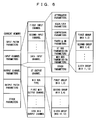
- FIG 8 a flowchart of processing executed by the CPU 11 when an instruction to store a preset is detected is shown in FIG 8 .
- the CPU 11 of the digital mixer 10 Upon detection of the instruction to store parameters for the i-th input channel as the p-th preset by the user via a not-shown user interface, the CPU 11 of the digital mixer 10 starts the processing shown in the flowchart in FIG 8 .
- the CPU 11 first stores the preset name that has been inputted by the user or automatically set, into the storage area for the p-th preset in the preset library (S11). The CPU 11 then stores the information of the type of MIX buses in each group among the output channel parameters stored in the current memory into the storage area for the p-th preset (S12).
- the CPU 11 stores the values of the parameters for the i-th input channel stored in the current memory into the storage area corresponding to the p-th preset (S 13 to S16), and ends the processing.
- the CPU 11 functions as a storing device and stores the parameters of one input channel and the type of each MIX bus into the preset library as a preset shown in FIG 7 .
- FIG 9 a flowchart of processing executed by the CPU 11 when an instruction to recall the preset is detected is shown in FIG 9 .
- the CPU 11 of the digital mixer 10 Upon detection of the instruction to recall the p-th preset into the i-th input channel by the user via the not-shown user interface, the CPU 11 of the digital mixer 10 starts the processing shown in the flowchart in FIG 9 .
- the CPU 11 first writes the values of the parameters of the portion having a common configuration irrespective of the type of the MIX buses, from the attenuator parameters to the ST bus transmission parameters among the p-th preset, into the storage area for corresponding parameters for the i-th input channel in the current memory (S21, S22).
- the CPU 11 writes the values of the MIX bus transmission parameters by executing the processing from Step S24 to Step S27 while sequentially incrementing the variable n from 1 to 6 (S23, S28, and S29).
- the CPU 11 first compares the type of the MIX buses of the n-th group in the p-th preset concerning to the recall with the type of those buses set in the current memory (S24). When the types coincide with each other (S25), it is recognized that the format of the transmission parameters for the MIX buses in the n-th group in the p-th preset coincides with the format of those parameters in the current memory. The CPU 11 therefore just writes the values of the transmission parameters for the MIX buses in the n-th group in the p-th preset into the storage area for the corresponding parameters for the i-th input channel in the current memory (S26).
- the format of the transmission parameters for the MIX buses in the n-th group in the p-th preset is different from the format of those parameters in the current memory, so that the CPU 11 cannot write the values of the parameters appropriately as they are.
- the CPU 11 performs a later-described predetermined conversion on the values of the transmission parameters for the MIX buses in the n-th group in the p-th preset to thereby convert the values in the preset into values of the parameters in the format corresponding to the bus type in the current memory, and then writes the values after the conversion into the storage area of the corresponding parameters for the i-th input channel in the current memory (S27).
- the CPU 11 functions as a recalling device and recalls the data of the preset stored in the preset library as the values of the parameters for one arbitrary input channel.
- the CPU 11 since the type of MIX buses at the time of the recall is different from the type at the time of the store of the preset, the user does not have to pay attention at all to the difference in the type because the format of the parameters are automatically converted.
- values of the parameters corresponding to the type of the buses selected at the time of the recall can be obtained based on the values of the parameters in a preset so that signals as close as possible to the signals which have been supplied to the MIX buses under the conditions at the time of the store including the type can be supplied to the MIX buses even when the signal transmission paths according to the type set at the time of the recall is used.
- the gains of the send level faders 52a and 52b are adjusted so that the signal which has been adjusted in level by the send level fader 55 and distributed by the pan 57 is supplied to each bus.
- the gain of the send level fader 55 for the stereo type is adjusted by the adjustment values indicating the distribution ratio between the right and left buses by the pan 57 to obtain the send level parameters of the send level faders corresponding to the bus on the L side and the bus on the R side.
- adjustment values obtained by the above expressions are the adjustment values in linear representation which indicate the ratio between the level of the signal after gain adjustment by the send level fader 55 and the level of the signals after gain adjustment by the send level faders 52a and 52b.
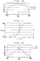
- FIG 10 a graph depicting the relations between the decibel-converted adjustment values ⁇ L1 and ⁇ L2 and the values of the pan parameter is shown in FIG 10 .
- the minimum value of the adjustment value is set at -50 decibels.
- the values of the send level parameters which should be set for the send level faders 52a and 52b respectively can be obtained by adding (corresponding to multiplication in the linear representation) the adjustment values to the send level parameter SLS of the fader 55 as shown in Table 1.
- the states of the PRE/POST switch 54 and the ON switch 56 for the stereo type may be just adopted as the states of the PRE/POST switches 51a and 51b and the states of the ON switches 52a and 52b.
- ⁇ L2/ ⁇ L1 represents the volume ratio between L and R when the signal in one system is distributed to the bus for L and the bus for R, and therefore it is found that the sound image localization position can be obtained based on the volume ratio between L and R from the Expression 3.
- FIG 11 A graph of the relation between the ratio between send levels corresponding to the two respective buses and the value of the pan parameter (PAN) calculated based on the Expression 3 is shown in FIG 11 .
- the actual values of the send level parameters (SL1, SL2) are represented in decibel, and therefore the horizontal axis is not in linear scale but in decibel scale.
- the ratio between the send levels in this case is the difference between SL2 and SL1.
- the state of the PRE/POST switches 51a and 51b corresponding to the two buses in the monaural type coincide with each other, the state may be just adopted as the state of the PRE/POST switch 54.
- the states of the ON switches 52a and 52b corresponding to the two buses for the monaural type coincide with each other, the states may be just adopted as the state of the ON switch 56.
- the PRE/POST switch 54 is set to PRE when the PRE/POST switches on both of two transmission paths in the monaural type are PRE and otherwise set to POST, and the ON switch 56 is set to ON when the ON switches on both of two transmission paths in the monaural type are ON and otherwise set to OFF here so that unintended high level signals are not outputted in the conditions set according to the preset.
- the preset can be recalled in the form available under the conditions at the time of the recall while maximally making use of the preset even when the type of the buses at the time of the recall is different from the type at the time of the store.
- the invention is applicable to the digital mixer 10 including minimally MIX buses for one group composed of two systems. Further, it is also conceivable that the processing of parameter conversion as in FIG 9 is applied only to a part of buses, and the following handling is performed for the other buses: in the case where the type of the buses at the time of the recall of the preset is different from the type at the time of the store, such a recall is regarded as an error and the recall is stopped, or the parameters regarding a part of the buses whose type at the time of the recall is different from the type at the time of the store is not recalled among the recalled preset.
- the digital mixer 10 can also be realized not only by the dedicated hardware but also as the function of a DAW (Digital Audio Workstation) application running on a PC.
- DAW Digital Audio Workstation
- the digital mixer of the invention it is possible, in the case where a monaural or stereo type can be selected for a pair of mixing buses and in the case where parameters for one input channel can be stored and recalled, the values of parameters relating to signal transmission from the input channel to the mixing buses can be appropriately recalled even when the type of the buses at the time of recalling the parameters is different from the type of the buses at the time of storing the parameters.
- application of the invention can improve the operability of the digital mixer.
Landscapes
- Engineering & Computer Science (AREA)
- Signal Processing (AREA)
- Circuit For Audible Band Transducer (AREA)
- Amplifiers (AREA)
- Circuits Of Receivers In General (AREA)
Applications Claiming Priority (1)
| Application Number | Priority Date | Filing Date | Title |
|---|---|---|---|
| JP2009169204A JP5233886B2 (ja) | 2009-07-17 | 2009-07-17 | デジタルミキサ |
Publications (2)
| Publication Number | Publication Date |
|---|---|
| EP2278737A2 true EP2278737A2 (de) | 2011-01-26 |
| EP2278737A3 EP2278737A3 (de) | 2012-09-26 |
Family
ID=43033263
Family Applications (1)
| Application Number | Title | Priority Date | Filing Date |
|---|---|---|---|
| EP10169613A Withdrawn EP2278737A3 (de) | 2009-07-17 | 2010-07-15 | Digitalmischer |
Country Status (3)
| Country | Link |
|---|---|
| US (1) | US8498432B2 (de) |
| EP (1) | EP2278737A3 (de) |
| JP (1) | JP5233886B2 (de) |
Families Citing this family (2)
| Publication number | Priority date | Publication date | Assignee | Title |
|---|---|---|---|---|
| JP6236748B2 (ja) * | 2015-03-25 | 2017-11-29 | ヤマハ株式会社 | 音処理装置 |
| EP3501170A4 (de) * | 2016-08-19 | 2020-01-01 | Oiid, LLC | Interaktive erzeugung von musik sowie wiedergabeverfahren und -system |
Citations (2)
| Publication number | Priority date | Publication date | Assignee | Title |
|---|---|---|---|---|
| JP3266045B2 (ja) | 1997-04-11 | 2002-03-18 | ヤマハ株式会社 | ステレオシステム |
| JP2007053631A (ja) | 2005-08-18 | 2007-03-01 | Yamaha Corp | デジタルミキサ |
Family Cites Families (7)
| Publication number | Priority date | Publication date | Assignee | Title |
|---|---|---|---|---|
| JP4062905B2 (ja) * | 2001-10-24 | 2008-03-19 | ヤマハ株式会社 | ディジタル・ミキサ |
| JP4448647B2 (ja) * | 2002-07-18 | 2010-04-14 | ヤマハ株式会社 | 音響信号処理装置 |
| JP3988692B2 (ja) * | 2003-07-25 | 2007-10-10 | ヤマハ株式会社 | 音響信号処理装置 |
| JP4321259B2 (ja) * | 2003-12-25 | 2009-08-26 | ヤマハ株式会社 | ミキサ装置およびミキサ装置の制御方法 |
| JP4645347B2 (ja) * | 2005-07-29 | 2011-03-09 | ヤマハ株式会社 | ミキシング装置及びプログラム |
| US7698009B2 (en) * | 2005-10-27 | 2010-04-13 | Avid Technology, Inc. | Control surface with a touchscreen for editing surround sound |
| JP5358889B2 (ja) * | 2007-02-28 | 2013-12-04 | ヤマハ株式会社 | ミキシング装置 |
-
2009
- 2009-07-17 JP JP2009169204A patent/JP5233886B2/ja not_active Expired - Fee Related
-
2010
- 2010-07-15 EP EP10169613A patent/EP2278737A3/de not_active Withdrawn
- 2010-07-16 US US12/837,760 patent/US8498432B2/en not_active Expired - Fee Related
Patent Citations (2)
| Publication number | Priority date | Publication date | Assignee | Title |
|---|---|---|---|---|
| JP3266045B2 (ja) | 1997-04-11 | 2002-03-18 | ヤマハ株式会社 | ステレオシステム |
| JP2007053631A (ja) | 2005-08-18 | 2007-03-01 | Yamaha Corp | デジタルミキサ |
Also Published As
| Publication number | Publication date |
|---|---|
| US8498432B2 (en) | 2013-07-30 |
| EP2278737A3 (de) | 2012-09-26 |
| JP2011024114A (ja) | 2011-02-03 |
| US20110064248A1 (en) | 2011-03-17 |
| JP5233886B2 (ja) | 2013-07-10 |
Similar Documents
| Publication | Publication Date | Title |
|---|---|---|
| US8050426B2 (en) | Digital mixer apparatus and editing method therefor | |
| US9385824B2 (en) | Digital mixer | |
| US8335325B2 (en) | Audio signal processing apparatus mixing plurality of input audio signals | |
| US20020193894A1 (en) | Configuration method of digital audio mixer | |
| US7689307B2 (en) | Digital audio mixer | |
| US20110228956A1 (en) | Digital audio mixer | |
| US7499558B2 (en) | Digital mixer | |
| US7483541B2 (en) | Digital mixer | |
| US7139624B2 (en) | Audio signal processing device | |
| US8498432B2 (en) | Digital mixer and method of controlling the same | |
| US9860002B2 (en) | Audio signal processing apparatus and storage medium | |
| US9325439B2 (en) | Audio signal processing device | |
| US7392103B2 (en) | Audio signal processing device | |
| US8743120B2 (en) | Controller | |
| US20190356291A1 (en) | Parameter setting device and parameter setting method | |
| JP3772803B2 (ja) | 信号処理装置及び該装置の制御プログラム | |
| JP4210952B2 (ja) | ディジタルミキサ | |
| JP4609234B2 (ja) | デジタルミキサ | |
| US10534572B2 (en) | Control device, control method, and storage medium storing a program | |
| JP4596262B2 (ja) | デジタルミキサおよびプログラム | |
| JP2007074623A (ja) | デジタルミキサおよびプログラム | |
| JP2005223603A (ja) | パラメータ表示装置及びそのプログラム | |
| JP4063227B2 (ja) | 音響機器の制御装置 | |
| US20190179599A1 (en) | Information processing method, information processor, and audio device | |
| JP2009239805A (ja) | ミキサ装置 |
Legal Events
| Date | Code | Title | Description |
|---|---|---|---|
| PUAI | Public reference made under article 153(3) epc to a published international application that has entered the european phase |
Free format text: ORIGINAL CODE: 0009012 |
|
| AK | Designated contracting states |
Kind code of ref document: A2 Designated state(s): AL AT BE BG CH CY CZ DE DK EE ES FI FR GB GR HR HU IE IS IT LI LT LU LV MC MK MT NL NO PL PT RO SE SI SK SM TR |
|
| AX | Request for extension of the european patent |
Extension state: BA ME RS |
|
| PUAL | Search report despatched |
Free format text: ORIGINAL CODE: 0009013 |
|
| AK | Designated contracting states |
Kind code of ref document: A3 Designated state(s): AL AT BE BG CH CY CZ DE DK EE ES FI FR GB GR HR HU IE IS IT LI LT LU LV MC MK MT NL NO PL PT RO SE SI SK SM TR |
|
| AX | Request for extension of the european patent |
Extension state: BA ME RS |
|
| RIC1 | Information provided on ipc code assigned before grant |
Ipc: H04H 60/04 20080101AFI20120823BHEP |
|
| 17P | Request for examination filed |
Effective date: 20130325 |
|
| STAA | Information on the status of an ep patent application or granted ep patent |
Free format text: STATUS: THE APPLICATION HAS BEEN WITHDRAWN |
|
| 18W | Application withdrawn |
Effective date: 20161115 |