EP2276386B1 - Wasserführendes haushaltsgerät - Google Patents
Wasserführendes haushaltsgerät Download PDFInfo
- Publication number
- EP2276386B1 EP2276386B1 EP09727577.0A EP09727577A EP2276386B1 EP 2276386 B1 EP2276386 B1 EP 2276386B1 EP 09727577 A EP09727577 A EP 09727577A EP 2276386 B1 EP2276386 B1 EP 2276386B1
- Authority
- EP
- European Patent Office
- Prior art keywords
- cable holder
- dishwasher
- door
- cable
- appliance
- Prior art date
- Legal status (The legal status is an assumption and is not a legal conclusion. Google has not performed a legal analysis and makes no representation as to the accuracy of the status listed.)
- Active
Links
Images
Classifications
-
- A—HUMAN NECESSITIES
- A47—FURNITURE; DOMESTIC ARTICLES OR APPLIANCES; COFFEE MILLS; SPICE MILLS; SUCTION CLEANERS IN GENERAL
- A47L—DOMESTIC WASHING OR CLEANING; SUCTION CLEANERS IN GENERAL
- A47L15/00—Washing or rinsing machines for crockery or tableware
- A47L15/42—Details
- A47L15/4251—Details of the casing
- A47L15/4274—Arrangement of electrical components, e.g. control units or cables
-
- A—HUMAN NECESSITIES
- A47—FURNITURE; DOMESTIC ARTICLES OR APPLIANCES; COFFEE MILLS; SPICE MILLS; SUCTION CLEANERS IN GENERAL
- A47L—DOMESTIC WASHING OR CLEANING; SUCTION CLEANERS IN GENERAL
- A47L15/00—Washing or rinsing machines for crockery or tableware
- A47L15/42—Details
- A47L15/4251—Details of the casing
- A47L15/4257—Details of the loading door
-
- A—HUMAN NECESSITIES
- A47—FURNITURE; DOMESTIC ARTICLES OR APPLIANCES; COFFEE MILLS; SPICE MILLS; SUCTION CLEANERS IN GENERAL
- A47L—DOMESTIC WASHING OR CLEANING; SUCTION CLEANERS IN GENERAL
- A47L15/00—Washing or rinsing machines for crockery or tableware
- A47L15/42—Details
- A47L15/44—Devices for adding cleaning agents; Devices for dispensing cleaning agents, rinsing aids or deodorants
- A47L15/4409—Devices for adding cleaning agents; Devices for dispensing cleaning agents, rinsing aids or deodorants by tipping containers or opening their lids, e.g. with the help of a programmer
Definitions
- the invention relates to a dishwasher as a water-carrying household appliance.
- Water-bearing household appliances such as Dishwashers have an appliance door with which the treatment container, in the case of a dishwasher the interior of the dishwasher can be opened and closed.
- An electrical component in the form of an addition device is arranged on the inside of the appliance door and is used to dispense dishwasher detergent and / or rinse aid into the interior of the dishwasher.
- the fully assembled door of a dishwasher has a button assembly or control panel in its upper area.
- the front panel 100 of the button assembly has an externally accessible handle 110 for opening and closing the door.
- the fully assembled front door of the dishwasher of the Figure 1 the older, republished EP 2 016 883 A1 provides in its upper area a control panel with a handle opening or recess 16 accessible from the front.
- the object of the invention is to develop a dishwasher in such a way that opening and / or closing the appliance door is easier.
- the invention is based on a dishwasher as a water-carrying household appliance, having at least one appliance door on which a cable holder is arranged.
- the cable holder has a handle for pivoting the appliance door of the household appliance. In this way, the usability is increased in a simple manner without the installation of an additional component being necessary for this.
- an electrical component is arranged on the inside of the appliance door.
- the electrical component is an addition device.
- the addition device serves to add detergents and rinse aid to the interior of a dishwasher and is connected to a control unit of the dishwasher via electrical lines.
- a cable holder for at least one cable in particular for electrical lines or glass fiber cables, is provided for cable routing, said cable holder having at least one guide section for guiding the at least one cable.
- the at least one guide section is fastened to an inner door part of the appliance door.
- the at least one guide section is detachably connected to the electrical component.
- the at least one guide section of the cable holder is preferably not arranged rigidly, but pivotably on the cable holder.
- the one or preferably two guide sections of the cable holder can therefore be arranged in a common mounting plane in which the two guide sections enclose an angle of 180 ° for easy assembly in terms of assembly of the power supply cables. When assembling, the cables are therefore not complex to run around edges.
- the cable holder can be moved into a compact packaging position for storage with reduced installation space. In the packaging position, for example, both guide sections can lie side by side, which means that an angle between the two guide sections is zero. Only during final assembly can the two guide sections of the cable holder be brought into their angled installation position.
- the cable holder For easy handling of the cable holder, its two guide sections can be connected to one another via a joint, for example a hinge area, in particular a film hinge.
- a joint for example a hinge area, in particular a film hinge.
- the guide sections can be opened up into an installation position or an assembly position or, alternatively, folded up into a packaging position.
- the two guide sections of the cable holder can preferably be positioned directly on the electrical component of the household appliance in a shape-matched manner.
- a snap-in connection between the guide sections and the electrical component is tool-free.
- the two mutually adjustable guide sections of the cable holder can be completely folded together in their packaging position, so that both guide sections are in contact with one another with their long sides.
- at least one of the above-mentioned latching elements in a double function can serve not only for the latching connection with the electrical component, but at the same time also for securing on the adjacent guide section and correspondingly be in latching engagement with the latter.
- the cable holder can be used in a domestic appliance, in particular a water-bearing domestic appliance such as. B. a dishwasher or washing machine.
- a dishwasher usually has in its appliance door on the inner door panel part a housing of an addition device, which is an electrical component in the sense of the invention.
- the feed device is provided with electrical actuating elements, for example a magnetic coil and an electrical rinse aid indicator.
- the cable holder can be held in the installed position on the housing of the feed device via the locking elements mentioned.
- the appliance door of the dishwasher can be designed with a door inner panel part facing the washing container, on the outside of which a door outer part, for example a closed front panel or a furniture panel, is provided.
- a door outer part for example a closed front panel or a furniture panel.
- the trough-shaped part that is still open on the front is first made Inner door panel part hinged to the dishwasher via side hinge levers.
- one of the guide sections of the cable holder can be designed with a handle.
- the handle can be a handle bar pulled up by the guide section.
- the catches of the cable holder on the housing of the feed device must be stable enough. It is therefore preferred if, in addition to the catches on the housing of the feed device, at least one guide section of the calf holder is also coupled directly to the inner door panel of the appliance door. Tractive forces that are exerted on the cable holder when the handle is actuated can therefore be reliably absorbed by the inner door panel.
- the guide sections, together with the hinge area and the latching elements are made of the same material and / or in one piece.
- the cable holder can be easily manufactured as an injection molded part.
- the cable holder can in particular be produced advantageously with simple shaping tools without additional sliding components at an angle of 180 ° between the two guide sections.
- the invention also includes a cable holder for a water-carrying household appliance according to the invention.
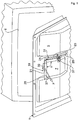
- Fig. 1 shows a dishwasher which has not yet been fully assembled and has an appliance door 1 which opens or closes a front loading opening of a washing compartment 2 of the dishwasher. This is pivoted in a known manner on the bottom of the dishwasher about a horizontal axis of rotation.
- the appliance door 1 has, in the customary manner, a door inner panel part 5 and an outer door element mounted thereon, for example a front panel or a furniture panel, in the fully assembled state. In the Fig. 1 this outer door element is omitted for reasons of clarity, so that the inner door panel part 5 is exposed.
- an appliance 7 for dosing a cleaning agent is integrated in the appliance door 1.
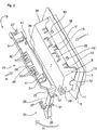
- the inner door panel part 5 according to the Fig. 2 an approximately central mounting opening 9, from the edges of which protrude mounting flanges 11 on the side facing away from the washing compartment 2.
- the feed device 7 is according to the Fig. 1 inserted in a mounting direction I into the mounting opening 9 until the locking projections 15 provided on the edge sides 12, 13 of the feed device 7 engage behind the mounting flanges 11, as shown in FIG Fig. 2 is shown.
- the addition device 7 is controlled by an electronic control device, which is also integrated in the appliance door 1.
- the control device is also in signal connection with an electronic rinse aid display integrated in the addition device 7.
- the power supply cables 17 are held in a cable routing element 19, which in the Fig. 1 is shown in its installation position.
- the cable routing element 19 has according to the Fig. 1 two guide sections 21, 23 angled to one another by an angle ⁇ 1 of 90 °. These also encompass each other at right angles vertical and horizontal edge sides 12, 13 of the feed device 7.
- the cable holder 19 guides the cable along the two edge sides 12, 13 up to the level of the respective connection sockets (not shown) of the feed device 7.
- the cable holder 19 is a one-piece plastic injection molded part that is made of the same material.
- the two strip-shaped guide sections 21, 23 are pivotally connected to one another via a film hinge 25 and frame the feed device 7 approximately in half.
- the cables 17 are therefore looped around the lower end 26 of the guide section 23 and in opposite directions back to the corresponding connection socket of the feed device 7.
- the cable loops formed in this way allow liquid drops to drip off, possibly running along the cables 17.
- the guide section 21 of the cable holder 19 lying horizontally in the installed position surrounds the housing edge 28 with its angled free end 27.
- the free end 27 of the horizontal guide section 21 is according to FIG Fig. 2 an elastically resilient tab is provided which, in the installed position, presses against a vertical edge of the feed device.
- the two guide sections 21, 23 of the cable holder 19 have boundary walls 29 on the front.
- fastening clips 31 are provided on each of the guide sections 21, 23 and fix the cables 17 to the bottom 32 of the guide sections 21, 23 of the cable holder 19.
- the horizontal guide section 21 of the cable holder 19 has according to the Fig. 2 still resilient snap hook 33. These are aligned horizontally against the mounting direction I and are formed below the bottom 32 of the guide section 21 on the front boundary wall 29.
- a handle bar 39 is formed on the bottom 32 of the guide section 21.
- the handle bar 39 extends approximately centrally along the guide section 21 on the side opposite the front wall 29.
- the handle bar 39 is gripped by the fitter and with the in Fig. 1 indicated operating force F is applied.
- the upper latching connection provided between the latching hooks 33 and the latching openings 35 of the feed device 7 is to be dimensioned accordingly in order to hold the cable holder 19 stably on the feed device 7 when the actuating force F is applied.
- additional locking projections 41 can be provided on the bottom 32 of the guide portion, as in the Fig. 2 are indicated.
- the latching projections 41 together with corresponding latching openings 43 in the fastening flange 11 of the inner door panel part 5 can provide additional latching.
- the cable holder 19 is not only positively connected to the feed device 7, but also to the inner door panel part 5.
- the cable holder 19 is manufactured using the plastic injection molding process.
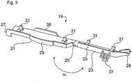
- the cable holder 19 is manufactured in an injection molding chamber with guide sections 21, 23 which are folded apart and aligned in the longitudinal direction, as shown in FIG Fig. 3 are shown.
- the angle ⁇ 2 between the two guide sections 21, 23 is 180 ° in the production position shown. Due to the unfolded position of the two guide sections 21, 23, simple injection molds can be used without the need for additional sliding components.
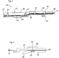
- the cable holder 19 equipped with the cables 17 can be adjusted around the film hinge 25 into a packaging position, as shown in FIG Fig. 5 is shown.
- the two guide sections 21, 23 are completely folded together.
- the cable holder 19 thus assumes an extremely compact, closed geometry in which the angle ⁇ 3 between the two guide sections 21, 23 is reduced to zero.
- Such folded cable holders 19 can be packed or stored in large numbers in a space-saving manner.
- the locking pin 37 of the vertical guide section 23 in the installed position engages in a corresponding locking receptacle 45 which is provided in the bottom 32 of the horizontal guide section 21 in the installed position.
- the latching pin 37 thus serves a dual function in the installed position for lateral latching with the feed device 7 and in the packaging position for latching with the guide section 21.
Landscapes
- Washing And Drying Of Tableware (AREA)
- Electric Cable Arrangement Between Relatively Moving Parts (AREA)
Description
- Die Erfindung betrifft eine Geschirrspülmaschine als wasserführendes Haushaltsgerät.
- Wasserführende Haushaltsgeräte wie z.B. Geschirrspülmaschinen weisen eine Gerätetür auf, mit der der Behandlungsbehälter, im Fall einer Geschirrspülmaschine der Innenraum der Geschirrspülmaschine geöffnet und geschlossen werden kann. Innenseitig ist an der Gerätetür ein elektrisches Bauteil in Form eine Zugabeeinrichtung angeordnet, die dazu dient Geschirrspülreiniger und/oder Klarspüler in den Innenraum der Geschirrspülmaschine abzugeben.
- Während der Montage der Geschirrspülmaschine kann es erforderlich sein, eine keinen Griff aufweisende Gerätetür zu öffnen oder zu schließen.
- Gemäß den
Figuren 2 und3 der vorveröffentlichtenDE 10 2005 050 592 A1 verfügt die fertig zusammengebaute Tür einer Geschirrspülmaschine über eine Tastenbaugruppe bzw. Bedienblende in ihrem oberen Bereich. Die Frontplatte 100 der Tastenbaugruppe weist einen von außen zugänglichen Griff 110 zum Öffnen und Schließen der Tür auf. - Die fertig montierte Fronttür der Geschirrspülmaschine der
Figur 1 der älteren, nachveröffentlichtenEP 2 016 883 A1 sieht in ihrem oberen Bereich eine Bedienblende mit einer von vorne zugänglichen Grifföffnung bzw. Griffmulde 16 vor.
Die Aufgabe der Erfindung besteht darin, eine Geschirrspülmaschine derart weiterzubilden, dass Öffnen und/oder Schließen der Gerätetür zu erleichtern. - Die Aufgabe der Erfindung ist durch die Merkmale des Patentanspruches 1 gelöst. Vorteilhafte Weiterbildungen der Erfindung sind in den jeweiligen Unteransprüchen offenbart.
- Die Erfindung geht aus von einer Geschirrspülmaschine als wasserführendes Haushaltsgerät, wenigstens eine Gerätetür aufweisend, an der ein Kabelhalter angeordnet ist.
- Erfindungsgemäß ist vorgesehen, dass der Kabelhalter einen Handgriff zur Schwenkbetätigung der Gerätetür des Haushaltsgeräts aufweist. So wird auf einfache Weise die Bedienbarkeit erhöht, ohne das hierfür die Montage eines zusätzlichen Bauteils erforderlich ist.
- Erfindungsgemäß ist dabei an der Gerätetür innenseitig ein elektrisches Bauteil angeordnet ist. Erfindungsgemäß ist vorgesehen, dass das elektrische Bauteil eine Zugabeeinrichtung ist. Die Zugabeeinrichtung dient der Zugabe von Reinigungsmitteln und Klarspüler in den Innenraum einer Geschirrspülmaschine und ist hierzu über elektrische Leitungen mit einer Steuerung der Geschirrspülmaschine verbunden.
- Zur Kabelführung ist erfindungsgemäß ein Kabelhalter für wenigstens ein Kabel, insbesondere für elektrische Leitungen oder Glasfaserkabel, vorgesehen, der wenigstens einen Führungsabschnitt zum Führen des wenigstens einen Kabels aufweist.
- Schließlich ist erfindungsgemäß vorgesehen dass der wenigstens eine Führungsabschnitt an einem Türinnenteil der Gerätetür befestigt ist. In einer alternativen Ausführungsform ist erfindungsgemäß vorgesehen, dass der wenigstens eine Führungsabschnitt lösbar mit dem elektrischen Bauteil verbunden ist.
- Vorzugsweise ist der wenigstens eine Führungsabschnitte des Kabelhalters nicht starr, sondern verschwenkbar am Kabelhalter angeordnet. Der eine oder vorzugsweise zwei Führungsabschnitte des Kabelhalters können daher für ein montagetechnisch einfaches Bestücken der Stromversorgungskabel zueinander ausgerichtet in einer gemeinsamen Montageebene angeordnet werden, bei der die beiden Führungsabschnitte einen Winkel von 180° einschließen. Beim Bestücken sind daher die Kabel nicht montagetechnisch aufwendig um Kanten herum zu führen. Außerdem kann der Kabelhalter für eine bauraumreduzierte Lagerung in eine kompakte Verpackungslage verstellt werden. In der Verpackungslage können beispielhaft beide Führungsabschnitte seitlich aneinander liegen, das heißt, dass ein Winkel zwischen beiden Führungsabschnitten bei Null liegt. Erst bei der Endmontage können die beiden Führungsabschnitte des Kabelhalters in ihre zueinander abgewinkelte Einbaulage verbracht werden.
- Für eine einfache Handhabung des Kabelhalters können seine beiden Führungsabschnitte über ein Gelenk, bspw. einen Scharnierbereich, insbesondere ein Filmscharnier, miteinander in Verbindung sein. In diesem Fall können die Führungsabschnitte in Abhängigkeit vom jeweiligen Montageschritt in eine Einbaulage oder eine Bestückungslage aufgeklappt werden oder alternativ in eine Verpackungslage zusammengeklappt werden.
- Bevorzugt können die beiden Führungsabschnitte des Kabelhalters in ihrer Einbaulage unmittelbar konturangepasst am elektrischen Bauteil des Haushaltsgerätes positioniert werden. Montagetechnisch günstig ist hierbei eine werkzeugfrei erfolgende Rastverbindung zwischen den Führungsabschnitten und dem elektrischen Bauteil.
- Bevorzugt können die beiden, gegeneinander verstellbaren Führungsabschnitte des Kabelhalters in ihrer Verpackungslage vollständig zusammengeklappt sein, so dass beide Führungsabschnitte mit ihren Längsseiten in Anlage zueinander sind. In diesem Fall kann zumindest eines der oben erwähnten Rastelemente in Doppelfunktion nicht nur zur Rastverbindung mit dem elektrischen Bauteil, sondern zugleich auch zur Sicherung am benachbarten Führungsabschnitt dienen und entsprechend mit diesem in Rasteingriff sein.
- In einer besonderen Ausführungsform kann der Kabelhalter zur Anwendung in einem Hausgerät, insbesondere einem wasserführenden Haushaltsgerät wie z. B. einer Geschirrspül- oder Waschmaschine angepasst sein. Eine Geschirrspülmaschine weist üblicherweise in ihrer Gerätetür am Türinnenblechteil ein Gehäuse einer Zugabeeinrichtung auf, die ein elektrisches Bauteil im Sinne der Erfindung darstellt. Die Zugabeeinrichtung ist bekanntermaßen mit elektrischen Betätigungselementen, etwa einer Magnetspule sowie einer elektrischen Klarspülanzeige, versehen. Der Kabelhalter kann über die erwähnten Rastelemente in Einbaulage am Gehäuse der Zugabeeinrichtung gehaltert sein.
- Die Gerätetür der Geschirrspülmaschine kann mit einem, dem Spülbehälter zugewandten Türinnenblechteil ausgeführt sein, an dessen Außenseite ein Türaußenteil, etwa eine geschlossene Frontblende oder eine Möbelplatte, vorgesehen ist. Bei der werksseitigen Montage der Gerätetür wird zunächst das frontseitig noch offene, wannenförmige Türinnenblechteil über seitliche Scharnierhebel an der Geschirrspülmaschine angelenkt. Um in diesem Montagezustand eine Schwenkbetätigung des an der Geschirrspülmaschine angelenkten Türinnenblechteils zu vereinfachen, kann einer der Führungsabschnitte des Kabelhalters mit einem Handgriff ausgeführt sein. Der Handgriff kann eine vom Führungsabschnitt hochgezogene Griffleiste sein.
- Für eine sichere Betätigung des am Führungsabschnitt gebildeten Handgriffes müssen die Verrastungen des Kabelfhalters am Gehäuse der Zugabeeinrichtung stabil genug ausgeführt sein. Bevorzugt ist es deshalb, wenn zusätzlich zu den Verrastungen am Gehäuse der Zugabeeinrichtung zumindest ein Führungsabschnitt des Kalbelhalters zusätzlich auch unmittelbar am Türinnenblech der Gerätetür gekoppelt ist. Zugkräfte, die beim Betätigen des Handgriffes auf den Kabelhalter ausgeübt werden, können daher zuverlässig vom Türinnenblech aufgenommen werden.
- Fertigungstechnisch bevorzugt ist es, wenn die Führungsabschnitte zusammen mit dem Scharnierbereich und dem Rastelementen materialeinheitlich und/oder einstückig ausgebildet sind. In diesem Fall kann der Kabelhalter fertigungstechnisch einfach als Spritzgussteil hergestellt werden. Der Kabelhalter kann insbesondere bei einem Winkel von 180° zwischen den beiden Führungsabschnitten vorteilhaft mit einfachen Formwerkzeugen ohne zusätzliche Schiebekomponenten hergestellt werden.
- Ferner gehört zur Erfindung ein Kabelhalter für ein erfindungsgemäßes wasserführendes Haushaltsgerät.
- Nachfolgend ist ein Ausführungsbeispiel der Erfindung anhand der beigefügten Figuren gezeigt.
- Es zeigen:
- Fig. 1
- in einer schematischen Perspektivdarstellung eine Geschirrspülmaschine, bei deren Gerätetür ein außenseitiges Frontelement entfernt ist;
- Fig. 2
- in einer perspektivischen Detailansicht einen Montageschritt zur Halterung des Kabelhalters am Gehäuse der Zugabeeinrichtung der Geschirrspülmaschine;
- Fig. 3
- der Kabelhalter in Alleinstellung;
- Fig. 4
- der Kabelhalter nach erfolgter Bestückung mit Stromversorgungskabeln; und
- Fig. 5
- der Kabelhalter in einer Verpackungslage.
- In der
Fig. 1 ist eine noch nicht fertig montierte Geschirrspülmaschine mit einer Gerätetür 1 gezeigt, die eine frontseitige Beschickungsöffnung eines Spülbehälters 2 der Geschirrspülmaschine öffnet oder schließt. Diese ist in bekannter Weise bodenseitig um eine horizontale Drehachse schwenkbar an der Geschirrspülmaschine angelenkt. Die Gerätetür 1 weist in üblicher Weise im fertig montierten Zustand ein Türinnenblechteil 5 sowie ein daran montiertes äußeres Türelement, etwa eine Frontblende oder eine Möbelplatte, auf. In derFig. 1 ist dieses Türaußenelement aus Gründen der Übersichtlichkeit weggelassen, so dass das Türinnenblechteil 5 freigelegt ist. - Wie aus der
Fig. 1 hervorgeht, ist in der Gerätetür 1 eine Zugabeeinrichtung 7 zum Dosieren eines Reinigungsmittels integriert. Zur Halterung der Zugabeeinrichtung 7 weist das Türinnenblechteil 5 gemäß derFig. 2 eine in etwa mittige Montageöffnung 9 auf, von deren Rändern auf der vom Spülbehälter 2 abgewandten Seite Befestigungsflansche 11 abragen. Die Zugabeeinrichtung 7 wird gemäß derFig. 1 in einer Montagerichtung I in die Montageöffnung 9 eingeschoben, bis die an den Randseiten 12, 13 der Zugabeeinrichtung 7 vorgesehenen Rastvorsprünge 15 die Befestigungsflansche 11 hintergreifen, wie es in derFig. 2 gezeigt ist. - Zur Dosierung des Reinigungsmittels während eines Spülvorganges wird die Zugabeeinrichtung 7 von einer, ebenfalls in der Gerätetür 1 integrierten elektronischen Steuereinrichtung angesteuert. Die Steuereinrichtung ist außerdem mit einer in der Zugabeeinrichtung 7 integrierten elektronischen Klarspülanzeige in Signalverbindung. Für eine einwandfreie, genau definierte Kabelführung zwischen der Steuereinrichtung und der Zugabeeinrichtung 7 sind die Stromversorgungskabel 17 in einem Kabelführungselement 19 gehalten, das in der
Fig. 1 in seiner Einbaulage gezeigt ist. Das Kabelführungselement 19 weist gemäß derFig. 1 zwei zueinander um einen Winkel α1 von 90° abgewinkelte Führungsabschnitte 21, 23 auf. Diese umgreifen ebenfalls zueinander rechtwinklige vertikale und horizontale Randseiten 12, 13 der Zugabeeinrichtung 7. Mittels des Kabelhalters 19 erfolgt eine Kabelführung entlang der beiden Randseiten 12, 13 bis auf Höhe der jeweiligen, nicht gezeigten Anschlussbuchsen der Zugabeeinrichtung 7. - Der Kabelhalter 19 ist hier ein einstückig sowie materialeinheitlich ausgebildetes Kunststoffspritzgussteil. Die beiden leistenförmigen Führungsabschnitte 21, 23 sind über ein Filmscharnier 25 schwenkbar miteinander in Verbindung und umrahmen die Zugabeeinrichtung 7 in etwa zur Hälfte. Dabei erstreckt sich der in der
Fig. 1 vertikal eingebaute Führungsabschnitt 23 über die untere Gehäusekante der Zugabeeinrichtung 7 hinaus nach unten. Die Kabel 17 werden daher schlaufenartig um das untere Ende 26 des Führungsabschnittes 23 und gegenläufig wieder zurück zur entsprechenden Anschlussbuchse der Zugabeeinrichtung 7 geführt. Die so gebildeten Kabel-Schlaufen ermöglichen ein Abtropfen von, gegebenenfalls an den Kabeln 17 entlang laufenden Flüssigkeitstropfen. - Der in Einbaulage horizontal liegende Führungsabschnitt 21 des Kabelhalters 19 umgreift demgegenüber mit seinem abgewinkelten freien Ende 27 die Gehäusekante 28. Am freien Ende 27 des horizontalen Führungsabschnittes 21 ist gemäß der
Fig. 2 eine elastisch federnde Lasche vorgesehen, die in Einbaulage gegen eine vertikale Randseite der Zugabeeinrichtung drückt. - Zur seitlichen Abschirmung der Kabel 17 weisen die beiden Führungsabschnitte 21, 23 des Kabelhalters 19 frontseitige Begrenzungswände 29 auf. Außerdem sind an jedem der Führungsabschnitte 21, 23 Befestigungsclips 31 vorgesehen, die die Kabel 17 am Boden 32 der Führungsabschnitte 21, 23 des Kabelhalters 19 fixieren.
- Der horizontale Führungsabschnitt 21 des Kabelhalters 19 weist gemäß der
Fig. 2 weiterhin elastisch federnde Rasthaken 33 auf. Diese sind entgegen der Montagerichtung I horizontal ausgerichtet und unterhalb des Bodens 32 des Führungsabschnittes 21 an der frontseitigen Begrenzungswand 29 angeformt. - Zur Montage des Kabelhalters 19 auf der Zugabeeinrichtung 7 wird gemäß der
Fig. 2 zunächst dessen horizontaler Führungsabschnitt 21 in der horizontalen Montagerichtung II auf die obere Randseite 13 der Zugabeeinrichtung 7 geschoben. Dabei werden die horizontal ausgerichteten Rasthaken 33 durch entsprechende Rastöffnungen 35 der Zugabeeinrichtung 7 geführt, bis die Rasthaken 33 die korrespondierenden Rastöffnungen 35 hintergreifen. Nach erfolgter Verrastung des horizontalen Führungsabschnittes 21 mit der Zugabeeinrichtung 7 wird der Führungsabschnitt 23 um das Filmscharnier 25 in der Montagerichtung III im Gegenuhrzeigersinn in seine vertikale Einbaulage geschwenkt. In der Einbaulage ist ein am vertikalen Führungsabschnitt 23 vorgesehener Rastzapfen 37 in Rastverbindung mit einer korrespondierenden, seitlich an der Zugabeeinrichtung 7 vorgesehenen Rastaufnahme 38. - Für eine einfache Handhabung der gemäß der
Fig. 1 an der Geschirrspülmaschine montierten Gerätetür 1 ist am Boden 32 des Führungsabschnittes 21 eine Griffleiste 39 angeformt. Die Griffleiste 39 erstreckt sich in etwa mittig entlang des Führungsabschnittes 21 auf der, der frontseitigen Begrenzungswand 29 gegenüberliegenden Seite. Zur Schwenkbetätigung des bereits am Gehäuse der Geschirrspülmaschine angelenkten Türinnenblechteils 5 wird die Griffleiste 39 vom Monteur hintergriffen und mit der in derFig. 1 angedeuteten Betätigungskraft F beaufschlagt. Die zwischen den Rasthaken 33 und den Rastöffnungen 35 der Zugabeeinrichtung 7 bereitgestellte obere Rastverbindung ist entsprechend zu dimensionieren, um den Kabelhalter 19 bei Beaufschlagung mit der Betätigungskraft F stabil an der Zugabeeinrichtung 7 zu halten. Zur Verstärkung dieser oberen Rastverbindung können am Boden 32 des Führungsabschnittes 21 zusätzliche Rastvorsprünge 41 vorgesehen werden, wie sie in derFig. 2 angedeutet sind. Beim Aufschieben des Kabelhalters 19 in der Montagerichtung II auf die Zugabeeinrichtung 7 können die Rastvorsprünge 41 zusammen mit korrespondierenden Rastöffnungen 43 im Befestigungsflansch 11 des Türinnenblechteils 5 eine zusätzliche Verrastung bereitstellen. In diesem Fall ist der Kabelhalter 19 nicht nur mit der Zugabeeinrichtung 7, sondern auch mit dem Türinnenblechteil 5 formschlüssig in Verbindung. - Wie bereits erwähnt, wird der Kabelhalter 19 im Kunststoffspritzgussverfahren hergestellt. Der Kabelhalter 19 wird in einer Spritzgusskammer mit auseinander geklappten, in Längsrichtung zueinander ausgerichteten Führungsabschnitten 21, 23 gefertigt, wie sie in der
Fig. 3 gezeigt sind. Der Winkel α2 zwischen beiden Führungsabschnitten 21, 23 liegt in der gezeigten Herstellungslage bei 180°. Aufgrund der aufgeklappten Lage der beiden Führungsabschnitte 21, 23 können einfache Spritzgussformwerkzeuge eingesetzt werden, ohne dass zusätzliche Schiebekomponenten erforderlich sind. - In der, in der
Fig. 3 gezeigten, in Längsrichtung ausgerichteten Herstellungslage der Führungsabschnitte 21, 23 erfolgt auch die Vormontage der Stromversorgungskabel 17 am Kabelführungselement 19, wie es in derFig. 4 gezeigt ist. Hierzu werden die Kabel 17 zwischen den Befestigungsclips 31 und dem Boden 32 der Führungsabschnitte 21, 23 geklemmt. Die Vormontage findet in einer gemeinsamen Montageebene statt, ohne dass die Kabel 17 montagetechnisch aufwendig um Kanten zwischen zueinander abgewinkelten Führungsabschnitten 21, 23 montiert werden müssten. Die in derFig. 4 gezeigte Vormontagelage des Kabelhalters 19 ist somit identisch mit seiner in derFig. 3 gezeigten Herstellungslage. - Nach erfolgter Vormontage kann der mit den Kabeln 17 bestückte Kabelhalter 19 um das Filmscharnier 25 in eine Verpackungsposition verstellt werden, wie sie in der
Fig. 5 gezeigt ist. In der gezeigten Verpackungsposition sind die beiden Führungsabschnitte 21, 23 vollständig zusammengeklappt. Der Kabelhalter 19 nimmt somit eine äußerst kompakte, geschlossene Geometrie ein, bei der der Winkel α3 zwischen den beiden Führungsabschnitten 21, 23 auf Null reduziert ist. Derart zusammengeklappte Kabelhalter 19 können in großer Anzahl raumgünstig verpackt bzw. gelagert werden. - Zur Sicherung der Verpackungsposition greift der Rastzapfen 37 des in Einbaulage vertikalen Führungsabschnittes 23 in eine entsprechende Rastaufnahme 45, die im Boden 32 des in Einbaulage horizontalen Führungsabschnittes 21 vorgesehen ist. Der Rastzapfen 37 dient somit in Doppelfunktion in der Einbaulage zur seitlichen Verrastung mit der Zugabeeinrichtung 7 sowie in Verpackungslage zur Verrastung mit dem Führungsabschnitt 21.
-
- 1
- Gerätetür
- 2
- Spülbehälter
- 3
- Drehachse
- 5
- Türinnenblechteil
- 7
- Zugabeeinrichtung
- 9
- Montageöffnung
- 11
- Befestigungsflansch
- 12
- Randseite der Zugabeeinrichtung 7
- 13
- Randseite der Zugabeeinrichtung 7
- 15
- Rastvorsprünge
- 17
- Stromversorgungskabel
- 19
- Kabelhalter
- 21, 23
- Führungsabschnitte
- 25
- Gelenk
- 26, 27
- freie Enden der Führungsabschnitte 21, 23
- 29
- Begrenzungswände
- 31
- Befestigungsclips
- 32
- Boden
- 33
- Rasthaken
- 35
- Rastöffnungen
- 37
- Rastzapfen
- 38
- Rastaufnahme
- 39
- Handgriff, Griffleiste
- 41
- zusätzliche Rastvorsprünge
- 43
- Rastöffnungen
- 45
- Rastaufnahme
- I, II, III
- Montagerichtungen
- F
- Betätigungskraft
- α
- Winkel, der zwischen den beiden Führungsabschnitten 21, 23 des Kabelführungselements 19 eingeschlossen ist
Claims (9)
- Haushalts- Geschirrspülmaschine wenigstens eine Gerätetür (1) aufweisend, an der ein Kabelhalter (19) angeordnet ist, wobei an der Gerätetür (1) innenseitig ein elektrisches Bauteil angeordnet ist, das eine Zugabeeinrichtung (7) ist, wobei der Kabelhalter (19) wenigstens einen Führungsabschnitt (21) zum Führen wenigstens eines Kabels aufweist, wobei der wenigstens eine Führungsabschnitt (21) lösbar mit der Zugabeeinrichtung (7) verbunden ist oder der wenigstens eine Führungsabschnitt (21) an einem Türinnenteil (5) der Gerätetür (1) befestigt ist, und wobei der Kabelhalter (19) einen Handgriff (39) zur Schwenkbetätigung (III) der Gerätetür (1) des Haushaltsgeräts aufweist.
- Geschirrspülmaschine nach Anspruch 1, dadurch gekennzeichnet, dass der Handgriff (39) mit der Zugabeeinrichtung (7) verbunden ist.
- Geschirrspülmaschine nach einem der vorhergehenden Ansprüche, dadurch gekennzeichnet, dass der Handgriff (39) mit einem Abschnitt der Gerätetür (1) verbunden ist.
- Geschirrspülmaschine nach einem der vorhergehenden Ansprüche, dadurch gekennzeichnet, dass Handgriff (39) und der Kabelhalter (19) einstückig und/oder materialeinheitlich ausgebildet sind.
- Geschirrspülmaschinenach einem der vorhergehenden Ansprüche, dadurch gekennzeichnet, dass der wenigstens eine Führungsabschnitt (21, 23) ein Gelenk (25), insbesondere ein Filmscharnier (25), aufweist.
- Geschirrspülmaschinenach einem der vorhergehenden Ansprüche, dadurch gekennzeichnet, dass die Führungsabschnitte (21, 23), das Gelenk (25) und/oder Rastelemente (33, 37, 41) des Kabelhalters (19) materialeinheitlich und/oder einstückig ausgebildet sind.
- Geschirrspülmaschinenach einem der vorhergehenden Ansprüche, dadurch gekennzeichnet, dass der Kabelhalter (19) in einem Spritzgussverfahren hergestellt ist.
- Geschirrspülmaschinenach einem der vorhergehenden Ansprüche, dadurch gekennzeichnet, dass der Kabelhalter (19) zwei Führungsabschnitte (21, 23) aufweist.
- Kabelhalter für eine Geschirrspülmaschine nach einem der vorhergehenden Ansprüche, welcher wenigstens einen Führungsabschnitt (21) zum Führen wenigstens eines Kabels aufweist, wobei der wenigstens eine Führungsabschnitt (21) mit einer innenseitig an der Gerätetür (1) der Geschirrspülmaschine angeordneten Zugabeeinrichtung (7) lösbar verbindbar oder der wenigstens eine Führungsabschnitt (21) an einem Türinnenteil (5) der Gerätetür (1) befestigbar ist, und wobei der Kabelhalter (19) einen Handgriff (39) zur Schwenkbetätigung (III) der Gerätetür (1) des Haushaltsgeräts aufweist.
Priority Applications (1)
| Application Number | Priority Date | Filing Date | Title |
|---|---|---|---|
| PL09727577T PL2276386T3 (pl) | 2008-03-31 | 2009-03-30 | Prowadzące wodę urządzenie gospodarstwa domowego |
Applications Claiming Priority (2)
| Application Number | Priority Date | Filing Date | Title |
|---|---|---|---|
| DE102008016477A DE102008016477B3 (de) | 2008-03-31 | 2008-03-31 | Wasserführendes Haushaltsgerät |
| PCT/EP2009/053720 WO2009121826A1 (de) | 2008-03-31 | 2009-03-30 | Wasserführendes haushaltsgerät |
Publications (2)
| Publication Number | Publication Date |
|---|---|
| EP2276386A1 EP2276386A1 (de) | 2011-01-26 |
| EP2276386B1 true EP2276386B1 (de) | 2020-06-03 |
Family
ID=40925516
Family Applications (1)
| Application Number | Title | Priority Date | Filing Date |
|---|---|---|---|
| EP09727577.0A Active EP2276386B1 (de) | 2008-03-31 | 2009-03-30 | Wasserführendes haushaltsgerät |
Country Status (4)
| Country | Link |
|---|---|
| EP (1) | EP2276386B1 (de) |
| DE (1) | DE102008016477B3 (de) |
| PL (1) | PL2276386T3 (de) |
| WO (1) | WO2009121826A1 (de) |
Family Cites Families (8)
| Publication number | Priority date | Publication date | Assignee | Title |
|---|---|---|---|---|
| DE3314681A1 (de) * | 1983-04-22 | 1984-10-25 | Licentia Patent-Verwaltungs-Gmbh, 6000 Frankfurt | Geraetetuer |
| DE10014146A1 (de) * | 2000-03-22 | 2001-09-27 | Aeg Hausgeraete Gmbh | Dosiergerät für ein flüssigkeitsführendes Haushaltsgerät und Verfahren zum Befestigen desselben |
| ES2191564B1 (es) * | 2002-02-20 | 2004-12-16 | Plasticos Mondragon, S.A. | Tapa moldeada para electrodomesticos, con control electronico incorporado. |
| DE102005050592B4 (de) * | 2005-10-21 | 2009-04-23 | Lg Electronics Inc. | Tastenbaugruppe für eine Geschirrspülmaschine |
| DE102005061994A1 (de) * | 2005-12-23 | 2007-07-19 | BSH Bosch und Siemens Hausgeräte GmbH | Geschirrspülmaschine mit verbesserter Anordnung der Zugabeeinrichtung in der Tür |
| KR101138884B1 (ko) * | 2006-12-06 | 2012-05-14 | 삼성전자주식회사 | 식기세척기 |
| EP2016883A1 (de) * | 2007-07-20 | 2009-01-21 | Electrolux Home Products Corporation N.V. | Griffanordnung für eine Tür eines elektrischen Haushaltsgerätes, insbesondere einer Geschirrspülmaschine |
| DE102007052073B3 (de) * | 2007-10-31 | 2009-02-26 | BSH Bosch und Siemens Hausgeräte GmbH | Haushaltsgerät |
-
2008
- 2008-03-31 DE DE102008016477A patent/DE102008016477B3/de active Active
-
2009
- 2009-03-30 PL PL09727577T patent/PL2276386T3/pl unknown
- 2009-03-30 EP EP09727577.0A patent/EP2276386B1/de active Active
- 2009-03-30 WO PCT/EP2009/053720 patent/WO2009121826A1/de not_active Ceased
Non-Patent Citations (1)
| Title |
|---|
| None * |
Also Published As
| Publication number | Publication date |
|---|---|
| PL2276386T3 (pl) | 2020-11-30 |
| EP2276386A1 (de) | 2011-01-26 |
| DE102008016477B3 (de) | 2009-10-22 |
| WO2009121826A1 (de) | 2009-10-08 |
Similar Documents
| Publication | Publication Date | Title |
|---|---|---|
| DE102008016631B4 (de) | Kabelhalter, Haushaltsgerät und Verfahren zur Verlegung von Kabeln in einem Haushaltsgerät | |
| DE102008055029C5 (de) | Haushaltsgerät, insbesondere Geschirrspülmaschine | |
| DE3614345C1 (de) | Geschirrspuelmaschine | |
| EP0541974B1 (de) | Haushaltgerät, insbesondere Geschirrspülmaschine oder Herd mit einem durch eine Gerätetür verschliessbaren Spül- oder Backraum | |
| EP2281938B1 (de) | Wasserführendes Hausgerät mit einer Schale | |
| DE102008054971B4 (de) | Geschirrspülmaschine mit einem Spülbehälter und einem Wasser-Anschlusselement | |
| DE19926962B4 (de) | Geschirrspülmaschine mit höhenverstellbarem Korb | |
| DE102007053093A1 (de) | Haushaltsgerät mit Türgewichtsausgleichsvorrichtung | |
| EP2310775B1 (de) | Haushaltsgerät mit einer abdeckung zum abdecken eines lagerwinkels | |
| DE102011081334A1 (de) | Haushaltsgeschirrspülmaschine mit einer Projektionseinrichtung in ihrem Sockel | |
| EP2276386B1 (de) | Wasserführendes haushaltsgerät | |
| DE19907233A1 (de) | Geschirrspülmaschine mit einem Türschloß | |
| DE102012209545A1 (de) | Geschirrspülmaschine | |
| AT16186U1 (de) | Haltevorrichtung für eine Heizvorrichtung, sowie Heizvorrichtung mit einer solchen Haltevorrichtung | |
| EP4432892A1 (de) | Haushalts-geschirrspülmaschine | |
| DE102007052081B4 (de) | Haushaltsgerät | |
| DE102012214423B4 (de) | Geschirrspülmaschine mit einem über eine Gelenkanordnung schwenkbaren Türelement | |
| DE102009001755B4 (de) | Geschirrspülmaschine, insbesondere Haushaltsgeschirrspülmaschine | |
| DE102007056708B4 (de) | Verfahren zum Montieren eines Federsystems eines Hausgerätes | |
| DE102009054862A1 (de) | Geschirrspülmaschine | |
| DE102024103107A1 (de) | Haushaltsgerät | |
| BE1031657B1 (de) | Spülkorb für eine Geschirrspülmaschine | |
| DE102012112517B4 (de) | Geschirrspülautomat, insbesondere Haushaltsgeschirrspülmaschine | |
| DE19708739A1 (de) | Verbindungselement zur lösbaren Befestigung von Blendenteilen o. dgl. an Geräten oder Möbeln | |
| DE19706120A1 (de) | Kaffeemaschine mit einem Bodenteil |
Legal Events
| Date | Code | Title | Description |
|---|---|---|---|
| PUAI | Public reference made under article 153(3) epc to a published international application that has entered the european phase |
Free format text: ORIGINAL CODE: 0009012 |
|
| 17P | Request for examination filed |
Effective date: 20101102 |
|
| AK | Designated contracting states |
Kind code of ref document: A1 Designated state(s): AT BE BG CH CY CZ DE DK EE ES FI FR GB GR HR HU IE IS IT LI LT LU LV MC MK MT NL NO PL PT RO SE SI SK TR |
|
| AX | Request for extension of the european patent |
Extension state: AL BA RS |
|
| DAX | Request for extension of the european patent (deleted) | ||
| RAP1 | Party data changed (applicant data changed or rights of an application transferred) |
Owner name: BSH HAUSGERAETE GMBH |
|
| STAA | Information on the status of an ep patent application or granted ep patent |
Free format text: STATUS: EXAMINATION IS IN PROGRESS |
|
| 17Q | First examination report despatched |
Effective date: 20180709 |
|
| GRAP | Despatch of communication of intention to grant a patent |
Free format text: ORIGINAL CODE: EPIDOSNIGR1 |
|
| STAA | Information on the status of an ep patent application or granted ep patent |
Free format text: STATUS: GRANT OF PATENT IS INTENDED |
|
| INTG | Intention to grant announced |
Effective date: 20200121 |
|
| RIN1 | Information on inventor provided before grant (corrected) |
Inventor name: KUECUEK, CENGIZ Inventor name: SANCHO, PEDRO Inventor name: ANINGER, FRANZ Inventor name: MESAROSCH, CHRISTIAN Inventor name: WAGNER, SEBASTIAN Inventor name: HOTZ, DIETER |
|
| GRAS | Grant fee paid |
Free format text: ORIGINAL CODE: EPIDOSNIGR3 |
|
| GRAA | (expected) grant |
Free format text: ORIGINAL CODE: 0009210 |
|
| STAA | Information on the status of an ep patent application or granted ep patent |
Free format text: STATUS: THE PATENT HAS BEEN GRANTED |
|
| AK | Designated contracting states |
Kind code of ref document: B1 Designated state(s): AT BE BG CH CY CZ DE DK EE ES FI FR GB GR HR HU IE IS IT LI LT LU LV MC MK MT NL NO PL PT RO SE SI SK TR |
|
| REG | Reference to a national code |
Ref country code: GB Ref legal event code: FG4D Free format text: NOT ENGLISH |
|
| REG | Reference to a national code |
Ref country code: CH Ref legal event code: EP Ref country code: AT Ref legal event code: REF Ref document number: 1276120 Country of ref document: AT Kind code of ref document: T Effective date: 20200615 |
|
| REG | Reference to a national code |
Ref country code: DE Ref legal event code: R096 Ref document number: 502009016214 Country of ref document: DE |
|
| REG | Reference to a national code |
Ref country code: LT Ref legal event code: MG4D |
|
| PG25 | Lapsed in a contracting state [announced via postgrant information from national office to epo] |
Ref country code: NO Free format text: LAPSE BECAUSE OF FAILURE TO SUBMIT A TRANSLATION OF THE DESCRIPTION OR TO PAY THE FEE WITHIN THE PRESCRIBED TIME-LIMIT Effective date: 20200903 Ref country code: GR Free format text: LAPSE BECAUSE OF FAILURE TO SUBMIT A TRANSLATION OF THE DESCRIPTION OR TO PAY THE FEE WITHIN THE PRESCRIBED TIME-LIMIT Effective date: 20200904 Ref country code: LT Free format text: LAPSE BECAUSE OF FAILURE TO SUBMIT A TRANSLATION OF THE DESCRIPTION OR TO PAY THE FEE WITHIN THE PRESCRIBED TIME-LIMIT Effective date: 20200603 Ref country code: SE Free format text: LAPSE BECAUSE OF FAILURE TO SUBMIT A TRANSLATION OF THE DESCRIPTION OR TO PAY THE FEE WITHIN THE PRESCRIBED TIME-LIMIT Effective date: 20200603 Ref country code: FI Free format text: LAPSE BECAUSE OF FAILURE TO SUBMIT A TRANSLATION OF THE DESCRIPTION OR TO PAY THE FEE WITHIN THE PRESCRIBED TIME-LIMIT Effective date: 20200603 |
|
| REG | Reference to a national code |
Ref country code: NL Ref legal event code: MP Effective date: 20200603 |
|
| PG25 | Lapsed in a contracting state [announced via postgrant information from national office to epo] |
Ref country code: BG Free format text: LAPSE BECAUSE OF FAILURE TO SUBMIT A TRANSLATION OF THE DESCRIPTION OR TO PAY THE FEE WITHIN THE PRESCRIBED TIME-LIMIT Effective date: 20200903 Ref country code: HR Free format text: LAPSE BECAUSE OF FAILURE TO SUBMIT A TRANSLATION OF THE DESCRIPTION OR TO PAY THE FEE WITHIN THE PRESCRIBED TIME-LIMIT Effective date: 20200603 Ref country code: LV Free format text: LAPSE BECAUSE OF FAILURE TO SUBMIT A TRANSLATION OF THE DESCRIPTION OR TO PAY THE FEE WITHIN THE PRESCRIBED TIME-LIMIT Effective date: 20200603 |
|
| PG25 | Lapsed in a contracting state [announced via postgrant information from national office to epo] |
Ref country code: NL Free format text: LAPSE BECAUSE OF FAILURE TO SUBMIT A TRANSLATION OF THE DESCRIPTION OR TO PAY THE FEE WITHIN THE PRESCRIBED TIME-LIMIT Effective date: 20200603 |
|
| PG25 | Lapsed in a contracting state [announced via postgrant information from national office to epo] |
Ref country code: ES Free format text: LAPSE BECAUSE OF FAILURE TO SUBMIT A TRANSLATION OF THE DESCRIPTION OR TO PAY THE FEE WITHIN THE PRESCRIBED TIME-LIMIT Effective date: 20200603 Ref country code: CZ Free format text: LAPSE BECAUSE OF FAILURE TO SUBMIT A TRANSLATION OF THE DESCRIPTION OR TO PAY THE FEE WITHIN THE PRESCRIBED TIME-LIMIT Effective date: 20200603 Ref country code: RO Free format text: LAPSE BECAUSE OF FAILURE TO SUBMIT A TRANSLATION OF THE DESCRIPTION OR TO PAY THE FEE WITHIN THE PRESCRIBED TIME-LIMIT Effective date: 20200603 Ref country code: PT Free format text: LAPSE BECAUSE OF FAILURE TO SUBMIT A TRANSLATION OF THE DESCRIPTION OR TO PAY THE FEE WITHIN THE PRESCRIBED TIME-LIMIT Effective date: 20201006 Ref country code: EE Free format text: LAPSE BECAUSE OF FAILURE TO SUBMIT A TRANSLATION OF THE DESCRIPTION OR TO PAY THE FEE WITHIN THE PRESCRIBED TIME-LIMIT Effective date: 20200603 Ref country code: IT Free format text: LAPSE BECAUSE OF FAILURE TO SUBMIT A TRANSLATION OF THE DESCRIPTION OR TO PAY THE FEE WITHIN THE PRESCRIBED TIME-LIMIT Effective date: 20200603 |
|
| PG25 | Lapsed in a contracting state [announced via postgrant information from national office to epo] |
Ref country code: SK Free format text: LAPSE BECAUSE OF FAILURE TO SUBMIT A TRANSLATION OF THE DESCRIPTION OR TO PAY THE FEE WITHIN THE PRESCRIBED TIME-LIMIT Effective date: 20200603 Ref country code: IS Free format text: LAPSE BECAUSE OF FAILURE TO SUBMIT A TRANSLATION OF THE DESCRIPTION OR TO PAY THE FEE WITHIN THE PRESCRIBED TIME-LIMIT Effective date: 20201003 |
|
| REG | Reference to a national code |
Ref country code: DE Ref legal event code: R097 Ref document number: 502009016214 Country of ref document: DE |
|
| PLBE | No opposition filed within time limit |
Free format text: ORIGINAL CODE: 0009261 |
|
| STAA | Information on the status of an ep patent application or granted ep patent |
Free format text: STATUS: NO OPPOSITION FILED WITHIN TIME LIMIT |
|
| PG25 | Lapsed in a contracting state [announced via postgrant information from national office to epo] |
Ref country code: DK Free format text: LAPSE BECAUSE OF FAILURE TO SUBMIT A TRANSLATION OF THE DESCRIPTION OR TO PAY THE FEE WITHIN THE PRESCRIBED TIME-LIMIT Effective date: 20200603 |
|
| 26N | No opposition filed |
Effective date: 20210304 |
|
| PG25 | Lapsed in a contracting state [announced via postgrant information from national office to epo] |
Ref country code: SI Free format text: LAPSE BECAUSE OF FAILURE TO SUBMIT A TRANSLATION OF THE DESCRIPTION OR TO PAY THE FEE WITHIN THE PRESCRIBED TIME-LIMIT Effective date: 20200603 |
|
| PG25 | Lapsed in a contracting state [announced via postgrant information from national office to epo] |
Ref country code: MC Free format text: LAPSE BECAUSE OF FAILURE TO SUBMIT A TRANSLATION OF THE DESCRIPTION OR TO PAY THE FEE WITHIN THE PRESCRIBED TIME-LIMIT Effective date: 20200603 |
|
| REG | Reference to a national code |
Ref country code: CH Ref legal event code: PL |
|
| GBPC | Gb: european patent ceased through non-payment of renewal fee |
Effective date: 20210330 |
|
| REG | Reference to a national code |
Ref country code: BE Ref legal event code: MM Effective date: 20210331 |
|
| PG25 | Lapsed in a contracting state [announced via postgrant information from national office to epo] |
Ref country code: LU Free format text: LAPSE BECAUSE OF NON-PAYMENT OF DUE FEES Effective date: 20210330 Ref country code: LI Free format text: LAPSE BECAUSE OF NON-PAYMENT OF DUE FEES Effective date: 20210331 Ref country code: CH Free format text: LAPSE BECAUSE OF NON-PAYMENT OF DUE FEES Effective date: 20210331 Ref country code: IE Free format text: LAPSE BECAUSE OF NON-PAYMENT OF DUE FEES Effective date: 20210330 Ref country code: FR Free format text: LAPSE BECAUSE OF NON-PAYMENT OF DUE FEES Effective date: 20210331 Ref country code: GB Free format text: LAPSE BECAUSE OF NON-PAYMENT OF DUE FEES Effective date: 20210330 |
|
| REG | Reference to a national code |
Ref country code: AT Ref legal event code: MM01 Ref document number: 1276120 Country of ref document: AT Kind code of ref document: T Effective date: 20210330 |
|
| PG25 | Lapsed in a contracting state [announced via postgrant information from national office to epo] |
Ref country code: BE Free format text: LAPSE BECAUSE OF NON-PAYMENT OF DUE FEES Effective date: 20210331 |
|
| PG25 | Lapsed in a contracting state [announced via postgrant information from national office to epo] |
Ref country code: AT Free format text: LAPSE BECAUSE OF NON-PAYMENT OF DUE FEES Effective date: 20210330 |
|
| PG25 | Lapsed in a contracting state [announced via postgrant information from national office to epo] |
Ref country code: HU Free format text: LAPSE BECAUSE OF FAILURE TO SUBMIT A TRANSLATION OF THE DESCRIPTION OR TO PAY THE FEE WITHIN THE PRESCRIBED TIME-LIMIT; INVALID AB INITIO Effective date: 20090330 Ref country code: CY Free format text: LAPSE BECAUSE OF FAILURE TO SUBMIT A TRANSLATION OF THE DESCRIPTION OR TO PAY THE FEE WITHIN THE PRESCRIBED TIME-LIMIT Effective date: 20200603 |
|
| REG | Reference to a national code |
Ref country code: DE Ref legal event code: R084 Ref document number: 502009016214 Country of ref document: DE |
|
| PG25 | Lapsed in a contracting state [announced via postgrant information from national office to epo] |
Ref country code: MK Free format text: LAPSE BECAUSE OF FAILURE TO SUBMIT A TRANSLATION OF THE DESCRIPTION OR TO PAY THE FEE WITHIN THE PRESCRIBED TIME-LIMIT Effective date: 20200603 |
|
| PG25 | Lapsed in a contracting state [announced via postgrant information from national office to epo] |
Ref country code: MT Free format text: LAPSE BECAUSE OF FAILURE TO SUBMIT A TRANSLATION OF THE DESCRIPTION OR TO PAY THE FEE WITHIN THE PRESCRIBED TIME-LIMIT Effective date: 20200603 |
|
| PGFP | Annual fee paid to national office [announced via postgrant information from national office to epo] |
Ref country code: DE Payment date: 20260331 Year of fee payment: 18 |
|
| PGFP | Annual fee paid to national office [announced via postgrant information from national office to epo] |
Ref country code: TR Payment date: 20260324 Year of fee payment: 18 |
|
| PGFP | Annual fee paid to national office [announced via postgrant information from national office to epo] |
Ref country code: PL Payment date: 20260325 Year of fee payment: 18 |