EP2275372B1 - Leichtlaufwalze - Google Patents
Leichtlaufwalze Download PDFInfo
- Publication number
- EP2275372B1 EP2275372B1 EP09165302A EP09165302A EP2275372B1 EP 2275372 B1 EP2275372 B1 EP 2275372B1 EP 09165302 A EP09165302 A EP 09165302A EP 09165302 A EP09165302 A EP 09165302A EP 2275372 B1 EP2275372 B1 EP 2275372B1
- Authority
- EP
- European Patent Office
- Prior art keywords
- roll
- roller
- arrangement
- range
- bearings
- Prior art date
- Legal status (The legal status is an assumption and is not a legal conclusion. Google has not performed a legal analysis and makes no representation as to the accuracy of the status listed.)
- Active
Links
Images


Classifications
-
- B—PERFORMING OPERATIONS; TRANSPORTING
- B65—CONVEYING; PACKING; STORING; HANDLING THIN OR FILAMENTARY MATERIAL
- B65H—HANDLING THIN OR FILAMENTARY MATERIAL, e.g. SHEETS, WEBS, CABLES
- B65H27/00—Special constructions, e.g. surface features, of feed or guide rollers for webs
-
- B—PERFORMING OPERATIONS; TRANSPORTING
- B41—PRINTING; LINING MACHINES; TYPEWRITERS; STAMPS
- B41F—PRINTING MACHINES OR PRESSES
- B41F13/00—Common details of rotary presses or machines
- B41F13/02—Conveying or guiding webs through presses or machines
-
- B—PERFORMING OPERATIONS; TRANSPORTING
- B65—CONVEYING; PACKING; STORING; HANDLING THIN OR FILAMENTARY MATERIAL
- B65H—HANDLING THIN OR FILAMENTARY MATERIAL, e.g. SHEETS, WEBS, CABLES
- B65H2401/00—Materials used for the handling apparatus or parts thereof; Properties thereof
- B65H2401/10—Materials
- B65H2401/11—Polymer compositions
- B65H2401/112—Fibre reinforced
-
- B—PERFORMING OPERATIONS; TRANSPORTING
- B65—CONVEYING; PACKING; STORING; HANDLING THIN OR FILAMENTARY MATERIAL
- B65H—HANDLING THIN OR FILAMENTARY MATERIAL, e.g. SHEETS, WEBS, CABLES
- B65H2601/00—Problem to be solved or advantage achieved
- B65H2601/20—Avoiding or preventing undesirable effects
- B65H2601/24—Deformation of part of handling machine
Definitions
- the present invention relates to a roller assembly used in printing machines, especially in rotary printing machines.
- Rotary printing presses use a large number of deflection rollers that can neither be actively driven nor actively decelerated. In the event of a malfunction (for example, in the case of a paper tear), the rotary printing press must be stopped. Since a rotary printing press is often operated at relatively high paper speeds (e.g., 1000 m / min and 18 m / sec, respectively), the deceleration process takes a relatively long time and the broke is considerable (sometimes over 100 meters of paper tape).
- a roller assembly has a roller and two rotary bearings.
- the roller has a reinforcement with a fiber composite material which is arranged inside the roller, wherein the ratio of the distance of the radial line of action of the rotary bearing to the roller end relative to the total length of the roller is in the range of 0.015 to 0.05.
- the reinforcement is preferably arranged between the rotary bearings and designed such that the roller is reinforced in relation to a bending load.
- the reinforcement with a fiber composite material may have various configurations.
- the reinforcement can be a tube made of a fiber composite material have, which rests from the inside of the roller.
- the reinforcement may comprise strips of a fiber composite material, which run parallel to the roll axis and are arranged radially within the roll. If strips are used, a support tube can additionally be provided in order to support the strips of a fiber composite material from the inside.
- the reinforcement with a fiber composite material high rigidity of the roller assembly is achieved, wherein the roller with the reinforcement at the same time has a relatively low moment of inertia.
- the rotary bearings of the roller assembly can be arranged on a (fixed) axis, which extends over the entire length of the roller.
- the rotary bearings are preferably arranged at an end region of the roller.
- the pivot bearings can be advantageously supported, wherein the end point of the axis, which serve to fasten the roller assembly, do not have to absorb bending moments.
- pivot bearings can be arranged on axle sections which are separated from one another.
- the assembly may be more expensive, and that the shaft sections must also absorb bending moments.
- this has the advantage that the bars of reinforcement, which rotate together with the roller in operation, can extend beyond the center, since no continuous solid axis in the way.
- the entire roller arrangement has been optimized in order to achieve the least possible deflection.
- the length of the roller, the position of the rotary bearings, the wall thicknesses of the roller and the reinforcement with fiber composite were taken into account. It has been found that the ratio of the distance between the radial line of action of the rotary bearing to the end of the roller relative to the total length of the roller is advantageously in the range of 0.015 to 0.05, in particular from 0.03 to 0.04, in particular about or exactly 0.035.
- the ratio of outer diameter of the roller to the total length of the roller is preferably in the range of 0.03 to 0.1, in particular 0.04 to 0.7, in particular about 0.05 to 0.06, preferably about or exactly 0.54.
- the ratio of the wall thickness of the roller in the area between the rotary bearings relative to the outer diameter of the roller is in the range of 0.01 to 0.08, in particular 0.02 to 0.06, in particular about 0.015 to 0.04, preferably about or exactly 0, 03.
- the ratio of the wall thickness of the fiber composite tube to the wall thickness of the roller in the region between the pivot bearings is in the range of 0.2 to 1.0, in particular 0.5 to 0.9, in particular about 0.6 to 0.8, preferably about or exactly 0.71.
- roller cover At the ends of the axes preferably roller cover are arranged, wherein between the roller covers and the roller, an air gap is present.
- the air gap extends in the circumferential direction and is in the range of 0.3 to 2 mm, in particular in the range of 0.5 to 1.8 mm, in particular in the range of 0.9 to 1.4 mm, preferably about or exactly 1.25 mm.
- multifilament carbon fibers or polyacrylonitrile-based fibers which are preferably carbonized by pyrolysis or refined by graphitization to Ultra High Modulus (UHM) fibers.
- UHM Ultra High Modulus
- the fibers can be embedded in a matrix, in particular in a duroplastic matrix or a resin matrix (typically epoxy resin).
- the course of the fiber directions is preferably in the region of the total reinforcement in the longitudinal direction (with respect to the roller axis).
- the fibers run alternatively or additionally in the angular range of 30-60 ° to the longitudinal direction, and if necessary, are arranged crossed.
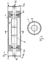
- Fig. 1 and Fig. 2 show a longitudinal or cross section through a roller assembly according to a first embodiment of the present invention.
- the illustrated roller assembly comprises a roller 1 and two rotary bearings 2a, 2b .
- the roller 1 has a reinforcement with a fiber composite material, which is arranged inside the roller 1 .
- the reinforcement is preferably arranged between the rotary bearings 2a, 2b and designed such that the roller 1 is reinforced with respect to a bending load.
- the reinforcement consists in the in Fig. 1 illustrated embodiment of a tube 3 made of a fiber composite material, which rests from the inside to the roller 1 .
- the reinforcement achieves a high rigidity of the roller arrangement, with the roller simultaneously having a relatively low moment of inertia with the reinforcement.
- the roller arrangement or the rotary printing press can be brought to a standstill faster in the event of a malfunction with one or more roller arrangements according to the invention than is the case with roller arrangements according to the prior art, wherein the braking effect is mediated via the paper web.
- the reinforcement minimizes the deflection of the roll, which is generated due to the force of the paper web, so that the paper web is not partially stretched by the deflection. Because at a point with a high deflection, the path that the paper web has to travel is less than at a point with a small deflection.
- the rotary bearings 2a, 2b of the roller assembly are in the embodiment according to Fig. 1 arranged on a fixed axis 8 , which extends over the entire length of the roller.
- the rotary bearings 2a, 2b are arranged at an end region of the roller, ie right and left. With a fixed Axis, the pivot bearings can be supported advantageously, the end point of the axis, which serve to fasten the roller assembly, do not have to absorb bending moments.
- the entire roller arrangement has been optimized in order to achieve the least possible deflection.
- the length of the roller, the position of the rotary bearings, the wall thicknesses of the roller and the reinforcement with fiber composite were taken into account. It was found that the ratio of the distance between the radial line of action of the pivot bearing to the end of the roll over the total length of the roll is advantageously about 0.035.
- the ratio of outer diameter of the roll to the total length of the roll is preferably about 0.54.
- the ratio of the wall thickness of the roller in the area between the pivot bearings relative to the outer diameter of the roller is about 0.03.
- the ratio of the wall thickness of the fiber composite pipe to the wall thickness of the roll in the area between the rotary bearings is about 0.71.
- Roller covers 10a, 10b are preferably respectively arranged at the ends of the axles, an air gap 11 being present between the roller covers 10a, 10b and the roller.
- the air gap runs in the circumferential direction and is in the range of 1.25 mm. The action of the fixed roller cover and the rotating roller prevents dirt from entering the interior of the roller assembly.
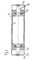
- Fig. 3 shows a longitudinal section through a roller assembly according to a second embodiment of the present invention.
- This embodiment corresponds to the first embodiment except that there is no continuous axis. Instead, the pivot bearings 2a, 2b are arranged on axle sections 9a, 9b , which are separated from one another.
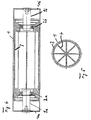
- FIG. 4 and FIG. 5 show a longitudinal or cross section through a roller assembly according to a third embodiment of the present invention.
- This embodiment corresponds to the second embodiment, wherein the reinforcement additionally comprises strips 4 made of a fiber composite material which extend parallel to the roll axis and are arranged radially inside the roll 1.
- the strips extend over the roller center.
- Fig. 6 and Fig. 7 show a longitudinal or cross section through a roller assembly according to a fourth embodiment of the present invention.
- strips 6 are also provided, but do not extend beyond the roller center.
- a further support tube 5 is provided here radially inwardly with respect to the strips 6 in order to support the strips 6 of a fiber composite material from the inside.
- the support tube may also consist of the fiber composite material.
- a tube 3 may be provided in addition, as is the case in the first embodiment.
- FIGS. 8 and 9 show a longitudinal or cross section through a roller assembly according to a fifth embodiment of the present invention.
- This embodiment has as a reinforcement exclusively strips 7 made of fiber composite material, but no tube made of a fiber composite material.
- multifilament carbon fibers or polyacrylonitrile-based fibers can be used, which are preferably carbonized by pyrolysis or refined by graphitization to UltraHochmodul fibers (UHM).
- UHM UltraHochmodul fibers
- the fibers can be embedded in a matrix, in particular in a duroplastic matrix or a resin matrix (typically epoxy resin).
- the course of the fiber directions is preferably in the region of the total reinforcement in the longitudinal direction (with respect to the roller axis).
- the fibers run alternatively or additionally in the angular range of 30-60 ° to the longitudinal direction, and if necessary, are arranged crossed.
- the reinforcement can be introduced in all embodiments in a state when the matrix or the epoxy resin is not yet cured. In this way, a firm bond between the reinforcement and the roller is achieved.
- the reinforcement can also be formed beforehand, and then inserted and glued into the roll.
- the roll assembly is balanced, wherein - if necessary - balancing weights are arranged or glued in the interior of the roll at appropriate locations.
- pivot bearings are shown in the embodiments as a ball bearing. However, plain bearings or air bearings can be used instead.
Landscapes
- Engineering & Computer Science (AREA)
- Mechanical Engineering (AREA)
- Rolls And Other Rotary Bodies (AREA)
- Rotary Presses (AREA)
- Registering, Tensioning, Guiding Webs, And Rollers Therefor (AREA)
Description
- Die vorliegende Erfindung betrifft eine Walzenanordnung, die in Druckmaschinen, insbesondere in Rotationsdruckmaschinen verwendet werden.
- In Rotationsdruckmaschinen werden eine Vielzahl von Umlenkwalzen verwendet, die weder aktiv angetrieben werden, noch aktiv abgebremst werden können. Im Falle eines Störungsfalles (z.B. im Falle eines Papierrisses) muss die Rotationsdruckmaschine angehalten werden. Da eine Rotationsdruckmaschine oft bei relative hohen Papierlaufgeschwindigkeiten betrieben wird (z.B. 1000 m/min bzw. 18 m/sec), dauert der Abbremsvorgang relativ lange, und der Papierausschuss ist beträchtlich (teils über 100 m Papierband).
- Im Stand der Technik z.B. aus den Schriften
DE 29801421-U1 , DE 20321351-U1 oderDE4125620-A1 sind verschiedene Konstruktionen für Walzenanordnungen bekannt, die in Druckmaschinen, insbesondere in Rotationsdruckmaschinen verwendet werden. - Eine Walzenanordnung weist eine Walze und zwei Drehlagerungen auf. Erfindungsgemäß ist vorgesehen, dass die Walze eine Verstärkung mit einem Faserverbundwerkstoff aufweist, die innerhalb der Walze angeordnet ist, wobei das Verhältnis von Abstand der radialen Wirkungslinie der Drehlagerung zum Walzenende gegenüber der Gesamtlänge der Walze im Bereich von 0,015 bis 0,05 liegt. Die Verstärkung ist vorzugsweise zwischen den Drehlagerungen angeordnet und derart ausgestaltet, dass die Walze gegenüber einer Biegebelastung verstärkt ist.
- Die Verstärkung mit einem Faserverbundwerkstoff kann verschiedene Ausgestaltungen aufweisen. So kann die Verstärkung ein Rohr aus einem Faserverbundwerkstoff aufweisen, welches von Innen an der Walze anliegt. Alternativ oder zusätzlich kann die Verstärkung Leisten aus einem Faserverbundwerkstoff aufweisen, welche parallel zur Walzenachse verlaufen und innerhalb der Walze radial angeordnet sind. Sofern Leisten verwendet werden, kann zusätzlich ein Stützrohr vorgesehen werden, um die Leisten aus einem Faserverbundwerkstoff von Innen abzustützen.
- Durch die Verstärkung mit einem Faserverbundwerkstoff wird eine hohe Steifigkeit der Walzenanordnung erreicht, wobei die Walze mit der Verstärkung gleichzeitig ein relativ geringes Trägheitsmoment aufweist. Dadurch kann die Walzenanordnung bzw. die Rotationsdruckmaschine mit einer oder mehreren erfindungsgemäßen Walzenanordnungen im Störungsfall schneller zum Stillstand gebracht werden, als dies bei Walzenanordnungen nach dem Stand der Technik der Fall ist, wobei die Bremswirkung über die Papierbahn vermittelt wird.
- Erfindungsgemäß wird durch die Verstärkung außerdem die Durchbiegung der Walze, die aufgrund der Kraft der Papierbahn erzeugt wird, minimiert, damit die Papierbahn durch die Umlenkung nicht partiell gedehnt wird. Denn an einer Stelle mit einer hohen Durchbiegung ist der Weg, den die Papierbahn zurücklegen muss geringer als an einer Stelle mit einer geringen Durchbiegung.
- Die Drehlagerungen der Walzenanordnung können auf einer (feststehenden) Achse angeordnet sein, welche sich über die gesamte Länge der Walze erstreckt. Die Drehlagerungen sind dabei vorzugsweise an einem Endbereich der Walze angeordnet. Mit einer feststehenden Achse können die Drehlagerungen vorteilhaft abgestützt werden, wobei die Endpunkt der Achse, welche zur Befestigung der Walzenanordnung dienen, keine Biegemomente aufnehmen müssen.
- Alternativ können die Drehlagerungen auf Achsabschnitten angeordnet sind, welche voneinander getrennt sind. Dies hat zwar den Nachteil, dass die Montage eventuell aufwendiger ist, und dass die Achsabschnitte auch Biegemomente aufnehmen müssen. Jedoch hat dies den Vorteil, dass sich die Leisten der Verstärkung, die sich gemeinsam mit der Walze im Betrieb drehen, über den Mittelpunkt hinweg erstrecken können, da keine durchgehende feststehene Achse im Wege steht.
- Erfindungsgemäß wurde die gesamte Walzenanordnung optimiert, um eine möglichst minimale Durchbiegung zu erreichen. Dabei wurden die Länge der Walze, die Position der Drehlagerungen, die Wanddicken der Walze und der Verstärkung mit Faserverbundwerkstoff berücksichtigt. Dabei wurde festgestellt, dass das Verhältnis von Abstand der radialen Wirkungslinie der Drehlagerung zum Walzenende gegenüber der Gesamtlänge der Walze vorteilhaft im Bereich von 0,015 bis 0.05 liegt, insbesondere von 0,03 bis 0,04, insbesondere etwa oder genau 0,035 liegt. Das Verhältnis von Außendurchmesser der Walze gegenüber der Gesamtlänge der Walze liegt vorzugsweise im Bereich von 0,03 bis 0,1, insbesondere von 0.04 bis 0.7, insbesondere etwa 0,05 bis 0.06, vorzugsweise etwa oder genau 0,54. Das Verhältnis der Wanddicke der Walze im Bereich zwischen den Drehlagerungen gegenüber dem Außendurchmesser der Walze liegt im Bereich von 0,01 bis 0.08, insbesondere von 0,02 bis 0,06, insbesondere etwa 0,015 bis 0,04, vorzugsweise etwa oder genau 0,03. Das Verhältnis der Wanddicke des Rohres aus Faserverbundwerkstoff gegenüber der Wanddicke der Walze im Bereich zwischen den Drehlagerungen liegt im Bereich von 0,2 bis 1,0, insbesondere von 0,5 bis 0,9, insbesondere etwa 0,6 bis 0,8, vorzugsweise etwa oder genau 0,71.
- An den Enden der Achsen sind vorzugsweise jeweils Walzendeckel angeordnet, wobei zwischen den Walzendeckeln und der Walze ein Luftspalt vorhanden ist. Der Luftspalt verläuft in Umfangsrichtung und liegt im Bereich von 0,3 bis 2 mm, insbesondere im Bereich von 0,5 bis 1,8 mm, insbesondere im Bereich von 0,9 bis 1,4 mm, vorzugsweise etwa oder genau 1,25 mm. Durch die Wirkung der feststehenden Walzendeckel und der rotierenden Walze wird ein Eindringen von Schmutz in das Innere der Walzenanordnung verhindert.
- Als Materialien für die Verstärkung aus Faserverbundwerkstoff können beispielsweise Multifilament-Carbonfasern oder Fasern auf Polyacrylnitril-Basis verwendet werden, die vorzugsweise durch Pyrolyse karbonisiert oder durch Graphitierung zu UltraHochModul-Fasern (UHM) veredelt werden. Die Fasern können in eine Matrix eingebettet werden, insbesondere in eine duroplastische Matrix bzw. eine Harz-Matrix (typischerweise Epoxidharz).
- Der Verlauf der Faserrichtungen ist im Bereich der gesamten Verstärkung vorzugsweise in Längsrichtung (in Bezug auf die Walzenachse). Bei Verwendung von Leisten ist es jedoch auch möglich, dass die Fasern alternativ oder zusätzlich im Winkelbereich von 30 - 60° zur Längsrichtung verlaufen, und ggfs. gekreuzt angeordnet sind.
-
- Fig. 1
- zeigt einen Längsschnitt durch eine Walzenanordnung nach einer ersten Ausführungsform der vorliegenden Erfindung;
- Fig. 2
- zeigt einen Querschnitt durch eine Walzenanordnung nach der in
Fig. 1 dargestellten Ausführungsform; - Fig. 3
- zeigt einen Längsschnitt durch eine Walzenanordnung nach einer zweiten Ausführungsform der vorliegenden Erfindung;
- Fig. 4
- zeigt einen Längsschnitt durch eine Walzenanordnung nach einer dritten Ausführungsform der vorliegenden Erfindung;
- Fig. 5
- zeigt einen Querschnitt durch eine Walzenanordnung nach der in
Fig. 4 dargestellten Ausführungsform; - Fig. 6
- zeigt einen Längsschnitt durch eine Walzenanordnung nach einer vierten Ausführungsform der vorliegenden Erfindung;
- Fig. 7
- zeigt einen Querschnitt durch eine Walzenanordnung nach der in
Fig. 6 dargestellten Ausführungsform; - Fig. 8
- zeigt einen Längsschnitt durch eine Walzenanordnung nach einer fünften Ausführungsform der vorliegenden Erfindung;
- Fig. 9
- zeigt einen Querschnitt durch eine Walzenanordnung nach der in
Fig. 8 dargestellten Ausführungsform. -
Fig. 1 und Fig. 2 zeigen einen Längs- bzw. Querschnitt durch eine Walzenanordnung nach einer ersten Ausführungsform der vorliegenden Erfindung. Die dargestellte Walzenanordnung weist eine Walze 1 und zwei Drehlagerungen 2a, 2b auf. Erfindungsgemäß ist vorgesehen, dass die Walze 1 eine Verstärkung mit einem Faserverbundwerkstoff aufweist, die innerhalb der Walze 1 angeordnet ist. Die Verstärkung ist vorzugsweise zwischen den Drehlagerungen 2a, 2b angeordnet und derart ausgestaltet, dass die Walze 1 gegenüber einer Biegebelastung verstärkt ist. - Die Verstärkung besteht in der in
Fig. 1 dargestellten Ausführungsform aus einem Rohr 3 aus einem Faserverbundwerkstoff, welches von Innen an der Walze 1 anliegt. Wie bereits ausgeführt, wird durch die Verstärkung eine hohe Steifigkeit der Walzenanordnung erreicht, wobei die Walze mit der Verstärkung gleichzeitig ein relativ geringes Trägheitsmoment aufweist. Dadurch kann die Walzenanordnung bzw. die Rotationsdruckmaschine mit einer oder mehreren erfindungsgemäßen Walzenanordnungen im Störungsfall schneller zum Stillstand gebracht werden, als dies bei Walzenanordnungen nach dem Stand der Technik der Fall ist, wobei die Bremswirkung über die Papierbahn vermittelt wird. Außerdem wird durch die Verstärkung die Durchbiegung der Walze, die aufgrund der Kraft der Papierbahn erzeugt wird, minimiert, damit die Papierbahn durch die Umlenkung nicht partiell gedehnt wird. Denn an einer Stelle mit einer hohen Durchbiegung ist der Weg, den die Papierbahn zurücklegen muss geringer als an einer Stelle mit einer geringen Durchbiegung. - Die Drehlagerungen 2a, 2b der Walzenanordnung sind bei der Ausführungsform nach
Fig. 1 auf einer feststehenden Achse 8 angeordnet, welche sich über die gesamte Länge der Walze erstreckt. Die Drehlagerungen 2a, 2b sind dabei an einem Endbereich der Walze, d.h. rechts und links angeordnet. Mit einer feststehenden Achse können die Drehlagerungen vorteilhaft abgestützt werden, wobei die Endpunkt der Achse, welche zur Befestigung der Walzenanordnung dienen, keine Biegemomente aufnehmen müssen. - Erfindungsgemäß wurde die gesamte Walzenanordnung optimiert, um eine möglichst minimale Durchbiegung zu erreichen. Dabei wurden die Länge der Walze, die Position der Drehlagerungen, die Wanddicken der Walze und der Verstärkung mit Faserverbundwerkstoff berücksichtigt. Dabei wurde festgestellt, dass das Verhältnis von Abstand der radialen Wirkungslinie der Drehlagerung zum Walzenende gegenüber der Gesamtlänge der Walze vorteilhaft bei etwa 0,035 liegt. Das Verhältnis von Außendurchmesser der Walze gegenüber der Gesamtlänge der Walze liegt vorzugsweise bei etwa 0,54. Das Verhältnis der Wanddicke der Walze im Bereich zwischen den Drehlagerungen gegenüber dem Außendurchmesser der Walze liegt bei etwa 0,03. Das Verhältnis der Wanddicke des Rohres aus Faserverbundwerkstoff gegenüber der Wanddicke der Walze im Bereich zwischen den Drehlagerungen liegt bei etwa 0,71.
- An den Enden der Achsen sind vorzugsweise jeweils Walzendeckel 10a, 10b angeordnet, wobei zwischen den Walzendeckeln 10a, 10b und der Walze ein Luftspalt 11 vorhanden ist. Der Luftspalt verläuft in Umfangsrichtung und liegt im Bereich von 1,25 mm. Durch die Wirkung der feststehenden Walzendeckel und der rotierenden Walze wird ein Eindringen von Schmutz in das Innere der Walzenanordnung verhindert.
-
Fig. 3 zeigt einen Längsschnitt durch eine Walzenanordnung nach einer zweiten Ausführungsform der vorliegenden Erfindung. Diese Ausführungsform entspricht der ersten Ausführungsform mit der Ausnahme, dass keine durchgehende Achse vorhanden ist. Stattdessen sind die Drehlagerungen 2a, 2b auf Achsabschnitten 9a, 9b angeordnet, welche voneinander getrennt sind. -
Fig. 4 und Fig. 5 zeigen einen Längs- bzw. Querschnitt durch eine Walzenanordnung nach einer dritten Ausführungsform der vorliegenden Erfindung. Diese Ausführungsform entspricht der zweiten Ausführungsform, wobei die Verstärkung zusätzlich Leisten 4 aus einem Faserverbundwerkstoff aufweist, welche parallel Walzenachse verlaufen und innerhalb der Walze 1 radial angeordnet sind. Wie inFig. 5 dargestellt ist, erstrecken sich die Leisten über den Walzenmittelpunkt. Wie bereits ausgeführt, hat zwar den Nachteil, dass die Montage eventuell aufwendiger ist, und dass die Achsabschnitte auch Biegemomente aufnehmen müssen, da keine durchgehende Achse vorhanden ist. Jedoch hat dies den Vorteil, dass sich die Leisten 4, die sich gemeinsam mit der Walze im Betrieb drehen, eine sehr hohe Versteifungswirkung haben. -
Fig. 6 und Fig. 7 zeigen einen Längs- bzw. Querschnitt durch eine Walzenanordnung nach einer vierten Ausführungsform der vorliegenden Erfindung. In dieser Ausführungsform sind ebenfalls Leisten 6 vorgesehen, die sich jedoch nicht über den Walzenmittelpunkt hinweg erstrecken. Zur Versteifung ist hier radial innenliegend in Bezug auf die Leisten 6 ein weiteres Stützrohr 5 vorgesehen, um die Leisten 6 aus einem Faserverbundwerkstoff von Innen abzustützen. Das Stützrohr kann ebenfalls aus dem Faserverbundwerkstoff bestehen. Außerdem kann zusätzlich auch ein Rohr 3 vorgesehen werden, wie dies bei der ersten Ausführungsform der Fall ist. -
Fig. 8 und Fig. 9 zeigen einen Längs- bzw. Querschnitt durch eine Walzenanordnung nach einer fünften Ausführungsform der vorliegenden Erfindung. Diese Ausführungsform weist als Verstärkung ausschließlich Leisten 7 aus Faserverbundwerkstoff auf, jedoch kein Rohr aus einem Faserverbundwerkstoff. - Als Materialien für die Verstärkung aus Faserverbundwerkstoff können beispielsweise Multifilament-Carbonfasern oder Fasern auf Polyacrylnitril-Basis verwendet werden, die vorzugsweise durch Pyrolyse karbonisiert oder durch Graphitierung zu UltraHochmodul-Fasern (UHM) veredelt werden. Die Fasern können in eine Matrix eingebettet werden, insbesondere in eine duroplastische Matrix bzw. eine Harz-Matrix (typischerweise Epoxidharz).
- Der Verlauf der Faserrichtungen ist im Bereich der gesamten Verstärkung vorzugsweise in Längsrichtung (in Bezug auf die Walzenachse). Bei Verwendung von Leisten ist es jedoch auch möglich, dass die Fasern alternativ oder zusätzlich im Winkelbereich von 30 - 60° zur Längsrichtung verlaufen, und ggfs. gekreuzt angeordnet sind.
- Die Verstärkung kann bei allen Ausführungsbeispielen in einem Zustand eingebracht werden, wenn die Matrix bzw. das Epoxidharz noch nicht ausgehärtet ist. Auf diese Weise wird ein fester Verbund zwischen der Verstärkung und der Walze erreicht. Alternativ kann die Verstärkung auch vorher ausgeformt werden, und anschließend in die Walze eingeschoben und eingeklebt werden.
- Nach der Montage wird die Walzenanordnung gewuchtet, wobei - sofern erforderlich - Ausgleichsgewichte im Walzeninneren an geeigneten Stellen angeordnet bzw. angeklebt werden.
- Die Drehlager sind in den Ausführungsbeispielen als Kugellager dargestellt. Es können jedoch stattdessen auch Gleitlager oder Luftlager verwendet werden.
Claims (14)
- Walzenanordnung mit einer Walze (1) und zwei Drehlagerungen (2a, 2b), wobei die Walze (1) eine Verstärkung mit einem Faserverbundwerkstoff aufweist, die innerhalb der Walze (1) angeordnet ist,
dadurch gekennzeichnet, dass das Verhältnis von Abstand der radialen Wirkungslinie der Drehlagerung zum Walzenende gegenüber der Gesamtlänge der Walze im Bereich von 0,015 bis 0,05 liegt. - Walzenanordnung nach Patenanspruch 1, dadurch gekennzeichnet, dass das Verhältnis von Abstand der radialen Wirkungslinie der Drehlagerung zum Walzenende gegenüber der Gesamtlänge der Walze im Bereich von 0,03 bis 0,04 liegt.
- Walzenanordnung nach Patenanspruch 1, dadurch gekennzeichnet, dass das Verhältnis von Abstand der radialen Wirkungslinie der Drehlagerung zum Walzenende gegenüber der Gesamtlänge der Walze etwa oder genau 0,035 ist.
- Walzenanordnung nach einem der Patentansprüche 1 bis 3, dadurch gekennzeichnet, dass die Verstärkung mit einem Faserverbundwerkstoff zwischen den Drehlagerungen (2a, 2b) angeordnet ist und derart ausgestaltet ist, dass die Walze (1) gegenüber einer Biegebelastung verstärkt ist.
- Walzenanordnung nach einem der Patentansprüche 1 bis 4, dadurch gekennzeichnet, dass die Verstärkung ein Rohr (3) aus einem Faserverbundwerkstoff aufweist, welches von Innen an der Walze (1) anliegt.
- Walzenanordnung nach einem der vorhergehenden Patentansprüche, dadurch gekennzeichnet, dass die Drehlagerungen (2a, 2b) auf einer Achse (8) angeordnet sind, welche über die gesamte Länge der Walze erstreckt
- Walzenanordnung nach einem der Patentansprüche 1 bis 5, dadurch gekennzeichnet, dass die Drehlagerungen (2a, 2b) auf Achsabschnitten (9a, 9b) angeordnet sind, welche voneinander getrennt sind.
- Walzenanordnung nach einem der vorhergehenden Patentansprüche, dadurch gekennzeichnet, dass jeweils eine Drehlagerung (2a; 2b) an einem Endbereich der Walze angeordnet ist.
- Walzenanordnung nach einem der vorhergehenden Patentansprüche, dadurch gekennzeichnet, dass das Verhältnis von Außendurchmesser der Walze gegenüber der Gesamtlänge der Walze im Bereich von 0,03 bis 0,1 liegt, insbesondere von 0,04 bis 0,07 insbesondere etwa 0,05 bis 0,06.
- Walzenanordnung nach einem der vorhergehenden Patentansprüche, dadurch gekennzeichnet, dass das Verhältnis der Wanddicke der Walze im Bereich zwischen den Drehlagerungen gegenüber dem Außendurchmesser der Walze im Bereich von 0,01 bis 0,08 liegt, insbesondere von 0,02 bis 0,06, insbesondere etwa 0,015 bis 0,04.
- Walzenanordnung nach einem der Patentansprüche 5 bis 10, dadurch gekennzeichnet, dass das Verhältnis der Wanddicke des Rohres aus Faserverbundwerkstoff gegenüber der Wanddicke der Walze im Bereich zwischen den Drehlagerungen im Bereich von 0,2 bis 1,0 liegt, insbesondere von 0,5 bis 0,9, insbesondere etwa 0,6 bis 0,8.
- Walzenanordnung nach einem der Patentansprüche 7 bis 11, dadurch gekennzeichnet, dass an den Enden der Achsen jeweils Walzendeckel (10a, 10b) angeordnet sind, wobei zwischen den Walzendeckeln (10a, 10b) und der Walze ein Luftspalt (11) vorhanden ist.
- Walzenanordnung nach Patentanspruch 12 dadurch gekennzeichnet, dass der Luftspalt in Umfangsrichtung verläuft und im Bereich von 0,3 bis 2 mm liegt, insbesondere im Bereich von 0,5 bis 1,8 mm, insbesondere im Bereich von 0,9 bis 1,4 mm.
- Druckmaschine, insbesondere Rotationsdruckmaschine, gekennzeichnet durch eine oder mehrere Walzenanordnungen nach einem der vorhergehenden Patentansprüche.
Priority Applications (6)
| Application Number | Priority Date | Filing Date | Title |
|---|---|---|---|
| EP09165302A EP2275372B1 (de) | 2009-07-13 | 2009-07-13 | Leichtlaufwalze |
| ES09165302T ES2386932T3 (es) | 2009-07-13 | 2009-07-13 | Rodillo de marcha fácil |
| US12/824,276 US20110005414A1 (en) | 2009-07-13 | 2010-06-28 | Low Friction Roll |
| JP2010146202A JP5656473B2 (ja) | 2009-07-13 | 2010-06-28 | 印刷機用ロールアセンブリ |
| CA2709113A CA2709113C (en) | 2009-07-13 | 2010-07-07 | Fiber composite reinforced printing roll |
| CN201010231325.2A CN101954778B (zh) | 2009-07-13 | 2010-07-13 | 低摩擦辊及具有该辊的印刷机 |
Applications Claiming Priority (1)
| Application Number | Priority Date | Filing Date | Title |
|---|---|---|---|
| EP09165302A EP2275372B1 (de) | 2009-07-13 | 2009-07-13 | Leichtlaufwalze |
Publications (2)
| Publication Number | Publication Date |
|---|---|
| EP2275372A1 EP2275372A1 (de) | 2011-01-19 |
| EP2275372B1 true EP2275372B1 (de) | 2012-05-30 |
Family
ID=40902883
Family Applications (1)
| Application Number | Title | Priority Date | Filing Date |
|---|---|---|---|
| EP09165302A Active EP2275372B1 (de) | 2009-07-13 | 2009-07-13 | Leichtlaufwalze |
Country Status (6)
| Country | Link |
|---|---|
| US (1) | US20110005414A1 (de) |
| EP (1) | EP2275372B1 (de) |
| JP (1) | JP5656473B2 (de) |
| CN (1) | CN101954778B (de) |
| CA (1) | CA2709113C (de) |
| ES (1) | ES2386932T3 (de) |
Families Citing this family (4)
| Publication number | Priority date | Publication date | Assignee | Title |
|---|---|---|---|---|
| DE102010015108A1 (de) * | 2010-04-16 | 2011-10-20 | Goebel Gmbh | Rotationszylinder für eine Verarbeitungsmaschine |
| DE202011003940U1 (de) * | 2011-03-14 | 2012-06-15 | Texmag Gmbh Vertriebsgesellschaft | Walze |
| EP2524805A1 (de) * | 2011-05-20 | 2012-11-21 | KBA-NotaSys SA | Tintenwischsystem für eine Intaglio-Druckpresse |
| US10450480B2 (en) * | 2013-03-13 | 2019-10-22 | Hentzen Coatings, Inc. | Water-reducible single-component moisture-curing polyurethane coatings |
Family Cites Families (32)
| Publication number | Priority date | Publication date | Assignee | Title |
|---|---|---|---|---|
| US3808657A (en) * | 1972-01-26 | 1974-05-07 | Marathon Rollers Inc | Hickey roll and method of making same |
| CH643796A5 (de) * | 1980-04-11 | 1984-06-29 | Sig Schweiz Industrieges | Umlenkrolle fuer bahnfoermiges, blattartiges material. |
| US4339858A (en) * | 1980-11-03 | 1982-07-20 | Minnesota Mining And Manufacturing Company | Dampener roll cover |
| JPH0342254Y2 (de) * | 1986-10-27 | 1991-09-04 | ||
| FR2635718A1 (fr) * | 1988-08-23 | 1990-03-02 | Francille Jean | Cylindre notamment d'imprimerie |
| IT1248446B (it) * | 1990-12-19 | 1995-01-19 | Componenti Grafici Srl | Rullo pressore per macchina da stampa, con sistema di condizionamento e di lubrificazione ad olio |
| DE4109438C2 (de) * | 1991-03-22 | 2001-12-20 | Koenig & Bauer Ag | Farbheber für Druckmaschinen |
| DE4125620C2 (de) * | 1991-08-02 | 1995-04-20 | Roland Man Druckmasch | Montagevorrichtung für eine Walze, insbesondere Papierleitwalze |
| JP3190463B2 (ja) * | 1992-12-28 | 2001-07-23 | 中部ベアリング株式会社 | ローラコンベア用ベアリング |
| JPH0676247U (ja) * | 1993-04-06 | 1994-10-28 | 西研グラフィックス株式会社 | 印刷機用ガイドローラ |
| DE19524707C2 (de) * | 1995-07-10 | 2001-03-01 | Polywest Kunststofftechnik | Verfahren zur Herstellung einer nahtlosen Druckhülse, insbesondere für einen Flexodruckzylinder |
| DE29609007U1 (de) * | 1996-05-20 | 1996-07-04 | MAN Roland Druckmaschinen AG, 63075 Offenbach | Walze für eine Druckmaschine |
| US5857950A (en) * | 1996-11-06 | 1999-01-12 | Pamarco Incorporated | Fluid metering roll |
| DE29701547U1 (de) * | 1997-01-30 | 1997-03-20 | Voith Sulzer Papiermaschinen GmbH, 89522 Heidenheim | Walze für Auftragseinrichtung |
| US5894796A (en) * | 1997-08-01 | 1999-04-20 | Heidelberger Druckmaschinen Ag | Printing unit for a web-fed rotary printing press |
| DE29801421U1 (de) * | 1998-01-29 | 1999-05-27 | L. Blömker GmbH, 49536 Lienen | Rohrförmiger Walzenkörper |
| US6311615B1 (en) * | 1998-07-14 | 2001-11-06 | Heidelberger Druckmaschinen Ag | Composite nip roll and nip ring |
| DE59900456D1 (de) * | 1999-02-01 | 2002-01-10 | Fischer & Krecke Gmbh & Co | Druckplattenzylinder |
| DE19955099B4 (de) * | 1999-11-16 | 2010-02-11 | Maschinenfabrik Wifag | Rotationskörpergebilde für eine Bahnbreitenkorrektur |
| DE19956949C2 (de) * | 1999-11-26 | 2003-05-28 | Koenig & Bauer Ag | Lagerung eines Formzylinders einer Rotationsdruckmaschine |
| JP2002012313A (ja) * | 2000-06-30 | 2002-01-15 | Sanwa Koki Kk | ベルトコンベア用ローラ,ベルトコンベア用ローラの製造方法及びベルトコンベア用ローラの製造用カシメ装置 |
| JP4073402B2 (ja) * | 2002-02-01 | 2008-04-09 | ケーニツヒ ウント バウエル アクチエンゲゼルシヤフト | 回転する構成部分における振動を減少させるための方法および装置 |
| US6799510B2 (en) * | 2002-05-02 | 2004-10-05 | New Hudson Corporation | Thin-walled bridge mandrel |
| DE20321351U1 (de) * | 2003-09-26 | 2006-10-26 | Koenig & Bauer Aktiengesellschaft | Walze eines Farb- oder Feuchtwerks einer Druckmaschine |
| EP1584483A1 (de) * | 2004-04-06 | 2005-10-12 | Riso Kagaku Corporation | Schablonendruckmaschine |
| JP2006023701A (ja) * | 2004-06-09 | 2006-01-26 | Bridgestone Corp | 現像ローラおよびそれを用いた画像形成装置 |
| EP1808293A1 (de) * | 2006-01-13 | 2007-07-18 | Fischer & Krecke GmbH & Co. KG | Druckzylinder für Flexodruck |
| KR101287529B1 (ko) * | 2006-10-27 | 2013-07-19 | 삼성전자주식회사 | 화상형성장치와 그 제조방법 |
| JP2008138735A (ja) * | 2006-11-30 | 2008-06-19 | Bridgestone Corp | 導電性ローラ |
| US8413580B2 (en) * | 2007-12-21 | 2013-04-09 | Day International, Inc. | Compressible printing sleeve carrier and method of making |
| US20090165662A1 (en) * | 2007-12-31 | 2009-07-02 | Nim-Cor, Inc. | Bridge mandrels for anilox and print roller applications and techniques for making them |
| US20090193991A1 (en) * | 2008-02-04 | 2009-08-06 | Felice Rossini | Blanket sleeve and cylinder and method of making same |
-
2009
- 2009-07-13 EP EP09165302A patent/EP2275372B1/de active Active
- 2009-07-13 ES ES09165302T patent/ES2386932T3/es active Active
-
2010
- 2010-06-28 JP JP2010146202A patent/JP5656473B2/ja active Active
- 2010-06-28 US US12/824,276 patent/US20110005414A1/en not_active Abandoned
- 2010-07-07 CA CA2709113A patent/CA2709113C/en not_active Expired - Fee Related
- 2010-07-13 CN CN201010231325.2A patent/CN101954778B/zh active Active
Also Published As
| Publication number | Publication date |
|---|---|
| JP2011021746A (ja) | 2011-02-03 |
| CN101954778A (zh) | 2011-01-26 |
| CA2709113A1 (en) | 2011-01-13 |
| EP2275372A1 (de) | 2011-01-19 |
| CA2709113C (en) | 2014-06-17 |
| ES2386932T3 (es) | 2012-09-06 |
| US20110005414A1 (en) | 2011-01-13 |
| CN101954778B (zh) | 2013-03-06 |
| JP5656473B2 (ja) | 2015-01-21 |
Similar Documents
| Publication | Publication Date | Title |
|---|---|---|
| EP1025996B1 (de) | Druckplattenzylinder | |
| EP2275372B1 (de) | Leichtlaufwalze | |
| EP2743058B1 (de) | Strukturintegrierte Verstärkung in gewickelten Bauteilen aus Verbundwerkstoffen | |
| EP0543959B1 (de) | Verfahren zur herstellung eines mehrlagigen kartons | |
| EP3670718B1 (de) | Ringspinnmaschine mit streckwerken | |
| EP1586703B1 (de) | Walze zur Behandlung flacher Materialien und Verfahren zur Herstellung dieser Walze | |
| DE19940424A1 (de) | Walze | |
| EP1735157A2 (de) | Druckformzylinder mit einer kohlefasern enthaltenden kunststoffhülse | |
| DE2847587A1 (de) | Getriebe | |
| EP2743063B1 (de) | Strukturintegrierte Verstärkung in gewickelten Bauteilen aus Verbundwerkstoffen | |
| EP2905365B1 (de) | Baugruppe einer Kettenwirkmaschine | |
| DE202009012298U1 (de) | Leitwalze | |
| WO2017215853A1 (de) | Walzenvorrichtung | |
| DE19952320A1 (de) | Elastische Walze sowie Verfahren zur Herstellung einer solchen Walze | |
| DE102007059073A1 (de) | Rollenpresse mit symmetrischer Walzenzentrierung | |
| EP3307665A1 (de) | Wickelwelle zur aufnahme von wenigstens einer wickelhülse | |
| DE10300404A1 (de) | Aufspulvorrichtung | |
| DE102012203101A1 (de) | Walze | |
| EP4296414A1 (de) | Vorrichtung zur kalandrierung einer wattebahn | |
| EP4522420A1 (de) | Antriebsvorrichtung für eine exzenterlagerung sowie ein entsprechender kalander | |
| DE102008002255A1 (de) | Walze | |
| EP3879015A1 (de) | Vorrichtung zur drehmomentübertragung | |
| EP0366690A1 (de) | Verfahren zum aufbringen eines nichtmetallischen walzenbezuges | |
| DE102008002112A1 (de) | Biegeeinstellwalze | |
| EP1970488A1 (de) | Pressenanordnung |
Legal Events
| Date | Code | Title | Description |
|---|---|---|---|
| PUAI | Public reference made under article 153(3) epc to a published international application that has entered the european phase |
Free format text: ORIGINAL CODE: 0009012 |
|
| AK | Designated contracting states |
Kind code of ref document: A1 Designated state(s): AT BE BG CH CY CZ DE DK EE ES FI FR GB GR HR HU IE IS IT LI LT LU LV MC MK MT NL NO PL PT RO SE SI SK SM TR |
|
| 17P | Request for examination filed |
Effective date: 20110203 |
|
| 17Q | First examination report despatched |
Effective date: 20110221 |
|
| GRAP | Despatch of communication of intention to grant a patent |
Free format text: ORIGINAL CODE: EPIDOSNIGR1 |
|
| GRAS | Grant fee paid |
Free format text: ORIGINAL CODE: EPIDOSNIGR3 |
|
| GRAA | (expected) grant |
Free format text: ORIGINAL CODE: 0009210 |
|
| AK | Designated contracting states |
Kind code of ref document: B1 Designated state(s): AT BE BG CH CY CZ DE DK EE ES FI FR GB GR HR HU IE IS IT LI LT LU LV MC MK MT NL NO PL PT RO SE SI SK SM TR |
|
| REG | Reference to a national code |
Ref country code: GB Ref legal event code: FG4D Free format text: NOT ENGLISH |
|
| REG | Reference to a national code |
Ref country code: CH Ref legal event code: EP |
|
| REG | Reference to a national code |
Ref country code: AT Ref legal event code: REF Ref document number: 559984 Country of ref document: AT Kind code of ref document: T Effective date: 20120615 |
|
| REG | Reference to a national code |
Ref country code: IE Ref legal event code: FG4D Free format text: LANGUAGE OF EP DOCUMENT: GERMAN |
|
| REG | Reference to a national code |
Ref country code: DE Ref legal event code: R096 Ref document number: 502009003663 Country of ref document: DE Effective date: 20120726 |
|
| REG | Reference to a national code |
Ref country code: ES Ref legal event code: FG2A Ref document number: 2386932 Country of ref document: ES Kind code of ref document: T3 Effective date: 20120906 |
|
| REG | Reference to a national code |
Ref country code: NL Ref legal event code: VDEP Effective date: 20120530 |
|
| REG | Reference to a national code |
Ref country code: LT Ref legal event code: MG4D Effective date: 20120530 |
|
| PG25 | Lapsed in a contracting state [announced via postgrant information from national office to epo] |
Ref country code: LT Free format text: LAPSE BECAUSE OF FAILURE TO SUBMIT A TRANSLATION OF THE DESCRIPTION OR TO PAY THE FEE WITHIN THE PRESCRIBED TIME-LIMIT Effective date: 20120530 Ref country code: CY Free format text: LAPSE BECAUSE OF FAILURE TO SUBMIT A TRANSLATION OF THE DESCRIPTION OR TO PAY THE FEE WITHIN THE PRESCRIBED TIME-LIMIT Effective date: 20120530 Ref country code: NO Free format text: LAPSE BECAUSE OF FAILURE TO SUBMIT A TRANSLATION OF THE DESCRIPTION OR TO PAY THE FEE WITHIN THE PRESCRIBED TIME-LIMIT Effective date: 20120830 Ref country code: FI Free format text: LAPSE BECAUSE OF FAILURE TO SUBMIT A TRANSLATION OF THE DESCRIPTION OR TO PAY THE FEE WITHIN THE PRESCRIBED TIME-LIMIT Effective date: 20120530 Ref country code: IS Free format text: LAPSE BECAUSE OF FAILURE TO SUBMIT A TRANSLATION OF THE DESCRIPTION OR TO PAY THE FEE WITHIN THE PRESCRIBED TIME-LIMIT Effective date: 20120930 Ref country code: SE Free format text: LAPSE BECAUSE OF FAILURE TO SUBMIT A TRANSLATION OF THE DESCRIPTION OR TO PAY THE FEE WITHIN THE PRESCRIBED TIME-LIMIT Effective date: 20120530 |
|
| PG25 | Lapsed in a contracting state [announced via postgrant information from national office to epo] |
Ref country code: LV Free format text: LAPSE BECAUSE OF FAILURE TO SUBMIT A TRANSLATION OF THE DESCRIPTION OR TO PAY THE FEE WITHIN THE PRESCRIBED TIME-LIMIT Effective date: 20120530 Ref country code: SI Free format text: LAPSE BECAUSE OF FAILURE TO SUBMIT A TRANSLATION OF THE DESCRIPTION OR TO PAY THE FEE WITHIN THE PRESCRIBED TIME-LIMIT Effective date: 20120530 Ref country code: GR Free format text: LAPSE BECAUSE OF FAILURE TO SUBMIT A TRANSLATION OF THE DESCRIPTION OR TO PAY THE FEE WITHIN THE PRESCRIBED TIME-LIMIT Effective date: 20120831 Ref country code: HR Free format text: LAPSE BECAUSE OF FAILURE TO SUBMIT A TRANSLATION OF THE DESCRIPTION OR TO PAY THE FEE WITHIN THE PRESCRIBED TIME-LIMIT Effective date: 20120530 |
|
| BERE | Be: lapsed |
Owner name: TEXMAG GMBH VERTRIEBSGESELLSCHAFT Effective date: 20120731 |
|
| PG25 | Lapsed in a contracting state [announced via postgrant information from national office to epo] |
Ref country code: NL Free format text: LAPSE BECAUSE OF FAILURE TO SUBMIT A TRANSLATION OF THE DESCRIPTION OR TO PAY THE FEE WITHIN THE PRESCRIBED TIME-LIMIT Effective date: 20120530 Ref country code: SK Free format text: LAPSE BECAUSE OF FAILURE TO SUBMIT A TRANSLATION OF THE DESCRIPTION OR TO PAY THE FEE WITHIN THE PRESCRIBED TIME-LIMIT Effective date: 20120530 Ref country code: RO Free format text: LAPSE BECAUSE OF FAILURE TO SUBMIT A TRANSLATION OF THE DESCRIPTION OR TO PAY THE FEE WITHIN THE PRESCRIBED TIME-LIMIT Effective date: 20120530 Ref country code: DK Free format text: LAPSE BECAUSE OF FAILURE TO SUBMIT A TRANSLATION OF THE DESCRIPTION OR TO PAY THE FEE WITHIN THE PRESCRIBED TIME-LIMIT Effective date: 20120530 Ref country code: CZ Free format text: LAPSE BECAUSE OF FAILURE TO SUBMIT A TRANSLATION OF THE DESCRIPTION OR TO PAY THE FEE WITHIN THE PRESCRIBED TIME-LIMIT Effective date: 20120530 Ref country code: EE Free format text: LAPSE BECAUSE OF FAILURE TO SUBMIT A TRANSLATION OF THE DESCRIPTION OR TO PAY THE FEE WITHIN THE PRESCRIBED TIME-LIMIT Effective date: 20120530 |
|
| PG25 | Lapsed in a contracting state [announced via postgrant information from national office to epo] |
Ref country code: MC Free format text: LAPSE BECAUSE OF NON-PAYMENT OF DUE FEES Effective date: 20120731 Ref country code: MK Free format text: LAPSE BECAUSE OF FAILURE TO SUBMIT A TRANSLATION OF THE DESCRIPTION OR TO PAY THE FEE WITHIN THE PRESCRIBED TIME-LIMIT Effective date: 20120530 Ref country code: PL Free format text: LAPSE BECAUSE OF FAILURE TO SUBMIT A TRANSLATION OF THE DESCRIPTION OR TO PAY THE FEE WITHIN THE PRESCRIBED TIME-LIMIT Effective date: 20120530 Ref country code: PT Free format text: LAPSE BECAUSE OF FAILURE TO SUBMIT A TRANSLATION OF THE DESCRIPTION OR TO PAY THE FEE WITHIN THE PRESCRIBED TIME-LIMIT Effective date: 20121001 |
|
| PLBE | No opposition filed within time limit |
Free format text: ORIGINAL CODE: 0009261 |
|
| STAA | Information on the status of an ep patent application or granted ep patent |
Free format text: STATUS: NO OPPOSITION FILED WITHIN TIME LIMIT |
|
| 26N | No opposition filed |
Effective date: 20130301 |
|
| REG | Reference to a national code |
Ref country code: IE Ref legal event code: MM4A |
|
| PG25 | Lapsed in a contracting state [announced via postgrant information from national office to epo] |
Ref country code: BE Free format text: LAPSE BECAUSE OF NON-PAYMENT OF DUE FEES Effective date: 20120731 |
|
| REG | Reference to a national code |
Ref country code: DE Ref legal event code: R097 Ref document number: 502009003663 Country of ref document: DE Effective date: 20130301 |
|
| PG25 | Lapsed in a contracting state [announced via postgrant information from national office to epo] |
Ref country code: MT Free format text: LAPSE BECAUSE OF FAILURE TO SUBMIT A TRANSLATION OF THE DESCRIPTION OR TO PAY THE FEE WITHIN THE PRESCRIBED TIME-LIMIT Effective date: 20120530 Ref country code: IE Free format text: LAPSE BECAUSE OF NON-PAYMENT OF DUE FEES Effective date: 20120713 Ref country code: BG Free format text: LAPSE BECAUSE OF FAILURE TO SUBMIT A TRANSLATION OF THE DESCRIPTION OR TO PAY THE FEE WITHIN THE PRESCRIBED TIME-LIMIT Effective date: 20120830 |
|
| REG | Reference to a national code |
Ref country code: CH Ref legal event code: PL |
|
| PG25 | Lapsed in a contracting state [announced via postgrant information from national office to epo] |
Ref country code: CH Free format text: LAPSE BECAUSE OF NON-PAYMENT OF DUE FEES Effective date: 20130731 Ref country code: LI Free format text: LAPSE BECAUSE OF NON-PAYMENT OF DUE FEES Effective date: 20130731 Ref country code: TR Free format text: LAPSE BECAUSE OF FAILURE TO SUBMIT A TRANSLATION OF THE DESCRIPTION OR TO PAY THE FEE WITHIN THE PRESCRIBED TIME-LIMIT Effective date: 20120530 |
|
| PG25 | Lapsed in a contracting state [announced via postgrant information from national office to epo] |
Ref country code: LU Free format text: LAPSE BECAUSE OF NON-PAYMENT OF DUE FEES Effective date: 20120713 Ref country code: SM Free format text: LAPSE BECAUSE OF FAILURE TO SUBMIT A TRANSLATION OF THE DESCRIPTION OR TO PAY THE FEE WITHIN THE PRESCRIBED TIME-LIMIT Effective date: 20120530 |
|
| PG25 | Lapsed in a contracting state [announced via postgrant information from national office to epo] |
Ref country code: HU Free format text: LAPSE BECAUSE OF FAILURE TO SUBMIT A TRANSLATION OF THE DESCRIPTION OR TO PAY THE FEE WITHIN THE PRESCRIBED TIME-LIMIT Effective date: 20090713 |
|
| REG | Reference to a national code |
Ref country code: DE Ref legal event code: R082 Ref document number: 502009003663 Country of ref document: DE Representative=s name: PETERREINS SCHLEY PATENT- UND RECHTSANWAELTE, DE |
|
| REG | Reference to a national code |
Ref country code: FR Ref legal event code: PLFP Year of fee payment: 7 |
|
| REG | Reference to a national code |
Ref country code: AT Ref legal event code: MM01 Ref document number: 559984 Country of ref document: AT Kind code of ref document: T Effective date: 20140713 |
|
| PG25 | Lapsed in a contracting state [announced via postgrant information from national office to epo] |
Ref country code: AT Free format text: LAPSE BECAUSE OF NON-PAYMENT OF DUE FEES Effective date: 20140713 |
|
| REG | Reference to a national code |
Ref country code: FR Ref legal event code: PLFP Year of fee payment: 8 |
|
| REG | Reference to a national code |
Ref country code: FR Ref legal event code: PLFP Year of fee payment: 9 |
|
| PGFP | Annual fee paid to national office [announced via postgrant information from national office to epo] |
Ref country code: AT Payment date: 20180426 Year of fee payment: 19 Ref country code: ES Payment date: 20170801 Year of fee payment: 9 |
|
| REG | Reference to a national code |
Ref country code: FR Ref legal event code: PLFP Year of fee payment: 10 |
|
| GBPC | Gb: european patent ceased through non-payment of renewal fee |
Effective date: 20180713 |
|
| PG25 | Lapsed in a contracting state [announced via postgrant information from national office to epo] |
Ref country code: GB Free format text: LAPSE BECAUSE OF NON-PAYMENT OF DUE FEES Effective date: 20180713 |
|
| REG | Reference to a national code |
Ref country code: ES Ref legal event code: FD2A Effective date: 20190917 |
|
| PG25 | Lapsed in a contracting state [announced via postgrant information from national office to epo] |
Ref country code: ES Free format text: LAPSE BECAUSE OF NON-PAYMENT OF DUE FEES Effective date: 20180714 |
|
| PGFP | Annual fee paid to national office [announced via postgrant information from national office to epo] |
Ref country code: FR Payment date: 20250610 Year of fee payment: 17 |
|
| PGFP | Annual fee paid to national office [announced via postgrant information from national office to epo] |
Ref country code: DE Payment date: 20250611 Year of fee payment: 17 |
|
| PGFP | Annual fee paid to national office [announced via postgrant information from national office to epo] |
Ref country code: IT Payment date: 20250623 Year of fee payment: 17 |