EP2273654A2 - Elektrische Drehmaschine und Herstellungsverfahren dafür - Google Patents
Elektrische Drehmaschine und Herstellungsverfahren dafür Download PDFInfo
- Publication number
- EP2273654A2 EP2273654A2 EP10167755A EP10167755A EP2273654A2 EP 2273654 A2 EP2273654 A2 EP 2273654A2 EP 10167755 A EP10167755 A EP 10167755A EP 10167755 A EP10167755 A EP 10167755A EP 2273654 A2 EP2273654 A2 EP 2273654A2
- Authority
- EP
- European Patent Office
- Prior art keywords
- stator
- phase
- slot
- electric machine
- rotating electric
- Prior art date
- Legal status (The legal status is an assumption and is not a legal conclusion. Google has not performed a legal analysis and makes no representation as to the accuracy of the status listed.)
- Pending
Links
- 238000004519 manufacturing process Methods 0.000 title claims description 15
- 230000007935 neutral effect Effects 0.000 claims abstract description 118
- 239000004020 conductor Substances 0.000 claims description 103
- 238000000465 moulding Methods 0.000 claims description 2
- 238000004804 winding Methods 0.000 description 31
- 230000005540 biological transmission Effects 0.000 description 12
- 238000009413 insulation Methods 0.000 description 10
- 238000002955 isolation Methods 0.000 description 9
- 239000011248 coating agent Substances 0.000 description 6
- 238000000576 coating method Methods 0.000 description 6
- 238000010586 diagram Methods 0.000 description 4
- 238000012986 modification Methods 0.000 description 2
- 230000004048 modification Effects 0.000 description 2
- 230000000712 assembly Effects 0.000 description 1
- 238000000429 assembly Methods 0.000 description 1
- 230000008878 coupling Effects 0.000 description 1
- 238000010168 coupling process Methods 0.000 description 1
- 238000005859 coupling reaction Methods 0.000 description 1
- 230000001360 synchronised effect Effects 0.000 description 1
Images


Classifications
-
- H—ELECTRICITY
- H02—GENERATION; CONVERSION OR DISTRIBUTION OF ELECTRIC POWER
- H02K—DYNAMO-ELECTRIC MACHINES
- H02K3/00—Details of windings
- H02K3/04—Windings characterised by the conductor shape, form or construction, e.g. with bar conductors
- H02K3/28—Layout of windings or of connections between windings
-
- B—PERFORMING OPERATIONS; TRANSPORTING
- B60—VEHICLES IN GENERAL
- B60L—PROPULSION OF ELECTRICALLY-PROPELLED VEHICLES; SUPPLYING ELECTRIC POWER FOR AUXILIARY EQUIPMENT OF ELECTRICALLY-PROPELLED VEHICLES; ELECTRODYNAMIC BRAKE SYSTEMS FOR VEHICLES IN GENERAL; MAGNETIC SUSPENSION OR LEVITATION FOR VEHICLES; MONITORING OPERATING VARIABLES OF ELECTRICALLY-PROPELLED VEHICLES; ELECTRIC SAFETY DEVICES FOR ELECTRICALLY-PROPELLED VEHICLES
- B60L50/00—Electric propulsion with power supplied within the vehicle
- B60L50/10—Electric propulsion with power supplied within the vehicle using propulsion power supplied by engine-driven generators, e.g. generators driven by combustion engines
- B60L50/15—Electric propulsion with power supplied within the vehicle using propulsion power supplied by engine-driven generators, e.g. generators driven by combustion engines with additional electric power supply
-
- H—ELECTRICITY
- H02—GENERATION; CONVERSION OR DISTRIBUTION OF ELECTRIC POWER
- H02K—DYNAMO-ELECTRIC MACHINES
- H02K3/00—Details of windings
- H02K3/46—Fastening of windings on the stator or rotor structure
- H02K3/50—Fastening of winding heads, equalising connectors, or connections thereto
-
- B—PERFORMING OPERATIONS; TRANSPORTING
- B60—VEHICLES IN GENERAL
- B60L—PROPULSION OF ELECTRICALLY-PROPELLED VEHICLES; SUPPLYING ELECTRIC POWER FOR AUXILIARY EQUIPMENT OF ELECTRICALLY-PROPELLED VEHICLES; ELECTRODYNAMIC BRAKE SYSTEMS FOR VEHICLES IN GENERAL; MAGNETIC SUSPENSION OR LEVITATION FOR VEHICLES; MONITORING OPERATING VARIABLES OF ELECTRICALLY-PROPELLED VEHICLES; ELECTRIC SAFETY DEVICES FOR ELECTRICALLY-PROPELLED VEHICLES
- B60L2220/00—Electrical machine types; Structures or applications thereof
- B60L2220/10—Electrical machine types
- B60L2220/14—Synchronous machines
-
- B—PERFORMING OPERATIONS; TRANSPORTING
- B60—VEHICLES IN GENERAL
- B60L—PROPULSION OF ELECTRICALLY-PROPELLED VEHICLES; SUPPLYING ELECTRIC POWER FOR AUXILIARY EQUIPMENT OF ELECTRICALLY-PROPELLED VEHICLES; ELECTRODYNAMIC BRAKE SYSTEMS FOR VEHICLES IN GENERAL; MAGNETIC SUSPENSION OR LEVITATION FOR VEHICLES; MONITORING OPERATING VARIABLES OF ELECTRICALLY-PROPELLED VEHICLES; ELECTRIC SAFETY DEVICES FOR ELECTRICALLY-PROPELLED VEHICLES
- B60L2220/00—Electrical machine types; Structures or applications thereof
- B60L2220/10—Electrical machine types
- B60L2220/16—DC brushless machines
-
- B—PERFORMING OPERATIONS; TRANSPORTING
- B60—VEHICLES IN GENERAL
- B60L—PROPULSION OF ELECTRICALLY-PROPELLED VEHICLES; SUPPLYING ELECTRIC POWER FOR AUXILIARY EQUIPMENT OF ELECTRICALLY-PROPELLED VEHICLES; ELECTRODYNAMIC BRAKE SYSTEMS FOR VEHICLES IN GENERAL; MAGNETIC SUSPENSION OR LEVITATION FOR VEHICLES; MONITORING OPERATING VARIABLES OF ELECTRICALLY-PROPELLED VEHICLES; ELECTRIC SAFETY DEVICES FOR ELECTRICALLY-PROPELLED VEHICLES
- B60L2220/00—Electrical machine types; Structures or applications thereof
- B60L2220/50—Structural details of electrical machines
-
- Y—GENERAL TAGGING OF NEW TECHNOLOGICAL DEVELOPMENTS; GENERAL TAGGING OF CROSS-SECTIONAL TECHNOLOGIES SPANNING OVER SEVERAL SECTIONS OF THE IPC; TECHNICAL SUBJECTS COVERED BY FORMER USPC CROSS-REFERENCE ART COLLECTIONS [XRACs] AND DIGESTS
- Y02—TECHNOLOGIES OR APPLICATIONS FOR MITIGATION OR ADAPTATION AGAINST CLIMATE CHANGE
- Y02T—CLIMATE CHANGE MITIGATION TECHNOLOGIES RELATED TO TRANSPORTATION
- Y02T10/00—Road transport of goods or passengers
- Y02T10/60—Other road transportation technologies with climate change mitigation effect
- Y02T10/64—Electric machine technologies in electromobility
-
- Y—GENERAL TAGGING OF NEW TECHNOLOGICAL DEVELOPMENTS; GENERAL TAGGING OF CROSS-SECTIONAL TECHNOLOGIES SPANNING OVER SEVERAL SECTIONS OF THE IPC; TECHNICAL SUBJECTS COVERED BY FORMER USPC CROSS-REFERENCE ART COLLECTIONS [XRACs] AND DIGESTS
- Y02—TECHNOLOGIES OR APPLICATIONS FOR MITIGATION OR ADAPTATION AGAINST CLIMATE CHANGE
- Y02T—CLIMATE CHANGE MITIGATION TECHNOLOGIES RELATED TO TRANSPORTATION
- Y02T10/00—Road transport of goods or passengers
- Y02T10/60—Other road transportation technologies with climate change mitigation effect
- Y02T10/7072—Electromobility specific charging systems or methods for batteries, ultracapacitors, supercapacitors or double-layer capacitors
-
- Y—GENERAL TAGGING OF NEW TECHNOLOGICAL DEVELOPMENTS; GENERAL TAGGING OF CROSS-SECTIONAL TECHNOLOGIES SPANNING OVER SEVERAL SECTIONS OF THE IPC; TECHNICAL SUBJECTS COVERED BY FORMER USPC CROSS-REFERENCE ART COLLECTIONS [XRACs] AND DIGESTS
- Y10—TECHNICAL SUBJECTS COVERED BY FORMER USPC
- Y10T—TECHNICAL SUBJECTS COVERED BY FORMER US CLASSIFICATION
- Y10T29/00—Metal working
- Y10T29/49—Method of mechanical manufacture
- Y10T29/49002—Electrical device making
- Y10T29/49009—Dynamoelectric machine
Definitions
- the present invention relates to a rotating electric machine and a manufacturing method thereof.
- Japanese Laid Open Patent Publication No. 2002 - 218689 discloses a rotating electric machine including a stator in which an external-connection-side lead section is disposed by axially extending in the upper part of a stator core and neutral wires are disposed on the both sides thereof.
- the present invention is to provide a rotating electric machine and a manufacturing method thereof with high insulation and productivity.
- a rotating electric machine comprises: a rotor that comprises a plurality of magnetic poles polarities of which are arranged to alternate circumferentially; and a stator, disposed with respect to the rotor through a rotary gap, that comprises a stator core in which a plurality of slots are formed circumferentially and a stator coil that is stored in the plurality of slots and ranges astride the slots corresponding to the plurality of magnetic poles outside an axial end section of the stator core, wherein: the stator coil comprises a set of a first stator coil and a second stator coil that is stored in an adjacent slot to a slot in which the first stator coil is stored, with a number of the set being same as a number of phases, and one end of each of the first stator coil and the second stator coil is a lead section and an other end is a neutral point; and/or a plurality of the stator coils are arranged radially in layers in each slot, and
- the external connection terminal may be disposed in a position perpendicular to an axial direction of the stator core on a circumference of the stator core.
- the external connection terminals of each phase may be aggregated in a range of a predetermined number of the slots of the stator core arranged circumferentially.
- a conductor that constitutes the neutral point may extend from a layer between the outermost layer and the innermost layer in the slot.
- a conductor of the first stator coil extends from the slot to one circumferential side to form a neutral point and a conductor of the second stator coil extends from the slot to other circumferential side to form a neutral point, and the neutral points of the first stator coils are connected together and the neutral points of the second stator coils are connected together.
- a manufacturing method of the rotating electric machine comprises: setting a length of the conductor that form the neutral point of each phase and molding the conductors in advance so that the neutral points of the conductors of the set length connect with each other in a same position.
- a stator of a rotating electric machine that is easy to manufacture is provided, in which external-connection-side lead sections of the stator are aggregated into one position, raised regions such as neutral wire routing are narrowed, and isolation between the conductors is ensured.
- the external-connection-side lead sections are aggregated into one position so as to connect with cables, and the raised region such as neutral wire routing in the upper part of a coil end section are reduced so as to ensure a gap with a transmission section. Even with the external-connection-side lead sections being concentrated into one position, a simple structure is achieved to ensure isolation between the conductors and high manufacturing workability.
- the rotating electric machine according to the present embodiment is used mainly as an electric vehicle motor.
- the rotating electric machine according to the present embodiment includes a stator that includes a stator core in which a plurality of slots are formed and a stator coil which is constituted with a plurality of conductors stored in each of the plurality of slots, and a rotor that includes a plurality of magnetic poles disposed so that their polarities alternate in the direction of rotation and that is provided with respect to the stator through a gap.
- the stator of the rotating electric machine is constituted by electrically connecting a plurality of the conductors disposed in the plurality of the slots and disposed astride a plurality of the slots corresponding to the plurality of magnetic poles.
- the stator coil is a 2Y distributed winding that a first phase winding includes external-connection-side lead sections and neutral wires and that a coil is wound in a plurality of phases.
- One of the of two external-connection-side lead sections extends from the innermost slot and the other external-connection-side lead section extends from the outermost slot.
- These external-connection-side lead sections are paired up to align in a position perpendicular to an axial direction on the circumference of the stator core. This structure allows the external-connection-side lead sections of the stator to be aggregated into one position so as to connect with cables.
- the rotating electric machine according to the present embodiment is used mainly as an electric vehicle motor.
- the rotating electric machine according to the present embodiment includes a stator that includes a stator core in which a plurality of slots are formed and a stator coil which is constituted with a plurality of conductors stored in each of the plurality of slots, and a rotor that includes a plurality of magnetic poles disposed so that their polarities alternate in the direction of rotation and that is provided with respect to the stator through a gap.
- the stator of the rotating electric machine is constituted by electrically connecting a plurality of the conductors disposed in the plurality of the slots and disposed astride a plurality of the slots corresponding to the plurality of magnetic poles.
- the stator coil is a 2Y distributed winding that a first phase winding includes external-connection-side lead sections and neutral wires and that a coil is wound in a plurality of phases.
- One of the two external-connection-side lead sections extends from the innermost slot and the other external-connection-side lead section extends from the outermost slot.
- These external-connection-side lead sections are paired up.
- Coupling sections between 2Y windings and neutral wire connection sections are provided in the slot positioned between the innermost slot and the outermost slot, from which the external-connection-side lead sections extend, and the neutral wire connection sections are provided on both sides circumferentially out of the range of the external-connection-side lead sections. This structure allows raised regions such as neutral wire routing in the upper part of a coil end section to be reduced so as to ensure a gap with a transmission section.
- the rotating electric machine according to the present embodiment is used mainly as an electric vehicle motor.
- the rotating electric machine according to the present embodiment includes a stator that includes a stator core in which a plurality of slots are formed and a stator coil which is constituted with a plurality of conductors stored in each of the plurality of slots, and a rotor that includes a plurality of magnetic poles disposed so that their polarities alternate in the direction of rotation and that is provided with respect to the stator through a gap.
- the stator of the rotating electric machine is constituted by electrically connecting a plurality of the conductors disposed in the plurality of the slots and disposed astride a plurality of the slots corresponding to the plurality of magnetic poles.
- the stator coil is a 2Y distributed winding that a first phase winding includes external-connection-side lead sections and neutral wires and that a coil is wound in a plurality of phases.
- One of the two external-connection-side lead sections extends from the innermost slot and the other external-connection-side lead section extends from the outermost slot.
- These external-connection-side lead sections are paired up.
- the neutral wires positioned between the innermost and the outermost slots, from which the external-connection-side lead sections extend are inserted into slots in a state where the neutral wires are formed in advance with conductors alone so that a set of three neutral wires are connected together.
- This structure achieves a simple structure that ensures isolation between conductors in view of manufacturing workability even with the external-connection-side lead sections concentrated into one position.
- FIG. 3 shows a block diagram of a rotating electric machine 3 according to the first embodiment of the present invention mounted on a vehicle.
- the rotating electric machine 3 explained in the present embodiment is, for instance, a motor for hybrid vehicles.
- the rotating electric machine 3 is mounted between an engine 1 and a transmission 2 or in the transmission 2.
- the rotating electric machine 3 is required to be small in size and high in output.
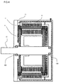
- FIG. 4 shows a sectional view of the rotating electric machine 3.
- the rotating electric machine 3 is covered with a case 11. If the rotating electric machine 3 is disposed between the engine 1 and the transmission 2, the case 11 is made up of the case of the engine and the case of the transmission. If the rotating electric machine 3 is mounted in the transmission 2, the case 11 is made up of the case of the transmission.
- the rotating electric machine 3 includes a rotor 4, a stator 5, and a housing 6.
- the rotor 4 is disposed inwardly in the stator 5 through a gap.
- the rotor 4 is fixed to a shaft 41, and both ends of the shaft 41 are rotatably supported by bearings 42A and 42B.
- the outer circumference of the stator 5 is fixed to the inner circumference of the housing 6.
- the outer circumference of the housing 6 is fixed inwardly in the case 11.
- the rotating electric machine 3 acts as a power generator and outputs power of three-phase alternating current.
- the current output from the stator 5 (for instance, 100A) is less than the current used by the rotating electric machine 3 acting as an electric machine.
- the rotating electric machine 3 presented in the example is a flat rotating electric machine with thickness in the direction of the rotation axis being less than the outside diameter.
- FIG. 5 shows an external view of the rotor 4 of the rotating electric machine 3.
- the rotor 4 includes a rotor core 42 and a permanent magnet 43, which is inserted into a hole formed in the rotor core 42.
- the permanent magnet 43 may assume not one magnet per one pole but the one divided into a plurality of pieces.
- the rotor 4 includes a plurality of magnetic poles disposed so that their polarities alternate in the direction of rotation.
- FIG. 6 shows an external view of the stator 5 of the rotating electric machine 3.
- the stator 5 includes a stator core 51 in which a plurality of slots are formed and a stator coil which is constituted with a plurality of conductors 52 stored in each of the plurality of slots.
- the rotor 4 includes the plurality of magnetic poles disposed so that their polarities alternate in the direction of rotation and is provided inside the stator 5 through a gap.
- the stator 5 of the rotating electric machine is constituted by electrically connecting a plurality of the conductors 52 disposed in the slots and disposed astride a plurality of the slots corresponding to the plurality of magnetic poles.
- the stator 5 includes a U phase lead section 53, a V phase lead section 54, and a W phase lead section 55 to connect a neutral point A56 and a neutral point B57, which are provided in the upper part of the coil end section constituted with the plurality of conductors 52, with an external device.
- FIG. 7 shows a connection circuit diagram of the stator 5 of the rotating electric machine 3.
- the stator 5 shown in FIG. 4 includes the U phase lead section 53, the V phase lead section 54, and the W phase lead section 55, which are to be connected with the outside in three-phase connection of 2Y distributed winding, and the neutral point A56 and the neutral point B57.
- FIG. 1 shows an enlarged view of a lead section of the stator 5 of the rotating electric machine 3.
- external-connection-side lead sections are aggregated into one position or location, for instance within a circumferential width of equal to or less than a predetermined number of slots of the stator core, so as to connect with cables.
- the external-connection-side lead sections can be aggregated into nine slots in total, although the number of the slots is not limited to nine.
- a U1 phase lead 531 which is extended from the innermost slot of the stator core 51
- a U2 phase lead 532 which is extended from the outermost slot of the stator core 51
- End sections of the U1 phase lead 531 and the U2 phase lead 532 are rounded by detaching coating and the lower surface of the U1 phase lead 531 and the upper surface of the U2 phase lead 532 are closely adhered so as to form a terminal.
- a V1 phase lead 541 and a V2 phase lead 542 are aligned in a position perpendicular to the axial direction on the circumference of the stator core 51. End sections of the V1 phase lead 541 and the V2 phase lead 542 are rounded by detaching coating and the lower surface of the V1 phase lead 541 and the upper surface of the V2 phase lead 542 are closely adhered so as to form a terminal.
- a W1 phase lead 551 and a W2 phase lead 552 are aligned in a position perpendicular to the axial direction on the circumference of the stator core 51.
- End sections of the W1 phase lead 551 and the W2 phase lead 552 are rounded by detaching coating and the lower surface of the W1 phase lead 551 and the upper surface of the W2 phase lead 552 are closely adhered so as to form a terminal.
- the U phase lead section 53 of the external-connection-side lead section the U1 phase lead 531 and the U2 phase lead 532 are aligned as a pair
- the V phase lead section 54 the V1 phase lead 541 and the V2 phase lead 542 are aligned as a pair
- the W phase lead section 55 the W1 phase lead 551 and the W2 phase lead 552 are aligned as a pair, in parallel in a position perpendicular to the axial direction on the circumference of the stator core 51.
- the neutral point A56 shown in FIG. 6 is disposed outside, or at the right side in FIG. 6 of, the W1 phase lead 551 and the W2 phase lead 552 by leading the U1 phase neutral wire 561, the V1 phase neutral wire 562, and the W1 phase neutral wire 563 in the upper part of the coil end section of the plurality of conductors 52.
- the neutral point B57 shown in FIG. 6 is disposed outside, or at the left side in FIG.
- the U1 phase lead 531 and the U2 phase lead 532 by leading the U2 phase neutral wire 571, the V2 phase neutral wire 572, and the W2 phase neutral wire 573 in the upper part of the coil end section of the plurality of conductors 52.
- FIG. 2 shows a side view of the lead section of the stator 5 of the rotating electric machine 3.
- the lead sections 53, 54, and 55 for external connection which are aligned in parallel in a position perpendicular to the axial direction on the circumference of the stator core 51, are aggregated into one position or location so as to connect with cables.
- the neutral point A56 and the neutral point B57 are disposed in the both sides circumferentially out of the range of the lead sections 53, 54, and 55 for external connection over the coil end section of the plurality of conductors 52 so as to reduce the portion raised by routing or arranging neutral wires.
- the plurality of conductors 52 are formed into the final shape in advance so as to ensure insulation between the conductors and are bent at an obtuse angle so as not to apply much pressure on insulation coating.
- FIG. 8 shows an external view of a U1 phase assembly of the stator 5.
- a winding circuit is constituted with 12 magnetic poles, 72 slots, three phases of the stator coil, two slots per phase per pole that is determined by the number of poles, and four conductors per one pole of the magnetic poles, as shown in FIG. 18 .
- 12 slots are disposed per two magnetic poles (a pair of magnetic poles of N-pole and S-pole, with different polarities) of the rotor 4.
- four conductors are disposed in one slot so that four conductors are arranged per one pole of the magnetic poles in a plurality of slots formed side by side.
- FIG. 19 shows an arrangement in a slot.
- four conductors are radially disposed in a line per one slot, and divided into a set of a first conductor 81 and a second conductor 82, and a set of a third conductor 83 and a fourth conductor 84 from the outer circumference side.
- the winding circuit is constituted by an inner circuit including the third conductor 83 and the fourth conductor 84 of a plurality of conductors arranged in each of a plurality of slots and an outer circuit including the first conductor 81 and the second conductor 82 of a plurality of conductors arranged in each of a plurality of slots.
- the winding circuit is constituted with the four conductors, which are combinations of the two conductors of the inner circuit and the two conductors of the outer circuit. Namely, four layers of conductors are inserted per one slot.
- the U1 phase has the U1 phase lead 531 as a winding start.
- the inner circuit is constituted with the third and fourth conductors of the plurality of slots using a conductor 581 striding six slots.
- the conductor 581 interferes with the U1 phase lead 531 at the end of the circuit. Therefore, a conductor with a different slot stride width, i.e., a conductor 582 striding five slots, is used to shift the inner circuit to the adjacent slot on the same layer and then is wound twice so as to move the inner circuit through the second and third conductors of the plurality of slots, i.e., a conductor 583 striding six slots, to the outer circuit.
- the outer circuit is constituted with the first and second conductors of the plurality of slots, i.e., a conductor of a conductor 584 striding six slots.
- a conductor with a different slot stride width i.e., a conductor 585 striding five slots, is used to move the outer circuit to the adjacent slot on the same layer and is wound twice so as to constitute a circuit having the end of winding at the U1 phase neutral wire 561.
- FIG. 18 shows a plan table of each phase.
- the U1 phase has the slots No. 3 and 4 into which the two conductors of the inner circuit are inserted and the slots No. 4 and 5 into which the two conductors of the outer circuit are inserted.
- the conductors of the inner circuit and the outer circuit lie at positions different by one slot, and they become an apparently fractional-pitched winding (winding groove pitch is less than magnetic pole pitch).
- FIG. 9 shows an external view of a U2 phase assembly of the stator.
- the U2 phase has the U2 phase lead 532 as a winding start.
- the outer circuit is constituted with the first and second conductors of the plurality of slots using the conductor 584 striding six slots.
- the conductor 584 interferes with the U2 phase lead 532 at the end of the circuit. Therefore, a conductor with a different slot stride width, i.e., the conductor 585 striding five slots, is used to shift the outer circuit to the adjacent slot on the same layer and then is wound twice so as to move the outer circuit through the second and third conductors of the plurality of slots, i.e., the conductor 583 striding six slots, to the inner circuit.
- the inner circuit is constituted with the third and fourth conductors of the plurality of slots, i.e., the conductor of a conductor 581 striding six slots.
- a conductor with a different slot stride width i.e., the conductor 582 striding five slots, is used to move the inner circuit to the adjacent slot on the same layer and is wound twice so as to constitute a circuit having the end of winding at the U2 phase neutral wire 571.
- FIG. 18 shows a plan table of each phase.
- the U2 phase has the slots No. 3 and 4 into which the two conductors of the inner circuit are inserted and the slots No. 4 and 5 into which the two conductors of the outer circuit are inserted.
- the conductors of the inner circuit and the outer circuit lie at positions different by one slot, and they become an apparently fractional-pitched winding.
- FIG. 10 shows an external view of a U phase assembly of the stator, which is an assembly of the U1 phase shown in FIG. 8 and the U2 phase shown in FIG. 9 .
- the U1 phase lead 531 and the U2 phase lead 532 are aligned in a position perpendicular to the axial direction, and the U1 phase neutral wire 561 and the U2 phase neutral wire 571 are disposed in the circumferentially outwardly opposite direction.
- the V phase and W phase assemblies each have the phase lead as a winding start
- a conductor with a different slot stride width is used to shift the inner circuit constituted with the third and fourth conductors of the plurality of slots to the adjacent slot and is wound twice so as to move the inner circuit through the second and third conductors of the plurality of slots to the outer circuit constituted with the first and second conductors of the plurality of slots
- a conductor with a different slot stride width is used to move the outer circuit to the adjacent slot and is wound twice so as to constitute a circuit having the end of winding at the phase neutral wire.
- FIG. 18 shows a plan table of each phase.
- the U phase has the slots No. 3 and 4 into which the four conductors of the inner circuit are inserted and the slots No. 4 and 5 into which the four conductors of the outer circuit are inserted.
- the conductors of the inner circuit and the outer circuit lie at positions different by one slot, and they become an apparently fractional-pitched winding.
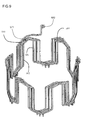
- FIG. 11 illustrates the formed or molded shape of the neutral wire A.
- the neutral wire A is constituted with the U1 phase neutral wire 561, which is the end of winding of the U1 phase, the V1 phase neutral wire 562, which is the end of winding of the V1 phase, and the W1 phase neutral wire 563, which is the end of winding of the W1 phase.
- Each of the neutral wires 561, 562, and 563 is supposed to be a conductor having been formed or molded into the final shape in advance so as to ensure insulation between the conductors and bent at an obtuse angle so as not to apply much pressure on insulation coating.
- three types of forming molds are required so as to form three types of neutral wires with different lengths into the final shape in advance.
- the forming mold of the U1 phase neutral wire 561, which is the end of winding of the U1 phase, is divided into regions I, II, and III.
- the shapes of a corresponding part of the neutral wire 561, a corresponding part of the neutral wire 562, and the neutral wire 563 are the same.
- the shapes of a corresponding part of the neutral wire 561 and a corresponding part of the neutral wire 562 are the same.
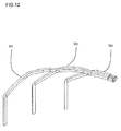
- FIG. 12 shows an external view of a pair of three neutral wires A.
- the ends of the U1 phase neutral wire 561, the V1 phase neutral wire 562, and the W1 phase neutral wire 563 that have been formed into the final shape in advance are TIG-welded into a state of a subassembly of a neutral wire, which is a set of three neutral wires.
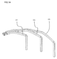
- FIG. 13 illustrates the formed or molded shape of the neutral wire B.
- the neutral wire B is constituted with the U2 phase neutral wire 571, which is the end of winding of the U2 phase, the V2 phase neutral wire 572, which is the end of winding of the V2 phase, and the W2 phase neutral wire 573, which is the end of winding of the W2 phase.
- Each of the neutral wires 571, 572, and 573 is supposed to be a conductor having been formed or molded into the final shape in advance so as to ensure insulation between the conductors and bent at an obtuse angle so as not to apply much pressure on insulation coating.
- three types of forming molds are required so as to form three types of neutral wires with different lengths into the final shape in advance.
- the forming mold of the W2 phase neutral wire 573 which is the end of winding of the W2 phase, is divided into regions I, II, and III.
- the shapes of a corresponding part of the neutral wire 573, a corresponding part of the neutral wire 572, and the neutral wire 571 are the same.
- the shapes of a corresponding part of the neutral wire 573 and a corresponding part of the neutral wire 572 are the same.
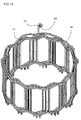
- FIG. 14 shows an external view of a pair of three neutral wires B.
- the ends of the U2 phase neutral wire 571, the V2 phase neutral wire 572, and the W2 phase neutral wire 573 that have been formed into the final shape in advance are TIG-welded into a state of a subassembly of a neutral wire, which is a set of three neutral wires.
- isolation between the conductors is ensured and high manufacturing workability is achieved by reducing the number of types of the conductors inserted into the stator core.
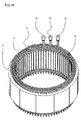
- FIG. 15 shows an external view of neutral wires and lead wires of the stator 5.
- the U phase lead section 53, the V phase lead section 54, and the W phase lead section 55 which are the leads to be connected with the outside, are aligned in parallel in a position perpendicular to the axial direction, and the neutral point A56 and the neutral point B57 are disposed in the opposite direction circumferentially out of a range of the lead sections 53, 54, and 55.
- the region raised by leading the neutral point A56 and the neutral point B57 in the upper part of the coil end section is reduced so as to ensure a gap with the transmission section, and, even with the lead sections being concentrated into one position, a simple structure is achieved to ensure isolation between the conductors and high manufacturing workability.
- FIG. 16 shows an external view of the stator of the rotating electric machine according to the second embodiment of the present invention.
- the stator 5 includes the stator core 51 in which a plurality of slots are formed and a stator coil which is constituted with a plurality of conductors 52 stored in each of the plurality of slots.
- the stator 4 which includes a plurality of magnetic poles disposed so that their polarities alternate in the direction of rotation, is provided with respect to the stator 5 through a gap.
- the stator 5 of the rotating electric machine 3 is constituted by electrically connecting the plurality of the conductors 52 that are disposed in the plurality of the slots formed side by side and range astride a plurality of the slots corresponding to the plurality of magnetic poles.
- the stator 5 includes the U phase lead section 53, the V phase lead section 54, and the W phase lead section 55 to connect the neutral point A56 and the neutral point B57, which are provided in the upper part of the coil end section constituted with the plurality of conductors 52, with the outside.
- FIG. 17 shows an enlarged view of the lead section of the stator 5 of the rotating electric machine 3 that constitutes an embodiment of the present invention.
- Mainly, external-connection-side lead sections of a stator of an electric vehicle motor are aggregated into one position or location so as to connect with cables.
- the U1 phase lead 531 which is extended from the innermost slot of the stator core 51
- the U2 phase lead 532 which is extended from the outermost slot of the stator core 51
- a side surface of the U1 phase lead 531 and that of the U2 phase lead 532 are closely adhered so as to connect with a terminal 7.
- the V1 phase lead 541 and the V2 phase lead 542 are aligned in a position perpendicular to the axial direction on the circumference of the stator core 51.
- a side surface of the V1 phase lead 541 and that of the V2 phase lead 542 are closely adhered so as to connect with the terminal 7.
- the W1 phase lead 551 and the W2 phase lead 552 are aligned in a position perpendicular to the axial direction on the circumference of the stator core 51.
- a side surface of the W1 phase lead 551 and that of the W2 phase lead 552 are closely adhered so as to connect with the terminal 7.
- the U1 phase lead 531 and the U2 phase lead 532 are aligned as a pair
- the V phase lead section 54 the V1 phase lead 541 and the V2 phase lead 542 are aligned as a pair
- the W phase lead section 55 the W1 phase lead 551 and the W2 phase lead 552 are aligned as a pair, in parallel in a position perpendicular to the axial direction on the circumference of the stator core 51.
- a gap with the transmission section is ensured by reducing the region raised by leading the neutral point A56 and the neutral point B57 in the upper part of the coil end section. In order to do so, the neutral point A56 is disposed outside or the right side in FIG.
- the neutral point B57 is disposed outside or the left side in FIG. 17 of the U2 phase lead 532 by routing the U2 phase neutral wire 571, the V2 phase neutral wire 572, and the W2 phase neutral wire 573 in the upper part of the coil end section of the plurality of conductors 52.
- a rotating electric machine and a manufacturing method thereof with high insulation and productivity can be achieved.
Landscapes
- Engineering & Computer Science (AREA)
- Power Engineering (AREA)
- Transportation (AREA)
- Mechanical Engineering (AREA)
- Windings For Motors And Generators (AREA)
- Manufacture Of Motors, Generators (AREA)
Applications Claiming Priority (1)
| Application Number | Priority Date | Filing Date | Title |
|---|---|---|---|
| JP2009154527A JP5070248B2 (ja) | 2009-06-30 | 2009-06-30 | 回転電機とその製造方法 |
Publications (2)
| Publication Number | Publication Date |
|---|---|
| EP2273654A2 true EP2273654A2 (de) | 2011-01-12 |
| EP2273654A3 EP2273654A3 (de) | 2017-01-25 |
Family
ID=42697291
Family Applications (1)
| Application Number | Title | Priority Date | Filing Date |
|---|---|---|---|
| EP10167755.7A Pending EP2273654A3 (de) | 2009-06-30 | 2010-06-29 | Elektrische Drehmaschine und Herstellungsverfahren dafür |
Country Status (3)
| Country | Link |
|---|---|
| US (1) | US8760019B2 (de) |
| EP (1) | EP2273654A3 (de) |
| JP (1) | JP5070248B2 (de) |
Cited By (6)
| Publication number | Priority date | Publication date | Assignee | Title |
|---|---|---|---|---|
| CN104756370A (zh) * | 2012-10-26 | 2015-07-01 | 日立汽车系统株式会社 | 旋转电机的定子 |
| CN105706339A (zh) * | 2013-11-12 | 2016-06-22 | 日立汽车系统株式会社 | 定子及具备该定子的旋转电机 |
| CN106605355A (zh) * | 2014-09-29 | 2017-04-26 | 日立汽车系统株式会社 | 旋转电机的定子以及具备该旋转电机的定子的旋转电机 |
| CN110073576A (zh) * | 2016-12-15 | 2019-07-30 | 三菱电机株式会社 | 电动机 |
| ES2899750A1 (es) * | 2020-09-14 | 2022-03-14 | Seg Automotive Germany Gmbh | Estator para una maquina electrica |
| DE112012003962B4 (de) | 2011-09-22 | 2022-03-31 | Hitachi Astemo, Ltd. | Rotierende elektrische Maschine und Verfahren zur Herstellung der rotierenden elektrischen Maschine |
Families Citing this family (21)
| Publication number | Priority date | Publication date | Assignee | Title |
|---|---|---|---|---|
| JP4893817B2 (ja) * | 2009-12-23 | 2012-03-07 | 株式会社デンソー | 燃料供給装置 |
| DE112011100077T5 (de) * | 2010-02-18 | 2012-10-31 | Aisin Aw Co., Ltd. | Anker für eine drehende elektrische Maschine |
| US8362666B2 (en) * | 2010-08-05 | 2013-01-29 | Remy Technologies, L.L.C. | Phase lead connection for parallel path electric machine |
| US20130033145A1 (en) * | 2011-08-02 | 2013-02-07 | Remy Technologies, Llc | Electric machine module insulation system and method |
| WO2013081225A1 (ko) * | 2011-12-02 | 2013-06-06 | 엘지전자 주식회사 | 전기기계의 고정자 및 이를 구비한 전동기, 전동기를 구비한 전기차량 |
| JP6001356B2 (ja) * | 2012-06-29 | 2016-10-05 | 株式会社ヴァレオジャパン | 電動圧縮機 |
| JP5954200B2 (ja) * | 2013-01-28 | 2016-07-20 | 株式会社デンソー | 回転電機の固定子 |
| US10110078B2 (en) * | 2013-08-23 | 2018-10-23 | Borgwarner Inc. | Distributed cascaded winding for electric machines |
| JP2015073386A (ja) * | 2013-10-03 | 2015-04-16 | トヨタ自動車株式会社 | 回転電機のステータ |
| JP2015109734A (ja) * | 2013-12-04 | 2015-06-11 | トヨタ自動車株式会社 | 回転電機のステータ |
| JP6457198B2 (ja) * | 2014-04-28 | 2019-01-23 | マブチモーター株式会社 | ブラシレスモータ |
| JP6046090B2 (ja) * | 2014-09-18 | 2016-12-14 | ファナック株式会社 | 通電カシメされた端子を有する電動機 |
| CN105472650B (zh) * | 2014-09-26 | 2020-05-01 | 诺基亚技术有限公司 | 用于对组播-广播单频网络测量记录日志的方法和装置 |
| JP6009519B2 (ja) * | 2014-10-16 | 2016-10-19 | 日立オートモティブシステムズ株式会社 | 回転電機および回転電機の製造方法 |
| US20160172931A1 (en) * | 2014-12-11 | 2016-06-16 | Joseph Michael Teets | Alternator rotor to stator integrated hrdrodynamic bearing |
| KR102342561B1 (ko) * | 2017-04-19 | 2021-12-23 | 엘지마그나 이파워트레인 주식회사 | 회전전기기기의 스테이터 |
| JP2020072576A (ja) * | 2018-10-31 | 2020-05-07 | 株式会社小松製作所 | 回転電機ステータ |
| US10998788B2 (en) | 2019-01-25 | 2021-05-04 | Borgwarner, Inc. | Electric machine with distributed winding having double cross end loops |
| US11025117B2 (en) * | 2019-01-28 | 2021-06-01 | Borgwarner Inc. | Distributed stator winding having parallel paths with crossing end loops |
| US12021423B2 (en) * | 2019-05-30 | 2024-06-25 | Hitachi Astemo Electric Motor Systems, Ltd. | Dynamo-electrical machine |
| CN113726040A (zh) * | 2021-08-11 | 2021-11-30 | 华为数字能源技术有限公司 | 电机定子、电机以及车辆 |
Citations (1)
| Publication number | Priority date | Publication date | Assignee | Title |
|---|---|---|---|---|
| JP2002218689A (ja) | 2001-01-18 | 2002-08-02 | Denso Corp | 相並列u字導体順次接続y形巻線の引き出し線構造 |
Family Cites Families (10)
| Publication number | Priority date | Publication date | Assignee | Title |
|---|---|---|---|---|
| US5508571A (en) * | 1994-12-12 | 1996-04-16 | General Motors Corporation | Neutral connection for wire wound stator |
| JP3342987B2 (ja) * | 1995-06-28 | 2002-11-11 | 三菱電機株式会社 | 車両用交流発電機 |
| JP3679632B2 (ja) * | 1998-07-29 | 2005-08-03 | 金 敬 洙 | 無負荷発電機 |
| JP4450125B2 (ja) * | 1999-12-09 | 2010-04-14 | 株式会社デンソー | 車両用回転電機 |
| JP2002084723A (ja) * | 2000-09-01 | 2002-03-22 | Mitsubishi Electric Corp | 車両用交流発電機 |
| FR2819117B1 (fr) * | 2000-12-21 | 2004-10-29 | Valeo Equip Electr Moteur | Alternateur a elements conducteurs en epingle pour vehicule automobile |
| JP4046270B2 (ja) * | 2002-05-24 | 2008-02-13 | 三菱電機株式会社 | 回転電機の固定子 |
| FR2840464B1 (fr) * | 2002-05-28 | 2004-09-03 | Valeo Equip Electr Moteur | Alternateur muni d'un stator a entrees vrillees |
| JP4546112B2 (ja) * | 2004-03-02 | 2010-09-15 | 日立オートモティブシステムズ株式会社 | 回転電機 |
| US20090140596A1 (en) * | 2007-11-30 | 2009-06-04 | Gm Global Technology Operations, Inc. | Methods and apparatus for a bar-wound stator with parallel connections |
-
2009
- 2009-06-30 JP JP2009154527A patent/JP5070248B2/ja active Active
-
2010
- 2010-06-29 EP EP10167755.7A patent/EP2273654A3/de active Pending
- 2010-06-29 US US12/826,408 patent/US8760019B2/en active Active
Patent Citations (1)
| Publication number | Priority date | Publication date | Assignee | Title |
|---|---|---|---|---|
| JP2002218689A (ja) | 2001-01-18 | 2002-08-02 | Denso Corp | 相並列u字導体順次接続y形巻線の引き出し線構造 |
Cited By (15)
| Publication number | Priority date | Publication date | Assignee | Title |
|---|---|---|---|---|
| DE112012003962B4 (de) | 2011-09-22 | 2022-03-31 | Hitachi Astemo, Ltd. | Rotierende elektrische Maschine und Verfahren zur Herstellung der rotierenden elektrischen Maschine |
| US9929612B2 (en) | 2012-10-26 | 2018-03-27 | Hitachi Automotive Systems, Ltd. | Stator for rotating electric machine |
| EP2913907A4 (de) * | 2012-10-26 | 2016-07-06 | Hitachi Automotive Systems Ltd | Stator für rotierende elektrische maschinen |
| CN104756370A (zh) * | 2012-10-26 | 2015-07-01 | 日立汽车系统株式会社 | 旋转电机的定子 |
| CN104756370B (zh) * | 2012-10-26 | 2017-05-17 | 日立汽车系统株式会社 | 旋转电机的定子 |
| US10916986B2 (en) | 2013-11-12 | 2021-02-09 | Hitachi Automotive Systems, Ltd. | Stator and rotating electric machine equipped with same |
| EP3070817A4 (de) * | 2013-11-12 | 2017-07-05 | Hitachi Automotive Systems, Ltd. | Stator und elektrische drehmaschine damit |
| CN105706339A (zh) * | 2013-11-12 | 2016-06-22 | 日立汽车系统株式会社 | 定子及具备该定子的旋转电机 |
| CN106605355B (zh) * | 2014-09-29 | 2019-03-08 | 日立汽车系统株式会社 | 旋转电机的定子以及具备该旋转电机的定子的旋转电机 |
| CN106605355A (zh) * | 2014-09-29 | 2017-04-26 | 日立汽车系统株式会社 | 旋转电机的定子以及具备该旋转电机的定子的旋转电机 |
| CN110073576A (zh) * | 2016-12-15 | 2019-07-30 | 三菱电机株式会社 | 电动机 |
| ES2899750A1 (es) * | 2020-09-14 | 2022-03-14 | Seg Automotive Germany Gmbh | Estator para una maquina electrica |
| CN114189081A (zh) * | 2020-09-14 | 2022-03-15 | Seg汽车德国有限公司 | 用于电的机器的定子 |
| US11621600B2 (en) | 2020-09-14 | 2023-04-04 | Seg Automotive Germany Gmbh | Stator for an electric machine |
| CN114189081B (zh) * | 2020-09-14 | 2024-03-08 | Seg汽车德国有限公司 | 用于电机的定子 |
Also Published As
| Publication number | Publication date |
|---|---|
| JP2011015459A (ja) | 2011-01-20 |
| JP5070248B2 (ja) | 2012-11-07 |
| EP2273654A3 (de) | 2017-01-25 |
| US20110001373A1 (en) | 2011-01-06 |
| US8760019B2 (en) | 2014-06-24 |
Similar Documents
| Publication | Publication Date | Title |
|---|---|---|
| US8760019B2 (en) | Rotating electric machine terminal arrangement | |
| US8497618B2 (en) | Stator for rotatry electrical machine including an insulating bobbin | |
| US8878407B2 (en) | Rotary electric machine and method for manufacturing a stator coil connecting unit therefor | |
| JP6072238B2 (ja) | 回転電機の製造方法 | |
| EP3176912B1 (de) | Stator und drehmaschine | |
| US8610328B2 (en) | Rotary electric machine | |
| US10910899B2 (en) | Rotary electric machine | |
| US10236738B2 (en) | Rotary electric machine | |
| US9641036B2 (en) | Rotary electric machine | |
| EP1876685B1 (de) | Motorstatorstruktur | |
| US9667114B2 (en) | Stator, manufacturing method therefor, and rotary electric machine that includes stator | |
| JP2008167604A (ja) | インナーロータ型モールドブラシレスモータのステータ | |
| CN108880018B (zh) | 一种无刷电机定子及无刷电机 | |
| US20190013710A1 (en) | Rotary Electric Machine | |
| US10348149B2 (en) | Stator for rotating electric machine and rotating electric machine including the stator | |
| CN112910116B (zh) | 旋转电机 | |
| CN107086692B (zh) | 电机及其定子绝缘组件 | |
| JP2014192997A (ja) | 電動モータ | |
| CN214101001U (zh) | 一种电机定子及电机 | |
| JP2011229290A (ja) | モータ | |
| WO2023140071A1 (ja) | モータステータ及びこれを備えるモータ | |
| JP6968215B2 (ja) | 回転電機 | |
| JP5144180B2 (ja) | ステータの中点連結構造 | |
| CN109891716B (zh) | 设置有具有改良配置的互连的旋转电机的定子 | |
| CN111478487A (zh) | 一种电机定子及电机 |
Legal Events
| Date | Code | Title | Description |
|---|---|---|---|
| PUAI | Public reference made under article 153(3) epc to a published international application that has entered the european phase |
Free format text: ORIGINAL CODE: 0009012 |
|
| 17P | Request for examination filed |
Effective date: 20100920 |
|
| AK | Designated contracting states |
Kind code of ref document: A2 Designated state(s): AL AT BE BG CH CY CZ DE DK EE ES FI FR GB GR HR HU IE IS IT LI LT LU LV MC MK MT NL NO PL PT RO SE SI SK SM TR |
|
| AX | Request for extension of the european patent |
Extension state: BA ME RS |
|
| PUAL | Search report despatched |
Free format text: ORIGINAL CODE: 0009013 |
|
| AK | Designated contracting states |
Kind code of ref document: A3 Designated state(s): AL AT BE BG CH CY CZ DE DK EE ES FI FR GB GR HR HU IE IS IT LI LT LU LV MC MK MT NL NO PL PT RO SE SI SK SM TR |
|
| AX | Request for extension of the european patent |
Extension state: BA ME RS |
|
| RIC1 | Information provided on ipc code assigned before grant |
Ipc: H02K 3/50 20060101AFI20161219BHEP Ipc: H02K 15/00 20060101ALI20161219BHEP Ipc: H02K 3/28 20060101ALI20161219BHEP |
|
| STAA | Information on the status of an ep patent application or granted ep patent |
Free format text: STATUS: EXAMINATION IS IN PROGRESS |
|
| 17Q | First examination report despatched |
Effective date: 20190524 |
|
| STAA | Information on the status of an ep patent application or granted ep patent |
Free format text: STATUS: EXAMINATION IS IN PROGRESS |
|
| STAA | Information on the status of an ep patent application or granted ep patent |
Free format text: STATUS: EXAMINATION IS IN PROGRESS |
|
| RAP3 | Party data changed (applicant data changed or rights of an application transferred) |
Owner name: HITACHI ASTEMO, LTD. |