EP2272700B1 - Ablegbare Dachanordnung für ein langes Fahrzeug wie z. B. einen Reisebus - Google Patents
Ablegbare Dachanordnung für ein langes Fahrzeug wie z. B. einen Reisebus Download PDFInfo
- Publication number
- EP2272700B1 EP2272700B1 EP09380128A EP09380128A EP2272700B1 EP 2272700 B1 EP2272700 B1 EP 2272700B1 EP 09380128 A EP09380128 A EP 09380128A EP 09380128 A EP09380128 A EP 09380128A EP 2272700 B1 EP2272700 B1 EP 2272700B1
- Authority
- EP
- European Patent Office
- Prior art keywords
- cover
- elements
- pivoting structure
- vehicle
- roof
- Prior art date
- Legal status (The legal status is an assumption and is not a legal conclusion. Google has not performed a legal analysis and makes no representation as to the accuracy of the status listed.)
- Not-in-force
Links
Images


Classifications
-
- B—PERFORMING OPERATIONS; TRANSPORTING
- B60—VEHICLES IN GENERAL
- B60J—WINDOWS, WINDSCREENS, NON-FIXED ROOFS, DOORS, OR SIMILAR DEVICES FOR VEHICLES; REMOVABLE EXTERNAL PROTECTIVE COVERINGS SPECIALLY ADAPTED FOR VEHICLES
- B60J7/00—Non-fixed roofs; Roofs with movable panels, e.g. rotary sunroofs
- B60J7/02—Non-fixed roofs; Roofs with movable panels, e.g. rotary sunroofs of sliding type, e.g. comprising guide shoes
- B60J7/04—Non-fixed roofs; Roofs with movable panels, e.g. rotary sunroofs of sliding type, e.g. comprising guide shoes with rigid plate-like element or elements, e.g. open roofs with harmonica-type folding rigid panels
- B60J7/047—Non-fixed roofs; Roofs with movable panels, e.g. rotary sunroofs of sliding type, e.g. comprising guide shoes with rigid plate-like element or elements, e.g. open roofs with harmonica-type folding rigid panels movable to overlapping or nested relationship
Definitions
- the present invention relates to a sliding roof device for a long vehicle, applicable for example to sightseeing buses or coaches, and to other long vehicles such as railway wagons, ships, etc. in which it is of interest to clear the roof surface to facilitate a better view of surroundings which are being visited.
- Patent EP-A-0827856 discloses a bus for sightseeing tours provided with a sliding roof formed by a flexible canopy fixed on bars arranged to move along guide rails to cover or uncover an opening in the roof of the vehicle.
- Patent EP-A-1332904 describes a telescopic cover for covering relatively large areas.
- the cover comprises a plurality of cover elements movable between an extracted position, in which they cover the area, and a retracted position, in which they occupy a reduced collecting area.
- the cover elements comprise a cover panel and at least one front sliding foot and one rear sliding foot on each side, said sliding feet being arranged to run along lateral guide elements.
- the cover elements are identical to one another and, in the extended position, at least one cover element rests on the guide element with rear sliding feet and is supported with a front edge on a rear edge of an adjacent cover element.
- a drawback of this telescopic cover is that it does not allow substantially uncovering the entire area that it is capable of covering due to the fact that when the plurality of cover elements are superimposed in the retracted position, they always occupy a significant portion of the area.
- Patent FR-A-2913373 discloses a sliding roof for a utility automobile.
- the sliding roof comprises several cover panels movable between an extended position, in which they cover an opening in the roof of the passenger compartment, and a retracted position on a support structure, which is associated with means for supporting and guiding the support structure together with the cover panels between the retracted position, an intermediate position located above a trunk compartment, and a considerably horizontal folded position at the upper part of said trunk compartment.
- Driving means are arranged to move the support structure together with the cover panels between the different positions.
- the supporting and guiding means comprise, on each side of the vehicle, a follower connected to the support structure cooperating with a longitudinal rail to guide the support structure together with the cover panels between the retracted and intermediate positions, a pivoting telescopic arm having a first end connected in an articulated manner to the rear part of the support structure and another end connected in an articulated manner to the structure of the vehicle, a follower connected to said pivoting telescopic arm cooperating with a rail with a shape adapted to continuously guide the support structure together with the cover panels between the retracted, intermediate and folded positions, and means for reducing the trajectory of said driving means.
- the sliding roof described in the mentioned patent FR-A-2913373 has several drawbacks.
- the supporting, guiding and driving means for moving the support structure together with the cover panels between the different positions form an extremely complex assembly which can be expensive to manufacture and maintain.
- the support structure together with the cover panels are supported in cantilever by the pivoting telescopic arm during its movements between the intermediate and folded positions, and this forces oversizing the supporting, guiding and driving means to withstand the forces to which they are subjected.
- the considerably horizontal position at a lower level than the roof of the vehicle reached by the support structure together with the cover panels in the folded position has little application in the field of long vehicles, such as sightseeing buses or coaches, since it imposes assembly storing conditions with a reduction of the useful space.
- the present invention contributes to mitigating the previous and other drawbacks by providing a sliding roof device for a long vehicle, applicable to a sightseeing coach or bus, of the type comprising a plurality of sliding cover elements arranged to move between an extended position, in which said cover elements are arranged one after another covering an opening in the roof of the long vehicle, and a retracted position which leaves a large part of said opening in the roof of the long vehicle uncovered, and in which the cover elements are mutually superimposed or fitted in a compact arrangement supported by a pivoting structure, which is installed at an end of the long vehicle such that it can pivot between an unfolded position, in which said pivoting structure together with the cover elements cover a portion of the opening in the roof of the long vehicle, and a folded position, in which the pivoting structure together with the cover elements are in a withdrawn position at said end of the long vehicle.
- the sliding roof device is characterized in that the pivoting structure has, close to a front end, followers arranged to run along substantially horizontal longitudinal folding guides and, close to a rear end, one or more articulations connected to respective driving arms installed such that it can pivot about a transverse horizontal shaft located at a lower level than said folding guides under the drive of an actuator.
- the pivoting structure has at all times, including the stage of its movements between the unfolded and folded positions, its front end supported on the folding guides and its rear end supported by the driving arms.
- This allows the mechanisms for supporting, guiding and driving the movements of the pivoting structure together with the cover elements between the unfolded and folded positions to be extremely simple and lightweight, and therefore have a low cost, the maintenance likewise being minimized.
- These mechanisms further allow the pivoting structure together with the cover elements to reach a substantially vertical position at a rear end of the long vehicle when they are in said folded position, which is very advantageous in the case of a sightseeing bus or coach since they leave substantially the entire opening in the roof thereof uncovered.
- the sliding roof device for a long vehicle of this invention is of the type described in patent FR-A-2913373 (although this document describes a utility vehicle) and thus comprises a plurality of sliding cover elements 2 (see Figures 1 and 4 ) arranged to move between an extended position, in which said cover elements 2 are arranged one after another covering an opening in the roof of the vehicle, and a retracted position which leaves a large part or all of said opening in the roof of the vehicle uncovered, the cover elements 2 then being mutually superimposed or fitted in a compact arrangement supported by a pivoting structure 3.
- This pivoting structure is usually installed at a rear end of the vehicle such that it can pivot between an unfolded position, in which said pivoting structure 3 together with the cover elements 2 cover a portion of the opening in the roof of the vehicle, and a folded position, in which the pivoting structure 3 together with the cover elements 2 are in a withdrawn position at said rear end of the vehicle, having to provide a storage area for that purpose.
- the device of the invention has been designed for its application to a long vehicle 50, such as a sightseeing bus which has been schematically shown in Figure 1 , comprising structural struts 51, a lower floor 53, an upper floor 54 delimited by side walls 52, which can be occupied by the users in order to considerably improve the conditions for viewing the surroundings from said raised position, it being important in said case to maximally clear any obstacle, such as a roof of the vehicle if the weather conditions allow it.
- a long vehicle 50 such as a sightseeing bus which has been schematically shown in Figure 1 , comprising structural struts 51, a lower floor 53, an upper floor 54 delimited by side walls 52, which can be occupied by the users in order to considerably improve the conditions for viewing the surroundings from said raised position, it being important in said case to maximally clear any obstacle, such as a roof of the vehicle if the weather conditions allow it.
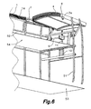
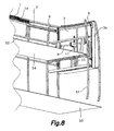
- a pivoting structure 3 is provided, located at the rear part of the vehicle and provided close to a front end with followers 6 (for example, wheels) arranged to run along substantially horizontal longitudinal folding guides 7 (see Figures 5 and 6 ) and close to a rear end with articulations 20 connected to respective driving arms 8 installed such that they can pivot about a transverse horizontal shaft 9 located at a lower level than said folding guides 7 under the drive of an actuator.
- followers 6 for example, wheels
- the actuator comprises a hydraulic cylinder 10 the rod 11 of which is connected to a rack 12 meshed with a gear wheel 13 fixed to said shaft 9 or to said driving arm 8 as can be seen in the enlarged detail of Figure 4 .
- This special organization of the guide means and of the drive or thrust mechanism of the structure provides a safe and effective drive of the assembly, bearing in superposition the series of cover elements 2 (see Figures 5 to 7 ) duly supported at all times. Furthermore, the pivoting structure 3 together with the plurality of cover elements 2 supported by it adopt a substantially vertical position at a rear end of the long vehicle 50 when they are in said folded position, such that the vertical position next to the back 60 of the long vehicle 50 completely clears the roof of the vehicle and minimizes the useful space to be reserved for storing the pivoting structure 3, in its concealed state.
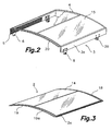
- the cover elements 2 are arranged to move (for example, by traction means such as a chain or flexible element and a linear actuator, according to the state of the art) along a plurality of first guide elements 1 between said extended and retracted positions, and the pivoting structure 3 is provided with an upper cover element 4 and second guide elements 5 (see Figure 2 ) defined in the inner face of side flaps 3a, such that, when said pivoting structure 3 is in said unfolded position ( Figure 5 ), said upper cover element 4 covers a portion of the opening in the roof of the long vehicle 50 and said second guide elements 5 are correspondingly aligned with said plurality of first guide elements 1 and arranged to receive the cover elements 2 under said upper cover element 4 of the pivoting structure 3.
- traction means such as a chain or flexible element and a linear actuator, according to the state of the art
- the first guide elements 1 include sloping sections 1a to successively guide each of the cover elements 2 under the adjacent cover element 2 when the cover elements 2 are moved from the extended position to the retracted position, until the plurality of cover elements 2 are arranged one under another and under the upper cover element 4 in the pivoting structure 3 ( Figure 5 ), forming a compact package.
- Figure 3 shows one of the cover elements 2 (all of them are initially identical, although they could have a different length) which includes one or more curved cover panels 14, with a central part that is more raised than longitudinal side edges in which there are included small wheels 2a or a follower element to move over the mentioned guides 1, 1a in the sides.
- the upper cover element 4 of the pivoting structure 3 in turn comprises, as shown in Figure 2 , one or more curved cover panels 15, with a central part that is more raised than longitudinal side edges in which it is finished by the mentioned flaps 3a.
- first and second cover panels 14, 15 are transparent.
- each of the first cover elements 2 has at one end a wide transverse channel 18 for collecting and draining water and at the other opposite end a small roof 19, with a narrow transverse channel 19a, for drainage (to facilitate the insertion in the mentioned guides 1, 1a without jams), arranged to cover a joint between the first cover element 2 and another adjacent first cover element 2.
- water draining channels 17 to collect the water falling on the first and second cover elements 2, 4 when they are in the extended position and draining it out of the long vehicle 50 through a suitable conduit, not shown.
- Said water draining channels 17 form a base for supporting the assembly of mentioned guide elements 1,5.
- the pivoting structure 3 comprises, under the upper cover element 4, side skirts or flaps 3a supporting the second guide elements 5 and between which (in the inner face thereof provided with a plurality of opposite grooves) there is housed the plurality of cover elements 2 one under another in the retracted position.
- the pivoting structure 3 has at one end a small roof 20 arranged to cover a joint between the pivoting structure 3 and an adjacent first cover element 2.
Landscapes
- Engineering & Computer Science (AREA)
- Mechanical Engineering (AREA)
- Body Structure For Vehicles (AREA)
Claims (12)
- Schiebedacheinrichtung für ein langes Fahrzeug, anwendbar auf einen Städtebesichtigungsbus, von der Art, die eine Mehrzahl von Deckelementen (2) aufweist, welche derart angeordnet sind, dass sie zwischen einer ausgefalteten Lage, in der die besagten Schiebedachelemente (2) nacheinander angeordnet sind, um eine Öffnung im Dach des Fahrzeuges zu bedecken, und einer zusammengefalteten Lage, die einen grossen Teil besagter Öffnung im Dach des Fahrzeugs unbedeckt lässt, wobei die Deckelemente (2) gegenseitig überlagert sind oder eingepasst sind in eine kompakte, von einer schwenkbaren Struktur (3) getragenen Einrichtung, die an einem Ende des langen Fahrzeugs (50) derart zu installieren ist, dass sie schwenkbar ist zwischen einer auseinandergefalteten Lage, in der die schwenkbare Struktur (3) zusammen mit den Deckelementen (2) einen Teil der Öffnung im Dach des Fahrzeugs abdeckt, und einer zusammengefalteten Lage, in der sich die schwenkbare Struktur (3) zusammen mit den Deckelementen (2) am besagten Ende des Fahrzeugs befindet, dadurch gekennzeichnet, dass die schwenkbare Struktur (3) in der Nähe ihres vorderen Endes Kurvenrollen (6) aufweist, die derart ausgestaltet sind, dass sie entlang von im wesentlichen horizontalen Längsführungen (7) verlaufen, und dass sie in der Nähe ihres hinteren Endes zumindest ein Gelenk (20) aufweist, das mit einem Antriebsarm (8) verbunden ist, der derart ausgestaltet ist, dass er um einen horizontalen Querschaft (9) schwenkbar ist, der sich auf einem niedrigeren Niveau befindet als die genannten Faltführungen (7) unter dem Antrieb eines Reglers.
- Einrichtung gemäss Anspruch 1, dadurch gekennzeichnet, dass die schwenkbare Struktur (3), zusammen mit der Mehrzahl der von ihr getragenen Deckelemente (2), wenn sie sich in der besagten zusammengefalteten Lage befinden, an einem hinteren Ende des langen Fahrzeugs (50) eine wesentlich vertikale Stellung einnehmen.
- Einrichtung gemäss Anspruch 2, dadurch gekennzeichnet, dass die Deckelemente (2) derart ausgestaltet sind, dass sich sie entlang einer Mehrzahl erster Führungselemente (1) zwischen der genannten ausgefahrenen und der zusammengefalteten Lage bewegen, und dass die schwenkbare Struktur (3) mit einem oberen Deckelement (4) und mit zweiten Führungselementen (5) ausgestattet ist, so dass dieses obere Deckelement (4), wenn sich die schwenkbare Struktur (3) in der genannten ausgefalteten Lage befindet, einen Teil der Öffnung im Dach des langen Fahrzeuges (50) abdeckt, und dass die genannten zweiten Führungselemente (5) entsprechend mit der Mehrzahl der ersten Führungselemente (1) fluchten, und so ausgestaltet sind, dass sie die Deckelemente (2) unter dem genannten oberen Deckelement (4) der schwenkbaren Struktur (3) aufnehmen.
- Einrichtung gemäss Anspruch 3, dadurch gekennzeichnet, dass die genannten ersten Führungselemente (1) Schrägabschnitte (1a) aufweisen, um nacheinander jedes der Deckelemente (2) unter dem benachbarten Deckelement (2) zu führen, wenn die Deckelemente (2) von der ausgefahrenen Lage zur zusammengezogenen Lage gebracht werden, bis die Mehrzahl der Deckelemente (2) jeweils untereinander, und unter dem oberen Deckelement (4) der schwenkbaren Struktur (3) angeordnet sind.
- Einrichtung gemäss Anspruch 3, dadurch gekennzeichnet, dass jedes der Deckelemente (2) zumindest eine gekrümmte Deckplatte (14) mit einem zentralen Abschnitt aufweist, der stärker angehoben ist als die länglichen Seitenkanten, und dass das obere Deckelement (4) der schwenkbaren Struktur (3) zumindest eine zweite gekrümmte Deckplatte (15) mit einem zentralen Abschnitt aufweist, der stärker angehoben ist als die länglichen Seitenkanten.
- Einrichtung gemäss Anspruch 5, dadurch gekennzeichnet, dass die schwenkbare Struktur (3) unter dem oberen Deckelement (4), Seitenleisten (16) aufweist, die die zweiten Führungselemente (5) tragen, und zwischen welchen in der zusammengezogenen Lage die Mehrzahl der Deckelemente (2) untereinander angebracht ist.
- Einrichtung gemäss Anspruch 6, dadurch gekennzeichnet, dass die ersten und zweiten Deckplatten (14, 15) transparent sind.
- Einrichtung gemäss Anspruch 1, dadurch gekennzeichnet, dass der genannte Regler einen hydraulischen Zylinder (10) aufweist, dessen Stange (11) mit einem Gestell (12) verbunden ist, das in Eingriff steht mit einem Getrieberad (13), das an genanntem Schaft (9) oder genanntem Antriebsarm (8) befestigt ist.
- Einrichtung gemäss Anspruch 3, dadurch gekennzeichnet, dass jedes der ersten Deckelemente (2) an einem ersten Ende einen Querkanal (18) zum Aufnehmen und Ableiten von Wasser aufweist, und am gegenüberliegenden Ende ein kleines Dach (19) zur Überdeckung eines Spaltes zwischen dem ersten Deckelement (2) und einem anderen benachbarten ersten Deckelement (2) aufweist.
- Einrichtung gemäss Anspruch 9, dadurch gekennzeichnet, dass in dem genannten kleinen Dach (19) eine Nute zum Aufsammeln und Abführen von Wasser vorgesehen ist.
- Einrichtung gemäss Anspruch 9 oder 10, dadurch gekennzeichnet, dass unter den ersten Führungselementen (1) und den Faltführungen (7) wasserableitende Kanale (17) vorgesehen sind, um das Wasser aufzunehmen, das auf die ersten und zweiten Deckelemente (2, 4) fällt, wenn sie sich in der ausgezogenen Position befinden, und es aus dem langen Fahrzeug (50) abzuleiten.
- Einrichtung gemäss Anspruch 3, dadurch gekennzeichnet, dass die schwenkbare Struktur (3) an einem Ende ein kleines Dach (20) zur Überdeckung eines Spaltes zwischen der schwenkbaren Struktur (3) und einem benachbarten ersten Deckelement (2) aufweist.
Priority Applications (4)
| Application Number | Priority Date | Filing Date | Title |
|---|---|---|---|
| AT09380128T ATE543673T1 (de) | 2009-07-06 | 2009-07-06 | Ablegbare dachanordnung für ein langes fahrzeug wie z. b. einen reisebus |
| EP09380128A EP2272700B1 (de) | 2009-07-06 | 2009-07-06 | Ablegbare Dachanordnung für ein langes Fahrzeug wie z. B. einen Reisebus |
| US13/382,015 US20120139299A1 (en) | 2009-07-06 | 2010-06-22 | Collapsible Roof Device for a Long Vehicle Such a Touristic Bus |
| PCT/IB2010/001503 WO2011004227A1 (en) | 2009-07-06 | 2010-06-22 | Collapsible roof device for a long vehicle such a touristic bus |
Applications Claiming Priority (1)
| Application Number | Priority Date | Filing Date | Title |
|---|---|---|---|
| EP09380128A EP2272700B1 (de) | 2009-07-06 | 2009-07-06 | Ablegbare Dachanordnung für ein langes Fahrzeug wie z. B. einen Reisebus |
Publications (2)
| Publication Number | Publication Date |
|---|---|
| EP2272700A1 EP2272700A1 (de) | 2011-01-12 |
| EP2272700B1 true EP2272700B1 (de) | 2012-02-01 |
Family
ID=41278238
Family Applications (1)
| Application Number | Title | Priority Date | Filing Date |
|---|---|---|---|
| EP09380128A Not-in-force EP2272700B1 (de) | 2009-07-06 | 2009-07-06 | Ablegbare Dachanordnung für ein langes Fahrzeug wie z. B. einen Reisebus |
Country Status (4)
| Country | Link |
|---|---|
| US (1) | US20120139299A1 (de) |
| EP (1) | EP2272700B1 (de) |
| AT (1) | ATE543673T1 (de) |
| WO (1) | WO2011004227A1 (de) |
Families Citing this family (4)
| Publication number | Priority date | Publication date | Assignee | Title |
|---|---|---|---|---|
| NL2008118C2 (nl) * | 2012-01-13 | 2013-07-16 | Verachtert | Cabrioletvoertuig voor personenvervoer. |
| WO2013105860A1 (en) * | 2012-01-13 | 2013-07-18 | VERACHTERT, Augustinus Maria | Cabriobus |
| CN106080146B (zh) * | 2016-07-06 | 2018-07-10 | 石家庄中博汽车有限公司 | 客车敞闭两用车顶结构、双层旅游观光车及车顶敞闭变形方法 |
| CN106114168B (zh) * | 2016-07-06 | 2018-07-10 | 石家庄中博汽车有限公司 | 双层旅游观光车及其敞篷变形方法 |
Family Cites Families (11)
| Publication number | Priority date | Publication date | Assignee | Title |
|---|---|---|---|---|
| GB276839A (en) * | 1926-09-18 | 1927-09-08 | George Page | Improvements in or relating to hoods for char-a-banc omnibus or any type of motor vehicle body |
| CH124896A (de) * | 1927-01-14 | 1928-03-16 | Ramseier Streun & Cie | Karosseriebedachung für Motorwagen. |
| GB301603A (en) * | 1927-10-17 | 1928-12-06 | George Harold Wenham | Improvements in or relating to folding hoods of vehicles |
| CA1056418A (en) * | 1976-12-30 | 1979-06-12 | Jean-Marc Parent | Camping vehicle body |
| EP0827856B1 (de) | 1996-08-30 | 2001-12-05 | Berliner Verkehrsbetriebe (BVG) Anstalt des öffentlichen Rechts | Omnibus für Stadtrundfahrten, insbesondere Ein- und Doppeldecker |
| ITMI20020192A1 (it) | 2002-02-04 | 2003-08-04 | Ignazio Sanna | Copertura telescopica a elementi embricati |
| DE20204110U1 (de) * | 2002-03-14 | 2002-09-12 | Inalfa Ind Bv | Fahrzeug mit einer Dachanordnung; und eine solche Dachanordnung |
| FR2857625B1 (fr) * | 2003-07-16 | 2008-07-18 | France Design | Vehicule a toit ouvrant escamotable et procede de rangement d'un tel toit, avec un systeme de basculement horizontal |
| DE10345275A1 (de) * | 2003-09-30 | 2005-04-21 | Karmann Gmbh W | Kraftfahrzeug |
| FR2913373B1 (fr) | 2007-03-07 | 2011-04-15 | Peugeot Citroen Automobiles Sa | Vehicule automobile decouvrable. |
| EP2105333B1 (de) * | 2008-03-26 | 2012-06-20 | Inalfa Roof Systems Group B.V. | Dachanordnung für ein Fahrzeug und Verfahren zum Betreiben davon |
-
2009
- 2009-07-06 AT AT09380128T patent/ATE543673T1/de active
- 2009-07-06 EP EP09380128A patent/EP2272700B1/de not_active Not-in-force
-
2010
- 2010-06-22 US US13/382,015 patent/US20120139299A1/en not_active Abandoned
- 2010-06-22 WO PCT/IB2010/001503 patent/WO2011004227A1/en active Application Filing
Also Published As
| Publication number | Publication date |
|---|---|
| WO2011004227A1 (en) | 2011-01-13 |
| ATE543673T1 (de) | 2012-02-15 |
| US20120139299A1 (en) | 2012-06-07 |
| EP2272700A1 (de) | 2011-01-12 |
Similar Documents
| Publication | Publication Date | Title |
|---|---|---|
| US6474731B2 (en) | Motor vehicle with an openable vehicle roof | |
| US5542735A (en) | Lengthwise movable vehicle roof | |
| DE10028405B4 (de) | Kofferraumdeckelanordnung für ein Fahrzeug mit einen einklappbaren Verdeck | |
| EP1473199B1 (de) | Trennvorrichtung für einen Fahrzeuginnenraum | |
| DE102005056715B4 (de) | Kraftfahrzeug und Dachverstaumechanismus | |
| JP5119325B2 (ja) | モジュール型スライド式剛性パネルルーフシステム | |
| US6669201B1 (en) | Folding roof system and vehicle equipped therewith | |
| JP3195256U (ja) | カブリオ・バス | |
| EP2272700B1 (de) | Ablegbare Dachanordnung für ein langes Fahrzeug wie z. B. einen Reisebus | |
| US6957843B2 (en) | Folding roof for vehicle with sliding elements | |
| DE10212575B4 (de) | Versenkbares Dach für Personenkraftfahrzeuge, insbesondere Hartdach für Cabriolets, Roadster oder dergleichen | |
| CN102126419B (zh) | 具有一种顶棚结构的敞篷车 | |
| US20070090664A1 (en) | Hardtop vehicle roof with external roof kinematic system | |
| US9586463B2 (en) | Top for an openable vehicle roof | |
| DE10234350B4 (de) | Abdeckvorrichtung für ein ablegbares Dach eines Cabriolets und Cabriolet mit einer derartigen Abdeckvorrichtung | |
| DE102011051891A1 (de) | Dachbox und verfahrbarer Dachgepäckträger für Kraftfahrzeuge | |
| EP0570601A1 (de) | Fahrzeugkarosserie mit abnehmbarem dach | |
| US20090045655A1 (en) | Multi-Panel Panoramic Roof Module | |
| US9630661B1 (en) | Retractable roof stored under an active spoiler | |
| US7416246B2 (en) | Motor vehicle with at least two movable parts | |
| US20080258509A1 (en) | Vehicle Roof With a Roof Part Mounted Movably on a Central Guide | |
| JP4828064B2 (ja) | 連結された同一車両の連続する二つの客車間の車両間通路用保護手段 | |
| EP1817191B1 (de) | Dachsystem mit öffnungsmechanismus für ein auto | |
| EP0530867B1 (de) | Motorfahrzeug mit einem zu öffnenden Dach und zu öffnendes Dach für den Gebrauch in einem Motorfahrzeug | |
| CN104245378A (zh) | 用于车辆的敞开式车顶构造 |
Legal Events
| Date | Code | Title | Description |
|---|---|---|---|
| PUAI | Public reference made under article 153(3) epc to a published international application that has entered the european phase |
Free format text: ORIGINAL CODE: 0009012 |
|
| AK | Designated contracting states |
Kind code of ref document: A1 Designated state(s): AT BE BG CH CY CZ DE DK EE ES FI FR GB GR HR HU IE IS IT LI LT LU LV MC MK MT NL NO PL PT RO SE SI SK SM TR |
|
| AX | Request for extension of the european patent |
Extension state: AL BA RS |
|
| 17P | Request for examination filed |
Effective date: 20110607 |
|
| GRAP | Despatch of communication of intention to grant a patent |
Free format text: ORIGINAL CODE: EPIDOSNIGR1 |
|
| RIC1 | Information provided on ipc code assigned before grant |
Ipc: B60J 7/06 20060101AFI20110630BHEP |
|
| GRAS | Grant fee paid |
Free format text: ORIGINAL CODE: EPIDOSNIGR3 |
|
| GRAA | (expected) grant |
Free format text: ORIGINAL CODE: 0009210 |
|
| AK | Designated contracting states |
Kind code of ref document: B1 Designated state(s): AT BE BG CH CY CZ DE DK EE ES FI FR GB GR HR HU IE IS IT LI LT LU LV MC MK MT NL NO PL PT RO SE SI SK SM TR |
|
| REG | Reference to a national code |
Ref country code: GB Ref legal event code: FG4D |
|
| REG | Reference to a national code |
Ref country code: AT Ref legal event code: REF Ref document number: 543673 Country of ref document: AT Kind code of ref document: T Effective date: 20120215 Ref country code: CH Ref legal event code: EP |
|
| REG | Reference to a national code |
Ref country code: DE Ref legal event code: R096 Ref document number: 602009005037 Country of ref document: DE Effective date: 20120329 |
|
| REG | Reference to a national code |
Ref country code: SE Ref legal event code: TRGR |
|
| REG | Reference to a national code |
Ref country code: NL Ref legal event code: VDEP Effective date: 20120201 |
|
| LTIE | Lt: invalidation of european patent or patent extension |
Effective date: 20120201 |
|
| PG25 | Lapsed in a contracting state [announced via postgrant information from national office to epo] |
Ref country code: NO Free format text: LAPSE BECAUSE OF FAILURE TO SUBMIT A TRANSLATION OF THE DESCRIPTION OR TO PAY THE FEE WITHIN THE PRESCRIBED TIME-LIMIT Effective date: 20120501 Ref country code: LT Free format text: LAPSE BECAUSE OF FAILURE TO SUBMIT A TRANSLATION OF THE DESCRIPTION OR TO PAY THE FEE WITHIN THE PRESCRIBED TIME-LIMIT Effective date: 20120201 Ref country code: NL Free format text: LAPSE BECAUSE OF FAILURE TO SUBMIT A TRANSLATION OF THE DESCRIPTION OR TO PAY THE FEE WITHIN THE PRESCRIBED TIME-LIMIT Effective date: 20120201 Ref country code: HR Free format text: LAPSE BECAUSE OF FAILURE TO SUBMIT A TRANSLATION OF THE DESCRIPTION OR TO PAY THE FEE WITHIN THE PRESCRIBED TIME-LIMIT Effective date: 20120201 Ref country code: IS Free format text: LAPSE BECAUSE OF FAILURE TO SUBMIT A TRANSLATION OF THE DESCRIPTION OR TO PAY THE FEE WITHIN THE PRESCRIBED TIME-LIMIT Effective date: 20120601 |
|
| PG25 | Lapsed in a contracting state [announced via postgrant information from national office to epo] |
Ref country code: FI Free format text: LAPSE BECAUSE OF FAILURE TO SUBMIT A TRANSLATION OF THE DESCRIPTION OR TO PAY THE FEE WITHIN THE PRESCRIBED TIME-LIMIT Effective date: 20120201 Ref country code: PL Free format text: LAPSE BECAUSE OF FAILURE TO SUBMIT A TRANSLATION OF THE DESCRIPTION OR TO PAY THE FEE WITHIN THE PRESCRIBED TIME-LIMIT Effective date: 20120201 Ref country code: LV Free format text: LAPSE BECAUSE OF FAILURE TO SUBMIT A TRANSLATION OF THE DESCRIPTION OR TO PAY THE FEE WITHIN THE PRESCRIBED TIME-LIMIT Effective date: 20120201 Ref country code: GR Free format text: LAPSE BECAUSE OF FAILURE TO SUBMIT A TRANSLATION OF THE DESCRIPTION OR TO PAY THE FEE WITHIN THE PRESCRIBED TIME-LIMIT Effective date: 20120502 Ref country code: PT Free format text: LAPSE BECAUSE OF FAILURE TO SUBMIT A TRANSLATION OF THE DESCRIPTION OR TO PAY THE FEE WITHIN THE PRESCRIBED TIME-LIMIT Effective date: 20120601 Ref country code: BE Free format text: LAPSE BECAUSE OF FAILURE TO SUBMIT A TRANSLATION OF THE DESCRIPTION OR TO PAY THE FEE WITHIN THE PRESCRIBED TIME-LIMIT Effective date: 20120201 |
|
| REG | Reference to a national code |
Ref country code: AT Ref legal event code: MK05 Ref document number: 543673 Country of ref document: AT Kind code of ref document: T Effective date: 20120201 |
|
| PG25 | Lapsed in a contracting state [announced via postgrant information from national office to epo] |
Ref country code: CY Free format text: LAPSE BECAUSE OF FAILURE TO SUBMIT A TRANSLATION OF THE DESCRIPTION OR TO PAY THE FEE WITHIN THE PRESCRIBED TIME-LIMIT Effective date: 20120201 |
|
| PG25 | Lapsed in a contracting state [announced via postgrant information from national office to epo] |
Ref country code: DK Free format text: LAPSE BECAUSE OF FAILURE TO SUBMIT A TRANSLATION OF THE DESCRIPTION OR TO PAY THE FEE WITHIN THE PRESCRIBED TIME-LIMIT Effective date: 20120201 Ref country code: SI Free format text: LAPSE BECAUSE OF FAILURE TO SUBMIT A TRANSLATION OF THE DESCRIPTION OR TO PAY THE FEE WITHIN THE PRESCRIBED TIME-LIMIT Effective date: 20120201 Ref country code: CZ Free format text: LAPSE BECAUSE OF FAILURE TO SUBMIT A TRANSLATION OF THE DESCRIPTION OR TO PAY THE FEE WITHIN THE PRESCRIBED TIME-LIMIT Effective date: 20120201 Ref country code: EE Free format text: LAPSE BECAUSE OF FAILURE TO SUBMIT A TRANSLATION OF THE DESCRIPTION OR TO PAY THE FEE WITHIN THE PRESCRIBED TIME-LIMIT Effective date: 20120201 Ref country code: RO Free format text: LAPSE BECAUSE OF FAILURE TO SUBMIT A TRANSLATION OF THE DESCRIPTION OR TO PAY THE FEE WITHIN THE PRESCRIBED TIME-LIMIT Effective date: 20120201 |
|
| PG25 | Lapsed in a contracting state [announced via postgrant information from national office to epo] |
Ref country code: SK Free format text: LAPSE BECAUSE OF FAILURE TO SUBMIT A TRANSLATION OF THE DESCRIPTION OR TO PAY THE FEE WITHIN THE PRESCRIBED TIME-LIMIT Effective date: 20120201 Ref country code: IT Free format text: LAPSE BECAUSE OF FAILURE TO SUBMIT A TRANSLATION OF THE DESCRIPTION OR TO PAY THE FEE WITHIN THE PRESCRIBED TIME-LIMIT Effective date: 20120201 |
|
| PLBE | No opposition filed within time limit |
Free format text: ORIGINAL CODE: 0009261 |
|
| STAA | Information on the status of an ep patent application or granted ep patent |
Free format text: STATUS: NO OPPOSITION FILED WITHIN TIME LIMIT |
|
| 26N | No opposition filed |
Effective date: 20121105 |
|
| PG25 | Lapsed in a contracting state [announced via postgrant information from national office to epo] |
Ref country code: AT Free format text: LAPSE BECAUSE OF FAILURE TO SUBMIT A TRANSLATION OF THE DESCRIPTION OR TO PAY THE FEE WITHIN THE PRESCRIBED TIME-LIMIT Effective date: 20120201 |
|
| PG25 | Lapsed in a contracting state [announced via postgrant information from national office to epo] |
Ref country code: MK Free format text: LAPSE BECAUSE OF FAILURE TO SUBMIT A TRANSLATION OF THE DESCRIPTION OR TO PAY THE FEE WITHIN THE PRESCRIBED TIME-LIMIT Effective date: 20120201 Ref country code: MC Free format text: LAPSE BECAUSE OF NON-PAYMENT OF DUE FEES Effective date: 20120731 |
|
| REG | Reference to a national code |
Ref country code: DE Ref legal event code: R097 Ref document number: 602009005037 Country of ref document: DE Effective date: 20121105 |
|
| REG | Reference to a national code |
Ref country code: FR Ref legal event code: ST Effective date: 20130329 |
|
| PG25 | Lapsed in a contracting state [announced via postgrant information from national office to epo] |
Ref country code: FR Free format text: LAPSE BECAUSE OF NON-PAYMENT OF DUE FEES Effective date: 20120731 Ref country code: DE Free format text: LAPSE BECAUSE OF NON-PAYMENT OF DUE FEES Effective date: 20130201 Ref country code: ES Free format text: LAPSE BECAUSE OF FAILURE TO SUBMIT A TRANSLATION OF THE DESCRIPTION OR TO PAY THE FEE WITHIN THE PRESCRIBED TIME-LIMIT Effective date: 20120512 |
|
| REG | Reference to a national code |
Ref country code: IE Ref legal event code: MM4A |
|
| REG | Reference to a national code |
Ref country code: DE Ref legal event code: R119 Ref document number: 602009005037 Country of ref document: DE Effective date: 20130201 |
|
| PG25 | Lapsed in a contracting state [announced via postgrant information from national office to epo] |
Ref country code: MT Free format text: LAPSE BECAUSE OF FAILURE TO SUBMIT A TRANSLATION OF THE DESCRIPTION OR TO PAY THE FEE WITHIN THE PRESCRIBED TIME-LIMIT Effective date: 20120201 Ref country code: IE Free format text: LAPSE BECAUSE OF NON-PAYMENT OF DUE FEES Effective date: 20120706 Ref country code: BG Free format text: LAPSE BECAUSE OF FAILURE TO SUBMIT A TRANSLATION OF THE DESCRIPTION OR TO PAY THE FEE WITHIN THE PRESCRIBED TIME-LIMIT Effective date: 20120501 |
|
| REG | Reference to a national code |
Ref country code: CH Ref legal event code: PL |
|
| PG25 | Lapsed in a contracting state [announced via postgrant information from national office to epo] |
Ref country code: CH Free format text: LAPSE BECAUSE OF NON-PAYMENT OF DUE FEES Effective date: 20130731 Ref country code: LI Free format text: LAPSE BECAUSE OF NON-PAYMENT OF DUE FEES Effective date: 20130731 |
|
| PG25 | Lapsed in a contracting state [announced via postgrant information from national office to epo] |
Ref country code: SM Free format text: LAPSE BECAUSE OF FAILURE TO SUBMIT A TRANSLATION OF THE DESCRIPTION OR TO PAY THE FEE WITHIN THE PRESCRIBED TIME-LIMIT Effective date: 20120201 Ref country code: LU Free format text: LAPSE BECAUSE OF NON-PAYMENT OF DUE FEES Effective date: 20120706 |
|
| PG25 | Lapsed in a contracting state [announced via postgrant information from national office to epo] |
Ref country code: HU Free format text: LAPSE BECAUSE OF FAILURE TO SUBMIT A TRANSLATION OF THE DESCRIPTION OR TO PAY THE FEE WITHIN THE PRESCRIBED TIME-LIMIT Effective date: 20090706 |
|
| PGFP | Annual fee paid to national office [announced via postgrant information from national office to epo] |
Ref country code: TR Payment date: 20190705 Year of fee payment: 11 Ref country code: SE Payment date: 20190722 Year of fee payment: 11 |
|
| PGFP | Annual fee paid to national office [announced via postgrant information from national office to epo] |
Ref country code: GB Payment date: 20190719 Year of fee payment: 11 |
|
| REG | Reference to a national code |
Ref country code: SE Ref legal event code: EUG |
|
| GBPC | Gb: european patent ceased through non-payment of renewal fee |
Effective date: 20200706 |
|
| PG25 | Lapsed in a contracting state [announced via postgrant information from national office to epo] |
Ref country code: GB Free format text: LAPSE BECAUSE OF NON-PAYMENT OF DUE FEES Effective date: 20200706 |
|
| PG25 | Lapsed in a contracting state [announced via postgrant information from national office to epo] |
Ref country code: SE Free format text: LAPSE BECAUSE OF NON-PAYMENT OF DUE FEES Effective date: 20200707 |
|
| PG25 | Lapsed in a contracting state [announced via postgrant information from national office to epo] |
Ref country code: TR Free format text: LAPSE BECAUSE OF NON-PAYMENT OF DUE FEES Effective date: 20200706 |