EP2269554A1 - Körperübungen unterstützendes gerät - Google Patents
Körperübungen unterstützendes gerät Download PDFInfo
- Publication number
- EP2269554A1 EP2269554A1 EP08739550A EP08739550A EP2269554A1 EP 2269554 A1 EP2269554 A1 EP 2269554A1 EP 08739550 A EP08739550 A EP 08739550A EP 08739550 A EP08739550 A EP 08739550A EP 2269554 A1 EP2269554 A1 EP 2269554A1
- Authority
- EP
- European Patent Office
- Prior art keywords
- user
- handle bar
- passive exercise
- exercise
- switch
- Prior art date
- Legal status (The legal status is an assumption and is not a legal conclusion. Google has not performed a legal analysis and makes no representation as to the accuracy of the status listed.)
- Withdrawn
Links
- 210000002683 foot Anatomy 0.000 description 21
- 230000033001 locomotion Effects 0.000 description 21
- 210000003205 muscle Anatomy 0.000 description 15
- 210000002414 leg Anatomy 0.000 description 10
- 210000003371 toe Anatomy 0.000 description 6
- 239000003638 chemical reducing agent Substances 0.000 description 3
- 210000003314 quadriceps muscle Anatomy 0.000 description 3
- 210000003423 ankle Anatomy 0.000 description 2
- 230000000694 effects Effects 0.000 description 2
- 210000002027 skeletal muscle Anatomy 0.000 description 2
- 230000001360 synchronised effect Effects 0.000 description 2
- 206010061159 Foot deformity Diseases 0.000 description 1
- 208000001963 Hallux Valgus Diseases 0.000 description 1
- 208000003947 Knee Osteoarthritis Diseases 0.000 description 1
- 210000001361 achilles tendon Anatomy 0.000 description 1
- 230000001668 ameliorated effect Effects 0.000 description 1
- 210000001217 buttock Anatomy 0.000 description 1
- 238000001514 detection method Methods 0.000 description 1
- 210000003127 knee Anatomy 0.000 description 1
- 208000010729 leg swelling Diseases 0.000 description 1
- 239000000463 material Substances 0.000 description 1
- 201000008482 osteoarthritis Diseases 0.000 description 1
- 230000010412 perfusion Effects 0.000 description 1
- 230000002265 prevention Effects 0.000 description 1
- 230000002040 relaxant effect Effects 0.000 description 1
- 208000001072 type 2 diabetes mellitus Diseases 0.000 description 1
- 210000001835 viscera Anatomy 0.000 description 1
Images


Classifications
-
- A—HUMAN NECESSITIES
- A61—MEDICAL OR VETERINARY SCIENCE; HYGIENE
- A61H—PHYSICAL THERAPY APPARATUS, e.g. DEVICES FOR LOCATING OR STIMULATING REFLEX POINTS IN THE BODY; ARTIFICIAL RESPIRATION; MASSAGE; BATHING DEVICES FOR SPECIAL THERAPEUTIC OR HYGIENIC PURPOSES OR SPECIFIC PARTS OF THE BODY
- A61H1/00—Apparatus for passive exercising; Vibrating apparatus; Chiropractic devices, e.g. body impacting devices, external devices for briefly extending or aligning unbroken bones
- A61H1/005—Moveable platforms, e.g. vibrating or oscillating platforms for standing, sitting, laying or leaning
-
- A—HUMAN NECESSITIES
- A61—MEDICAL OR VETERINARY SCIENCE; HYGIENE
- A61H—PHYSICAL THERAPY APPARATUS, e.g. DEVICES FOR LOCATING OR STIMULATING REFLEX POINTS IN THE BODY; ARTIFICIAL RESPIRATION; MASSAGE; BATHING DEVICES FOR SPECIAL THERAPEUTIC OR HYGIENIC PURPOSES OR SPECIFIC PARTS OF THE BODY
- A61H1/00—Apparatus for passive exercising; Vibrating apparatus; Chiropractic devices, e.g. body impacting devices, external devices for briefly extending or aligning unbroken bones
- A61H1/02—Stretching or bending or torsioning apparatus for exercising
- A61H1/0237—Stretching or bending or torsioning apparatus for exercising for the lower limbs
-
- A—HUMAN NECESSITIES
- A63—SPORTS; GAMES; AMUSEMENTS
- A63B—APPARATUS FOR PHYSICAL TRAINING, GYMNASTICS, SWIMMING, CLIMBING, OR FENCING; BALL GAMES; TRAINING EQUIPMENT
- A63B22/00—Exercising apparatus specially adapted for conditioning the cardio-vascular system, for training agility or co-ordination of movements
- A63B22/0002—Exercising apparatus specially adapted for conditioning the cardio-vascular system, for training agility or co-ordination of movements involving an exercising of arms
- A63B22/001—Exercising apparatus specially adapted for conditioning the cardio-vascular system, for training agility or co-ordination of movements involving an exercising of arms by simultaneously exercising arms and legs, e.g. diagonally in anti-phase
-
- A—HUMAN NECESSITIES
- A61—MEDICAL OR VETERINARY SCIENCE; HYGIENE
- A61H—PHYSICAL THERAPY APPARATUS, e.g. DEVICES FOR LOCATING OR STIMULATING REFLEX POINTS IN THE BODY; ARTIFICIAL RESPIRATION; MASSAGE; BATHING DEVICES FOR SPECIAL THERAPEUTIC OR HYGIENIC PURPOSES OR SPECIFIC PARTS OF THE BODY
- A61H1/00—Apparatus for passive exercising; Vibrating apparatus; Chiropractic devices, e.g. body impacting devices, external devices for briefly extending or aligning unbroken bones
- A61H1/02—Stretching or bending or torsioning apparatus for exercising
- A61H1/0237—Stretching or bending or torsioning apparatus for exercising for the lower limbs
- A61H1/0266—Foot
-
- A—HUMAN NECESSITIES
- A61—MEDICAL OR VETERINARY SCIENCE; HYGIENE
- A61H—PHYSICAL THERAPY APPARATUS, e.g. DEVICES FOR LOCATING OR STIMULATING REFLEX POINTS IN THE BODY; ARTIFICIAL RESPIRATION; MASSAGE; BATHING DEVICES FOR SPECIAL THERAPEUTIC OR HYGIENIC PURPOSES OR SPECIFIC PARTS OF THE BODY
- A61H2201/00—Characteristics of apparatus not provided for in the preceding codes
- A61H2201/01—Constructive details
- A61H2201/0173—Means for preventing injuries
-
- A—HUMAN NECESSITIES
- A61—MEDICAL OR VETERINARY SCIENCE; HYGIENE
- A61H—PHYSICAL THERAPY APPARATUS, e.g. DEVICES FOR LOCATING OR STIMULATING REFLEX POINTS IN THE BODY; ARTIFICIAL RESPIRATION; MASSAGE; BATHING DEVICES FOR SPECIAL THERAPEUTIC OR HYGIENIC PURPOSES OR SPECIFIC PARTS OF THE BODY
- A61H2201/00—Characteristics of apparatus not provided for in the preceding codes
- A61H2201/12—Driving means
- A61H2201/1207—Driving means with electric or magnetic drive
- A61H2201/1215—Rotary drive
-
- A—HUMAN NECESSITIES
- A61—MEDICAL OR VETERINARY SCIENCE; HYGIENE
- A61H—PHYSICAL THERAPY APPARATUS, e.g. DEVICES FOR LOCATING OR STIMULATING REFLEX POINTS IN THE BODY; ARTIFICIAL RESPIRATION; MASSAGE; BATHING DEVICES FOR SPECIAL THERAPEUTIC OR HYGIENIC PURPOSES OR SPECIFIC PARTS OF THE BODY
- A61H2201/00—Characteristics of apparatus not provided for in the preceding codes
- A61H2201/14—Special force transmission means, i.e. between the driving means and the interface with the user
- A61H2201/1436—Special crank assembly
-
- A—HUMAN NECESSITIES
- A61—MEDICAL OR VETERINARY SCIENCE; HYGIENE
- A61H—PHYSICAL THERAPY APPARATUS, e.g. DEVICES FOR LOCATING OR STIMULATING REFLEX POINTS IN THE BODY; ARTIFICIAL RESPIRATION; MASSAGE; BATHING DEVICES FOR SPECIAL THERAPEUTIC OR HYGIENIC PURPOSES OR SPECIFIC PARTS OF THE BODY
- A61H2201/00—Characteristics of apparatus not provided for in the preceding codes
- A61H2201/16—Physical interface with patient
- A61H2201/1602—Physical interface with patient kind of interface, e.g. head rest, knee support or lumbar support
- A61H2201/1635—Hand or arm, e.g. handle
-
- A—HUMAN NECESSITIES
- A61—MEDICAL OR VETERINARY SCIENCE; HYGIENE
- A61H—PHYSICAL THERAPY APPARATUS, e.g. DEVICES FOR LOCATING OR STIMULATING REFLEX POINTS IN THE BODY; ARTIFICIAL RESPIRATION; MASSAGE; BATHING DEVICES FOR SPECIAL THERAPEUTIC OR HYGIENIC PURPOSES OR SPECIFIC PARTS OF THE BODY
- A61H2201/00—Characteristics of apparatus not provided for in the preceding codes
- A61H2201/16—Physical interface with patient
- A61H2201/1602—Physical interface with patient kind of interface, e.g. head rest, knee support or lumbar support
- A61H2201/164—Feet or leg, e.g. pedal
-
- A—HUMAN NECESSITIES
- A61—MEDICAL OR VETERINARY SCIENCE; HYGIENE
- A61H—PHYSICAL THERAPY APPARATUS, e.g. DEVICES FOR LOCATING OR STIMULATING REFLEX POINTS IN THE BODY; ARTIFICIAL RESPIRATION; MASSAGE; BATHING DEVICES FOR SPECIAL THERAPEUTIC OR HYGIENIC PURPOSES OR SPECIFIC PARTS OF THE BODY
- A61H2201/00—Characteristics of apparatus not provided for in the preceding codes
- A61H2201/16—Physical interface with patient
- A61H2201/1657—Movement of interface, i.e. force application means
- A61H2201/1664—Movement of interface, i.e. force application means linear
-
- A—HUMAN NECESSITIES
- A61—MEDICAL OR VETERINARY SCIENCE; HYGIENE
- A61H—PHYSICAL THERAPY APPARATUS, e.g. DEVICES FOR LOCATING OR STIMULATING REFLEX POINTS IN THE BODY; ARTIFICIAL RESPIRATION; MASSAGE; BATHING DEVICES FOR SPECIAL THERAPEUTIC OR HYGIENIC PURPOSES OR SPECIFIC PARTS OF THE BODY
- A61H2201/00—Characteristics of apparatus not provided for in the preceding codes
- A61H2201/16—Physical interface with patient
- A61H2201/1657—Movement of interface, i.e. force application means
- A61H2201/1676—Pivoting
-
- A—HUMAN NECESSITIES
- A61—MEDICAL OR VETERINARY SCIENCE; HYGIENE
- A61H—PHYSICAL THERAPY APPARATUS, e.g. DEVICES FOR LOCATING OR STIMULATING REFLEX POINTS IN THE BODY; ARTIFICIAL RESPIRATION; MASSAGE; BATHING DEVICES FOR SPECIAL THERAPEUTIC OR HYGIENIC PURPOSES OR SPECIFIC PARTS OF THE BODY
- A61H2203/00—Additional characteristics concerning the patient
- A61H2203/04—Position of the patient
- A61H2203/0406—Standing on the feet
-
- A—HUMAN NECESSITIES
- A63—SPORTS; GAMES; AMUSEMENTS
- A63B—APPARATUS FOR PHYSICAL TRAINING, GYMNASTICS, SWIMMING, CLIMBING, OR FENCING; BALL GAMES; TRAINING EQUIPMENT
- A63B22/00—Exercising apparatus specially adapted for conditioning the cardio-vascular system, for training agility or co-ordination of movements
- A63B22/0025—Particular aspects relating to the orientation of movement paths of the limbs relative to the body; Relative relationship between the movements of the limbs
- A63B2022/0028—Particular aspects relating to the orientation of movement paths of the limbs relative to the body; Relative relationship between the movements of the limbs the movement path being non-parallel to the body-symmetrical-plane, e.g. support elements moving at an angle to the body-symmetrical-plane
-
- A—HUMAN NECESSITIES
- A63—SPORTS; GAMES; AMUSEMENTS
- A63B—APPARATUS FOR PHYSICAL TRAINING, GYMNASTICS, SWIMMING, CLIMBING, OR FENCING; BALL GAMES; TRAINING EQUIPMENT
- A63B22/00—Exercising apparatus specially adapted for conditioning the cardio-vascular system, for training agility or co-ordination of movements
- A63B22/0025—Particular aspects relating to the orientation of movement paths of the limbs relative to the body; Relative relationship between the movements of the limbs
- A63B2022/0043—Particular aspects relating to the orientation of movement paths of the limbs relative to the body; Relative relationship between the movements of the limbs the movements of the limbs of one body half being synchronised, e.g. the left arm moving in the same direction as the left leg
-
- A—HUMAN NECESSITIES
- A63—SPORTS; GAMES; AMUSEMENTS
- A63B—APPARATUS FOR PHYSICAL TRAINING, GYMNASTICS, SWIMMING, CLIMBING, OR FENCING; BALL GAMES; TRAINING EQUIPMENT
- A63B22/00—Exercising apparatus specially adapted for conditioning the cardio-vascular system, for training agility or co-ordination of movements
- A63B22/0048—Exercising apparatus specially adapted for conditioning the cardio-vascular system, for training agility or co-ordination of movements with cantilevered support elements pivoting about an axis
- A63B22/0056—Exercising apparatus specially adapted for conditioning the cardio-vascular system, for training agility or co-ordination of movements with cantilevered support elements pivoting about an axis the pivoting movement being in a vertical plane, e.g. steppers with a horizontal axis
-
- A—HUMAN NECESSITIES
- A63—SPORTS; GAMES; AMUSEMENTS
- A63B—APPARATUS FOR PHYSICAL TRAINING, GYMNASTICS, SWIMMING, CLIMBING, OR FENCING; BALL GAMES; TRAINING EQUIPMENT
- A63B22/00—Exercising apparatus specially adapted for conditioning the cardio-vascular system, for training agility or co-ordination of movements
- A63B22/20—Exercising apparatus specially adapted for conditioning the cardio-vascular system, for training agility or co-ordination of movements using rollers, wheels, castors or the like, e.g. gliding means, to be moved over the floor or other surface, e.g. guide tracks, during exercising
- A63B22/201—Exercising apparatus specially adapted for conditioning the cardio-vascular system, for training agility or co-ordination of movements using rollers, wheels, castors or the like, e.g. gliding means, to be moved over the floor or other surface, e.g. guide tracks, during exercising for moving a support element in reciprocating translation, i.e. for sliding back and forth on a guide track
- A63B22/203—Exercising apparatus specially adapted for conditioning the cardio-vascular system, for training agility or co-ordination of movements using rollers, wheels, castors or the like, e.g. gliding means, to be moved over the floor or other surface, e.g. guide tracks, during exercising for moving a support element in reciprocating translation, i.e. for sliding back and forth on a guide track in a horizontal plane
Definitions
- the present invention relates generally to auxiliary exercise equipments which make a user perform user's leg exercise, and more particularly to an auxiliary exercise equipment that provides the user's leg with a passive exercise.
- the walk experience equipment described in the patent document 1 is configured so that a walk-base horizontal driving unit drives to rotate left and right walk-bases in a forward/rearward direction in order to change a vertical position of the user's foot and an inclination angle of the user's sole. Furthermore, the left and right walk-bases can be rotated in a left-and-right direction in order to change the foot's direction and thereby a passive exercise can be performed.
- the patent document 1 Japanese Patent Application Laid-Open No. 10-55131
- the above equipment in the patent document 1 do not comprise a handle bar for preventing the user from having a fall due to loss of a balance, and has a problem that it is impossible to easily and immediately operate to start and stop the passive exercise and to change types and a dynamic level etc. of the passive exercise.
- An auxiliary exercise equipment of the present invention comprises left and right steps, a passive exercise generating means, and a handle bar.
- a user's left and right feet are rested on the left and right steps, respectively.
- the passive exercise generating means comprises a step rotary driving unit.
- the step rotary driving unit is configured to change a vertical position relation between front and rear ends of each of the left and right steps while being slid and reciprocated.
- the handle bar prevents the user from having a fall.
- the handle bar is provided with a switch for starting, stopping, or changing a passive exercise.
- the auxiliary exercise equipment may comprise a platform.
- the left and right steps are located on a top surface of the platform.
- the handle bar comprises left and right handle bars which are located so as to extend from the left and right steps or left and right sides of the platform, respectively.
- the user can grip the left and right handle bars with one's left and right hands, respectively.
- the left and right handle bars comprise the switch.
- the handle bar may be located to be movable with respect to the platform so that the passive exercise is performed.
- the switch is operated by the user and thereby the passive exercise may be started.
- the switch is operated by the user and thereby a stroke of sliding and reciprocating or rotation may be of the step changed in the passive exercise.
- the switch is operated by the user and thereby different types of the passive exercise may be performed.
- An elastic member or a viscous member may be located in a connection part connecting the handle bar and the platform or the step, or in an intermediate position of the handle bar.
- the auxiliary exercise equipment of the present invention comprises the handle bar.
- the auxiliary exercise equipment can prevent the user from having a fall due to loss of a balance when the user grips the handle bar, and can be operated to start and stop a passive exercise and to change types and a dynamic level etc. of the passive exercise via the handle bar easily, immediately and certainly.
- the left and right steps are located on a top surface of the platform and the handle bar comprises left and right handle bars which are located so as to extend from the platform or the left and right steps, respectively, and the user can grip the left and right handle bars with one's left and right hands, respectively, and the left and right handle bars comprise the switch, and thereby the user can get more sense of stability and a freedom of the switch operation can be increased.
- the switch is operated by the user and thereby the passive exercise is started.
- the auxiliary exercise equipment can prevent from starting the passive exercise accidentally.
- the switch is operated by the user and thereby a stroke of sliding and reciprocating or rotation of the step is changed in the passive exercise.
- the user can control a dynamic level of the passive exercise via the switch operation while griping the handle bar.
- the handle bar is located to be movable with respect to the platform, and thus the user can perform not only a passive exercise by the step but a passive exercise by the handle bar or a passive exercise by combination of the step and the handle bar.
- the switch is operated by the user and thereby different types of the passive exercise are performed.
- the user can change the types of the passive exercise while griping the handle bar.
- An elastic member or a viscous member are located in a connection part connecting the handle bar and the platform or the step, or in an intermediate position of the handle bar, and thereby a reaction force or a resisting force is generated when the user moves the handle bar.
- a load is generated and the user can train one's muscles.
- An auxiliary exercise equipment shown in the figure comprises a platform 3 which is provided on a top surface with left and right steps 1, 1, a step driving means 2 which is located inside the platform 3 and drives the steps 1, 1 as a passive exercise generating means, and a handle bar 4 for preventing a user from having a fall.
- the user rests one's left and right feet on the steps1, 1, respectively while standing.
- the step driving means 2 drives to move the steps 1, 1, and thereby the auxiliary exercise equipment provides the user's leg with a passive exercise.
- the steps 1, 1 are designed so that a whole of the user's sole can be rested on.
- a top surface of each of the steps 1, 1 is formed with a material including a large friction coefficient, or into a shape like having a large friction coefficient.
- a vertical position relation between front and rear ends of the steps 1 is changed while the steps 1 is slid and reciprocated in front-back and left-and-right directions by the step driving means 2, and thereby the user's feet rested on the steps 1, 1 repeat a plantar flexion motion such as moving the user's toe side downward and a dorsi flexion motion such as moving said toe side upward, respectively.
- the step driving means 2 makes the steps 1, 1 perform such motions, and is shown in Figs. 2 and 3 .
- the step driving means 2 shown in these figures includes a step rotary driving unit which is configured to change a vertical position relation between front and rear ends of each of the steps 1, 1.
- Guide rails 21, 21 are fixed to left and right sides of a top surface of a base plate 20 (or a bottom plate of the platform 3), respectively.
- a slide block 22 is mounted in each of the guide rails 21, 21.
- the slide block 22 is provided in one's bottom with a slider unit which is mounted slidably along the guide rail 21.
- the slide block 22 is provided on one's top surface side with a rotation axis 23.
- the plate-shaped step 1 is supported rotatably via the rotation axis 23.
- a link 24 connects one end (a rear end) of each of the steps 1, 1 and the base plate 20.
- Universal joints 30, 30 are located in a connection unit connecting a lower end of the link 24 and the base plate 20 and a connection unit connecting an upper end of the link 24 and the step1, respectively.
- a motor 25 for driving is located between the left and right slide blocks 22, 22 on the base plate 20.
- An output shaft 60a of the motor 25 is provided with a worm 26.
- Worm wheels 27, 27 are located in left and right sides of the worm 26, respectively.
- Each of the worm wheels 27, 27 gears the worm 26 and comprises an eccentric shaft 28.
- a connecting rod 29 connects the eccentric shaft 28 and the link 24.
- the worm wheel 27 comprising the eccentric shaft 28 and the link 24 are located separately each other in a longitudinal direction of the guide rail 21.
- universal joints 30, 30 are located in a connection unit connecting one end of the connecting rod 29 and the eccentric shaft 28 and a connection unit connecting the other end of the connecting rod 29 and the link 24, respectively.
- the step driving means 2 is controlled by a control circuit (no shown) for controlling a passive exercise generating device.
- the connecting rod 29 constitutes a crank mechanism with the eccentric shaft 28 and makes the link 24 fluctuate around the universal joint 30 of the base plate 20 side.
- the slide block 22 and the step 1 are slid and reciprocated along the guide rail 21 due to a motion of a component corresponding to a longitudinal direction of the guide rail 21.
- the left and right guide rails 21, 21 shown in the figure are not located parallel to each other, and are located on the base plate 20 so that a distance between front ends (that is, a end of the user's toe side when the user's foot is rested on the step 1) of the guide rails 21, 21 is larger than a distance between rear ends of the guide rails 21, 21. That is, the guide rails 21, 21 are located to be V-shaped, and thus the slide blocks 22, 22 and the steps 1, 1 mounted the guide rails 21, 21 move so as to spread laterally when moving forward.
- an opening angle " ⁇ " is an angle between the V-shaped guide rails 21, 21 shown in the figure and is set as about 90°. For this reason, even if the step 1 is moved when the user's foot is rested on the step 1, a strong shear force can be prevented from acting on the user's knee. And it's preferred that the base plate 20 is configured to move with respect to the platform 3 and thereby the above opening angle " ⁇ " is variable.
- connection unit connecting the link 24 and the step 1 can move in a vertical direction by the fluctuation of the link 24, and thus the step 1 rotates around the rotation axis 23.
- the connecting rod 29 connects the eccentric shaft 28 and the link 24 so that the steps 1 become to be horizontal in middle of a stroke of the above-mentioned sliding motion, and a rear end of the step 1 connected with the link 24 is moved upward in one end of the stroke, and the rear end of the step 1 is moved downward in the other end of the stroke.
- the step 1 slides along the guide rail 21, and the user's toe side is moved downward when the step 1 moves forward, and the user's heel side is moved downward when the step 1 moves backward. That is, in the present embodiment, the link 24 of the step driving means 2 doubles as the step rotary driving unit.
- the rotation axis 23 is a rotation center of the step 1, and is located so as to be perpendicular to a longitudinal direction of the step 1 and in a rear end side from a center of the longitudinal direction of the step 1. Furthermore, the rotation axis 23 is set so that one's axis direction is not perpendicular to a longitudinal direction of the guide rail 21, and so that a front end (the user's toe side) of the step 1 is located in a direction deflected inward with respect to the guide rail 21.
- the steps 1, 1 are located so that a distance between their front ends is larger than that between their rear ends, and a opening angle " ⁇ " of these steps 1, 1 is set within 10 to 30°.
- ⁇ opening angle
- the left and right steps 1, 1 is driven by the step driving means 2 and this driving is set so as to change a position of the eccentric shaft 28 mounted in each of the worm wheels 27, 27 gearing the worm 26, and to move the step 1 of the left foot side backward when moving the step 1 of the right foot side forward, and to move the step1 of the right foot side backward when moving the step 1 of the left foot side forward. That is, this driving is set so that steps 1, 1 are moved each other in an opposite phase. Because the two worm wheels 27, 27 gearing the worm 26 divide a power between left and right sides, motions of the steps 1, 1 are synchronized at any time.
- a foot fixing means like a strap, may be mounted on the step 1 in order to fix the user's foot, and thereby can prevent the user's foot position from changing.
- the user When the user performs the exercise by using the auxiliary exercise equipment configured as above, the user rests one's left and right feet on the left and right steps 1, 1, respectively, in the standing position while griping the handle bar 4.
- the user throws an operation switch 5 arranged in an operation panel 4 to activate the above step driving means 2, and thereby the left and right steps 1, 1 are moved each other in the opposite phase as above with respect to front-back and left-and-right directions. Furthermore, each of the steps 1, 1 rotates so that one's front end moves downward when moving forward, and one's rear end moves downward when moving backward.
- the feet is moved in the front-back and left-and-right directions by the motion of the step 1 and motions of a plantar flexion and a dorsi flexion are added to the user's ankle by the rotation of the step 1.
- the steps 1, 1 are moved in front-back and left-and-right directions while having a phase difference 180°. Therefore, a weighted center of the user standing on the steps 1, 1 is not moved much in the front-back direction, and the user does not break down a balance much by the motion of the step 1 even if a balance function of the user declines.
- a position change of the user's feet changes into a position change similar to the walking motion, while the steps 1, 1 are moved front-back and left-and-right directions in a opposite phase.
- the user can stretch at least muscles of one's leg region like walking.
- the foot position displaces backward from the user's weighted center in the rear end position with respect to a front-back motion, and thereby the user can tense up one's muscles ranging from a back side of a crural area to buttocks in the end position.
- the foot position In the usual walking, the foot position is mainly moved in a front-back direction.
- the user's body trunk twists and thereby the user's internal organs can be stimulated, compared with a motion of only the front-back direction or only the left-and-right direction.
- more muscles as inducent muscle, rectus femoris, vastus medialis, vastus lateralis, biceps femoris, semitendinosus muscle, and semimembranous muscle etc.
- the muscles can take in more sugar in spite of a passive exercise and a light load. Therefore, it is expected that type 2 diabetes is ameliorated.
- the Achilles tendon is extended when being dorsiflexed as above, and thus the movable range of the ankle can be spread.
- a force is applied to the toe when being plantarflexed, and thus a hallux valgus can be alleviated.
- the plantar flexion and the dorsi flexion are repeated, and thus the user can stretch the muscles of the leg region which principally involves gastrocnemius muscle and soleus muscle.
- a venous perfusion is increased in user's legs by the stretch of these muscles and thus leg swelling can be eliminated.
- the step driving means 2 starts the operation by throwing the operation switch 5, and stops the operation by throwing the operation switch 5 again.
- the step driving means 2 may stop the operation automatically if a predetermined time passes.
- an operation time of the step driving means 2 may be controlled by the user.
- the phase difference between the left and right steps 1, 1 is determined by a position of the eccentric shaft 28 mounted in the worm wheel 27, with respect to sliding in front-back and left-and-right directions. That is, the phase difference is determined by a position in which the worm wheel 27 gears the worm 26.
- this geared position is displaced, arbitrary phase difference can be determined and the steps 1, 1 can also be moved easily in the same phase.
- the steps 1, 1 are moved in the same phase, the user's weighted center is moved in a front-back direction. Therefore, the user can exercise not only the leg's muscles but lower back's muscles for keeping balance.
- the handle bar 4 prevents the user from having a fall, and is located so as to extend upward from the platform 3 or the step 1.
- the handle bar 4 is located so as to extend upward from a central part of a left-and-right direction in a front section of the platform 3, and thereby the user can grip the handle bar 4 with one's left and right hands.
- a grip 41 for being griped with hand is mounted in an upper end of the handle bar 4.
- the handle bar 4 is provided with the switch 5 for starting or stopping a passive exercise, or changing types and a dynamic level of the passive exercise.
- the switch 5 may be configured so that a push button extends upward from the upper end of the handle bar 4 and is pushed downward.
- the switch 5 may be configured so that a push button is pushed laterally.
- varied operation parts may be used as the switch 5, like a sheet-shaped operation part, or an operation part comprising an electric capacity detection means etc.
- the auxiliary exercise equipment comprises the above-mentioned handle bar 4, and can prevent the user from having a fall due to loss of a balance while the user grips the handle bar 4. Then, the user can operate to start and stop a passive exercise and to change types and a dynamic level etc. of the passive exercise via the handle bar 4 easily, immediately and certainly while griping the handle bar 4.
- an elastic member 61 or a viscous member 62 may be located in a connection part connecting the handle bar 4 and the platform 3 or the step 1, or in an intermediate position of the handle bar 4.
- a coil spring is used as the elastic member 61
- an oil damper is used as the viscous member 62, although not limited to such the coil spring and the oil damper. For this reason, when the user moves the handle bar 4, a reaction force or a resisting force is generated, and thus a load is generated and the user can train one's muscles.
- the handle bar 4 may comprise left and right handle bars 4, 4 which are located so as to extend from the left and right steps 1, 1 or left and right sides of a front section of the platform 3, respectively.
- the handle bars 4, 4 are located so as to extend from the left and right steps 1, 1, respectively.
- the user can grip the left and right handle bars 4, 4 with one's left and right hands, respectively, and thereby the user can get more sense of stability.
- the left and right handle bar 4, 4 may comprise the switch 5, and thereby a freedom of the switch 5 operation can be increased.
- the user operates the switch 5 mounted in the left and right handle bars 4, 4, and thereby the passive exercise may be started.
- the auxiliary exercise equipment can prevent from starting the passive exercise accidentally.
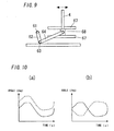
- the handle bar 4 is located so as to extend from the step 1, as shown in Fig. 10(a) , the handle bar 4 and the step 1 are synchronized to move each other in the same phase when the step 1 rotates with respect to the platform 3.
- the handle bar 4 and the step 1 may be moved each other in the opposite phase when the step 1 rotates with respect to the platform 3.
- a handle bar driving means 6 drives the handle bar 4.
- the case rotating the handle bar 4, the case moving the handle bar 4 in a vertical direction, and the case moving the handle bar 4 in a front-back direction or a left-and-right direction are explained.
- a motor (not shown) of the handle bar driving means 6 is driven, and a rotative force is transmitted to a crankshaft 61 via a reducer (not shown), and a crankarm 62 is rotated.
- a crankpin 63 connects an end of the crankarm 62 with one end of a link 64, and the other end of the link 64 is connected to an intermediate position of the handle bar 4.
- a bottom head of the handle bar 4 is pivotally supported by the platform 3, and the handle bar 4 is rotated by the rotation of the crankarm 62 via the link 64.
- a motor 60 of the handle bar driving means 6 is driven, and the crankshaft 61 and the crankarm 62 are rotated via a reducer (item G is a gear box).
- An end of the crankarm 62 is pivotally supported by a bottom head of the handle bar 4, and the handle bar 4 is configured so as to move in a vertical direction by the rotation of the crankarm 62.
- Item 62a is a connection member connecting the end of the crankarm 62 and the bottom head of the handle bar 4.
- a gear wheel is mounted in the output shaft 60a of the motor 60, and gears a pinion 65.
- a rack 66 is moved in a motion direction by the rotation of the pinion 65.
- a bottom head of the handle bar 4 is fixed into the rack 66, and the handle bar 4 is configured so as to move in a front-back direction or a left-and-right direction by the rotation of the motor 60.
- the motor 60 of the handle bar driving means 6 is driven, and the crankshaft 61 and the crankarm 62 are rotated via a reducer.
- An end of the crankarm 62 is pivotally supported by a movement member 68 which can move a guide 67 located along a front-back direction or a left-and-right direction.
- a bottom head of the handle bar 4 is fixed into the movement member 68, and the handle bar 4 is configured so as to move in a front-back direction or a left-and-right direction by the rotation of the crankarm 62.
- the handle bar 4 is located to be movable with respect to the platform 3, and thus the user can perform not only a passive exercise by the above-mentioned step 1 but a passive exercise by the handle bar 4 or a passive exercise by the combination of the step 1 and the handle bar 4.
- the auxiliary exercise equipment may be controlled by changing a stroke of sliding and reciprocating or rotation of the step 1. Or, the auxiliary exercise equipment may be controlled by changing a rotative motion, a motion in a vertical direction, and a motion in a front-back direction or a left-and-right direction of the handle bar 4. For this reason, the user can control a dynamic level of the passive exercise via the switch 5 operation while griping the handle bar 4.
- the auxiliary exercise equipment may be configured so that different types of a passive exercise can be changed by the switch 5 operation.
- the types are a passive exercise performed by step 1, a passive exercise performed by the handle bar 4, and a passive exercise performed by the combination of the step 1 and the handle bar 4.
- the user can change the types of the passive exercise while griping the handle bar 4.
Landscapes
- Health & Medical Sciences (AREA)
- General Health & Medical Sciences (AREA)
- Physical Education & Sports Medicine (AREA)
- Pain & Pain Management (AREA)
- Epidemiology (AREA)
- Rehabilitation Therapy (AREA)
- Life Sciences & Earth Sciences (AREA)
- Animal Behavior & Ethology (AREA)
- Public Health (AREA)
- Veterinary Medicine (AREA)
- Vascular Medicine (AREA)
- Cardiology (AREA)
- Rehabilitation Tools (AREA)
Applications Claiming Priority (1)
| Application Number | Priority Date | Filing Date | Title |
|---|---|---|---|
| PCT/JP2008/056437 WO2009122554A1 (ja) | 2008-03-31 | 2008-03-31 | 運動補助装置 |
Publications (1)
| Publication Number | Publication Date |
|---|---|
| EP2269554A1 true EP2269554A1 (de) | 2011-01-05 |
Family
ID=41134975
Family Applications (1)
| Application Number | Title | Priority Date | Filing Date |
|---|---|---|---|
| EP08739550A Withdrawn EP2269554A1 (de) | 2008-03-31 | 2008-03-31 | Körperübungen unterstützendes gerät |
Country Status (6)
| Country | Link |
|---|---|
| US (1) | US20110015551A1 (de) |
| EP (1) | EP2269554A1 (de) |
| JP (1) | JPWO2009122554A1 (de) |
| KR (1) | KR20100132522A (de) |
| CN (1) | CN101980683A (de) |
| WO (1) | WO2009122554A1 (de) |
Families Citing this family (10)
| Publication number | Priority date | Publication date | Assignee | Title |
|---|---|---|---|---|
| KR20100085104A (ko) * | 2007-10-31 | 2010-07-28 | 파나소닉 전공 주식회사 | 운동 보조 기기 |
| KR20140103577A (ko) * | 2013-02-18 | 2014-08-27 | 주식회사 앞썬아이앤씨 | 재활 치료용 운동장치 |
| KR101553066B1 (ko) * | 2014-09-05 | 2015-09-15 | 주식회사 에스피글로벌 | 발끝 치기용 운동 기구 |
| JP6281510B2 (ja) * | 2015-03-19 | 2018-02-21 | トヨタ自動車株式会社 | 倒立二輪車 |
| CN107539410A (zh) * | 2017-09-30 | 2018-01-05 | 温州赫驰科技有限公司 | 一种自动折叠脚踏板 |
| JP2019092638A (ja) * | 2017-11-20 | 2019-06-20 | 大東電機工業株式会社 | 立ち乗り型運動装置 |
| CN110251363B (zh) * | 2019-06-07 | 2021-09-14 | 奥佳华智能健康科技集团股份有限公司 | 一种拉筋脚机 |
| CN112169260A (zh) * | 2019-07-04 | 2021-01-05 | 北京力泰克科技有限公司 | 康复用椭圆机及其脚踏板机构 |
| PL246950B1 (pl) * | 2022-10-14 | 2025-04-07 | Politechnika Rzeszowska Im Ignacego Lukasiewicza | Urządzenie do ćwiczeń kończyn dolnych |
| PL246951B1 (pl) * | 2022-10-14 | 2025-04-07 | Politechnika Rzeszowska Im Ignacego Lukasiewicza | Urządzenie do ćwiczeń kończyn dolnych |
Family Cites Families (12)
| Publication number | Priority date | Publication date | Assignee | Title |
|---|---|---|---|---|
| JPS5623561U (de) * | 1979-08-02 | 1981-03-03 | ||
| JPS6483272A (en) * | 1987-09-24 | 1989-03-29 | Kenko No Kikakushiya Kk | Sporting equipment of twisting type |
| CA2133251C (en) * | 1993-09-30 | 1999-01-12 | Gary D. Piaget | Striding exerciser with upwardly curved tracks |
| JP2917128B2 (ja) | 1996-08-08 | 1999-07-12 | 谷 白糸 | 歩行体験装置 |
| US6908416B2 (en) * | 1998-07-23 | 2005-06-21 | Unisen, Inc. | Exercise and therapeutic trainer |
| US7025710B2 (en) * | 1998-07-23 | 2006-04-11 | Unisen, Inc. | Elliptical exercise device and arm linkage |
| JP3080069U (ja) * | 2001-03-07 | 2001-09-14 | 海濱 郭 | 歩行運動機 |
| US20040214691A1 (en) * | 2001-11-20 | 2004-10-28 | Karen Gottlieb-Myers | Pogo sticks |
| USD493497S1 (en) * | 2002-04-15 | 2004-07-27 | J. M. Originals, Inc. | Pogo stick |
| JP3091970U (ja) * | 2002-08-07 | 2003-02-21 | 雷仁貿易有限公司 | トレーニング用器具 |
| JP2007167625A (ja) * | 2005-11-28 | 2007-07-05 | Daito Denki Kogyo Kk | 運動装置 |
| JP3132377U (ja) * | 2007-03-26 | 2007-06-07 | 晋 橋本 | 運動器具 |
-
2008
- 2008-03-31 WO PCT/JP2008/056437 patent/WO2009122554A1/ja not_active Ceased
- 2008-03-31 US US12/736,304 patent/US20110015551A1/en not_active Abandoned
- 2008-03-31 JP JP2010505212A patent/JPWO2009122554A1/ja active Pending
- 2008-03-31 EP EP08739550A patent/EP2269554A1/de not_active Withdrawn
- 2008-03-31 KR KR1020107022749A patent/KR20100132522A/ko not_active Ceased
- 2008-03-31 CN CN200880128387.1A patent/CN101980683A/zh active Pending
Non-Patent Citations (1)
| Title |
|---|
| See references of WO2009122554A1 * |
Also Published As
| Publication number | Publication date |
|---|---|
| CN101980683A (zh) | 2011-02-23 |
| WO2009122554A1 (ja) | 2009-10-08 |
| KR20100132522A (ko) | 2010-12-17 |
| US20110015551A1 (en) | 2011-01-20 |
| JPWO2009122554A1 (ja) | 2011-07-28 |
Similar Documents
| Publication | Publication Date | Title |
|---|---|---|
| EP2269554A1 (de) | Körperübungen unterstützendes gerät | |
| KR101204809B1 (ko) | 운동 보조 장치 | |
| US8192329B2 (en) | Exercise aiding apparatus | |
| WO2009081935A1 (ja) | 運動補助装置 | |
| CN101835446A (zh) | 运动辅助装置 | |
| WO2009122556A1 (ja) | 運動補助装置 | |
| JPWO2009084574A1 (ja) | 他動運動機器 | |
| US20110021956A1 (en) | Exercise assisting device | |
| JP2008154879A (ja) | 運動補助装置 | |
| KR101208815B1 (ko) | 관절 운동기구 | |
| EP1834620B1 (de) | Vorrichtung zur fussoszillation und zur durchblutungsanregung | |
| CN111228743B (zh) | 一种关节活动辅助装置 | |
| HK1154482A (en) | Auxiliary exercise equipment | |
| JP2008289869A (ja) | 運動補助装置 | |
| JP5149960B2 (ja) | 運動補助装置 | |
| HK1155058A (en) | Exercise aiding apparatus | |
| JP2008264293A (ja) | 運動補助装置 | |
| HK1148189A (en) | Exercise auxiliary equipment | |
| HK1155354A (en) | Exercise assisting device | |
| HK1155057A (en) | Exercise assisting device | |
| HK1151453A (en) | Passive exercise equipment used in standing position | |
| JP2008264292A (ja) | 運動補助装置 |
Legal Events
| Date | Code | Title | Description |
|---|---|---|---|
| PUAI | Public reference made under article 153(3) epc to a published international application that has entered the european phase |
Free format text: ORIGINAL CODE: 0009012 |
|
| 17P | Request for examination filed |
Effective date: 20101021 |
|
| AK | Designated contracting states |
Kind code of ref document: A1 Designated state(s): AT BE BG CH CY CZ DE DK EE ES FI FR GB GR HR HU IE IS IT LI LT LU LV MC MT NL NO PL PT RO SE SI SK TR |
|
| AX | Request for extension of the european patent |
Extension state: AL BA MK RS |
|
| DAX | Request for extension of the european patent (deleted) | ||
| RAP1 | Party data changed (applicant data changed or rights of an application transferred) |
Owner name: PANASONIC CORPORATION |
|
| STAA | Information on the status of an ep patent application or granted ep patent |
Free format text: STATUS: THE APPLICATION HAS BEEN WITHDRAWN |
|
| 18W | Application withdrawn |
Effective date: 20120824 |