EP2266435B1 - Öffnungs- und Schließvorrichtung einer Ausziehführung und Ausziehführung - Google Patents
Öffnungs- und Schließvorrichtung einer Ausziehführung und Ausziehführung Download PDFInfo
- Publication number
- EP2266435B1 EP2266435B1 EP10166313.6A EP10166313A EP2266435B1 EP 2266435 B1 EP2266435 B1 EP 2266435B1 EP 10166313 A EP10166313 A EP 10166313A EP 2266435 B1 EP2266435 B1 EP 2266435B1
- Authority
- EP
- European Patent Office
- Prior art keywords
- opening
- closing device
- guide
- driver
- pull
- Prior art date
- Legal status (The legal status is an assumption and is not a legal conclusion. Google has not performed a legal analysis and makes no representation as to the accuracy of the status listed.)
- Active
Links
- 230000007246 mechanism Effects 0.000 claims description 11
- 239000012190 activator Substances 0.000 claims description 10
- 238000006073 displacement reaction Methods 0.000 claims description 6
- 238000013016 damping Methods 0.000 claims description 2
- 230000008878 coupling Effects 0.000 description 6
- 238000010168 coupling process Methods 0.000 description 6
- 238000005859 coupling reaction Methods 0.000 description 6
- 238000004146 energy storage Methods 0.000 description 6
- 238000003780 insertion Methods 0.000 description 5
- 230000037431 insertion Effects 0.000 description 5
- 238000000034 method Methods 0.000 description 2
- 230000008569 process Effects 0.000 description 2
- 230000001960 triggered effect Effects 0.000 description 2
- 230000004913 activation Effects 0.000 description 1
- 230000008901 benefit Effects 0.000 description 1
- 238000000605 extraction Methods 0.000 description 1
Images


Classifications
-
- A—HUMAN NECESSITIES
- A47—FURNITURE; DOMESTIC ARTICLES OR APPLIANCES; COFFEE MILLS; SPICE MILLS; SUCTION CLEANERS IN GENERAL
- A47B—TABLES; DESKS; OFFICE FURNITURE; CABINETS; DRAWERS; GENERAL DETAILS OF FURNITURE
- A47B88/00—Drawers for tables, cabinets or like furniture; Guides for drawers
- A47B88/40—Sliding drawers; Slides or guides therefor
- A47B88/453—Actuated drawers
- A47B88/46—Actuated drawers operated by mechanically-stored energy, e.g. by springs
- A47B88/47—Actuated drawers operated by mechanically-stored energy, e.g. by springs having both self-opening and self-closing mechanisms which interact with each other
-
- A—HUMAN NECESSITIES
- A47—FURNITURE; DOMESTIC ARTICLES OR APPLIANCES; COFFEE MILLS; SPICE MILLS; SUCTION CLEANERS IN GENERAL
- A47B—TABLES; DESKS; OFFICE FURNITURE; CABINETS; DRAWERS; GENERAL DETAILS OF FURNITURE
- A47B88/00—Drawers for tables, cabinets or like furniture; Guides for drawers
- A47B88/40—Sliding drawers; Slides or guides therefor
- A47B88/453—Actuated drawers
- A47B88/46—Actuated drawers operated by mechanically-stored energy, e.g. by springs
- A47B88/463—Actuated drawers operated by mechanically-stored energy, e.g. by springs self-opening
Definitions
- the present invention relates to an opening and closing device of a pull-out, in particular for drawers, according to the preamble of claim 1 and a pull-out.
- Generic opening and closing devices for pull-out guides are known in numerous designs from the prior art such as from the DE 20 2005 009 860 U1 ,
- a driver which is displaceable along an integrally formed on a guide housing guide, coupled to a locking mechanism arranged in a force storage such that releases the driver by pressing the drawer in the direction of the furniture body of the locking mechanism and the biased energy storage pushes the drawer in the opening direction , If the drawer is subsequently pushed back into the furniture carcass, the energy store is again pretensioned and the catch is locked in place via the latching mechanism in a closed position biasing the energy store.
- opening and closing devices can be pulled out directly from the furniture body contrary to the opening type described above.
- this movement results in an "emergency opening", wherein in the subsequent closing movement, the opening and closing device must be reset.
- This reset is done with an increased effort connected and also generates unwanted switching noise.
- both the emergency opening and the reset with repeated use can lead to damage of the opening and closing device.
- Object of the present invention is to provide an opening and closing device of a pull-out with a slidably arranged in a furniture body furniture part can be opened both by pressing the furniture part in the insertion direction and by pulling in the withdrawal direction without accepting the disadvantages mentioned above.
- control cam is integrally formed on a component which is displaceably arranged in the guide housing in the displacement direction of the pull-out guide and can be displaced in the guide housing in the extension direction in the guide housing in the closed position.
- the component is spring-loaded arranged on the guide housing.
- This spring loading is effected in particular by a second energy accumulator designed as a tension spring, via which the component is coupled to the guide housing. Trained as a tension spring second energy storage is used at the same time open by train furniture part as a self-closing during the subsequent closing of the furniture part.
- a damper for damping an insertion movement of the opening and closing device is arranged on the housing, so that an excessive impact of the furniture part during insertion into the furniture body is effectively prevented.
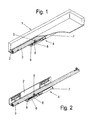
- FIGS. 1 to 3 is denoted by the reference numeral 4 in total a variant of an opening and closing device according to the invention
- the in the in the FIG. 2 is arranged on a variant of a pull-out guide, which on movably arranged on a furniture body furniture parts 1, as in FIG. 1 is shown, in particular drawers and the like is used.
- the pull-out guide itself consists of a fixed to a furniture body guide rail 2 to which the opening and closing device 4 is attached and a movable on the guide rail 2 running rail 3, to which an activator 5 is fixed, with which the opening and closing device 4 during a closing or opening operation of the movable furniture part 1 can be activated.
- the pull-out guide with the opening and closing device 4 arranged thereon serves for the storage of drawers 1, as in FIG FIG. 1 shown, but can also be used for other sliding elements such as sliding holders, shelves or the like.
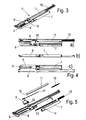
- the opening and closing device 4 has an ejection mechanism, with a displaceable by an activator 5 driver 8, which is in a guide housing 6 along a preferably L-shaped guide 9 and slidably fixed in an open and a closed position.
- the ejection mechanism has a latching mechanism with a control cam 18 formed in the guide housing 6 in the direction of displacement of the pull-out guide of the displaceably arranged component 11 and a control element 16 displaceable along this control cam 18 and coupled to the driver 8, around the driver 8 to fix against the force of a first energy storage 15 in the closed position.
- the guide 9 is formed in the guide housing 6 as a backdrop-shaped recess in which the driver 8 is slidably guided.
- the driver 8 has a receptacle 12 for the attached to the running rail 3 activator 5.
- Opening direction of the pull-out guide is free.
- the running rail 3 can be moved further into its opening end position.
- control 16 is guided by the movement of the driver 8 away from the short L-piece of the guide 9 in the closing direction of the pull-out in a recess 19 of the control cam 18, a retraction of the driver 8 prevented in the opening direction.
- the component 11 is coupled to the control curve 18 via a second power storage 10 to the guide housing 6, so that upon a displacement of the component 11 in the opening or closing direction of the pull-out of the preferably designed as a tension spring second energy storage device 10 or is relaxed.
- the spring force of the second energy accumulator 10 is greater than the spring force of the first energy accumulator 15 so that the component 11 is not moved in the extension direction by the force exerted by the first energy accumulator 15 via the control element 16 on the component 11.
- a latching is also conceivable, which holds the component in the closed position and permits a displacement of the component 11 from a predetermined exertion of force on the component 11.
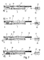
- FIGS. 6a to d the course of motion is shown in a sequence brought about by pulling on the movable part in the extension direction and in the FIGS. 7a to d the sequence of movements in a represented by pressing against the movable furniture part in the closing direction and then releasing.
- FIG. 6a shows the position of the opening and closing device 4 in the closed position, in which the control element 16 is positioned with a provided at the top of the control element 16 bent nose 17 in the recess 19 of the control cam 18.
- the control element 16 becomes out of the depression 19, as in FIG Figure 7a shown, moved out and can be moved along the control cam 18 in the opening direction of the pull-out. Due to this free displacement of the control element 16, the first energy accumulator 15 can relax and thus pushes the drawer 1 partially out of the furniture body.
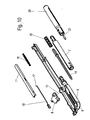
- FIGS. 8 to 10 shown embodiment of the opening and closing device 4 is additionally coupled to the housing 7 'a damper 20, with a retraction movement of the drawer 1 is effectively damped to dampen a striking of the drawer 1 in the furniture body.
- a coupling rod 21 of the damper 20 is coupled to the rod 14, so that movement of the rod 14 in the insertion direction is damped by the damper 20.
Description
- Die vorliegende Erfindung betrifft eine Öffnungs- und Schließvorrichtung einer Ausziehführung, insbesondere für Schubkästen, gemäß dem Oberbegriff des Anspruchs 1 sowie einer Ausziehführung.
- Gattungsgemäße Öffnungs- und Schließvorrichtungen für Ausziehführungen sind in zahlreichen Ausführungen aus dem Stand der Technik bekannt wie z.B. aus der
DE 20 2005 009 860 U1 . Bei diesen wird ein Mitnehmer, der entlang einer an einem Führungsgehäuse angeformten Führung verschiebbar ist, mit einem in einem Rastmechanismus angeordneten Kraftspeicher derart gekoppelt, dass durch Drücken des Schubkastens in Richtung des Möbelkorpus der Rastmechanismus den Mitnehmer freigibt und der vorgespannte Kraftspeicher den Schubkasten in Öffnungsrichtung drückt. Wird der Schubkasten anschließend wieder in den Möbelkorpus hinein geschoben, wird der Kraftspeicher wieder vorgespannt und der Mitnehmer über den Rastmechanismus in einer den Kraftspeicher vorspannenden Schließstellung verrastet. - Des Weiteren können diese Öffnungs- und Schließvorrichtungen entgegen der oben beschriebenen Öffnungsart auch direkt aus dem Möbelkorpus herausgezogen werden. Diese Bewegung resultiert jedoch in eine "Notöffnung", wobei bei der sich anschließenden Schließbewegung die Öffnungs- und Schließvorrichtung zurückgesetzt werden muss. Dieses Zurücksetzen ist mit einem erhöhten Kraftaufwand verbunden und erzeugt zusätzlich unerwünschte Schaltgeräusche. Außerdem kann sowohl die Notöffnung als auch das Zurücksetzen bei mehrmaliger Nutzung zu einer Beschädigung der Öffnungs- und Schließvorrichtung führen.
- Aufgabe der vorliegenden Erfindung ist es, eine Öffnungs- und Schließvorrichtung einer Ausziehführung bereit zu stellen, mit der ein in einem Möbelkorpus verschiebbar angeordnetes Möbelteil sowohl durch Drücken des Möbelteils in Einschubrichtung als auch durch Zug in Ausziehrichtung ohne Inkaufnahme der oben genannten Nachteile geöffnet werden kann.
- Diese Aufgabe wird durch eine Öffnungs- und Schließvorrichtung einer Ausziehführung mit den Merkmalen des Anspruchs 1 sowie durch eine Ausziehführung mit den Merkmalen des Anspruchs 9 gelöst.
- Erfindungsgemäß ist die Steuerkurve an einem in dem Führungsgehäuse in Verschieberichtung der Ausziehführung verschiebbar angeordneten Bauteil angeformt und mit in der Schließposition fixiertem Steuerelement in Auszugsrichtung in dem Führungsgehäuse verschiebbar. Dadurch ist dem Benutzer ermöglicht, das mit dieser Öffnungs- und Schließvorrichtung versehene Möbelteil ohne Ausnutzung des integrierten Ausstoßmechanismus zu öffnen. Eine besondere Aktivierung oder Umschaltung zwischen den verschiedenen Öffnungsarten ist hier nicht erforderlich. Alternativ zum direkten Ausziehen des Möbelteils steht der Ausstoßmechanismus bei jeder Öffnung des Möbelteils wahlweise zur Verfügung.
- Gemäß einer besonderen Ausführungsvariante ist das Bauteil federbelastet an den Führungsgehäuse angeordnet. Diese Federbelastung erfolgt insbesondere durch einen als Zugfeder ausgebildeten zweiten Kraftspeicher, über den das Bauteil an das Führungsgehäuse angekoppelt ist. Der als Zugfeder ausgebildete zweite Kraftspeicher dient bei durch Zug geöffnetem Möbelteil gleichzeitig auch als Selbsteinzug beim anschließenden Schließvorgang des Möbelteils.
- Gemäß einer weiteren Ausführungsvariante ist an dem Gehäuse ein Dämpfer zur Dämpfung einer Einschubbewegung der Öffnungs- und Schließvorrichtung angeordnet, sodass ein zu starkes Aufprallen des Möbelteils beim Einschieben in den Möbelkorpus wirksam verhindert ist.
- Nachfolgend werden Ausführungsbeispiele der Erfindung anhand der beiliegenden Zeichnungen näher erläutert.
- Es zeigen:
- Figur 1
- eine schematische perspektivische Darstellung einer an einem Schubkasten angeordneten Ausführungsform einer erfindungsgemäßen Ausziehführung,
- Figur 2
- eine schematische perspektivische Darstellung einer Ausführungsform der Ausziehführung mit daran angeordneter Öffnungs- und Schließvorrichtung,
- Figur 3
- eine schematische perspektivische Darstellung der Öffnungs- und Schließvorrichtung aus
Figur 2 , - Figuren 4a bis c
- verschiedene Ansichten der Öffnungs- und Schließvorrichtung aus
Figur 3 , - Figur 5
- eine schematische Explosionsdarstellung der Öffnungs- und Schließvorrichtung aus
Figur 3 , - Figuren 6a bis d
- eine schematische Darstellung des Bewegungsablaufes eines durch Zug eingeleiteten Öffnungsvorgangs,
- Figuren 7a bis d
- eine schematischen Darstellung des Bewegungsablaufes eines durch Drücken eingeleiteten Öffnungsvorgangs,
- Figur 8
- eine schematische perspektivische Darstellung einer weiteren Ausführungsform einer erfindungsgemäßen Ausziehführung mit daran angeordneter Öffnungs- und Schließvorrichtung,
- Figur 9
- eine schematische perspektivische Darstellung der Öffnungs- und Schließvorrichtung aus
Figur 8 und - Figur 10
- eine schematische perspektivische Explosionsdarstellung der Öffnungs- und Schließvorrichtung aus
Figur 8 . - In den
Figuren 1 bis 3 ist mit den Bezugszeichen 4 insgesamt eine Ausführungsvariante einer erfindungsgemäßen Öffnungs- und Schließvorrichtung bezeichnet, die in der in derFigur 2 gezeigten Darstellung an einer Ausführungsvariante einer Ausziehführung angeordnet ist, welche an beweglich an einem Möbelkorpus angeordneten Möbelteilen 1, wie inFigur 1 gezeigt ist, insbesondere Schubkästen und dergleichen eingesetzt wird. Die Ausziehführung selbst besteht aus einer an einem Möbelkorpus festgelegten Führungsschiene 2, an der die Öffnungs- und Schließvorrichtung 4 befestigt ist sowie einer auf der Führungsschiene 2 verfahrbaren Laufschiene 3, an der ein Aktivator 5 befestigt ist, mit dem die Öffnungs- und Schließvorrichtung 4 während eines Schließ- oder Öffnungsvorgangs des beweglichen Möbelteils 1 aktivierbar ist. Die Ausziehführung mit der daran angeordneten Öffnungs- und Schließvorrichtung 4 dient der Lagerung von Schubkästen 1, wie inFigur 1 gezeigt, ist aber auch für andere verschiebbare Elemente wie Schiebehalter, Ablagen oder dergleichen einsetzbar. - Die Öffnungs- und Schließvorrichtung 4 weist einen Ausstoßmechanismus auf, mit einem durch einen Aktivator 5 verschiebbaren Mitnehmer 8, der in einem Führungsgehäuse 6 entlang einer vorzugsweise L-förmig ausgebildeten Führung 9 verschiebbar und in einer Öffnungs- und einer Schließposition fixierbar ist. Zur Fixierung des Mitnehmers 8 weist der Ausstoßmechanismus einen Rastmechanismus mit einer in dem Führungsgehäuse 6 in Verschieberichtung der Ausziehführung der verschiebbar angeordneten Bauteil 11 angeformten Steuerkurve 18 auf sowie einem entlang dieser Steuerkurve 18 verschiebbaren und mit dem Mitnehmer 8 gekoppelten Steuerelement 16 auf, um den Mitnehmer 8 entgegen der Kraft eines ersten Kraftspeichers 15 in der Schließposition zu fixieren.
- Wie in den
Figuren 3 bis 5 gezeigt, ist die Führung 9 in dem Führungsgehäuse 6 als kulissenförmige Aussparung ausgebildet, in der der Mitnehmer 8 verschiebbar geführt ist. Der Mitnehmer 8 weist eine Aufnahme 12 für den an der Laufschiene 3 befestigten Aktivator 5 auf. - Zur Fixierung des Mitnehmers 8 in der Öffnungsposition fährt der Mitnehmer 8 mit einem vorderen Ende in das kurze L-Stück der Führung 9 ein, wodurch der Mitnehmer 8 quer zur Bewegungsrichtung der Laufschiene 3 und somit auch quer zur Bewegungsrichtung des Aktivators 5 wegkippt und dadurch den Aktivator 5 in
- Öffnungsrichtung der Ausziehführung frei gibt. Dadurch kann die Laufschiene 3 weiter in ihre Öffnungsendstellung verschoben werden.
- Zur Fixierung des Mitnehmers in der Schließposition wird das mit dem Mitnehmer 8 gekoppelte Steuerelement 16 durch die Bewegung des Mitnehmers 8 weg von dem kurzem L-Stück der Führung 9 in Schließrichtung der Ausziehführung in eine Senke 19 der Steuerkurve 18 geführt, die ein Zurückfahren des Mitnehmers 8 in Öffnungsrichtung verhindert.
- Gleichzeitig wird mit der Bewegung des Mitnehmers 8 in die Schließposition der erste Kraftspeicher 15, der in einem Gehäuse 7 gelagert ist, das an dem Führungsgehäuse 6 über ein Koppelstück 13 befestigt ist, über eine an den Mitnehmer 8 gekoppelte Stange 14 gegen eine Innenstirnseite des vorzugsweise zylinderförmig ausgebildeten Gehäuses 7 gedrückt und dadurch vorgespannt.
- Wie in
Figur 5 des Weiteren zu erkennen ist, ist das Bauteil 11 mit der Steuerkurve 18 über einen zweiten Kraftspeicher 10 an das Führungsgehäuse 6 angekoppelt, sodass bei einer Verschiebung des Bauteils 11 in Öffnungs- oder Schließrichtung der Ausziehführung der vorzugsweise als Zugfeder ausgebildete zweiter Kraftspeicher 10 ge- bzw. entspannt wird. Die Federkraft des zweiten Kraftspeichers 10 ist dabei größer als die Federkraft des ersten Kraftspeichers 15, damit das Bauteil 11 nicht durch den von dem ersten Kraftspeicher 15 über das Steuerelement 16 auf das Bauteil 11 ausgeübte Kraft in Auszugsrichtung bewegt wird. Alternativ zur Koppelung des Bauteils 11 mit dem Führungsgehäuse über den zweiten Kraftspeicher 10 ist auch eine Verrastung denkbar, die das Bauteil in der Schließposition hält und ein Verschieben des Bauteils 11 ab einer vorbestimmten Kraftausübung auf das Bauteil 11 zulässt. - Die Funktionsweise der Öffnungs- und Schließvorrichtung 4 wird nachfolgend mit Bezug auf die
Figuren 6 und7 näher erläutert. Dabei ist in denFiguren 6a bis d der Bewegungsablauf bei einer durch Zug an dem beweglichen Teil in Auszugsrichtung bewirkten Ablauf gezeigt und in denFiguren 7a bis d der Bewegungsablauf bei einer durch Drücken gegen das bewegliche Möbelteil in Schließrichtung und anschließendes Loslassen dargestellt. -
Figur 6a zeigt die Position der Öffnungs- und Schließvorrichtung 4 in der Schließstellung, bei der das Steuerelement 16 mit einem an der Spitze des Steuerelementes 16 vorgesehenen umgebogenen Nase 17 in der Senke 19 der Steuerkurve 18 positioniert ist. Zieht nun Benutzer ein das beispielsweise als Schubkasten 1 ausgebildete Möbelteil aus dem Möbelkorpus heraus, ohne vorher den Schubkasten in Einschubrichtung gedrückt zu haben, so verbleibt das Steuerelement 16 während des gesamten Auszugvorgangs, wie gezeigt in den Detailausschnitten derFiguren 6a bis d, in der Senke 19 der Steuerkurve 18. Wie in denFiguren 6b bis 6d zu erkennen ist, wird mit der Bewegung des Mitnehmers 8 in eine den Aktivator freigebende Öffnungsposition des Mitnehmers 8 der zweite Kraftspeicher 10 durch die Kopplung des Mitnehmers 8 und des Bauteils 11 über das in der Senke 19 der Steuerkurve 18 verhakte Steuerelement 16 gespannt. Bei der anschließenden Schließbewegung des Schubkastens 1 zurück in den Möbelkorpus wird durch den gespannten zweiten Kraftspeicher 10 unmittelbar nach der durch die Ankopplung des Aktivators 5 ausgelöste Freigabe des Mitnehmers 8 aus der Öffnungsposition ein Selbsteinzug, bewirkt durch die Vorspannung des zweiten Kraftspeichers 10, ausgelöst. - Wird dagegen die Öffnung des Schubkastens 1 durch Drücken des Schubkasten 1 in Schließrichtung eingeleitet, so wird das Steuerelement 16 aus der Senke 19, wie in
Figur 7a gezeigt, herausbewegt und kann entlang der Steuerkurve 18 in Öffnungsrichtung der Ausziehführung verschoben werden. Bedingt durch diese freie Verschiebbarkeit des Steuerelementes 16 kann sich der erste Kraftspeicher 15 entspannen und drückt damit den Schubkasten 1 teilweise aus dem Möbelkorpus heraus. Dabei wird der Mitnehmer 8, wie in denFiguren 7b, c und d gezeigt, in das kurze L-Stück der Führung 9 eingeschoben, kippt hierbei quer zur Öffnungsrichtung weg und gibt damit den Aktivator 5 frei, sodass der Schubkasten 1 in seine Endöffnungsstellung weiter verfahrbar ist. Beim anschließenden Wiedereinschieben des Schubkastens 1 in den Möbelkorpus muss dieser soweit gegen den Wiederstand des ersten Kraftspeichers 15 in den Möbelkorpus hinein geschoben werden, bis das mit dem Mitnehmer 8 gekoppelte Steuerelement 16 wieder in die Senke 19 der Steuerkurve 18 einfährt und dadurch den Mitnehmer 8 in der Schließstellung verrastet. - Bei der in den
Figuren 8 bis 10 gezeigten Ausführungsvariante der Öffnungs- und Schließvorrichtung 4 ist an das Gehäuse 7' zusätzlich ein Dämpfer 20 gekoppelt, mit dem eine Einzugsbewegung des Schubkastens 1 wirksam abgedämpft wird, um ein Anschlagen des Schubkastens 1 in dem Möbelkorpus abzudämpfen. Dazu ist, wie inFigur 10 zu erkennen ist, eine Koppelstange 21 des Dämpfers 20 mit der Stange 14 gekoppelt, sodass eine Bewegung der Stange 14 in Einschubrichtung durch den Dämpfer 20 abgedämpft wird. -
- 1
- Schubkasten
- 2
- Führungsschiene
- 3
- Laufschiene
- 4
- Öffnungs- und Schließvorrichtung
- 5
- Aktivator
- 6
- Führungsgehäuse
- 7
- Gehäuse
- 7'
- Gehäuse
- 8
- Mitnehmer
- 9
- Führung
- 10
- Kraftspeicher
- 11
- Bauteil
- 12
- Aufnahme
- 13
- Koppelstück
- 14
- Stange
- 15
- Kraftspeicher
- 16
- Steuerelement
- 17
- Nase
- 18
- Steuerkurve
- 19
- Senke
- 20
- Dämpfer
- 21
- Stange
Claims (9)
- Öffnungs- und Schließvorrichtung (4) einer Ausziehführung, insbesondere für Schubkästen (1), aufweisend- einen Ausstoßmechanismus mit einem durch einen Aktivator (5) verschiebbaren Mitnehmer (8), der in einem Führungsgehäuse (6) entlang einer Führung (9) verschiebbar und in einer Öffnungsposition und einer Schließposition fixierbar ist,- wobei der Ausstoßmechanismus einen Rastmechanismus mit einer Steuerkurve (18) und einem entlang der Steuerkurve (18) verschiebbaren und mit dem Mitnehmer (8) gekoppeltem Steuerelement (16) aufweist, um den Mitnehmer (8) entgegen der Kraft eines ersten Kraftspeichers (15) in der Schließposition zu fixieren,
dadurch gekennzeichnet, dassa. die Steuerkurve (18) an einem in dem Führungsgehäuse (6) in Verschieberichtung der Ausziehführung verschiebbar angeordneten Bauteil (11) angeformt ist und mit in der Schließposition fixiertem Steuerelement (16) in Auszugsrichtung in dem Führungsgehäuse (6) verschiebbar ist. - Öffnungs- und Schließvorrichtung (4) nach Anspruch 1, dadurch gekennzeichnet, dass das Bauteil (11) federbelastet an dem Führungsgehäuse (6) angeordnet ist.
- Öffnungs- und Schließvorrichtung (4) nach Anspruch 2, dadurch gekennzeichnet, dass das Bauteil (11) über einen zweiten Kraftspeicher (10) an das Führungsgehäuse (6) angekoppelt ist.
- Öffnungs- und Schließvorrichtung (4) nach Anspruch 3, dadurch gekennzeichnet, dass der zweite Kraftspeicher (10) als Zugfeder ausgebildet ist.
- Öffnungs- und Schließvorrichtung (4) nach Anspruch 3, dadurch gekennzeichnet, dass die von dem zweiten Kraftspeicher (10) auf das Bauteil (11) ausgeübte Kraft stärker ist als die von dem ersten Kraftspeicher (15) in der Schließposition der Ausziehführung (1) auf das Bauteil (11) ausgeübte Kraft.
- Öffnungs- und Schließvorrichtung (4) nach Anspruch 4, dadurch gekennzeichnet, dass an der Öffnungs- und Schließvorrichtung (4) ein Dämpfer (20) zur Dämpfung einer Einschubbewegung angeordnet ist.
- Öffnungs- und Schließvorrichtung (4) nach Anspruch 6, dadurch gekennzeichnet, dass der Dämpfer an dem Gehäuse (7) angeordnet ist.
- Öffnungs- und Schließvorrichtung (4) nach Anspruch 7, dadurch gekennzeichnet, dass der Dämpfer (20) an einem von dem Mitnehmer (8) abgewandten Ende des Gehäuses (7) angeordnet ist.
- Ausziehführung, aufweisend eine an einem Möbelkorpus festlegbare Führungsschiene (2), an der eine Laufschiene (4) direkt oder über eine Mittelschiene geführt, ist, dadurch gekennzeichnet, dass an der Führungsschiene (2) eine Öffnungs- und Schließvorrichtung (4) nach einem der vorhergehenden Ansprüche montiert ist.
Applications Claiming Priority (1)
| Application Number | Priority Date | Filing Date | Title |
|---|---|---|---|
| DE202009004956U DE202009004956U1 (de) | 2009-06-26 | 2009-06-26 | Öffnungs- und Schließvorrichtung einer Ausziehführung und Ausziehführung |
Publications (2)
| Publication Number | Publication Date |
|---|---|
| EP2266435A1 EP2266435A1 (de) | 2010-12-29 |
| EP2266435B1 true EP2266435B1 (de) | 2015-02-25 |
Family
ID=42460970
Family Applications (1)
| Application Number | Title | Priority Date | Filing Date |
|---|---|---|---|
| EP10166313.6A Active EP2266435B1 (de) | 2009-06-26 | 2010-06-17 | Öffnungs- und Schließvorrichtung einer Ausziehführung und Ausziehführung |
Country Status (5)
| Country | Link |
|---|---|
| EP (1) | EP2266435B1 (de) |
| JP (1) | JP5671733B2 (de) |
| DE (1) | DE202009004956U1 (de) |
| ES (1) | ES2535019T3 (de) |
| RU (1) | RU2516158C2 (de) |
Families Citing this family (8)
| Publication number | Priority date | Publication date | Assignee | Title |
|---|---|---|---|---|
| DE102011054441A1 (de) * | 2011-10-12 | 2013-04-18 | Paul Hettich Gmbh & Co. Kg | Öffnungs- und Schließvorrichtung für ein Schubelement |
| DE202012003537U1 (de) * | 2012-04-11 | 2013-07-15 | Grass Gmbh | Vorrichtung zum Öffnen und Schließen eines bewegbaren Möbelteils |
| AT512513B1 (de) * | 2012-07-10 | 2013-09-15 | Blum Gmbh Julius | Antriebsvorrichtung für ein bewegbares Möbelteil |
| AT514065B1 (de) * | 2013-04-12 | 2014-10-15 | Blum Gmbh Julius | Antriebsvorrichtung für ein bewegbares Möbelteil |
| AT16876U1 (de) * | 2014-05-23 | 2020-11-15 | Blum Gmbh Julius | Möbelantrieb |
| AT15245U1 (de) * | 2015-07-07 | 2017-04-15 | Blum Gmbh Julius | Antriebsvorrichtung für ein bewegbares Möbelteil |
| RU199551U1 (ru) * | 2020-06-01 | 2020-09-07 | Общество с ограниченной ответственностью "БОЯРД" | Устройство фиксации и выталкивания подвижной части направляющей для выдвижного элемента мебели |
| RU207355U1 (ru) * | 2021-05-25 | 2021-10-25 | Общество с ограниченной ответственностью "БОЯРД" | Устройство автоматического втягивания и выталкивания подвижной части направляющей для выдвижного элемента мебели |
Family Cites Families (11)
| Publication number | Priority date | Publication date | Assignee | Title |
|---|---|---|---|---|
| JPS56107049U (de) * | 1980-01-18 | 1981-08-20 | ||
| FR2739268B1 (fr) * | 1995-10-03 | 1997-12-19 | Piole | Dispositif d'ouverture-fermeture d'un element mobile par rapport a un bati, et son application aux meubles deplacables a tiroirs |
| DE19935120C2 (de) * | 1999-07-27 | 2001-05-17 | Bulthaup Gmbh & Co | Vorrichtung zum Öffnen und Schließen einer Schublade |
| ITMC20030144A1 (it) * | 2003-12-05 | 2005-06-06 | Compagnucci Spa Ora Compagnucci Ho Lding Spa | Dispositivo per la chiusura automatica ed ammortizzata dei cassetti e delle strutture estraibili per mobili. |
| DE202005009860U1 (de) * | 2004-12-17 | 2006-04-20 | Alfit Ag | Schließ- und Öffnungsvorrichtung für Schubladen |
| DE202004019738U1 (de) * | 2004-12-17 | 2005-03-17 | Alfit Ag Goetzis | Einzugsautomatik für Schubladen mit Schließ- und Öffnungsvorrichtung |
| JP3118277U (ja) * | 2005-11-04 | 2006-01-26 | 金竣企業股▲ふん▼有限公司 | 引出しスライドレールの自動開放装置 |
| AT503576B1 (de) * | 2006-01-31 | 2007-11-15 | Blum Gmbh Julius | Antriebsmechanismus für ein an einem möbel bewegbar gelagertes möbelteil |
| AT503497B1 (de) * | 2006-04-05 | 2012-05-15 | Blum Gmbh Julius | Antriebsmechanismus für ein in oder an einem möbel bewegbar gelagertes möbelteil |
| TWM300487U (en) * | 2006-06-08 | 2006-11-11 | Gslide Corp | Automatic closing device of drawer rail |
| DE202006014002U1 (de) * | 2006-09-08 | 2007-10-25 | Grass Gmbh | Vorrichtung zum Öffnen und/oder Schließen eines Möbels mit einem gegenüber einem feststehenden Möbelkorpus bewegbaren Möbelteil und Möbelbeschlag und Möbel mit einer solchen Vorrichtung |
-
2009
- 2009-06-26 DE DE202009004956U patent/DE202009004956U1/de not_active Expired - Lifetime
-
2010
- 2010-05-24 JP JP2010118451A patent/JP5671733B2/ja not_active Expired - Fee Related
- 2010-06-17 ES ES10166313.6T patent/ES2535019T3/es active Active
- 2010-06-17 EP EP10166313.6A patent/EP2266435B1/de active Active
- 2010-06-21 RU RU2010125030/12A patent/RU2516158C2/ru active
Also Published As
| Publication number | Publication date |
|---|---|
| RU2516158C2 (ru) | 2014-05-20 |
| ES2535019T3 (es) | 2015-05-04 |
| JP2011005243A (ja) | 2011-01-13 |
| RU2010125030A (ru) | 2011-12-27 |
| EP2266435A1 (de) | 2010-12-29 |
| JP5671733B2 (ja) | 2015-02-18 |
| DE202009004956U1 (de) | 2010-11-11 |
Similar Documents
| Publication | Publication Date | Title |
|---|---|---|
| EP2266435B1 (de) | Öffnungs- und Schließvorrichtung einer Ausziehführung und Ausziehführung | |
| DE102009026260B4 (de) | Öffnungs- und Schließvorrichtung | |
| EP2983555B1 (de) | Antriebsvorrichtung für ein bewegbares möbelteil | |
| AT512165B1 (de) | Antriebsvorrichtung für ein bewegbares möbelteil | |
| DE19935120C2 (de) | Vorrichtung zum Öffnen und Schließen einer Schublade | |
| EP3449077B1 (de) | Ausstossvorrichtung für ein bewegbares möbelteil und möbel | |
| EP2174572B1 (de) | Öffnungs- und Schließvorrichtung für ein Schubelement | |
| EP1816927B1 (de) | Ausziehführungsgarnitur für Schubladen | |
| AT508139B1 (de) | Möbelantrieb mit touch-latch-vorrichtung | |
| DE102011054441A1 (de) | Öffnungs- und Schließvorrichtung für ein Schubelement | |
| DE10008350C2 (de) | Vorrichtung zum Öffnen einer Möbelabdeckung, wie z. B. einer Schublade, Tür oder Klappe | |
| DE202009004953U1 (de) | Selbsteinzugsvorrichtung und Auszugsführung | |
| WO2014124833A1 (de) | Auszugsführung für ein bewegbares möbelteil | |
| EP3439505A2 (de) | Möbelantrieb | |
| EP3448204B1 (de) | Ausstossvorrichtung für ein bewegbares möbelteil und möbel | |
| EP2281482B1 (de) | Ausstoßvorrichtung einer Ausziehführung und Ausziehführung | |
| EP2549904B1 (de) | Selbsteinzugsvorrichtung und auszugsführung | |
| EP3145366B1 (de) | Möbelantrieb | |
| DE202013005797U1 (de) | Einzugsvorrichtung, Ausziehführung mit einer Einzugsvorrichtung sowie Möbel mit einer Ausziehführung | |
| DE102010000340A1 (de) | Einzugvorrichtung für Schiebetüren | |
| EP3518707B1 (de) | Einzugsvorrichtung für einen schubladenauszug | |
| DE202009004957U1 (de) | Öffnungsvorrichtung einer Ausziehführung und Ausziehführung | |
| EP3062661B1 (de) | Vorrichtung zum öffnen eines bewegbaren möbelteils | |
| EP3694375B1 (de) | Einzugsvorrichtung und verfahren zum öffnen und schliessen eines bewegbaren möbelteils | |
| DE202010018353U1 (de) | Auszugsführung |
Legal Events
| Date | Code | Title | Description |
|---|---|---|---|
| PUAI | Public reference made under article 153(3) epc to a published international application that has entered the european phase |
Free format text: ORIGINAL CODE: 0009012 |
|
| AK | Designated contracting states |
Kind code of ref document: A1 Designated state(s): AL AT BE BG CH CY CZ DE DK EE ES FI FR GB GR HR HU IE IS IT LI LT LU LV MC MK MT NL NO PL PT RO SE SI SK SM TR |
|
| AX | Request for extension of the european patent |
Extension state: BA ME RS |
|
| 17P | Request for examination filed |
Effective date: 20110201 |
|
| GRAP | Despatch of communication of intention to grant a patent |
Free format text: ORIGINAL CODE: EPIDOSNIGR1 |
|
| INTG | Intention to grant announced |
Effective date: 20140807 |
|
| GRAP | Despatch of communication of intention to grant a patent |
Free format text: ORIGINAL CODE: EPIDOSNIGR1 |
|
| INTG | Intention to grant announced |
Effective date: 20141029 |
|
| GRAS | Grant fee paid |
Free format text: ORIGINAL CODE: EPIDOSNIGR3 |
|
| GRAA | (expected) grant |
Free format text: ORIGINAL CODE: 0009210 |
|
| AK | Designated contracting states |
Kind code of ref document: B1 Designated state(s): AL AT BE BG CH CY CZ DE DK EE ES FI FR GB GR HR HU IE IS IT LI LT LU LV MC MK MT NL NO PL PT RO SE SI SK SM TR |
|
| REG | Reference to a national code |
Ref country code: GB Ref legal event code: FG4D Free format text: NOT ENGLISH |
|
| REG | Reference to a national code |
Ref country code: CH Ref legal event code: EP |
|
| REG | Reference to a national code |
Ref country code: IE Ref legal event code: FG4D Free format text: LANGUAGE OF EP DOCUMENT: GERMAN |
|
| REG | Reference to a national code |
Ref country code: DE Ref legal event code: R096 Ref document number: 502010008944 Country of ref document: DE Effective date: 20150409 |
|
| REG | Reference to a national code |
Ref country code: AT Ref legal event code: REF Ref document number: 711164 Country of ref document: AT Kind code of ref document: T Effective date: 20150415 |
|
| REG | Reference to a national code |
Ref country code: ES Ref legal event code: FG2A Ref document number: 2535019 Country of ref document: ES Kind code of ref document: T3 Effective date: 20150504 |
|
| REG | Reference to a national code |
Ref country code: NL Ref legal event code: VDEP Effective date: 20150225 |
|
| REG | Reference to a national code |
Ref country code: LT Ref legal event code: MG4D |
|
| PG25 | Lapsed in a contracting state [announced via postgrant information from national office to epo] |
Ref country code: LT Free format text: LAPSE BECAUSE OF FAILURE TO SUBMIT A TRANSLATION OF THE DESCRIPTION OR TO PAY THE FEE WITHIN THE PRESCRIBED TIME-LIMIT Effective date: 20150225 Ref country code: NO Free format text: LAPSE BECAUSE OF FAILURE TO SUBMIT A TRANSLATION OF THE DESCRIPTION OR TO PAY THE FEE WITHIN THE PRESCRIBED TIME-LIMIT Effective date: 20150525 Ref country code: SE Free format text: LAPSE BECAUSE OF FAILURE TO SUBMIT A TRANSLATION OF THE DESCRIPTION OR TO PAY THE FEE WITHIN THE PRESCRIBED TIME-LIMIT Effective date: 20150225 Ref country code: HR Free format text: LAPSE BECAUSE OF FAILURE TO SUBMIT A TRANSLATION OF THE DESCRIPTION OR TO PAY THE FEE WITHIN THE PRESCRIBED TIME-LIMIT Effective date: 20150225 Ref country code: FI Free format text: LAPSE BECAUSE OF FAILURE TO SUBMIT A TRANSLATION OF THE DESCRIPTION OR TO PAY THE FEE WITHIN THE PRESCRIBED TIME-LIMIT Effective date: 20150225 |
|
| PG25 | Lapsed in a contracting state [announced via postgrant information from national office to epo] |
Ref country code: GR Free format text: LAPSE BECAUSE OF FAILURE TO SUBMIT A TRANSLATION OF THE DESCRIPTION OR TO PAY THE FEE WITHIN THE PRESCRIBED TIME-LIMIT Effective date: 20150526 Ref country code: IS Free format text: LAPSE BECAUSE OF FAILURE TO SUBMIT A TRANSLATION OF THE DESCRIPTION OR TO PAY THE FEE WITHIN THE PRESCRIBED TIME-LIMIT Effective date: 20150625 Ref country code: LV Free format text: LAPSE BECAUSE OF FAILURE TO SUBMIT A TRANSLATION OF THE DESCRIPTION OR TO PAY THE FEE WITHIN THE PRESCRIBED TIME-LIMIT Effective date: 20150225 |
|
| PG25 | Lapsed in a contracting state [announced via postgrant information from national office to epo] |
Ref country code: NL Free format text: LAPSE BECAUSE OF FAILURE TO SUBMIT A TRANSLATION OF THE DESCRIPTION OR TO PAY THE FEE WITHIN THE PRESCRIBED TIME-LIMIT Effective date: 20150225 |
|
| PG25 | Lapsed in a contracting state [announced via postgrant information from national office to epo] |
Ref country code: DK Free format text: LAPSE BECAUSE OF FAILURE TO SUBMIT A TRANSLATION OF THE DESCRIPTION OR TO PAY THE FEE WITHIN THE PRESCRIBED TIME-LIMIT Effective date: 20150225 Ref country code: RO Free format text: LAPSE BECAUSE OF FAILURE TO SUBMIT A TRANSLATION OF THE DESCRIPTION OR TO PAY THE FEE WITHIN THE PRESCRIBED TIME-LIMIT Effective date: 20150225 Ref country code: EE Free format text: LAPSE BECAUSE OF FAILURE TO SUBMIT A TRANSLATION OF THE DESCRIPTION OR TO PAY THE FEE WITHIN THE PRESCRIBED TIME-LIMIT Effective date: 20150225 Ref country code: SK Free format text: LAPSE BECAUSE OF FAILURE TO SUBMIT A TRANSLATION OF THE DESCRIPTION OR TO PAY THE FEE WITHIN THE PRESCRIBED TIME-LIMIT Effective date: 20150225 Ref country code: CZ Free format text: LAPSE BECAUSE OF FAILURE TO SUBMIT A TRANSLATION OF THE DESCRIPTION OR TO PAY THE FEE WITHIN THE PRESCRIBED TIME-LIMIT Effective date: 20150225 |
|
| REG | Reference to a national code |
Ref country code: DE Ref legal event code: R097 Ref document number: 502010008944 Country of ref document: DE |
|
| PG25 | Lapsed in a contracting state [announced via postgrant information from national office to epo] |
Ref country code: PL Free format text: LAPSE BECAUSE OF FAILURE TO SUBMIT A TRANSLATION OF THE DESCRIPTION OR TO PAY THE FEE WITHIN THE PRESCRIBED TIME-LIMIT Effective date: 20150225 |
|
| PLBE | No opposition filed within time limit |
Free format text: ORIGINAL CODE: 0009261 |
|
| STAA | Information on the status of an ep patent application or granted ep patent |
Free format text: STATUS: NO OPPOSITION FILED WITHIN TIME LIMIT |
|
| PG25 | Lapsed in a contracting state [announced via postgrant information from national office to epo] |
Ref country code: MC Free format text: LAPSE BECAUSE OF FAILURE TO SUBMIT A TRANSLATION OF THE DESCRIPTION OR TO PAY THE FEE WITHIN THE PRESCRIBED TIME-LIMIT Effective date: 20150225 Ref country code: IT Free format text: LAPSE BECAUSE OF NON-PAYMENT OF DUE FEES Effective date: 20150617 |
|
| REG | Reference to a national code |
Ref country code: CH Ref legal event code: PL |
|
| 26N | No opposition filed |
Effective date: 20151126 |
|
| GBPC | Gb: european patent ceased through non-payment of renewal fee |
Effective date: 20150617 |
|
| PG25 | Lapsed in a contracting state [announced via postgrant information from national office to epo] |
Ref country code: SI Free format text: LAPSE BECAUSE OF FAILURE TO SUBMIT A TRANSLATION OF THE DESCRIPTION OR TO PAY THE FEE WITHIN THE PRESCRIBED TIME-LIMIT Effective date: 20150225 Ref country code: LU Free format text: LAPSE BECAUSE OF FAILURE TO SUBMIT A TRANSLATION OF THE DESCRIPTION OR TO PAY THE FEE WITHIN THE PRESCRIBED TIME-LIMIT Effective date: 20150617 |
|
| REG | Reference to a national code |
Ref country code: IE Ref legal event code: MM4A |
|
| REG | Reference to a national code |
Ref country code: FR Ref legal event code: ST Effective date: 20160229 |
|
| PG25 | Lapsed in a contracting state [announced via postgrant information from national office to epo] |
Ref country code: CH Free format text: LAPSE BECAUSE OF NON-PAYMENT OF DUE FEES Effective date: 20150630 Ref country code: LI Free format text: LAPSE BECAUSE OF NON-PAYMENT OF DUE FEES Effective date: 20150630 Ref country code: GB Free format text: LAPSE BECAUSE OF NON-PAYMENT OF DUE FEES Effective date: 20150617 Ref country code: IE Free format text: LAPSE BECAUSE OF NON-PAYMENT OF DUE FEES Effective date: 20150617 |
|
| PGRI | Patent reinstated in contracting state [announced from national office to epo] |
Ref country code: IT Effective date: 20160412 |
|
| PG25 | Lapsed in a contracting state [announced via postgrant information from national office to epo] |
Ref country code: FR Free format text: LAPSE BECAUSE OF NON-PAYMENT OF DUE FEES Effective date: 20150630 |
|
| REG | Reference to a national code |
Ref country code: DE Ref legal event code: R079 Ref document number: 502010008944 Country of ref document: DE Free format text: PREVIOUS MAIN CLASS: A47B0088040000 Ipc: A47B0088400000 |
|
| PG25 | Lapsed in a contracting state [announced via postgrant information from national office to epo] |
Ref country code: MT Free format text: LAPSE BECAUSE OF FAILURE TO SUBMIT A TRANSLATION OF THE DESCRIPTION OR TO PAY THE FEE WITHIN THE PRESCRIBED TIME-LIMIT Effective date: 20150225 |
|
| PG25 | Lapsed in a contracting state [announced via postgrant information from national office to epo] |
Ref country code: SM Free format text: LAPSE BECAUSE OF FAILURE TO SUBMIT A TRANSLATION OF THE DESCRIPTION OR TO PAY THE FEE WITHIN THE PRESCRIBED TIME-LIMIT Effective date: 20150225 Ref country code: HU Free format text: LAPSE BECAUSE OF FAILURE TO SUBMIT A TRANSLATION OF THE DESCRIPTION OR TO PAY THE FEE WITHIN THE PRESCRIBED TIME-LIMIT; INVALID AB INITIO Effective date: 20100617 Ref country code: BG Free format text: LAPSE BECAUSE OF FAILURE TO SUBMIT A TRANSLATION OF THE DESCRIPTION OR TO PAY THE FEE WITHIN THE PRESCRIBED TIME-LIMIT Effective date: 20150225 |
|
| PG25 | Lapsed in a contracting state [announced via postgrant information from national office to epo] |
Ref country code: CY Free format text: LAPSE BECAUSE OF FAILURE TO SUBMIT A TRANSLATION OF THE DESCRIPTION OR TO PAY THE FEE WITHIN THE PRESCRIBED TIME-LIMIT Effective date: 20150225 |
|
| PG25 | Lapsed in a contracting state [announced via postgrant information from national office to epo] |
Ref country code: BE Free format text: LAPSE BECAUSE OF NON-PAYMENT OF DUE FEES Effective date: 20150630 |
|
| PG25 | Lapsed in a contracting state [announced via postgrant information from national office to epo] |
Ref country code: MK Free format text: LAPSE BECAUSE OF FAILURE TO SUBMIT A TRANSLATION OF THE DESCRIPTION OR TO PAY THE FEE WITHIN THE PRESCRIBED TIME-LIMIT Effective date: 20150225 Ref country code: PT Free format text: LAPSE BECAUSE OF FAILURE TO SUBMIT A TRANSLATION OF THE DESCRIPTION OR TO PAY THE FEE WITHIN THE PRESCRIBED TIME-LIMIT Effective date: 20150225 |
|
| PG25 | Lapsed in a contracting state [announced via postgrant information from national office to epo] |
Ref country code: AL Free format text: LAPSE BECAUSE OF FAILURE TO SUBMIT A TRANSLATION OF THE DESCRIPTION OR TO PAY THE FEE WITHIN THE PRESCRIBED TIME-LIMIT Effective date: 20150225 |
|
| PGFP | Annual fee paid to national office [announced via postgrant information from national office to epo] |
Ref country code: TR Payment date: 20210608 Year of fee payment: 12 |
|
| PGFP | Annual fee paid to national office [announced via postgrant information from national office to epo] |
Ref country code: ES Payment date: 20210722 Year of fee payment: 12 |
|
| P01 | Opt-out of the competence of the unified patent court (upc) registered |
Effective date: 20230418 |
|
| PGFP | Annual fee paid to national office [announced via postgrant information from national office to epo] |
Ref country code: DE Payment date: 20230620 Year of fee payment: 14 |
|
| REG | Reference to a national code |
Ref country code: ES Ref legal event code: FD2A Effective date: 20230804 |
|
| PGFP | Annual fee paid to national office [announced via postgrant information from national office to epo] |
Ref country code: AT Payment date: 20230616 Year of fee payment: 14 |
|
| PG25 | Lapsed in a contracting state [announced via postgrant information from national office to epo] |
Ref country code: ES Free format text: LAPSE BECAUSE OF NON-PAYMENT OF DUE FEES Effective date: 20220618 |
|
| PGFP | Annual fee paid to national office [announced via postgrant information from national office to epo] |
Ref country code: IT Payment date: 20230630 Year of fee payment: 14 |
|
| REG | Reference to a national code |
Ref country code: DE Ref legal event code: R084 Ref document number: 502010008944 Country of ref document: DE |