EP2264437B1 - Improved apparatus for measuring the scattered light signals from a liquid sample - Google Patents
Improved apparatus for measuring the scattered light signals from a liquid sample Download PDFInfo
- Publication number
- EP2264437B1 EP2264437B1 EP10166074.4A EP10166074A EP2264437B1 EP 2264437 B1 EP2264437 B1 EP 2264437B1 EP 10166074 A EP10166074 A EP 10166074A EP 2264437 B1 EP2264437 B1 EP 2264437B1
- Authority
- EP
- European Patent Office
- Prior art keywords
- cell
- light
- bore
- scattering
- scattered
- Prior art date
- Legal status (The legal status is an assumption and is not a legal conclusion. Google has not performed a legal analysis and makes no representation as to the accuracy of the status listed.)
- Active
Links
Images


Classifications
-
- G—PHYSICS
- G01—MEASURING; TESTING
- G01N—INVESTIGATING OR ANALYSING MATERIALS BY DETERMINING THEIR CHEMICAL OR PHYSICAL PROPERTIES
- G01N21/00—Investigating or analysing materials by the use of optical means, i.e. using sub-millimetre waves, infrared, visible or ultraviolet light
- G01N21/17—Systems in which incident light is modified in accordance with the properties of the material investigated
- G01N21/47—Scattering, i.e. diffuse reflection
- G01N21/49—Scattering, i.e. diffuse reflection within a body or fluid
- G01N21/51—Scattering, i.e. diffuse reflection within a body or fluid inside a container, e.g. in an ampoule
-
- G—PHYSICS
- G01—MEASURING; TESTING
- G01N—INVESTIGATING OR ANALYSING MATERIALS BY DETERMINING THEIR CHEMICAL OR PHYSICAL PROPERTIES
- G01N21/00—Investigating or analysing materials by the use of optical means, i.e. using sub-millimetre waves, infrared, visible or ultraviolet light
- G01N21/01—Arrangements or apparatus for facilitating the optical investigation
- G01N21/03—Cuvette constructions
- G01N2021/0346—Capillary cells; Microcells
-
- G—PHYSICS
- G01—MEASURING; TESTING
- G01N—INVESTIGATING OR ANALYSING MATERIALS BY DETERMINING THEIR CHEMICAL OR PHYSICAL PROPERTIES
- G01N21/00—Investigating or analysing materials by the use of optical means, i.e. using sub-millimetre waves, infrared, visible or ultraviolet light
- G01N21/17—Systems in which incident light is modified in accordance with the properties of the material investigated
- G01N21/47—Scattering, i.e. diffuse reflection
- G01N2021/4704—Angular selective
- G01N2021/4709—Backscatter
-
- G—PHYSICS
- G01—MEASURING; TESTING
- G01N—INVESTIGATING OR ANALYSING MATERIALS BY DETERMINING THEIR CHEMICAL OR PHYSICAL PROPERTIES
- G01N21/00—Investigating or analysing materials by the use of optical means, i.e. using sub-millimetre waves, infrared, visible or ultraviolet light
- G01N21/17—Systems in which incident light is modified in accordance with the properties of the material investigated
- G01N21/47—Scattering, i.e. diffuse reflection
- G01N21/49—Scattering, i.e. diffuse reflection within a body or fluid
- G01N21/51—Scattering, i.e. diffuse reflection within a body or fluid inside a container, e.g. in an ampoule
- G01N2021/513—Cuvettes for scattering measurements
-
- G—PHYSICS
- G01—MEASURING; TESTING
- G01N—INVESTIGATING OR ANALYSING MATERIALS BY DETERMINING THEIR CHEMICAL OR PHYSICAL PROPERTIES
- G01N21/00—Investigating or analysing materials by the use of optical means, i.e. using sub-millimetre waves, infrared, visible or ultraviolet light
- G01N21/01—Arrangements or apparatus for facilitating the optical investigation
- G01N21/03—Cuvette constructions
- G01N21/05—Flow-through cuvettes
Definitions
- Solutions containing solutes such as molecules, viruses, nanoparticles, liposomes, etc. are often measured following separation by chromatographic techniques or other types of preparative techniques. Such measurements may include determination of solute concentration, solution viscosity, and light scattering properties. The latter measurement used in combination with a corresponding concentration determination may be used to derive the size, molar mass, aggregation, and associations of the solutions constituent elements.
- the light scattering measurement is often performed by measuring the scattered light at a plurality of angles with respect to the direction of an associated light beam such as produced by a laser. Such measurements are referred to as multiangle light scattering or MALS (MultiAngle Light Scattering) for short and are performed by absolute light scattering photometers or their derivatives.
- MALS MultiAngle Light Scattering
- the basic structure of the so-called axial flow cell consists of a right cylinder with a small polished bore through a diameter about midway between the cylinder's base and top. Both the sample and the incident light beam thereon pass through this same bore. This is quite different from more conventional illumination systems wherein the illuminating beam is usually transverse to the solution flow direction.
- the cell For the axial cell flow, the cell itself acts as a cylindrical lens imaging paraxial rays from light scattered from different parts of the beam onto a set of detectors surrounding it and lying on a plane through the bore and parallel to the cell base. Also of great importance is the enablement of measurements at smaller scattering angles when the cell refractive index is greater than the fluid refractive index, which is usually the case.
- the performance of light scattering photometers that incorporate the axial flow cell according to US 4,616,927 A is far better than most other flow cell embodiments, there remain some important elements associated with the collection of the scattered light that will benefit from an improved structure.
- the primary objective of this invention is to address these elements and provide methods and means to enhance the overall performance of the photometer in which the sample cell plays a greater role in collecting the light scattered by the solution flowing through it.
- the lens-like behavior of the flow cell structure permits the focusing of paraxial rays from the central illuminating beam onto an arc containing the scattered light detectors.
- only rays very close to those leaving the cell in the plane parallel to the cell base can reach the detectors.
- Most of the light scattered toward the detectors is refracted out of the detector plane and not collected.
- some stray light from the liquid/glass-bore interfaces will reach the detectors increasing, thereby, the background contributions to the signals being collected.
- an apparatus for measuring the light scattering properties of a liquid suspension of particles as defined in claim 1.
- the measurement of light scattered by solutes flowing therethrough may be improved.
- this cell is designed to capture a greater fraction of the light so scattered while providing means to permit reduction of stray light entering each of the circumscribed plurality of detectors.
- the flow cell thus achieved, incorporates a surface of rotation that focuses light scattered by the entrained solution far more efficiently than the cylindrical structure according to US 4,616,927 A .
- the inventive structure may now be combined with spatial filtering to reduce significantly stray light originating from the walls of the flow-confining cell bore.
- Figure 1 shows the axial flow cell according to US 4,616,927 A together with the typical set of fittings required to maintain its position within a photometer and permit its use for measuring light scattered from a sample flowing through the cell.
- the cell 1 is made of a transparent medium such as glass or plastic, in the form of a right cylinder of radius R, is flattened on two sides 3 to permit seals 4 to be held thereagainst.
- the cell's composition will be referred to as being of glass, although it may be made of any other transparent medium suitable for the solutions that would pass therethrough.
- a polished bore 2 Through its center and along a diameter is a polished bore 2 whose cross section may be circular or rectangular, generally in the range of 0.5 to 1.5 mm.
- Two manifolds 5 hold the cell against said seals.
- Windows 6 held by fittings against seals 7 permit a fine beam of light to pass therethrough.
- the light is generally from a laser source and polarized perpendicular to the cell base of the right cylinder structure.
- the manifolds are held together by means of a base plate 9 and bolts 10.
- a fluid sample may be introduced and removed through fittings 11 .
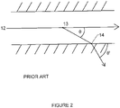
- Figure 2 shows details of the refractions within the bore of the prior art retained in the present invention. Shown therein is the geometry of incident light beam 12 scattered by the sample at the center of the cell 13 into the direction ⁇ and refracting at the air-glass interface 14 into the direction ⁇ '.
- the liquid solution passing therethrough is of refractive index n s and the glass is of refractive index n g with generally n s ⁇ n g .
- the light scattered at angle ⁇ within the liquid has been transformed into a refracted ray that will leave the bore at an angle ⁇ '. This was an important element of the prior art cell since the scattering at small scattering angles is transformed by refraction at the solution glass interface to larger scattering angles that are more experimentally accessible.
- ⁇ g will refer to the angle of the scattered light in the glass, after the Snell's law correction has been performed ( ⁇ ' according to US 4,616,927 A ). The final refractions at the cell's air-glass interfaces will be key items of importance.
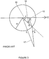
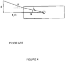
- FIG. 3 Another advantage of this cell geometry is that the cylindrical lens formed by the exterior of the cell focuses light along the beam that scatters at any scattering angle ⁇ s , indicated by the arcs 15 of Fig. 3 , with respect to the direction of the incident light beam 12 to a ring on which detectors may be placed at a distance f h from the center of the cell. Further details of the cell geometry of this prior art is shown in Fig. 3 .
- the beam acts as a line source along the horizontal axis. Let the radius of the cell be R, and let its index of refraction be n.
- a key element of the present invention means to provide more efficient capture of the light scattered by a sample within a flow cell by using a novel cylindrical lens to collect more light in the azimuthal direction (out of the scattering plane), while minimizing averaging in the axial direction (in the scattering plane).
- This is important because all multi-angle light scattering instruments measure the scattering intensity as a function of the axial angle ( ⁇ ) and averaging in this direction distorts the data and makes fitting to a model problematic. Averaging in the azimuthal direction is free from this problem.
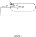
- the means by which the collection efficiency is increased is by modification of the prior art cell surface in its vertical direction to integrate the convex lens structure shown in Fig. 5 .
- ⁇ ⁇ l cos ⁇ + l sin ⁇ tan ⁇ ⁇ ⁇ g ⁇ ⁇ .
- Figure 6 shows a rendering of the inventive cell 18 and the major fittings required to maintain its position and function within a light scattering photometer.
- the cell is held by manifold means 19 and 20 and bottom plate 21 .
- a spring washer 22 insures contact of the cell with said manifolds.
- the axial bore 23 through the cell is connected with the manifolds so that liquids may flow unimpeded therethrough by O-rings seals 24 .
- Threaded bolts 25 , 26 , and 27 hold said cell manifolds and bottom plate 21 in a single assembly.
- a fine light beam may pass through said assembly by means of windows 28 sandwiched between O-ring seals 29 and threaded fittings 30 .
- Fluid solutions may flow through said sealed assembly containing connective passages through said manifolds into said bore by means of threaded fittings 31 permitting connection to chromatographic apparatus, pumps, sampling sources, etc.
- the optical windows could be incorporated into the cell structure itself by means, for example, of the fluid entrance and exit ports being machined directly into the cell and flattening the ends so as to permit the beam to enter and exit normal to the axial bore.
- a further advantage of the inventive method and apparatus relates to the ability of the new embodiments to simplify the elimination of significant amounts of stray light. Since the inventive flow cell described images the beam inside the flow cell to detectors lying on a ring at distance f therefrom, this results in a geometry particularly amenable to spatial filtering. In order to reject secondary scattered light from the edges of the flow cell bore, one need only put a slit 32 in front of each such detector 33 lying on said focal ring as shown in Fig. 7 . Shown thereon are two sets of scattered rays: those originate at the sample 34 that is illuminated at the center of the bore 35 and those that originate from stray light 36 at the bore-liquid interfaces 37 .
- One goal of the inventive design is to maximize the collection of scattered light from the cell.
- a small range of azimuthally scattered light is captured at each polar angle by the detector placed to receive it on the scattering ring previously described.
- the variation of scattered light intensity into a given polar direction as a function of azimuthal angle ⁇ is proportional to cos 2 ⁇ for particles whose size is very small relative to the wavelength of the incident light beam.
- the inventive design operates by imaging the line source of scattered light onto a ring lying on a common scattering plane in space by means of the novel cylindrical lens.
- Different lens elements associated with measurements of light scattered into different scattering planes with respect to a common bore 38 are shown at 39, 40 , and 41.
- a generalized structure forming a series of lenses covering the entire range of azimuthal angles is shown to the right at 42. Note, however, that the range of azimuthal angles focused to the corresponding scattering ring must be the same for each polar direction. Thus the range of the collection angle ⁇ is reduced as the polar angles approach 0° and 180°. Indeed, ⁇ ⁇ sin ⁇ .
Landscapes
- Physics & Mathematics (AREA)
- Health & Medical Sciences (AREA)
- Life Sciences & Earth Sciences (AREA)
- Chemical & Material Sciences (AREA)
- Analytical Chemistry (AREA)
- Biochemistry (AREA)
- General Health & Medical Sciences (AREA)
- General Physics & Mathematics (AREA)
- Immunology (AREA)
- Pathology (AREA)
- Optical Measuring Cells (AREA)
- Investigating Or Analysing Materials By Optical Means (AREA)
Applications Claiming Priority (1)
| Application Number | Priority Date | Filing Date | Title |
|---|---|---|---|
| US12/456,470 US7982875B2 (en) | 2009-06-15 | 2009-06-15 | Method and apparatus for measuring the scattered light signals from a liquid sample |
Publications (2)
| Publication Number | Publication Date |
|---|---|
| EP2264437A1 EP2264437A1 (en) | 2010-12-22 |
| EP2264437B1 true EP2264437B1 (en) | 2022-08-24 |
Family
ID=42734803
Family Applications (1)
| Application Number | Title | Priority Date | Filing Date |
|---|---|---|---|
| EP10166074.4A Active EP2264437B1 (en) | 2009-06-15 | 2010-06-15 | Improved apparatus for measuring the scattered light signals from a liquid sample |
Country Status (4)
| Country | Link |
|---|---|
| US (1) | US7982875B2 (enExample) |
| EP (1) | EP2264437B1 (enExample) |
| JP (2) | JP5859187B2 (enExample) |
| CN (1) | CN101963579B (enExample) |
Families Citing this family (17)
| Publication number | Priority date | Publication date | Assignee | Title |
|---|---|---|---|---|
| EP2584353B1 (de) * | 2011-10-18 | 2018-01-24 | Postnova Analytics GmbH | Blendensystem für Vielwinkellichtstreudetektoren |
| DE202014102634U1 (de) | 2014-06-05 | 2014-07-01 | Postnova Analytics Gmbh | Zweiteilige Messzelle für die statische Lichtstreuung |
| CN105527224B (zh) * | 2014-09-29 | 2019-02-22 | 安东帕有限公司 | 一种用于分析样品的设备和方法 |
| WO2017053478A1 (en) | 2015-09-22 | 2017-03-30 | Wyatt Technology Corporation | Method and apparatus to measure multiple signals from a liquid sample |
| EP3420338B1 (en) * | 2016-02-26 | 2023-05-03 | Single Technologies AB | Method and apparatus for high throughput imaging |
| WO2018054852A1 (en) * | 2016-09-22 | 2018-03-29 | Imec Vzw | Particle detection using thin lenses |
| US20180156717A1 (en) * | 2016-12-05 | 2018-06-07 | Bill & Melinda Gates Foundation | Multi-test assay systems and methods of using the same |
| US20190383726A1 (en) * | 2016-12-27 | 2019-12-19 | National Institute Of Advanced Industrial Science And Technology | Flow cell for optical measurement |
| US10466173B2 (en) | 2017-10-06 | 2019-11-05 | Wyatt Technology Corporation | Optical flow cell assembly incorporating a replaceable transparent flow cell |
| JP7140193B2 (ja) * | 2018-08-01 | 2022-09-21 | 株式会社島津製作所 | 光散乱検出装置 |
| JP7187874B2 (ja) * | 2018-08-02 | 2022-12-13 | 株式会社島津製作所 | 光散乱検出装置 |
| CN108760686B (zh) * | 2018-08-07 | 2024-05-14 | 天津诺迈科技有限公司 | 散射比浊法检测微流控芯片及使用该芯片的生化免疫机 |
| WO2020142096A1 (en) | 2019-01-02 | 2020-07-09 | M & J Scientific, Llc | Light scattering detectors and methods for the same |
| JP7307495B2 (ja) | 2019-01-02 | 2023-07-12 | エム アンド ジェイ サイエンティフィック エルエルシー | 光散乱検出器及び光散乱検出器のサンプルセル |
| CN109932450B (zh) * | 2019-04-03 | 2022-01-25 | 安徽皖仪科技股份有限公司 | 流通池和具有其的液相色谱仪 |
| US11733144B2 (en) * | 2020-12-14 | 2023-08-22 | Caterpillar Inc. | Convertible housing assembly for a particle sensor |
| US11555776B2 (en) | 2021-02-03 | 2023-01-17 | Shimadzu Corporation | Light scattering detection apparatus |
Family Cites Families (35)
| Publication number | Priority date | Publication date | Assignee | Title |
|---|---|---|---|---|
| US3705771A (en) * | 1970-01-14 | 1972-12-12 | Bio Physics Systems Inc | Photoanalysis apparatus |
| US4490042A (en) * | 1981-06-04 | 1984-12-25 | Wyatt Philip J | Method for determining the properties of wine |
| JPS57208439A (en) * | 1981-06-18 | 1982-12-21 | Olympus Optical Co Ltd | Particle coagulation discriminating vessel |
| US4541719A (en) * | 1982-07-20 | 1985-09-17 | Wyatt Philip J | Method and apparatus for characterizing microparticles and measuring their response to their environment |
| US4565448A (en) * | 1983-03-11 | 1986-01-21 | E. I. Du Pont De Nemours And Company | Particle counting apparatus |
| JPS60161548A (ja) * | 1984-01-31 | 1985-08-23 | Canon Inc | 流動微小粒子状物体の散乱光測定装置 |
| FR2566543B1 (fr) * | 1984-06-20 | 1988-02-26 | Commissariat Energie Atomique | Dispositif optique a rendement de collection eleve et cytofluorimetre en faisant application |
| US4907884A (en) | 1984-11-15 | 1990-03-13 | Wyatt Technology Corporation | Sample cell monitoring system |
| US4616927A (en) * | 1984-11-15 | 1986-10-14 | Wyatt Technology Corporation | Sample cell for light scattering measurements |
| US4591268A (en) * | 1984-11-23 | 1986-05-27 | Lew Hyok S | Accumulative absorption-dispersion spectrophotometer |
| US4952055A (en) | 1988-10-03 | 1990-08-28 | Wyatt Technology Corporation | Differential refractometer |
| USD329821S (en) | 1989-02-21 | 1992-09-29 | Wyatt Technology Corporation | Apparatus for the measurement of fine particles in liquid suspension by the light scattering procedure |
| US5175596A (en) * | 1990-10-23 | 1992-12-29 | Venturedyne, Ltd. | Liquid nephelometer |
| US5495333A (en) * | 1992-07-24 | 1996-02-27 | Sumitomo Electric Industries, Ltd. | Method and apparatus of detecting impurities in fluid |
| US5404217A (en) * | 1993-08-26 | 1995-04-04 | Janik; Gary R. | Laser liquid flow cell manifold system and method for assembly |
| US5530540A (en) | 1994-08-03 | 1996-06-25 | Wyatt Technology Corporation | Light scattering measurement cell for very small volumes |
| JP3124989B2 (ja) * | 1994-12-19 | 2001-01-15 | リオン株式会社 | 光散乱式粒子検出装置 |
| US5734468A (en) * | 1995-08-18 | 1998-03-31 | Beckman Instruments, Inc. | Probe and method for determining serum indices of a serum sample |
| JP3567949B2 (ja) * | 1995-10-24 | 2004-09-22 | 石川島播磨重工業株式会社 | レーザレーダ装置 |
| US6052184A (en) * | 1996-11-13 | 2000-04-18 | The Administrators Of The Tulane Educational Fund | Miniature, submersible, versatile, light scattering probe for absolute equilibrium and non-equilibrium characterization of macromolecular and colloidal solutions |
| US20040004717A1 (en) * | 1996-11-13 | 2004-01-08 | Reed Wayne F. | Automatic mixing and dilution methods and apparatus for online characterization of equilibrium and non-equilibrium properties of solutions containing polymers and/or colloids |
| US6452672B1 (en) * | 2000-03-10 | 2002-09-17 | Wyatt Technology Corporation | Self cleaning optical flow cell |
| JP4439765B2 (ja) * | 2001-07-23 | 2010-03-24 | 株式会社堀場製作所 | 粒子径分布測定装置 |
| US6590652B2 (en) * | 2001-11-02 | 2003-07-08 | Pointsource Technologies, Inc. | Flow through light scattering device |
| US7057724B1 (en) * | 2002-03-21 | 2006-06-06 | Institute Of Critical Care Medicine | Particulate info to field units |
| US6651009B1 (en) | 2002-07-24 | 2003-11-18 | Wyatt Technology Corporation | Method for determining average solution properties of macromolecules by the injection method |
| GB2403815A (en) * | 2003-07-10 | 2005-01-12 | Ocuity Ltd | Birefringent lens array structure |
| US6774994B1 (en) | 2003-08-13 | 2004-08-10 | Wyatt Technology Corporation | Method and apparatus for determining absolute number densities of particles in suspension |
| DE10341520A1 (de) * | 2003-09-09 | 2005-04-07 | Schupp, Wolfgang, Dr. | Verfahren und Vorrichtung zur Durchführung einer Lichtstreuung |
| US7386427B2 (en) | 2003-09-18 | 2008-06-10 | Wyatt Technology Corporation | Method for correcting the effects of interdetector band broadening |
| US7151604B2 (en) * | 2004-03-05 | 2006-12-19 | Honeywell International Inc. | Optical system and method for particle detection |
| JP2006066736A (ja) | 2004-08-27 | 2006-03-09 | Orion Denki Kk | コード結束用フックを備えた液晶型テレビ |
| US7113266B1 (en) * | 2005-03-30 | 2006-09-26 | Beckman Coulter, Inc. | Flow cytometer for differentiating small particles in suspension |
| JP2008039539A (ja) * | 2006-08-04 | 2008-02-21 | Shimadzu Corp | 光散乱検出装置 |
| WO2010036736A2 (en) * | 2008-09-25 | 2010-04-01 | Varian, Inc | Light scattering flow cell device |
-
2009
- 2009-06-15 US US12/456,470 patent/US7982875B2/en active Active
-
2010
- 2010-06-13 CN CN201010205250.0A patent/CN101963579B/zh active Active
- 2010-06-14 JP JP2010135191A patent/JP5859187B2/ja active Active
- 2010-06-15 EP EP10166074.4A patent/EP2264437B1/en active Active
-
2015
- 2015-03-18 JP JP2015054737A patent/JP5886994B2/ja active Active
Also Published As
| Publication number | Publication date |
|---|---|
| CN101963579B (zh) | 2016-01-20 |
| JP2010286491A (ja) | 2010-12-24 |
| US7982875B2 (en) | 2011-07-19 |
| JP2015111163A (ja) | 2015-06-18 |
| US20100315637A1 (en) | 2010-12-16 |
| JP5859187B2 (ja) | 2016-02-10 |
| JP5886994B2 (ja) | 2016-03-16 |
| CN101963579A (zh) | 2011-02-02 |
| EP2264437A1 (en) | 2010-12-22 |
Similar Documents
| Publication | Publication Date | Title |
|---|---|---|
| EP2264437B1 (en) | Improved apparatus for measuring the scattered light signals from a liquid sample | |
| US5430541A (en) | High efficiency fluorescence flow cell for capillary liquid chromatography or capillary electrophoresis | |
| US4088407A (en) | High pressure fluorescence flow-through cuvette | |
| EP0182618B1 (en) | Sample cell for light scattering measurements | |
| US5127729A (en) | Method and apparatus for guiding and collecting light in photometry or the like | |
| US4348107A (en) | Orifice inside optical element | |
| US5292483A (en) | Detecting a radiation signal | |
| US12493181B2 (en) | Optical spectroscopy probe configurations for focusing light to a portion of a sample | |
| EP3066452B1 (en) | Improvements relating to particle characterisation | |
| US10126229B2 (en) | Optical measurement device | |
| EP0389571A1 (en) | DIFFERENTIAL REFRACTOMETER. | |
| JPH07503796A (ja) | 分子特性解析の方法及び装置 | |
| JP2010286491A5 (enExample) | ||
| CN1758052B (zh) | 结合有光检测器阵列的灵敏度增强的差示折射计 | |
| WO2012137750A1 (ja) | 長光路長フローセル | |
| EP2869054A1 (en) | Improvements relating to particle characterisation | |
| GB2125181A (en) | Flow cells for particle study | |
| EP2869057A1 (en) | Improvements Relating to Particle Characterisation | |
| CN212059104U (zh) | 一种宽光谱高灵敏度拉曼光谱仪 | |
| EP2869056A1 (en) | Improvements relating to particle characterisation | |
| JPH09503064A (ja) | 液体中の物質を検出する新規な方法 | |
| CN212059105U (zh) | 一种高分辨率高灵敏度拉曼光谱仪 | |
| RU2182329C2 (ru) | Флуориметрический детектор | |
| EP2869055A1 (en) | Improvements relating to particle characterisation | |
| RU2008669C1 (ru) | Флуориметрический детектор жидкостного хроматографа |
Legal Events
| Date | Code | Title | Description |
|---|---|---|---|
| PUAI | Public reference made under article 153(3) epc to a published international application that has entered the european phase |
Free format text: ORIGINAL CODE: 0009012 |
|
| AK | Designated contracting states |
Kind code of ref document: A1 Designated state(s): AL AT BE BG CH CY CZ DE DK EE ES FI FR GB GR HR HU IE IS IT LI LT LU LV MC MK MT NL NO PL PT RO SE SI SK SM TR |
|
| AX | Request for extension of the european patent |
Extension state: BA ME RS |
|
| 17P | Request for examination filed |
Effective date: 20110622 |
|
| STAA | Information on the status of an ep patent application or granted ep patent |
Free format text: STATUS: EXAMINATION IS IN PROGRESS |
|
| 17Q | First examination report despatched |
Effective date: 20180620 |
|
| GRAP | Despatch of communication of intention to grant a patent |
Free format text: ORIGINAL CODE: EPIDOSNIGR1 |
|
| STAA | Information on the status of an ep patent application or granted ep patent |
Free format text: STATUS: GRANT OF PATENT IS INTENDED |
|
| RIC1 | Information provided on ipc code assigned before grant |
Ipc: G01N 21/47 20060101ALI20220217BHEP Ipc: G01N 21/03 20060101ALI20220217BHEP Ipc: G01N 21/05 20060101ALI20220217BHEP Ipc: G01N 21/51 20060101AFI20220217BHEP |
|
| INTG | Intention to grant announced |
Effective date: 20220311 |
|
| GRAS | Grant fee paid |
Free format text: ORIGINAL CODE: EPIDOSNIGR3 |
|
| GRAA | (expected) grant |
Free format text: ORIGINAL CODE: 0009210 |
|
| STAA | Information on the status of an ep patent application or granted ep patent |
Free format text: STATUS: THE PATENT HAS BEEN GRANTED |
|
| AK | Designated contracting states |
Kind code of ref document: B1 Designated state(s): AL AT BE BG CH CY CZ DE DK EE ES FI FR GB GR HR HU IE IS IT LI LT LU LV MC MK MT NL NO PL PT RO SE SI SK SM TR |
|
| REG | Reference to a national code |
Ref country code: GB Ref legal event code: FG4D |
|
| REG | Reference to a national code |
Ref country code: CH Ref legal event code: EP |
|
| REG | Reference to a national code |
Ref country code: IE Ref legal event code: FG4D |
|
| REG | Reference to a national code |
Ref country code: AT Ref legal event code: REF Ref document number: 1513983 Country of ref document: AT Kind code of ref document: T Effective date: 20220915 Ref country code: DE Ref legal event code: R096 Ref document number: 602010068435 Country of ref document: DE |
|
| REG | Reference to a national code |
Ref country code: LT Ref legal event code: MG9D |
|
| REG | Reference to a national code |
Ref country code: NL Ref legal event code: MP Effective date: 20220824 |
|
| PG25 | Lapsed in a contracting state [announced via postgrant information from national office to epo] |
Ref country code: SE Free format text: LAPSE BECAUSE OF FAILURE TO SUBMIT A TRANSLATION OF THE DESCRIPTION OR TO PAY THE FEE WITHIN THE PRESCRIBED TIME-LIMIT Effective date: 20220824 Ref country code: PT Free format text: LAPSE BECAUSE OF FAILURE TO SUBMIT A TRANSLATION OF THE DESCRIPTION OR TO PAY THE FEE WITHIN THE PRESCRIBED TIME-LIMIT Effective date: 20221226 Ref country code: NO Free format text: LAPSE BECAUSE OF FAILURE TO SUBMIT A TRANSLATION OF THE DESCRIPTION OR TO PAY THE FEE WITHIN THE PRESCRIBED TIME-LIMIT Effective date: 20221124 Ref country code: NL Free format text: LAPSE BECAUSE OF FAILURE TO SUBMIT A TRANSLATION OF THE DESCRIPTION OR TO PAY THE FEE WITHIN THE PRESCRIBED TIME-LIMIT Effective date: 20220824 Ref country code: LV Free format text: LAPSE BECAUSE OF FAILURE TO SUBMIT A TRANSLATION OF THE DESCRIPTION OR TO PAY THE FEE WITHIN THE PRESCRIBED TIME-LIMIT Effective date: 20220824 Ref country code: LT Free format text: LAPSE BECAUSE OF FAILURE TO SUBMIT A TRANSLATION OF THE DESCRIPTION OR TO PAY THE FEE WITHIN THE PRESCRIBED TIME-LIMIT Effective date: 20220824 Ref country code: FI Free format text: LAPSE BECAUSE OF FAILURE TO SUBMIT A TRANSLATION OF THE DESCRIPTION OR TO PAY THE FEE WITHIN THE PRESCRIBED TIME-LIMIT Effective date: 20220824 Ref country code: ES Free format text: LAPSE BECAUSE OF FAILURE TO SUBMIT A TRANSLATION OF THE DESCRIPTION OR TO PAY THE FEE WITHIN THE PRESCRIBED TIME-LIMIT Effective date: 20220824 |
|
| REG | Reference to a national code |
Ref country code: AT Ref legal event code: MK05 Ref document number: 1513983 Country of ref document: AT Kind code of ref document: T Effective date: 20220824 |
|
| PG25 | Lapsed in a contracting state [announced via postgrant information from national office to epo] |
Ref country code: PL Free format text: LAPSE BECAUSE OF FAILURE TO SUBMIT A TRANSLATION OF THE DESCRIPTION OR TO PAY THE FEE WITHIN THE PRESCRIBED TIME-LIMIT Effective date: 20220824 Ref country code: IS Free format text: LAPSE BECAUSE OF FAILURE TO SUBMIT A TRANSLATION OF THE DESCRIPTION OR TO PAY THE FEE WITHIN THE PRESCRIBED TIME-LIMIT Effective date: 20221224 Ref country code: HR Free format text: LAPSE BECAUSE OF FAILURE TO SUBMIT A TRANSLATION OF THE DESCRIPTION OR TO PAY THE FEE WITHIN THE PRESCRIBED TIME-LIMIT Effective date: 20220824 Ref country code: GR Free format text: LAPSE BECAUSE OF FAILURE TO SUBMIT A TRANSLATION OF THE DESCRIPTION OR TO PAY THE FEE WITHIN THE PRESCRIBED TIME-LIMIT Effective date: 20221125 |
|
| PG25 | Lapsed in a contracting state [announced via postgrant information from national office to epo] |
Ref country code: SM Free format text: LAPSE BECAUSE OF FAILURE TO SUBMIT A TRANSLATION OF THE DESCRIPTION OR TO PAY THE FEE WITHIN THE PRESCRIBED TIME-LIMIT Effective date: 20220824 Ref country code: RO Free format text: LAPSE BECAUSE OF FAILURE TO SUBMIT A TRANSLATION OF THE DESCRIPTION OR TO PAY THE FEE WITHIN THE PRESCRIBED TIME-LIMIT Effective date: 20220824 Ref country code: DK Free format text: LAPSE BECAUSE OF FAILURE TO SUBMIT A TRANSLATION OF THE DESCRIPTION OR TO PAY THE FEE WITHIN THE PRESCRIBED TIME-LIMIT Effective date: 20220824 Ref country code: CZ Free format text: LAPSE BECAUSE OF FAILURE TO SUBMIT A TRANSLATION OF THE DESCRIPTION OR TO PAY THE FEE WITHIN THE PRESCRIBED TIME-LIMIT Effective date: 20220824 Ref country code: AT Free format text: LAPSE BECAUSE OF FAILURE TO SUBMIT A TRANSLATION OF THE DESCRIPTION OR TO PAY THE FEE WITHIN THE PRESCRIBED TIME-LIMIT Effective date: 20220824 |
|
| REG | Reference to a national code |
Ref country code: DE Ref legal event code: R097 Ref document number: 602010068435 Country of ref document: DE |
|
| PG25 | Lapsed in a contracting state [announced via postgrant information from national office to epo] |
Ref country code: SK Free format text: LAPSE BECAUSE OF FAILURE TO SUBMIT A TRANSLATION OF THE DESCRIPTION OR TO PAY THE FEE WITHIN THE PRESCRIBED TIME-LIMIT Effective date: 20220824 Ref country code: EE Free format text: LAPSE BECAUSE OF FAILURE TO SUBMIT A TRANSLATION OF THE DESCRIPTION OR TO PAY THE FEE WITHIN THE PRESCRIBED TIME-LIMIT Effective date: 20220824 |
|
| PG25 | Lapsed in a contracting state [announced via postgrant information from national office to epo] |
Ref country code: AL Free format text: LAPSE BECAUSE OF FAILURE TO SUBMIT A TRANSLATION OF THE DESCRIPTION OR TO PAY THE FEE WITHIN THE PRESCRIBED TIME-LIMIT Effective date: 20220824 |
|
| PLBE | No opposition filed within time limit |
Free format text: ORIGINAL CODE: 0009261 |
|
| STAA | Information on the status of an ep patent application or granted ep patent |
Free format text: STATUS: NO OPPOSITION FILED WITHIN TIME LIMIT |
|
| P01 | Opt-out of the competence of the unified patent court (upc) registered |
Effective date: 20230526 |
|
| 26N | No opposition filed |
Effective date: 20230525 |
|
| PG25 | Lapsed in a contracting state [announced via postgrant information from national office to epo] |
Ref country code: SI Free format text: LAPSE BECAUSE OF FAILURE TO SUBMIT A TRANSLATION OF THE DESCRIPTION OR TO PAY THE FEE WITHIN THE PRESCRIBED TIME-LIMIT Effective date: 20220824 |
|
| PG25 | Lapsed in a contracting state [announced via postgrant information from national office to epo] |
Ref country code: MC Free format text: LAPSE BECAUSE OF FAILURE TO SUBMIT A TRANSLATION OF THE DESCRIPTION OR TO PAY THE FEE WITHIN THE PRESCRIBED TIME-LIMIT Effective date: 20220824 |
|
| PG25 | Lapsed in a contracting state [announced via postgrant information from national office to epo] |
Ref country code: MC Free format text: LAPSE BECAUSE OF FAILURE TO SUBMIT A TRANSLATION OF THE DESCRIPTION OR TO PAY THE FEE WITHIN THE PRESCRIBED TIME-LIMIT Effective date: 20220824 |
|
| REG | Reference to a national code |
Ref country code: CH Ref legal event code: PL |
|
| REG | Reference to a national code |
Ref country code: BE Ref legal event code: MM Effective date: 20230630 |
|
| PG25 | Lapsed in a contracting state [announced via postgrant information from national office to epo] |
Ref country code: LU Free format text: LAPSE BECAUSE OF NON-PAYMENT OF DUE FEES Effective date: 20230615 |
|
| REG | Reference to a national code |
Ref country code: IE Ref legal event code: MM4A |
|
| PG25 | Lapsed in a contracting state [announced via postgrant information from national office to epo] |
Ref country code: LU Free format text: LAPSE BECAUSE OF NON-PAYMENT OF DUE FEES Effective date: 20230615 |
|
| PG25 | Lapsed in a contracting state [announced via postgrant information from national office to epo] |
Ref country code: IE Free format text: LAPSE BECAUSE OF NON-PAYMENT OF DUE FEES Effective date: 20230615 |
|
| PG25 | Lapsed in a contracting state [announced via postgrant information from national office to epo] |
Ref country code: IE Free format text: LAPSE BECAUSE OF NON-PAYMENT OF DUE FEES Effective date: 20230615 Ref country code: CH Free format text: LAPSE BECAUSE OF NON-PAYMENT OF DUE FEES Effective date: 20230630 |
|
| PG25 | Lapsed in a contracting state [announced via postgrant information from national office to epo] |
Ref country code: IT Free format text: LAPSE BECAUSE OF FAILURE TO SUBMIT A TRANSLATION OF THE DESCRIPTION OR TO PAY THE FEE WITHIN THE PRESCRIBED TIME-LIMIT Effective date: 20220824 Ref country code: FR Free format text: LAPSE BECAUSE OF NON-PAYMENT OF DUE FEES Effective date: 20230630 Ref country code: BE Free format text: LAPSE BECAUSE OF NON-PAYMENT OF DUE FEES Effective date: 20230630 |
|
| PG25 | Lapsed in a contracting state [announced via postgrant information from national office to epo] |
Ref country code: BG Free format text: LAPSE BECAUSE OF FAILURE TO SUBMIT A TRANSLATION OF THE DESCRIPTION OR TO PAY THE FEE WITHIN THE PRESCRIBED TIME-LIMIT Effective date: 20220824 |
|
| PG25 | Lapsed in a contracting state [announced via postgrant information from national office to epo] |
Ref country code: BG Free format text: LAPSE BECAUSE OF FAILURE TO SUBMIT A TRANSLATION OF THE DESCRIPTION OR TO PAY THE FEE WITHIN THE PRESCRIBED TIME-LIMIT Effective date: 20220824 |
|
| PGFP | Annual fee paid to national office [announced via postgrant information from national office to epo] |
Ref country code: DE Payment date: 20250520 Year of fee payment: 16 |
|
| PGFP | Annual fee paid to national office [announced via postgrant information from national office to epo] |
Ref country code: GB Payment date: 20250520 Year of fee payment: 16 |
|
| PG25 | Lapsed in a contracting state [announced via postgrant information from national office to epo] |
Ref country code: CY Free format text: LAPSE BECAUSE OF FAILURE TO SUBMIT A TRANSLATION OF THE DESCRIPTION OR TO PAY THE FEE WITHIN THE PRESCRIBED TIME-LIMIT; INVALID AB INITIO Effective date: 20100615 |
|
| PG25 | Lapsed in a contracting state [announced via postgrant information from national office to epo] |
Ref country code: HU Free format text: LAPSE BECAUSE OF FAILURE TO SUBMIT A TRANSLATION OF THE DESCRIPTION OR TO PAY THE FEE WITHIN THE PRESCRIBED TIME-LIMIT; INVALID AB INITIO Effective date: 20100615 |
|
| PG25 | Lapsed in a contracting state [announced via postgrant information from national office to epo] |
Ref country code: TR Free format text: LAPSE BECAUSE OF FAILURE TO SUBMIT A TRANSLATION OF THE DESCRIPTION OR TO PAY THE FEE WITHIN THE PRESCRIBED TIME-LIMIT Effective date: 20220824 |