EP2264334B1 - Hybridgetriebe und Betriebsverfahren eines solchen Getriebes - Google Patents
Hybridgetriebe und Betriebsverfahren eines solchen Getriebes Download PDFInfo
- Publication number
- EP2264334B1 EP2264334B1 EP10165868.0A EP10165868A EP2264334B1 EP 2264334 B1 EP2264334 B1 EP 2264334B1 EP 10165868 A EP10165868 A EP 10165868A EP 2264334 B1 EP2264334 B1 EP 2264334B1
- Authority
- EP
- European Patent Office
- Prior art keywords
- drive
- transmission
- gear
- input member
- power
- Prior art date
- Legal status (The legal status is an assumption and is not a legal conclusion. Google has not performed a legal analysis and makes no representation as to the accuracy of the status listed.)
- Active
Links
Images

Classifications
-
- B—PERFORMING OPERATIONS; TRANSPORTING
- B60—VEHICLES IN GENERAL
- B60K—ARRANGEMENT OR MOUNTING OF PROPULSION UNITS OR OF TRANSMISSIONS IN VEHICLES; ARRANGEMENT OR MOUNTING OF PLURAL DIVERSE PRIME-MOVERS IN VEHICLES; AUXILIARY DRIVES FOR VEHICLES; INSTRUMENTATION OR DASHBOARDS FOR VEHICLES; ARRANGEMENTS IN CONNECTION WITH COOLING, AIR INTAKE, GAS EXHAUST OR FUEL SUPPLY OF PROPULSION UNITS IN VEHICLES
- B60K17/00—Arrangement or mounting of transmissions in vehicles
- B60K17/34—Arrangement or mounting of transmissions in vehicles for driving both front and rear wheels, e.g. four wheel drive vehicles
- B60K17/348—Arrangement or mounting of transmissions in vehicles for driving both front and rear wheels, e.g. four wheel drive vehicles having differential means for driving one set of wheels, e.g. the front, at one speed and the other set, e.g. the rear, at a different speed
- B60K17/35—Arrangement or mounting of transmissions in vehicles for driving both front and rear wheels, e.g. four wheel drive vehicles having differential means for driving one set of wheels, e.g. the front, at one speed and the other set, e.g. the rear, at a different speed including arrangements for suppressing or influencing the power transfer, e.g. viscous clutches
-
- B—PERFORMING OPERATIONS; TRANSPORTING
- B60—VEHICLES IN GENERAL
- B60K—ARRANGEMENT OR MOUNTING OF PROPULSION UNITS OR OF TRANSMISSIONS IN VEHICLES; ARRANGEMENT OR MOUNTING OF PLURAL DIVERSE PRIME-MOVERS IN VEHICLES; AUXILIARY DRIVES FOR VEHICLES; INSTRUMENTATION OR DASHBOARDS FOR VEHICLES; ARRANGEMENTS IN CONNECTION WITH COOLING, AIR INTAKE, GAS EXHAUST OR FUEL SUPPLY OF PROPULSION UNITS IN VEHICLES
- B60K23/00—Arrangement or mounting of control devices for vehicle transmissions, or parts thereof, not otherwise provided for
- B60K23/08—Arrangement or mounting of control devices for vehicle transmissions, or parts thereof, not otherwise provided for for changing number of driven wheels, for switching from driving one axle to driving two or more axles
-
- B—PERFORMING OPERATIONS; TRANSPORTING
- B60—VEHICLES IN GENERAL
- B60K—ARRANGEMENT OR MOUNTING OF PROPULSION UNITS OR OF TRANSMISSIONS IN VEHICLES; ARRANGEMENT OR MOUNTING OF PLURAL DIVERSE PRIME-MOVERS IN VEHICLES; AUXILIARY DRIVES FOR VEHICLES; INSTRUMENTATION OR DASHBOARDS FOR VEHICLES; ARRANGEMENTS IN CONNECTION WITH COOLING, AIR INTAKE, GAS EXHAUST OR FUEL SUPPLY OF PROPULSION UNITS IN VEHICLES
- B60K23/00—Arrangement or mounting of control devices for vehicle transmissions, or parts thereof, not otherwise provided for
- B60K23/08—Arrangement or mounting of control devices for vehicle transmissions, or parts thereof, not otherwise provided for for changing number of driven wheels, for switching from driving one axle to driving two or more axles
- B60K23/0808—Arrangement or mounting of control devices for vehicle transmissions, or parts thereof, not otherwise provided for for changing number of driven wheels, for switching from driving one axle to driving two or more axles for varying torque distribution between driven axles, e.g. by transfer clutch
-
- F—MECHANICAL ENGINEERING; LIGHTING; HEATING; WEAPONS; BLASTING
- F16—ENGINEERING ELEMENTS AND UNITS; GENERAL MEASURES FOR PRODUCING AND MAINTAINING EFFECTIVE FUNCTIONING OF MACHINES OR INSTALLATIONS; THERMAL INSULATION IN GENERAL
- F16H—GEARING
- F16H47/00—Combinations of mechanical gearing with fluid clutches or fluid gearing
- F16H47/02—Combinations of mechanical gearing with fluid clutches or fluid gearing the fluid gearing being of the volumetric type
-
- F—MECHANICAL ENGINEERING; LIGHTING; HEATING; WEAPONS; BLASTING
- F16—ENGINEERING ELEMENTS AND UNITS; GENERAL MEASURES FOR PRODUCING AND MAINTAINING EFFECTIVE FUNCTIONING OF MACHINES OR INSTALLATIONS; THERMAL INSULATION IN GENERAL
- F16H—GEARING
- F16H3/00—Toothed gearings for conveying rotary motion with variable gear ratio or for reversing rotary motion
- F16H3/02—Toothed gearings for conveying rotary motion with variable gear ratio or for reversing rotary motion without gears having orbital motion
- F16H3/08—Toothed gearings for conveying rotary motion with variable gear ratio or for reversing rotary motion without gears having orbital motion exclusively or essentially with continuously meshing gears, that can be disengaged from their shafts
- F16H2003/0818—Toothed gearings for conveying rotary motion with variable gear ratio or for reversing rotary motion without gears having orbital motion exclusively or essentially with continuously meshing gears, that can be disengaged from their shafts comprising means for power-shifting
-
- Y—GENERAL TAGGING OF NEW TECHNOLOGICAL DEVELOPMENTS; GENERAL TAGGING OF CROSS-SECTIONAL TECHNOLOGIES SPANNING OVER SEVERAL SECTIONS OF THE IPC; TECHNICAL SUBJECTS COVERED BY FORMER USPC CROSS-REFERENCE ART COLLECTIONS [XRACs] AND DIGESTS
- Y10—TECHNICAL SUBJECTS COVERED BY FORMER USPC
- Y10T—TECHNICAL SUBJECTS COVERED BY FORMER US CLASSIFICATION
- Y10T74/00—Machine element or mechanism
- Y10T74/19—Gearing
- Y10T74/19023—Plural power paths to and/or from gearing
-
- Y—GENERAL TAGGING OF NEW TECHNOLOGICAL DEVELOPMENTS; GENERAL TAGGING OF CROSS-SECTIONAL TECHNOLOGIES SPANNING OVER SEVERAL SECTIONS OF THE IPC; TECHNICAL SUBJECTS COVERED BY FORMER USPC CROSS-REFERENCE ART COLLECTIONS [XRACs] AND DIGESTS
- Y10—TECHNICAL SUBJECTS COVERED BY FORMER USPC
- Y10T—TECHNICAL SUBJECTS COVERED BY FORMER US CLASSIFICATION
- Y10T74/00—Machine element or mechanism
- Y10T74/19—Gearing
- Y10T74/19023—Plural power paths to and/or from gearing
- Y10T74/19051—Single driven plural drives
Definitions
- This invention relates to a transmission and more particularly to a hybrid transmission for a vehicle, by means of which drive may be transmitted via a mechanical drive train to a ground engaging structure of the vehicle to drive the vehicle, or drive may be transmitted by the operation of a hydraulic motor.
- US4242922 also discloses a hybrid transmission, with a mechanical drive train being established through permanently meshing gears upon the selective engagement of a clutch.
- the hydrostatic drive train again is not distinct from the gear ratio selection apparatus, but is via a drive shaft which passes though the selectable (disengaged) clutches of the gear ratio selection apparatus.
- gear ratio selection apparatus at least of the mechanical drive train and components of the drive established by the operation of the hydraulic motor to be distinct, so that for example existing successful gear ratio selection apparatus may readily be used as part of a hybrid transmission.
- DE102006038093 teaches a transmission in which a mechanical drive train incorporating a gear ratio selection apparatus, is distinct from a hydrostatic drive from a hydraulic motor.
- a vehicle with such a transmission may be driven in mechanical drive mode for example on the highway, or during working operations where slow, closely controlled speeds are required, in hydrostatic drive mode.
- JP6300113 , JP2006/248341 , US2002/139597 , DE3733883 and DE 10 2006 018435 show alternative transmission arrangements.
- US 2002/139597 discloses a transmission according to the preamble of claim 1 and constitutes the closest prior art to the subject-matter of claim 10.
- the apparatus of the invention provides an improved hybrid transmission in which at low speeds when maximum control is required for manoeuvres, e.g. where the vehicle is a working machine, during working operations, drive to the ground engaging drive structure is effected by operation of the hydraulic drive motor, whilst at higher speeds, e.g. in the case of a working machine, at road speeds, drive may be effected via the mechanical drive train, with a selected gear ratio.
- the transmission may be changed between mechanical and hydrostatic drive modes whilst the vehicle is travelling, for example at a threshold speed.
- power-shift clutch devices we mean devices which include an actuator to move input and output parts into and out of frictional engagement to transmit or interrupt drive respectively. It will be appreciated that friction material is usually employed which permits slippage between the input and output parts when in a transition state between being fully frictionally engaged and fully disengaged. Thus drive may be continuously transmitted during change over between mechanical and hydrostatic drive modes, by simultaneously engaging and disengaging the various power-shift clutch devices though their transition states.
- the operation of the transmission may be controlled by a controller.
- the controller may operate the power-shift clutch devices of the mechanical drive train to select a gear ratio, for example automatically depending on vehicle speed, and load, and/or the controller may operate the power-shift clutch devices of the mechanical drive train to select a gear ratio in response to an input from an operator.
- the controller may operate the power-shift clutch devices of the mechanical drive train and the power-shift clutch device between the hydraulic drive motor and the second input member, to change between mechanical and hydrostatic drive modes in response to the vehicle being determined to be travelling at a threshold speed and depending upon whether the vehicle is accelerating or decelerating.
- the pump preferably is permanently connected to the prime mover i.e. the pump is driven regardless of whether drive is transmitted though the mechanical gear train or is established by the operation of the hydraulic drive motor.
- the hydraulic pump may be permanently connected to the first input member e.g. by permanently meshing transmission gears.
- the output member of the transmission may be connected to wheels and/or tracks of the ground engaging drive structure, directly or via one or more further transmission component as required.
- a transmission 10 is provided for transmitting drive to a ground engaging driven structure 12 which may be wheels and/or tracks of a vehicle.
- the vehicle is a working machine which is driven from location to location on the ground engaging driven structure 12, and which may perform working operations such as lifting, loading and moving earth, agricultural and other materials at such location.
- the vehicle includes a prime mover 13, typically a diesel engine, whose output drive shaft is connected to (or integral with) a first input member 15 of the transmission 10.
- the first input member is a first drive shaft 15 of the transmission 10.
- the first drive shaft 15 carries a drive take-off gear 16 which is fast with and rotates with the shaft 15, the drive take-off gear 16 being in permanent mesh with a driven gear 17 which is fast with a hydraulic pump 18 input shaft 19.
- the hydraulic pump 18 will be driven whenever the prime mover 13 rotates the first input member 15 i.e. whenever the engine 13 is running.
- the pump 18 is a variable capacity device, such as a swash plate pump, whose output can be varied between a maximum when a swash plate 20 thereof is at a maximum angle, and a minimum or zero output when the swash plate 20 is generally perpendicular to a pump axis A.
- a swash plate pump such as a swash plate pump
- the transmission 10 includes a mechanical drive train by which drive may be transmitted from the prime mover 13 to an output member 25 which is connected to the ground engaging driven structure 12, and a drive path to effect drive when a hydraulic drive motor 40 is operated.
- the mechanical drive train includes a gear ratio selection apparatus C by which alternative gear ratios between the first input member/first drive shaft 15 and the output member 25 can be selected.
- the gear ratio selection apparatus C includes a first gear 22 carried by and fixed to rotate with the first input member 15, and a first lay shaft 30 carried on a second drive shaft 29.
- a second lay shaft 23 carried on the first input member 15 can be coupled to rotate together with the first input member/first drive shaft 15, when a power-shift clutch device 24 is engaged, but when the power-shift clutch device 24 is disengaged, the second lay shaft 23 is free to rotate on the first drive shaft 15.
- the second drive shaft 29 of the gear ratio selection apparatus C is generally parallel to the first drive shaft 15.
- the first lay shaft 30 carried on the second drive shaft 29 is coupled to rotate with the second drive shaft 29 when a further power-shift clutch device 32 is engaged.
- the further power-shift clutch device 32 is disengaged the first lay shaft 30 is free to rotate on the second drive shaft 29.
- the first lay shaft 30 carries a second gear 34 which is in permanent mesh with the first gear 22 carried with the first drive shaft 15 and provides one selectable gear ratio.
- the second lay shaft 23 carries a third gear 35 which is in permanent mesh with a fourth gear 36 which is fast with the second drive shaft 29 and provides another selectable gear ratio.
- the hydraulic pump 18 is permanently driven via the first drive shaft 15, permanently meshing gears 16, 17 and the pump input shaft 19.
- the hydraulic drive motor 40 is a variable capacity device like the pump 18, and in the example is again a variable angle swash plate device.
- the motor 40 is driven in use by pressurised hydraulic fluid generated by the pump 18, the speed of rotation of a motor output shaft 41 being dependent upon the volume of the pumped fluid and the swash plate 42 angle.
- the motor output shaft 41 is connected to an input part 41 a of a further power-shift clutch device 44.
- An output part is connected to a second input member 45 of the transmission 10.
- the power-shift clutch device 44 When the power-shift clutch device 44 is disengaged, no drive is transmitted from the motor output shaft 41 beyond the further power-shift clutch device 44. However when the power-shift clutch device 44 is engaged, drive is transmitted by the second input member 45 to the transmission 10, which second input member 45 in the example is a gear on a shaft, which gear is in permanent mesh with a further gear 46 carried on and fast with the second drive shaft 29.
- the second input member 45 is separate from and distinct from the gear change selection apparatus C, as is the drive path to the output member 25.
- the hydrostatic drive, power-shift clutch device 44 is only operated to transmit drive to the second input member 45 of the transmission 10 when the power-shift clutch devices 24, 32 of the gear ratio selection apparatus C are both disengaged i.e. the gear ratio selection apparatus C is in an inoperative state.
- the gear ratio selection apparatus C is controlled, as explained below to be in its inoperative state and drive to the ground engaging driven structure 12 is solely effected by engaging the hydrostatic drive, power-shift clutch device 44, and operating the drive motor 40.
- drive may be effected via the mechanical drive train, by the operator, or an automatic transmission controller, disengaging hydrostatic drive mode, and selecting an appropriate gear ratio for the vehicle speed.
- Variation in vehicle speed when driven by the mechanical drive train may be effected by either or both selecting a gear ratio and/or adjusting the engine 13 speed.
- the engine 13 or other prime mover is operated at a generally fixed speed optimum for torque and efficiency, in order to drive the pump 18.
- Variation in vehicle drive speed may be achieved by adjusting the angle of one or other of the swash plates 20, 42 of the pump 18 and/or motor 40.
- hydrostatic drive when the gear ratio selection apparatus C is inoperative, nevertheless drive is transmitted to the output member 25 via a drive path which includes the second drive shaft 29 which carries the fourth permanently intermeshing gear 36 of the mechanical drive train, and through the fourth gear 36 which in this example is the final gear of the mechanical drive train.
- hydrostatic drive is effected independently of the gear ratio selection apparatus C which is inoperative i.e. is not transmitting any drive from the first input member/first drive shaft 15 to the output member 25.
- the gear ratio selection apparatus C has only two alternative gear ratios which may be selected i.e. via first and second gears 22, 34, and via third and fourth gears 35, 36.
- more than two selectable gear ratios may be provided by appropriate pairs of permanently intermeshing gears, e.g. with a gear of each such further pair being fixed to rotate with the first or second drive shaft 15, 29 or another drive shaft, and the other gear of the further intermeshing pair being fixed to rotate with a further lay shaft.
- the pump 18 need not be located where indicated, but for an alternative geometry transmission 10 package, the pump 18 may be otherwise located but preferably the pump 18 is permanently driven by the prime mover 13.
- the pump 18 may be driven from a drive take-off gear provided on the input member 15 closer to the prime mover 13, for example between the prime mover 13 and the first gear 22.
- the hydraulic drive motor 40 need not be located as indicated, but may otherwise be coupled to transmit drive via the second input member 45 to the output member 25 when the hydrostatic drive, power-shift clutch device 44 is engaged.
- the second input member 45 may not drive the output member 25 through the fourth gear 36, but an alternative drive path may be provided.
- the final gear of the mechanical drive train will preferably always be rotated by the operation of the hydraulic drive motor 40, as may components of the gear ratio selection apparatus C albeit that no drive will be transmitted back to the input member/first drive shaft 15 because of the disengaged power-shift clutch devices 24, 32 of the mechanical drive train.
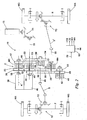
- FIG 2 there is shown an embodiment of a transmission 10 according to the invention, again for a vehicle. Similar parts to those depicted in figure 1 are given the same references.
- the gear ratio selection apparatus C is capable of selecting three alternative gear ratios when the transmission 10 is operated in mechanical drive mode.
- a first gear ratio is selectable by engaging a first power-shift clutch device 32, so that drive is transmitted from the first input member 15, through first and second permanently meshing gears 22, 34 carried respectively to rotate with the first input member 15 and a first lay shaft 30, to a first drive shaft 29.
- the first drive shaft 29 is in line with, and in fact one with the output member 25.
- a second gear ratio is selectable by alternatively engaging a second power-shift clutch device 24 of the mechanical drive train so that drive is transmitted from the first input member 15, through third and fourth permanently meshing gears 35, 36 carried respectively to rotate with a second lay shaft 23, and the first drive shaft 29, to the first drive shaft 29.
- a third gear ratio is selectable by alternatively engaging a third power-shift clutch device M3 of the mechanical drive train so that drive is transmitted from the first input member 15. via the permanently meshing gears 16, 17 which transmit drive to the hydraulic pump 18, and which are carried respectively to rotate with the first input member 15 and the pump shaft 19, and a third lay shaft 33 of the mechanical drive train.
- the third lay shaft 33 carries a fifth gear 38 which is in permanent mesh with the third gear 35 carried on the second lay shaft 23.
- the first input member 15 is driven via a gear train T1 from the engine 13 which is transversely mounted of the vehicle.
- the output member 25 of the transmission 10 is connected via drive shafts S and a further gear train T2 to drive an axle F carrying front wheels W1, W2 of the ground engaging driven structure 12.
- the fourth gear 36 of the mechanical drive train which is carried to rotate with the first drive shaft 29 and hence the output member 25, is in permanent mesh with a seventh gear 50 which is carried on a, fourth lay shaft 51.
- a fourth power-shift clutch device M4 is provided which when engaged, couples the fourth lay shaft 51 to a four wheel drive, second output member 55, which is coupled in turn via a shaft S' and yet further gear train T3, to a rear axle R which carries rear wheels W3, W4.
- two or four wheel drive may be selected upon engaging the fourth power-shift clutch device M4 regardless of whether the transmission 10 is in mechanical drive mode, and with any selected gear ratio, or hydrostatic drive mode as will now be explained.
- hydrostatic drive may be engaged by engaging a hydrostatic drive power-shift clutch device 44 which is provided between the hydraulic motor 40 and a second input member 45 which again is a fixed gear carried on a stub shaft.
- hydraulic pump 18 and hydraulic motor 40 are provided as an integrated unit, but could be separate units, as required.
- gear train of permanently meshing gears between the motor output shaft 41 and the output member 25.
- This includes a motor output gear 58 which is carried to rotate with the motor shaft 41, an idler gear 59 which is in the example mounted on a stub shaft parallel to the output member 25, but could be mounted freely to rotate on the output member 25 as required, and drive gear 60 which is carried on a fifth lay shaft 62 which provides an input part to the hydrostatic drive, power-shift clutch device 44.
- the second input member 45 is coupled to rotate with the fifth lay shaft 62 when the hydrostatic drive, power-shift clutch device 44 is engaged.
- the second input member 45 is in permanent mesh with the seventh gear 50 which is in turn in permanent mesh with the fourth gear 36 which rotates with the first drive shaft 29/output member 25.
- Each power-shift clutch device 32, 24, M3, M4, and 44 are all controlled by a controller 65.
- Each power-shift clutch device will have an actuator which in this example, when energised e.g. with an electrical or preferably hydraulic signal, by the controller 65, engages the respective clutch device, typically against a spring restoring force which disengages the respective clutch device when de-energised.
- the power-shift clutch devices are controlled so that either a selected one of the gear ratio selection power-shift clutch devices 24, 32, M3 is engaged during mechanical drive, whilst the hydrostatic drive, power-shift clutch device 44 is disengaged, or all of the gear ratio selection power-shift clutch devices 24, 32, M3 are disengaged when the hydrostatic drive, power-shift clutch device 44 is engaged to effect hydrostatic drive.
- the four wheel drive power-shift clutch device M4 may be engaged when desired to effect four wheel drive.
- each such power-shift clutch device will have a transition state in which slippage between respective input and output parts of a clutch device is permitted, when changing between fully engaged and fully disengaged states, as is well known in the art.
- the controller 65 may respond to an input signal 70 to engage/disengage respective power-shift clutch devices.
- the input signal 70 may be manually generated by an operator operating vehicle transmission controls, or the input signal 70 may be indicative of the vehicle's speed so that the driving mode may be changed between mechanical drive mode and hydrostatic drive mode automatically at a vehicle threshold speed e.g. of a few kilometres per hour.
- the controller 65 may select hydrostatic drive mode by engaging the hydrostatic drive, power-shift clutch device 44, and disengaging or maintaining disengagement of the gear ratio selection power-shift clutch devices 24, 32, M3 of the mechanical drive train.
- the input signal 70 may be a continuous input from a speed sensor for example, and as the vehicle accelerates to the threshold speed this controller 65 may respond to the threshold speed being reached by changing drive mode to mechanical drive mode by disengaging the hydrostatic drive mode power-shift clutch 44 and engaging a (lowest speed ratio) selected gear ratio power-shift clutch device e.g. the first clutch device 32.
- the controller 65 may effect a change in selected gear ratio by engaging a different gear ratio selection power-shift clutch device of the mechanical drive train, and disengaging the then engaged power-shift clutch device.
- the controller 65 may select a lower gear ratio as a lower speed threshold is reached, and when the vehicle has slowed sufficiently, below a drive mode change threshold speed, hydrostatic drive mode may again be effected and mechanical drive mode suspended.
- the input 70 to the controller 65 to change drive mode or gear ratio may be effected by an intelligent speed sensor only as a threshold speed is reached, and depending upon whether the vehicle is accelerating or decelerating.
- an operator may select two or four wheel drive by disengaging/engaging the four wheel drive power-shift clutch device M4, or this too may be selected automatically by the controller 65 according to programmed logic.
Landscapes
- Engineering & Computer Science (AREA)
- Mechanical Engineering (AREA)
- Chemical & Material Sciences (AREA)
- Combustion & Propulsion (AREA)
- Transportation (AREA)
- General Engineering & Computer Science (AREA)
- Control Of Transmission Device (AREA)
- Structure Of Transmissions (AREA)
- Arrangement Of Transmissions (AREA)
Claims (10)
- Getriebe (10) für ein Fahrzeug, welches eine mit dem Boden in Eingriff kommende Struktur (12) enthält, die von einem Abtriebselement (25) des Getriebes (10) antreibbar ist, wobei das Getriebe (10) ein erstes Antriebselement (15), das mit einem Antriebsaggregat (13) verbindbar ist, und ein zweites Antriebselement (45) enthält, das durch den Betrieb eines hydraulischen Antriebsmotors (40) antreibbar ist, und das Getriebe (10) dazu geeignet ist, in mechanischem Antriebsmodus Bewegung vom ersten Antriebselement (15) auf das Abtriebselement (25) und in hydrostatischem Antriebsmodus vom zweiten Antriebselement (45) auf das Abtriebselement (25) zu übertragen, wobei das erste Antriebselement (15) dazu geeignet ist, einen Antriebseingang vom Antriebsaggregat (13) an einen mechanischen Antriebsstrang bereitzustellen, welcher eine Übersetzungs-Auswahlvorrichtung (C) umfasst, und die Übersetzungs-Auswahlvorrichtung (C) für mechanischem Antriebsmodus einen aus einer Vielzahl von alternativen Übersetzungen bereitstellt, die durch Eingriff und/oder Lösen von wenigstens einer Lastschaltkupplung (24, 32, M3) auszuwählen sind, und das zweite Antriebselement (45) über einen Antriebspfad mit dem Abtriebselement (25) verbunden ist, und sich zwischen dem hydraulischen Antriebsmotor (40) und dem zweiten Antriebselement (45) eine Lastschaltkupplung (44) befindet, das dazu geeignet ist, wenn sich das Getriebe im hydrostatischem Antriebsmodus befindet, durch den Betrieb des hydraulischen Antriebsmotors (40) aufgebauten Antrieb an das zweite Antriebselement (45) zu übertragen, wobei der mechanische Antriebsstrang ferner ein erstes Zahnrad (22) enthält, das so befestigt ist, dass es sich mit dem ersten Antriebselement (15) dreht, und das sich in ständigem Zahneingriff mit einem zweiten Zahnrad (34) befindet, das so befestigt ist, dass es sich mit einer ersten Vorgelegewelle (30) dreht, ferner eine erste Lastschaltkupplung (32), die so in Eingriff bringbar ist, dass sie die erste Vorgelegewelle (30) mit einer Antriebswelle (29) verbindet, und die Antriebswelle (29) ein viertes Zahnrad (36) aufweist, das so befestigt ist, dass es sich mit der Antriebswelle (29) dreht und in ständigem Zahneingriff mit einem dritten Zahnrad (35) steht, das so befestigt ist, dass es sich mit einer zweiten Vorgelegewelle (23) dreht, und ferner eine zweite Lastschaltkupplung (24), die so in Eingriff bringbar ist, dass sie die zweite Vorgelegewelle (23) mit dem ersten Antriebselement (15) verbindet, wobei der hydraulische Antriebsmotor (40) des Getriebes (10), wenigstens wenn sich das Getriebe (10) im hydrostatischen Antriebsmodus befindet, mit unter Druck stehendem Hydraulikfluid von einer Hydraulikpumpe (18), die vom Antriebsaggregat (13) antriebbar ist, versehen wird, um den hydraulischen Antriebsmotor (40) anzutreiben, dadurch gekennzeichnet, dass der hydraulische Antriebsmotor (40) und die Hydraulikpumpe (18) jeweils Vorrichtungen variabler Kapazität sind, wobei eine dritte Übersetzung existiert, die durch Eingreifen einer dritten Lastschaltkupplung (M3) des mechanischen Antriebsstrangs auswählbar ist, so dass Antrieb vom ersten Antriebselement (15) über sechste (16) und siebte (17), in ständigem Zahneingriff stehende Zahnräder übertragen wird, die jeweils so getragen werden, dass sie sich mit dem ersten Antriebselement (15) und einer Pumpenwelle (19) drehen, und welche Antrieb auf die Hydraulikpumpe (18) übertragen, und eine dritte Vorgelegewelle (33) des mechanischen Antriebsstrangs die dritte Lastschaltkupplung und ein fünftes Zahnrad (38) trägt, welches in ständigem Zahneingriff mit dem dritten Zahnrad (35) steht, das an der zweiten Vorgelegewelle (23) getragen wird.
- Getriebe nach Anspruch 1, dadurch gekennzeichnet, dass der Betrieb des Getriebes (10) durch eine Steuerung (65) gesteuert wird, welche die Lastschaltkupplungen (24, 32, M3) des mechanischen Antriebsstrangs so betreibt, dass eine Übersetzung ausgewählt wird.
- Getriebe nach Anspruch 2, dadurch gekennzeichnet, dass die Steuerung (65) die Lastschaltkupplungen (24, 32, M3) des mechanischen Antriebsstrangs und die Lastschaltkupplung (44) zwischen dem hydraulischen Antriebsmotor (40) und dem zweiten Antriebselement (45) so betreibt, dass in Erwiderung darauf, dass das Fahrzeug als bei einer Grenzgeschwindigkeit fahrend bestimmt wird, und in Abhängigkeit davon, ob das Fahrzeug beschleunigt oder abbremst, zwischen mechanischem und hydrostatischem Antriebsmodus gewechselt wird.
- Getriebe nach einem der vorherigen Ansprüche, dadurch gekennzeichnet, dass die Hydraulikpumpe permanent mit dem Antriebsaggregat verbindbar ist.
- Getriebe nach einem der vorherigen Ansprüche, dadurch gekennzeichnet, dass das Abtriebselement (25) des Getriebes (10) mit Rädern (W1, W2, W3, W4) und/oder Schienen der mit dem Boden in Eingriff kommenden, angetriebenen Struktur verbindbar ist, direkt oder über eine oder mehrere weitere Getriebekomponenten (T2, T3).
- Getriebe nach einem der vorherigen Ansprüche, dadurch gekennzeichnet, dass die Antriebswelle (29) und das Abtriebselement (25) in Linie sind.
- Getriebe nach Anspruch 6, dadurch gekennzeichnet, dass die Antriebswelle (29) und das Abtriebselement (25) eins sind.
- Getriebe nach einem der vorherigen Ansprüche, dadurch gekennzeichnet, dass der Antriebspfad, entlang dem Antrieb vom zweiten Antriebselement (45) zum Abtriebselement (25) übertragen wird, wenigstens ein Paar ständig in Zahneingriff stehender Zahnräder (50, 36) enthält.
- Getriebe nach Anspruch 8, wobei ein hydrostatischer Antriebsstrang existiert, der ein Zahnrad (58) enthält, das von einer Motorantriebswelle (41) des hydraulischen Antriebsmotors (40) getragen wird, wobei das Zahnrad (58) so befestigt ist, dass es sich mit der Motorantriebswelle (41) dreht, wobei das Zahnrad über wenigstens ein ständig in Zahneingriff stehendes Zahnrad (59, 60) des hydrostatischen Antriebsstrangs mit einer hydrostatischen Antriebsstrang-Vorgelegewelle (62) verbunden ist, wobei die Lastschaltkupplung (44) zwischen dem hydraulischen Antriebsmotor (40) und dem zweiten Antriebselement (45) bei Eingriff die hydrostatische Antriebsstrang-Vorgelegewelle (62) mit dem zweiten Antriebselement (45) koppelt, um einen hydrostatischen Antrieb zu bewirken.
- Verfahren zum Betreiben eines Getriebes (10) nach einem der vorherigen Ansprüche in einem Fahrzeug, wobei das Verfahren das Betrieben des Getriebes (10) in hydrostatischem Antriebsmodus, mit der Lastschaltkupplung (44) zwischen dem hydraulischen Antriebsmotor (40) und dem zweiten Antriebselement (45) in Eingriff und keiner Übersetzung durch die Übersetzungs-Auswahlvorrichtung (C) ausgewählt, und während das Fahrzeug noch fährt, Auswählen einer Übersetzung des mechanischen Antriebsstrangs durch Eingriff und/oder Lösen von wenigstens einer der Lastschaltkupplungen (24, 32, M3) der Übersetzungs-Auswahlvorrichtung (C) und Lösen der Lastschaltkupplung (44) zwischen dem hydraulischen Antriebsmotor (40) und dem zweiten Antriebselement (45) und Fortfahren, das Fahrzeug im mechanischen Antriebsmodus anzutreiben, umfasst.
Applications Claiming Priority (1)
| Application Number | Priority Date | Filing Date | Title |
|---|---|---|---|
| GBGB0910242.7A GB0910242D0 (en) | 2009-06-15 | 2009-06-15 | Hybrid transmission |
Publications (2)
| Publication Number | Publication Date |
|---|---|
| EP2264334A1 EP2264334A1 (de) | 2010-12-22 |
| EP2264334B1 true EP2264334B1 (de) | 2015-07-22 |
Family
ID=40940802
Family Applications (1)
| Application Number | Title | Priority Date | Filing Date |
|---|---|---|---|
| EP10165868.0A Active EP2264334B1 (de) | 2009-06-15 | 2010-06-14 | Hybridgetriebe und Betriebsverfahren eines solchen Getriebes |
Country Status (6)
| Country | Link |
|---|---|
| US (1) | US8667865B2 (de) |
| EP (1) | EP2264334B1 (de) |
| CN (2) | CN106904074B (de) |
| BR (1) | BRPI1002527B1 (de) |
| GB (2) | GB0910242D0 (de) |
| RU (1) | RU2545149C2 (de) |
Families Citing this family (37)
| Publication number | Priority date | Publication date | Assignee | Title |
|---|---|---|---|---|
| GB0910242D0 (en) * | 2009-06-15 | 2009-07-29 | Bamford Excavators Ltd | Hybrid transmission |
| FR2971975B1 (fr) * | 2011-02-28 | 2013-03-01 | Peugeot Citroen Automobiles Sa | Systeme moto propulseur pour vehicule |
| CA2858673C (en) * | 2011-12-09 | 2017-02-21 | Spicer Off-Highway Belgium N.V. | Shifting procedure for powersplit systems |
| PL2954226T3 (pl) * | 2013-02-11 | 2019-04-30 | Dana Italia Spa | Przekładnia hydrostatyczna z bezpośrednim napędem |
| US9597959B2 (en) | 2013-02-11 | 2017-03-21 | Dana Belgium N.V. | Hydrostatic and direct drive transmission |
| EP2984370B1 (de) | 2013-04-12 | 2021-03-03 | DANA ITALIA S.p.A | Hydrostatisches getriebe mit direktantrieb |
| US8984973B1 (en) * | 2013-11-07 | 2015-03-24 | Agco International Gmbh | Multiple speed power take off |
| US9428049B2 (en) | 2014-02-26 | 2016-08-30 | Deere & Company | Multi-mode power trains with direct-drive lock-up |
| WO2015131196A1 (en) | 2014-02-28 | 2015-09-03 | Project Phoenix, LLC | Pump integrated with two independently driven prime movers |
| WO2015148662A1 (en) | 2014-03-25 | 2015-10-01 | Afshari Thomas | System to pump fluid and control thereof |
| EP3134648B1 (de) | 2014-04-22 | 2023-06-14 | Project Phoenix, LLC | Flüssigkeitsabgabesystem mit einer welle mit durchgang |
| EP3149362B1 (de) | 2014-06-02 | 2019-04-10 | Project Phoenix LLC | Hydrostatische getriebeanordnung und system |
| EP3730793B1 (de) | 2014-06-02 | 2022-04-27 | Project Phoenix LLC | Linearaktuatoranordnung und -system |
| KR102316426B1 (ko) | 2014-07-22 | 2021-10-21 | 프로젝트 피닉스, 엘엘씨 | 독립적으로 구동되는 2개의 원동기와 통합된 외부 기어 펌프 |
| US10072676B2 (en) | 2014-09-23 | 2018-09-11 | Project Phoenix, LLC | System to pump fluid and control thereof |
| EP3204647B1 (de) | 2014-10-06 | 2021-05-26 | Project Phoenix LLC | Linearaktuatoranordnung und -system |
| WO2016064569A1 (en) | 2014-10-20 | 2016-04-28 | Afshari Thomas | Hydrostatic transmission assembly and system |
| JP2018508001A (ja) * | 2015-03-13 | 2018-03-22 | ダナ イタリア エス. アール. エル. | 静油圧式および直接駆動トランスミッション |
| TWI704286B (zh) | 2015-09-02 | 2020-09-11 | 美商鳳凰計劃股份有限公司 | 泵送流體之系統及其控制 |
| EP3344874B1 (de) | 2015-09-02 | 2021-01-20 | Project Phoenix LLC | System zum pumpen einer flüssigkeit und steuerung dafür |
| CN108367668B (zh) | 2015-11-04 | 2021-08-24 | 伊顿智能动力有限公司 | 用于商用车动力系统电气化的变速系统 |
| US9605756B1 (en) | 2015-12-08 | 2017-03-28 | Caterpillar Inc. | Hybrid hydrostatic-direct drive transmission |
| AT15564U1 (de) * | 2016-06-21 | 2018-01-15 | Plasser & Theurer Export Von Bahnbaumaschinen Gmbh | Schienenfahrzeug und Verfahren zum Betrieb eines Schienenfahrzeuges |
| EP4070978B1 (de) | 2016-11-01 | 2023-08-09 | Eaton Intelligent Power Limited | Getriebemontiertes elektrisches ladesystem mit rollen bei abgeschaltetem motor und doppelmodus-hlk |
| CN106704562A (zh) * | 2017-02-15 | 2017-05-24 | 苏州萨伯工业设计有限公司 | 机液混合四挡变速箱 |
| US11938825B2 (en) | 2017-11-07 | 2024-03-26 | Eaton Intelligent Power Limited | System and method of a mobile electrical system |
| CN118810420A (zh) | 2017-11-07 | 2024-10-22 | 伊顿智能动力有限公司 | 安装在变速器上的具有双模式负载和发动机关闭动载功率的充电系统 |
| US11084373B2 (en) | 2017-11-07 | 2021-08-10 | Eaton Intelligent Power Limited | Transmission mounted electrical charging system and dual driveline load coupling |
| US11472287B2 (en) | 2017-11-07 | 2022-10-18 | Eaton Intelligent Power Limited | Transmission mounted electrical charging system with improved battery assembly |
| US11124058B2 (en) | 2019-02-07 | 2021-09-21 | Eaton Intelligent Power Limited | Transmission mounted electrical charging system PTO gear arrangement |
| DE112020000911T5 (de) | 2019-03-18 | 2021-11-25 | Eaton Intelligent Power Limited | Getriebemontiertes elektrisches ladesystem einer pto-getriebeanordnung |
| EP4436325A3 (de) | 2019-06-20 | 2024-12-18 | Eaton Intelligent Power Limited | Motorantriebswandler |
| US11607956B2 (en) * | 2019-10-31 | 2023-03-21 | Deere & Company | Trailing vehicle traction control system with a disconnect device |
| EP4179211A1 (de) | 2020-07-08 | 2023-05-17 | Project Phoenix, LLC | Dynamische steuerung von zahnrädern in einer zahnradpumpe mit einer antriebskonfiguration |
| TWI826800B (zh) | 2020-07-08 | 2023-12-21 | 美商鳳凰計劃股份有限公司 | 具有驅動-驅動組態的齒輪泵中之齒輪的動態控制 |
| CN112622599B (zh) * | 2020-12-28 | 2022-06-28 | 潍柴动力股份有限公司 | 一种机械-液压传动系统、其模式切换控制方法及工程机械 |
| GB2602992A (en) * | 2021-01-22 | 2022-07-27 | Bamford Excavators Ltd | A Working Machine |
Family Cites Families (43)
| Publication number | Priority date | Publication date | Assignee | Title |
|---|---|---|---|---|
| US466636A (en) * | 1892-01-05 | Churn | ||
| US3922931A (en) * | 1974-01-04 | 1975-12-02 | Kubota Ltd | Speed change device for tractor transmissions |
| US4043227A (en) * | 1975-08-23 | 1977-08-23 | Caterpillar Tractor Co. | Hydromechanical transmission |
| FR2360439A1 (fr) | 1976-08-06 | 1978-03-03 | Renault | Dispositif de transmission hybride pour vehicules automobiles a moteur thermique |
| US4581949A (en) | 1983-09-15 | 1986-04-15 | Zahnradfabrik Friedrichshafen Ag | Hydrostatic/mechanical transmission system |
| US4658662A (en) * | 1984-04-16 | 1987-04-21 | Rundle Kenneth P | Transmission and PTO system for tractors and utility cycles |
| US4667636A (en) | 1985-03-22 | 1987-05-26 | Toyota Jidosha Kabushiki Kaisha | Fuel injection type internal combustion engine |
| JPS61232925A (ja) * | 1985-04-09 | 1986-10-17 | Nissan Motor Co Ltd | 4輪駆動装置 |
| DE3733883A1 (de) * | 1987-10-07 | 1989-04-27 | Fendt & Co Xaver | Antrieb fuer nutzfahrzeuge |
| SU1593991A2 (ru) * | 1988-09-26 | 1990-09-23 | Г.Р.Родштейн | Гидромеханическа трансмисси транспортного средства |
| DE59007649D1 (de) * | 1989-07-05 | 1994-12-08 | Zahnradfabrik Friedrichshafen | Vielstufiges zahnräderwechselgetriebe. |
| EP0469451B1 (de) * | 1990-07-25 | 1997-02-05 | CLARK-HURTH COMPONENTS S.p.A. | Getriebe mit drei parallelen Wellen, insbesondere für Nutzfahrzeuge |
| JP3216815B2 (ja) | 1991-01-23 | 2001-10-09 | 株式会社小松製作所 | 圧力補償弁を有する油圧回路 |
| JP3375371B2 (ja) * | 1993-04-16 | 2003-02-10 | 株式会社 神崎高級工機製作所 | 作業車両のトランスミッション |
| US5454223A (en) | 1993-05-28 | 1995-10-03 | Dana Corporation | Hydraulic load sensing system with poppet valve having an orifice therein |
| IT1284483B1 (it) | 1996-09-03 | 1998-05-21 | Ingersoll Rand Italiana S P A | Apparecchiatura di trasmissione del moto di tipo idrostatico-meccanico particolarmente cambio idromeccanico per macchine e veicoli |
| US5868640A (en) | 1996-12-04 | 1999-02-09 | Caterpillar Inc. | Hydromechanical transmission having four members and two planetaries |
| DE19734825C1 (de) * | 1997-08-12 | 1999-12-16 | Clark Equipment Belgium Nv | Lastschaltgetriebe für eine fahrbare Arbeitsmaschine |
| JP2002526326A (ja) * | 1998-10-02 | 2002-08-20 | ルーク ラメレン ウント クツプルングスバウ ベタイリグングス コマンディートゲゼルシャフト | 少なくとも2つの軸、及び、電気機械又は自動的なディスククラッチを有する伝動装置 |
| JP4331808B2 (ja) | 1998-10-27 | 2009-09-16 | ヤンマー株式会社 | 油圧−機械式変速機の速度段切換え制御装置 |
| EP1028020A3 (de) * | 1999-02-09 | 2003-03-26 | Tecumseh Products Company | Hydrostatisches Getriebe mit einem zweiteiligen Motor-Pumpen-Aggregat |
| JP2000320644A (ja) * | 1999-05-17 | 2000-11-24 | Kanzaki Kokyukoki Mfg Co Ltd | 車輌の走行用トランスミッション |
| DE10020187A1 (de) * | 2000-04-25 | 2001-10-31 | Getrag Getriebe Zahnrad | Hydraulische Schaltung für ein automatisiertes Doppelkupplungsgetriebe für Kraftfahrzeuge |
| KR100397570B1 (ko) * | 2000-08-09 | 2003-09-13 | 하태환 | 차량용 동력전달장치 |
| US6565471B2 (en) * | 2000-12-19 | 2003-05-20 | Case Corporation | Continuously variable hydro-mechanical transmission |
| JP2002362174A (ja) | 2001-04-03 | 2002-12-18 | Komatsu Ltd | ホイール式走行作業車両 |
| JP3826783B2 (ja) * | 2001-12-13 | 2006-09-27 | いすゞ自動車株式会社 | 車両の動力伝達装置 |
| US6880429B1 (en) * | 2002-04-30 | 2005-04-19 | Caterpillar Inc | Transmission assembly |
| DE10248400A1 (de) | 2002-10-17 | 2004-04-29 | Zf Friedrichshafen Ag | Leistungsverzweigtes stufenloses Automatgetriebe |
| EP1614938A4 (de) * | 2003-04-14 | 2006-08-30 | Kanzaki Kokyukoki Mfg Co Ltd | Laststeuerung für hydraulikgetriebevorrichtung für arbeitsfahrzeug |
| AT414345B (de) | 2004-08-10 | 2013-08-15 | Hofer Forschungs & Entw Gmbh | Leistungsverzweigungsgetriebe für kraftfahrzeuge |
| US7204084B2 (en) | 2004-10-29 | 2007-04-17 | Caterpillar Inc | Hydraulic system having a pressure compensator |
| US20060145482A1 (en) * | 2005-01-06 | 2006-07-06 | Bob Roethler | Vehicle powertrain that compensates for a prime mover having slow transient response |
| JP2006248341A (ja) | 2005-03-09 | 2006-09-21 | Kanzaki Kokyukoki Mfg Co Ltd | 車両用走行伝動装置 |
| US7204185B2 (en) | 2005-04-29 | 2007-04-17 | Caterpillar Inc | Hydraulic system having a pressure compensator |
| JP4821208B2 (ja) * | 2005-08-08 | 2011-11-24 | 日産自動車株式会社 | 車両の駆動力配分装置 |
| DE102005050067A1 (de) * | 2005-10-19 | 2007-05-03 | Zf Friedrichshafen Ag | Automatisiertes Schaltgetriebe und Verfahren zur Schaltsteuerung eines solchen Schaltgetriebes |
| DE102006018435A1 (de) * | 2006-04-20 | 2007-11-08 | Zf Friedrichshafen Ag | Unter Last schaltbares, mehrgängiges Wendegetriebe |
| DE102006038093B4 (de) | 2006-08-14 | 2010-11-11 | Fiedler Maschinenbau Und Technikvertrieb Gmbh | Antriebssystem für einen Schmalspurgeräteträger |
| WO2008133805A2 (en) | 2007-04-10 | 2008-11-06 | Regents Of The University Of Minnesota | Hydro-mechanical hydraulic hybrid drive train with independent wheel torque control |
| US20080295681A1 (en) | 2007-05-31 | 2008-12-04 | Caterpillar Inc. | Hydraulic system having an external pressure compensator |
| EP2189666B1 (de) | 2008-11-20 | 2011-07-27 | Bosch Rexroth Oil Control S.p.A. | Hydraulische Vorrichtung zur Steuerung eines Stellantriebes |
| GB0910242D0 (en) * | 2009-06-15 | 2009-07-29 | Bamford Excavators Ltd | Hybrid transmission |
-
2009
- 2009-06-15 GB GBGB0910242.7A patent/GB0910242D0/en not_active Ceased
-
2010
- 2010-06-14 GB GB1009908.3A patent/GB2471188B/en active Active
- 2010-06-14 EP EP10165868.0A patent/EP2264334B1/de active Active
- 2010-06-14 BR BRPI1002527-8A patent/BRPI1002527B1/pt active IP Right Grant
- 2010-06-14 US US12/815,237 patent/US8667865B2/en active Active
- 2010-06-15 RU RU2010123996/11A patent/RU2545149C2/ru active
- 2010-06-17 CN CN201611177739.5A patent/CN106904074B/zh active Active
- 2010-06-17 CN CN2010102074641A patent/CN101922542A/zh active Pending
Also Published As
| Publication number | Publication date |
|---|---|
| RU2545149C2 (ru) | 2015-03-27 |
| BRPI1002527A2 (pt) | 2013-11-26 |
| CN106904074A (zh) | 2017-06-30 |
| BRPI1002527B1 (pt) | 2020-11-10 |
| GB201009908D0 (en) | 2010-07-21 |
| CN101922542A (zh) | 2010-12-22 |
| CN106904074B (zh) | 2019-12-06 |
| US8667865B2 (en) | 2014-03-11 |
| US20110030505A1 (en) | 2011-02-10 |
| GB2471188A (en) | 2010-12-22 |
| GB2471188B (en) | 2014-12-24 |
| RU2010123996A (ru) | 2011-12-20 |
| GB0910242D0 (en) | 2009-07-29 |
| EP2264334A1 (de) | 2010-12-22 |
Similar Documents
| Publication | Publication Date | Title |
|---|---|---|
| US8667865B2 (en) | Hybrid transmission | |
| EP2798240B1 (de) | Hydromechanisches stufenloses getriebe zur erreichung einer hohen drehmomentleistung | |
| KR101403121B1 (ko) | 트랙터의 전동 장치 | |
| US9599009B2 (en) | Reversible mechanical fan | |
| CN103261737A (zh) | 用于电动车辆和燃料电池混合动力车辆的无液压多档变速器及其换档系统 | |
| EP2807404B1 (de) | Verfahren zum betreiben einer fahrzeugantriebsleitung | |
| EP3168498A1 (de) | Hydromechanische getriebeanordnung mit geteilter leistungsverzweigung | |
| JP2010209990A (ja) | 作業機 | |
| EP2954226B1 (de) | Hydrostatisches und direktantriebsgetriebe | |
| CN105531508B (zh) | 直接驱动的静压变速器 | |
| EP1554920B1 (de) | Zweiwegeantrieb für eine Trommel einer Erntemaschine und Verfahren zum Trommelverzögern | |
| CN211009795U (zh) | 平地机 | |
| CN101806349B (zh) | 履带式行走动力传动装置 | |
| JP2011196518A (ja) | 作業車両 | |
| CN204077371U (zh) | 大型谷物联合收割机用两档液压驱动桥总成 | |
| JP3940223B2 (ja) | 作業車両の変速操作機構 | |
| CN201677742U (zh) | 履带式行走动力传动装置 | |
| CN217917618U (zh) | 驱动总成、动力系统及作业机械 | |
| CN213199454U (zh) | 一种纯电动环卫车动力系统及其变速装置及纯电动环卫车 | |
| CN104154201A (zh) | 用于全轮驱动工作机的静液压行驶驱动装置 | |
| JP3375371B2 (ja) | 作業車両のトランスミッション | |
| JPH0544815A (ja) | 装輪車両用変速装置 | |
| JP4117072B2 (ja) | 油圧−機械式変速機のエンジンとの連携制御方法 | |
| JP2996948B2 (ja) | 機械油圧式伝動装置 | |
| EP1806522A2 (de) | Mechanischer/hydrostatischer Antrieb mit elektronischer Steuerung für Landwirtschaftsfahrzeuge und Traktoren |
Legal Events
| Date | Code | Title | Description |
|---|---|---|---|
| PUAI | Public reference made under article 153(3) epc to a published international application that has entered the european phase |
Free format text: ORIGINAL CODE: 0009012 |
|
| AK | Designated contracting states |
Kind code of ref document: A1 Designated state(s): AL AT BE BG CH CY CZ DE DK EE ES FI FR GB GR HR HU IE IS IT LI LT LU LV MC MK MT NL NO PL PT RO SE SI SK SM TR |
|
| AX | Request for extension of the european patent |
Extension state: BA ME RS |
|
| 17P | Request for examination filed |
Effective date: 20110622 |
|
| 17Q | First examination report despatched |
Effective date: 20110905 |
|
| GRAP | Despatch of communication of intention to grant a patent |
Free format text: ORIGINAL CODE: EPIDOSNIGR1 |
|
| INTG | Intention to grant announced |
Effective date: 20150202 |
|
| RBV | Designated contracting states (corrected) |
Designated state(s): AL AT BE BG CH CY CZ DE DK EE ES FI FR GR HR HU IE IS IT LI LT LU LV MC MK MT NL NO PL PT RO SE SI SK SM TR |
|
| GRAS | Grant fee paid |
Free format text: ORIGINAL CODE: EPIDOSNIGR3 |
|
| GRAA | (expected) grant |
Free format text: ORIGINAL CODE: 0009210 |
|
| AK | Designated contracting states |
Kind code of ref document: B1 Designated state(s): AL AT BE BG CH CY CZ DE DK EE ES FI FR GR HR HU IE IS IT LI LT LU LV MC MK MT NL NO PL PT RO SE SI SK SM TR |
|
| REG | Reference to a national code |
Ref country code: CH Ref legal event code: EP |
|
| REG | Reference to a national code |
Ref country code: IE Ref legal event code: FG4D |
|
| REG | Reference to a national code |
Ref country code: AT Ref legal event code: REF Ref document number: 738112 Country of ref document: AT Kind code of ref document: T Effective date: 20150815 |
|
| REG | Reference to a national code |
Ref country code: DE Ref legal event code: R096 Ref document number: 602010026011 Country of ref document: DE |
|
| REG | Reference to a national code |
Ref country code: AT Ref legal event code: MK05 Ref document number: 738112 Country of ref document: AT Kind code of ref document: T Effective date: 20150722 |
|
| REG | Reference to a national code |
Ref country code: LT Ref legal event code: MG4D |
|
| REG | Reference to a national code |
Ref country code: NL Ref legal event code: MP Effective date: 20150722 |
|
| REG | Reference to a national code |
Ref country code: CH Ref legal event code: NV Representative=s name: AMMANN PATENTANWAELTE AG BERN, CH |
|
| PG25 | Lapsed in a contracting state [announced via postgrant information from national office to epo] |
Ref country code: LT Free format text: LAPSE BECAUSE OF FAILURE TO SUBMIT A TRANSLATION OF THE DESCRIPTION OR TO PAY THE FEE WITHIN THE PRESCRIBED TIME-LIMIT Effective date: 20150722 Ref country code: GR Free format text: LAPSE BECAUSE OF FAILURE TO SUBMIT A TRANSLATION OF THE DESCRIPTION OR TO PAY THE FEE WITHIN THE PRESCRIBED TIME-LIMIT Effective date: 20151023 Ref country code: FI Free format text: LAPSE BECAUSE OF FAILURE TO SUBMIT A TRANSLATION OF THE DESCRIPTION OR TO PAY THE FEE WITHIN THE PRESCRIBED TIME-LIMIT Effective date: 20150722 Ref country code: NO Free format text: LAPSE BECAUSE OF FAILURE TO SUBMIT A TRANSLATION OF THE DESCRIPTION OR TO PAY THE FEE WITHIN THE PRESCRIBED TIME-LIMIT Effective date: 20151022 Ref country code: LV Free format text: LAPSE BECAUSE OF FAILURE TO SUBMIT A TRANSLATION OF THE DESCRIPTION OR TO PAY THE FEE WITHIN THE PRESCRIBED TIME-LIMIT Effective date: 20150722 |
|
| PG25 | Lapsed in a contracting state [announced via postgrant information from national office to epo] |
Ref country code: PT Free format text: LAPSE BECAUSE OF FAILURE TO SUBMIT A TRANSLATION OF THE DESCRIPTION OR TO PAY THE FEE WITHIN THE PRESCRIBED TIME-LIMIT Effective date: 20151123 Ref country code: SE Free format text: LAPSE BECAUSE OF FAILURE TO SUBMIT A TRANSLATION OF THE DESCRIPTION OR TO PAY THE FEE WITHIN THE PRESCRIBED TIME-LIMIT Effective date: 20150722 Ref country code: HR Free format text: LAPSE BECAUSE OF FAILURE TO SUBMIT A TRANSLATION OF THE DESCRIPTION OR TO PAY THE FEE WITHIN THE PRESCRIBED TIME-LIMIT Effective date: 20150722 Ref country code: PL Free format text: LAPSE BECAUSE OF FAILURE TO SUBMIT A TRANSLATION OF THE DESCRIPTION OR TO PAY THE FEE WITHIN THE PRESCRIBED TIME-LIMIT Effective date: 20150722 Ref country code: ES Free format text: LAPSE BECAUSE OF FAILURE TO SUBMIT A TRANSLATION OF THE DESCRIPTION OR TO PAY THE FEE WITHIN THE PRESCRIBED TIME-LIMIT Effective date: 20150722 Ref country code: IS Free format text: LAPSE BECAUSE OF FAILURE TO SUBMIT A TRANSLATION OF THE DESCRIPTION OR TO PAY THE FEE WITHIN THE PRESCRIBED TIME-LIMIT Effective date: 20151122 Ref country code: AT Free format text: LAPSE BECAUSE OF FAILURE TO SUBMIT A TRANSLATION OF THE DESCRIPTION OR TO PAY THE FEE WITHIN THE PRESCRIBED TIME-LIMIT Effective date: 20150722 |
|
| REG | Reference to a national code |
Ref country code: DE Ref legal event code: R097 Ref document number: 602010026011 Country of ref document: DE |
|
| PG25 | Lapsed in a contracting state [announced via postgrant information from national office to epo] |
Ref country code: CZ Free format text: LAPSE BECAUSE OF FAILURE TO SUBMIT A TRANSLATION OF THE DESCRIPTION OR TO PAY THE FEE WITHIN THE PRESCRIBED TIME-LIMIT Effective date: 20150722 Ref country code: EE Free format text: LAPSE BECAUSE OF FAILURE TO SUBMIT A TRANSLATION OF THE DESCRIPTION OR TO PAY THE FEE WITHIN THE PRESCRIBED TIME-LIMIT Effective date: 20150722 Ref country code: SK Free format text: LAPSE BECAUSE OF FAILURE TO SUBMIT A TRANSLATION OF THE DESCRIPTION OR TO PAY THE FEE WITHIN THE PRESCRIBED TIME-LIMIT Effective date: 20150722 Ref country code: DK Free format text: LAPSE BECAUSE OF FAILURE TO SUBMIT A TRANSLATION OF THE DESCRIPTION OR TO PAY THE FEE WITHIN THE PRESCRIBED TIME-LIMIT Effective date: 20150722 |
|
| PLBE | No opposition filed within time limit |
Free format text: ORIGINAL CODE: 0009261 |
|
| STAA | Information on the status of an ep patent application or granted ep patent |
Free format text: STATUS: NO OPPOSITION FILED WITHIN TIME LIMIT |
|
| PG25 | Lapsed in a contracting state [announced via postgrant information from national office to epo] |
Ref country code: RO Free format text: LAPSE BECAUSE OF FAILURE TO SUBMIT A TRANSLATION OF THE DESCRIPTION OR TO PAY THE FEE WITHIN THE PRESCRIBED TIME-LIMIT Effective date: 20150722 |
|
| REG | Reference to a national code |
Ref country code: FR Ref legal event code: PLFP Year of fee payment: 7 |
|
| 26N | No opposition filed |
Effective date: 20160425 |
|
| PG25 | Lapsed in a contracting state [announced via postgrant information from national office to epo] |
Ref country code: SI Free format text: LAPSE BECAUSE OF FAILURE TO SUBMIT A TRANSLATION OF THE DESCRIPTION OR TO PAY THE FEE WITHIN THE PRESCRIBED TIME-LIMIT Effective date: 20150722 |
|
| PG25 | Lapsed in a contracting state [announced via postgrant information from national office to epo] |
Ref country code: BE Free format text: LAPSE BECAUSE OF FAILURE TO SUBMIT A TRANSLATION OF THE DESCRIPTION OR TO PAY THE FEE WITHIN THE PRESCRIBED TIME-LIMIT Effective date: 20150722 |
|
| PG25 | Lapsed in a contracting state [announced via postgrant information from national office to epo] |
Ref country code: MC Free format text: LAPSE BECAUSE OF FAILURE TO SUBMIT A TRANSLATION OF THE DESCRIPTION OR TO PAY THE FEE WITHIN THE PRESCRIBED TIME-LIMIT Effective date: 20150722 |
|
| REG | Reference to a national code |
Ref country code: IE Ref legal event code: MM4A |
|
| PG25 | Lapsed in a contracting state [announced via postgrant information from national office to epo] |
Ref country code: IE Free format text: LAPSE BECAUSE OF NON-PAYMENT OF DUE FEES Effective date: 20160614 |
|
| REG | Reference to a national code |
Ref country code: FR Ref legal event code: PLFP Year of fee payment: 8 |
|
| PG25 | Lapsed in a contracting state [announced via postgrant information from national office to epo] |
Ref country code: NL Free format text: LAPSE BECAUSE OF FAILURE TO SUBMIT A TRANSLATION OF THE DESCRIPTION OR TO PAY THE FEE WITHIN THE PRESCRIBED TIME-LIMIT Effective date: 20150722 |
|
| PG25 | Lapsed in a contracting state [announced via postgrant information from national office to epo] |
Ref country code: CY Free format text: LAPSE BECAUSE OF FAILURE TO SUBMIT A TRANSLATION OF THE DESCRIPTION OR TO PAY THE FEE WITHIN THE PRESCRIBED TIME-LIMIT Effective date: 20150722 Ref country code: SM Free format text: LAPSE BECAUSE OF FAILURE TO SUBMIT A TRANSLATION OF THE DESCRIPTION OR TO PAY THE FEE WITHIN THE PRESCRIBED TIME-LIMIT Effective date: 20150722 Ref country code: HU Free format text: LAPSE BECAUSE OF FAILURE TO SUBMIT A TRANSLATION OF THE DESCRIPTION OR TO PAY THE FEE WITHIN THE PRESCRIBED TIME-LIMIT; INVALID AB INITIO Effective date: 20100614 |
|
| REG | Reference to a national code |
Ref country code: FR Ref legal event code: PLFP Year of fee payment: 9 |
|
| PG25 | Lapsed in a contracting state [announced via postgrant information from national office to epo] |
Ref country code: LU Free format text: LAPSE BECAUSE OF NON-PAYMENT OF DUE FEES Effective date: 20160614 Ref country code: MT Free format text: LAPSE BECAUSE OF NON-PAYMENT OF DUE FEES Effective date: 20160630 Ref country code: TR Free format text: LAPSE BECAUSE OF FAILURE TO SUBMIT A TRANSLATION OF THE DESCRIPTION OR TO PAY THE FEE WITHIN THE PRESCRIBED TIME-LIMIT Effective date: 20150722 Ref country code: MK Free format text: LAPSE BECAUSE OF FAILURE TO SUBMIT A TRANSLATION OF THE DESCRIPTION OR TO PAY THE FEE WITHIN THE PRESCRIBED TIME-LIMIT Effective date: 20150722 |
|
| PG25 | Lapsed in a contracting state [announced via postgrant information from national office to epo] |
Ref country code: BG Free format text: LAPSE BECAUSE OF FAILURE TO SUBMIT A TRANSLATION OF THE DESCRIPTION OR TO PAY THE FEE WITHIN THE PRESCRIBED TIME-LIMIT Effective date: 20150722 |
|
| PG25 | Lapsed in a contracting state [announced via postgrant information from national office to epo] |
Ref country code: AL Free format text: LAPSE BECAUSE OF FAILURE TO SUBMIT A TRANSLATION OF THE DESCRIPTION OR TO PAY THE FEE WITHIN THE PRESCRIBED TIME-LIMIT Effective date: 20150722 |
|
| PGFP | Annual fee paid to national office [announced via postgrant information from national office to epo] |
Ref country code: CH Payment date: 20190619 Year of fee payment: 10 |
|
| REG | Reference to a national code |
Ref country code: CH Ref legal event code: PL |
|
| PG25 | Lapsed in a contracting state [announced via postgrant information from national office to epo] |
Ref country code: CH Free format text: LAPSE BECAUSE OF NON-PAYMENT OF DUE FEES Effective date: 20200630 Ref country code: LI Free format text: LAPSE BECAUSE OF NON-PAYMENT OF DUE FEES Effective date: 20200630 |
|
| P01 | Opt-out of the competence of the unified patent court (upc) registered |
Effective date: 20230522 |
|
| PGFP | Annual fee paid to national office [announced via postgrant information from national office to epo] |
Ref country code: DE Payment date: 20250618 Year of fee payment: 16 |
|
| PGFP | Annual fee paid to national office [announced via postgrant information from national office to epo] |
Ref country code: FR Payment date: 20250624 Year of fee payment: 16 |
|
| PGFP | Annual fee paid to national office [announced via postgrant information from national office to epo] |
Ref country code: IT Payment date: 20250619 Year of fee payment: 16 |