EP2262397B1 - Vorrichtung zur öffnung und schliessung eines beweglichen teils eines möbelstücks - Google Patents
Vorrichtung zur öffnung und schliessung eines beweglichen teils eines möbelstücks Download PDFInfo
- Publication number
- EP2262397B1 EP2262397B1 EP09764741A EP09764741A EP2262397B1 EP 2262397 B1 EP2262397 B1 EP 2262397B1 EP 09764741 A EP09764741 A EP 09764741A EP 09764741 A EP09764741 A EP 09764741A EP 2262397 B1 EP2262397 B1 EP 2262397B1
- Authority
- EP
- European Patent Office
- Prior art keywords
- closing
- opening
- slider
- moveable part
- furniture according
- Prior art date
- Legal status (The legal status is an assumption and is not a legal conclusion. Google has not performed a legal analysis and makes no representation as to the accuracy of the status listed.)
- Not-in-force
Links
Images


Classifications
-
- A—HUMAN NECESSITIES
- A47—FURNITURE; DOMESTIC ARTICLES OR APPLIANCES; COFFEE MILLS; SPICE MILLS; SUCTION CLEANERS IN GENERAL
- A47B—TABLES; DESKS; OFFICE FURNITURE; CABINETS; DRAWERS; GENERAL DETAILS OF FURNITURE
- A47B88/00—Drawers for tables, cabinets or like furniture; Guides for drawers
- A47B88/40—Sliding drawers; Slides or guides therefor
- A47B88/453—Actuated drawers
- A47B88/46—Actuated drawers operated by mechanically-stored energy, e.g. by springs
- A47B88/47—Actuated drawers operated by mechanically-stored energy, e.g. by springs having both self-opening and self-closing mechanisms which interact with each other
Definitions
- the present invention refers to a device for opening and closing a movable part of a furniture unit. It is common knowledge that there have been devices on the market for some time now that achieve the virtually automatic opening and/or closing of movable parts of furniture units, such as a door or a drawer in a furniture unit.
- a device called a ratchet which substantially comprises thrust means that are released by exerting a mild pressure on the drawer and, when released, under an elastic force they confer a thrust on the drawer that determines its controlled displacement, thereby enabling the user to grasp the drawer and open it completely, especially in the case of drawers without handles.
- a self-closing device is used that is normally associated with the fixed drawer guide and consists of a body for supporting a slider that is movable inside a groove provided in said body, between two stable terminal positions.
- the slider normally moves inside the groove in contrast and due to the action of a spring that is activated by drawing means integrally attached to the withdrawable drawer guide.
- the opening of the drawer determines the activation of the self-closing device, which takes over, when the drawer is closed again, in the final stretch of its stroke - by means of a pin, for instance - returning it to the completely closed position due to the effect of the spring.
- the movable part consists of a drawer
- the self-closing device can be arranged indifferently in various positions in relation to the furniture unit, e.g. in line with guides that enable its movement.
- the device In the case of doors swinging by means of hinges, on the other hand, the device should preferably be located on the part of the furniture unit opposite to the one where the hinges are located, i.e. where it is possible, by means of a pressure exerted from the outside by the user, to obtain a displacement of the door sufficient to enable the device.
- the door is opened by completely separating its edge from the side of the furniture unit against which it abuts, with a consequently more complicated interaction between the drawing means and the slider of the self-closing system.
- hinge there are various different types of hinge commercially available, some in particular in which an elastic device is integrated for providing the thrust in the door-closing direction, possibly assisted by a decelerator device, or fitted with an elastic device for inducing a thrust in the door-opening direction, possibly for associating with the previously-described ratchet devices.
- DE 199 35120 discloses a device for opening and closing a moveable part of a furniture according to preamble of claim 1.
- the technical aim of the present invention is consequently to produce a device for opening and closing a movable part of a furniture unit that enables the technical drawbacks of the known art to be overcome.
- one object of the invention is to produce a device for opening and closing a movable part of a furniture unit that is reliable and of extremely straightforward functional design, guaranteeing its long-term efficiency without the need for any type of ordinary or extraordinary maintenance two achieve this end.
- Another object of the invention is to produce a device for opening and closing a movable part of a furniture unit that can be installed without difficulty even by unskilled personnel, consequently also enabling its replacement or adjustment by the user if necessary, and that, among other things, has a limited cost, which can facilitate its diffusion on the market.
- Another, not necessarily last object of the invention is to produce a device for opening and closing a movable part of a furniture unit that can be installed on any type of furniture unit, occupying a limited amount of space.
- the device according to the invention can generally be attached to movable parts of furniture units, including drawers, for instance, but it is particularly suitable for opening doors swinging around a vertical or horizontal axis.
- the closing of the movable parts of furniture units is instead preferably assisted by or entrusted to known closing devices integrated in the normal guides or hinges with which these parts are provided to enable their movement.
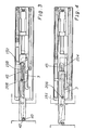
- a device for opening and closing a movable part of a furniture unit according to the invention is shown, globally indicated by the reference number 1.
- the movable part 103 of the furniture unit to which reference is made herein, in this specific preferred embodiment, is a door swinging in relation to the body of a furniture unit, but more in general it might equally be the front of a drawer or other such parts.
- the device 1 comprises a body 208; associated with the fixed part of the furniture unit 116, for supporting a slider 3 reversibly sliding along a sliding axis 100 in contrast and due to the action of first elastic mean, and in particular of a spring 5. More precisely, the slider 3 is slidingly engaged in a groove 204 in the supporting body 208 that extends in the direction, of the sliding axis 100, and that is engageable with drawing means installed on a drawing element 205 sliding in the direction of the sliding axis 100 and integral or reversibly couplable with the movable part 103 of the furniture unit.
- the drawing element 205 is slidingly supported inside a guide element 114 provided in a cover element 215 on the supporting body 208.
- the drawing element 205 extends longitudinally in the direction of the sliding axis 100 and has a "C"-shaped cross-section.
- the supporting body 208 comprises first displacement means suitable for moving the drawing means so as to release said drawing means and the slider 3 from their mutual engagement.
- the drawing means are advantageously supported by the drawing element 205 so that they are movable transversely to the direction of the sliding axis 100.
- the drawing means comprise a drawing pin 206 attached to a lever 43 that is hinged at 44 to the drawing element 205 so as to enable a swinging action.
- the lever 43 carries an element 42 for mechanically hooking to the movable part 103, e.g. by means of an element 41 attached to the movable part 103 and provided with two flanges that hold a cross pin 40 hooked up by the hooking element 42.
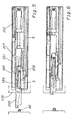
- Figures 12 and 13 show a second embodiment of the invention that essentially differs from the first only in terms of the structure of the drawing element 205, in that the system for hooking up the movable part 103 is of magnetic type.
- the lever 43 is a simple lever with the drawing pin 206 fitted at its free end.
- the magnetic element 300 can be carried by the movable part 103, or by the front end of the drawing element 205.
- the supporting body 208 includes a track 45 along which the free end of the drawing pin 206 is guided.
- the first displacement means consisting of at least one first stretch 151 and one second stretch 152 of the track 45, extend in a sloping manner transversely to the direction of the sliding axis 100 and they are connected by a third stretch 153 and a fourth stretch 154 of said track that extend parallel to the direction of the sliding axis 100.
- the track 45 comprises two adjacent parallel rails that extend along a closed path with a quadrangular shape.
- the first embodiment of the present invention enables the mechanical control of the engagement and disengagement of the device 1 to and from a movable part 103 of a furniture unit using the track 45 provided for the drawing pin 206, and it is preferable to the second embodiment of the present invention because it avoids the need to use magnetic couplings, which are less reliable and noisier.
- the groove 204 comprises second means for displacing the slider 3 transversely to the sliding axis 100, and suitable for engaging in a releasable manner with means for guiding the slider 3.
- the second displacement means comprise a front bend 155 in the groove 204, while the guide means comprise a front guide pin 156 and a rear guide pin 157, carried permanently by the slider 3 and slidingly inside the groove 204.
- the slider 3 also comprises a recessed surface 158, limited by a front edge 159 and a rear edge 160 for intercepting the drawing pin 206, with a rear cavity 161, where the drawing pin 206 is releasably engageable.
- the device 1 in which the device 1 is attached to a furniture unit fitted with hinges that exert a thrust in the direction for closing the movable part 103, there is also a second slider 101 carried by the supporting body 208 and reversibly movable in the direction of the sliding axis 100 in contrast and due to the action of second elastic means, and particularly of a second spring 102.
- the second slider 101 is engageable with second drawing means provided on the drawing element 205.
- the second drawing means comprise a fin 207 that extends laterally from the drawing element 205 and engages slidingly in a guiding slot 108 provided in the second slider 101.
- the device 1 also includes an elastically yielding stop element 209 against which the drawing element 205 abuts directly or indirectly before it engages with the drawing means in the first displacement means, and it is fitted with thrust means that push the drawing element in the opening direction.
- These thrust means preferably push the drawing element 205 only over one stretch of its displacement stroke.
- the thrust means comprise an ejector contained in the supporting body 208 to the rear of the drawing element 205.
- the ejector includes a portion 20 for accommodating a stem 20b that is movable in the direction of the sliding axis 100 in contrast and due to the action of a spring (not shown) and it is designed to take effect on the rear base of the drawing element 205 to generate an initial opening stroke of the movable part 103 with a greater force than is exerted thereon by any independent closing devices, such as those integrated in the hinges, for instance.
- the ejector has a force of expulsion that is weaker than the elastic force of the first elastic means so that, when the slider 3 is free to slide, the latter are able to bring the drawing element 205, with which the slider 3 engages, into the position corresponding to the closed position of the movable part 103 ( Fig. 6 ).
- the drawing element 205 consequently abuts indirectly against the stop element 209, i.e. with the interposition of the ejector that, in the closed position, has its stem 20b completely withdrawn inside the portion 20, thus forming a rigid unit.
- the portion 20 of the ejector is pushed by the elastically yielding stop element 209 against a fixed stop element 50 on the supporting body 208 with a greater force than is exerted by the first elastic means, so that it can withdraw in the direction of the sliding axis 100 under the effect of an external action contrasting the elastically yielding stop element 209, that in the case in point is a spring interposed between the rear base of the portion 20 and the bottom wall of the fixed guide 162 along which the portion 20 is movable.
- the drawing pin 206 engages in the rear cavity 161 of the slider 3, that is retained in a position at rest in which the drawing element 205 abuts against the stem 20b of the ejector, which in turn abuts against the elastically yielding stop element 209, which is not compressed, but only preloaded so as to retain the ejector in position against the fixed stop element 15.
- the stem 20b is in a withdrawn position, since the force of the ejector 20 is weaker than the force of the spring 5.
- the spring 5 keeps the slider 3 in its position at the bottom of the groove 204, while the accommodation portion 20 of the ejector returns to its initial position abutting against the fixed stop element 50 and the stem 20b is extracted and thus pushes the drawing element 205 with the drawing pin 206 into the position shown in figure 3 , in which the movable part 103 can be grasped and pulled to open it completely.
- the drawing pin 206 encounters and pushes against the front edge 159 of the slider 3, which is drawn along the groove 204 into the position shown in figure 4 , in which the drawing pin 206 slides along the sloping front wall 151 of the track 45.
- the slider 3 engages with the guide pin 156 in the front bend 155 in the groove 204 and thus remains locked in its position with the spring 5 loaded, the hooking element 42 is disengaged from the pin 40 and the drawing element 205, together with the drawing pin 206, is pushed backwards due to the effect of its drawing fin 207 being engaged with the slider 101 recalled by the spring 102, that was loaded previously., during the extraction of the drawing element 205.
- the drawing pin 206 encounters and pushes against the rear edge 160 of the slider 3, which is thus released from its current position and returns, together with the drawing element 205, to the initial position shown in figure 6 , but with the movable part 103 open. Since the hooking element 42 is raised in this position, the movable part 103 can be closed again normally, by means of the typical closing devices of known type with which it is fitted. Moreover, from its closed position the movable part 103 can also be opened accidentally by pulling it without the device being operated in an anomalous manner, and consequently without it being damaged.
- the device comprising a magnetic hooking system shown in figures 12 and 13 , is also suitable for movable parts of furniture units fitted with guides or hinges and already complete with independent thrust devices in the opening direction, but it, is distinguishable essentially in that the rotation of the lever 43 is exploited only to disengage the drawing pin 206 from the slider, while the drawing element 205 is released from the movable part 103 of the furniture unit when the magnetic connecting force is exceeded by the pulling force exerted by the user and the drawing element 205 is retained at the end of its stroke by the front stop on the slider 101.
- the device according to the invention is particularly advantageous in enabling the simple and practical opening and closing of a door or drawer, making it easy for the user to grasp and ensuring a controlled closing action.
Claims (14)
- Vorrichtung (1) zur Öffnung und Schließung eines beweglichen Teils eines Möbelstücks, umfassend - an ein fixiertes Teil des Möbelstücks (116) anschließbar - einen Körper (208) zum Stützen eines Gleitstücks (3), das umkehrbar entlang einer Gleitachse (100) im Gegensatz und infolge der Wirkung eines ersten elastischen Mittels (5) gleitet, wobei das Gleitstück (3) in ein Zugmittel (206) eingreifbar ist, das auf einem Zugelement (205) vorhanden ist, das in Richtung der Gleitachse (100) ganzheitlich oder in einer Art und Weise gleitet, die umkehrbar mit dem beweglichen Teil (103) des Möbelstücks verkuppelbar ist, wobei der Stützkörper (208) ein erstes Bewegungsmittel (45) umfasst, das dazu geeignet ist, das Zugmittel (206) derart zu bewegen, dass das Zugmittel und das Gleitstück (3) aus ihrem gegenseitigen Ineinandergreifen befreit werden, umfassend ein nachgebendes, elastisches Halteelement (209), gegen welches das Zugelement (205) direkt oder indirekt anstößt, bevor es in das Zugmittel im ersten Bewegungsmittel eingreift, dadurch gekennzeichnet, dass es Schubmittel (20, 20b) umfasst, die dazu geeignet sind, das Zugelement (205) direkt oder indirekt in die gegensätzliche Richtung mit einer Kraft zu drücken, die geringer als das Drücken des ersten elastischen Mittels ist.
- Vorrichtung (1) zur Öffnung und Schließung eines beweglichen Teils eines Möbelstücks nach Anspruch 1, dadurch gekennzeichnet, dass die Schubmittel das Zugelement (205) nur für einen Abschnitt der Bewegung drücken.
- Vorrichtung (1) zur Öffnung und Schließung eines beweglichen Teils eines Möbelstücks nach einem oder mehreren der vorangehenden Ansprüche, dadurch gekennzeichnet, dass das Zugmittel vom Zugelement (205) auf bewegliche Art und Weise transversal zur Richtung der Gleitachse (100) gestützt wird.
- Vorrichtung (1) zur Öffnung und Schließung eines beweglichen Teils eines Möbelstücks nach einem oder mehreren der vorangehenden Ansprüche, dadurch gekennzeichnet, dass das Zugmittel einen Zugstift (206) umfasst, der auf einem Hebel (43) fixiert ist, der auf schwingende Art und Weise auf dem Zugelement (205) schwenkbar befestigt ist.
- Vorrichtung (1) zur Öffnung und Schließung eines beweglichen Teils eines Möbelstücks nach Anspruch 4, dadurch gekennzeichnet, dass das erste Bewegungsmittel - in einer Bahn (45), die im Körper (208) des Trägers bereitgestellt ist und entlang der das freie Ende des Zugstifts (206) geführt wird - mindestens einen ersten (151) und einen zweiten (152) Abschnitt der Bahn (45) umfasst, die transversal zur Richtung der Gleitachse (100) sind und mit einem dritten (153) und vierten (154) Abschnitt der Bahn (45) verbunden sind, die sich parallel zur Richtung der Gleitachse (100) ausdehnen.
- Vorrichtung (1) zur Öffnung und Schließung eines beweglichen Teils eines Möbelstücks nach Anspruch 5, dadurch gekennzeichnet, dass die Bahn (45) zwei benachbarte Schienen umfasst, die parallel zueinander sind.
- Vorrichtung (1) zur Öffnung und Schließung eines beweglichen Teils eines Möbelstücks nach einem der Ansprüche 4 bis 6, dadurch gekennzeichnet, dass der Hebel (43) - auf dem gegensätzlichen Arm in Bezug auf den Zugstift (206) - ein Element (42) zum mechanischen Eingreifen in das bewegliche Teil (103) trägt.
- Vorrichtung (1) zur Öffnung und Schließung eines beweglichen Teils eines Möbelstücks nach einem oder mehreren der vorangehenden Ansprüche, dadurch gekennzeichnet, dass sie ein magnetisches Element (300) zum Eingreifen des Zugelements (205) in das bewegliche Teil (103) umfasst.
- Vorrichtung (1) zur Öffnung und Schließung eines beweglichen Teils eines Möbelstücks nach einem oder mehreren der vorangehenden Ansprüche, dadurch gekennzeichnet, dass der Stützkörper (208) eine Nut (204) aufweist, die sich in Richtung der Gleitachse (100) ausdehnt und dass sie - im Bereich des vorderen Endes - ein zweites Mittel zum Bewegen des Gleitstücks (3) in einer Art und Weise umfasst, das transversal zur Gleitachse (100) ist, wobei das Mittel dazu geeignet ist, in einer lösbaren Art und Weise in ein Führungsmittel des Gleitstücks (3) zu greifen.
- Vorrichtung (1) zur Öffnung und Schließung eines beweglichen Teils eines Möbelstücks nach Anspruch 9, dadurch gekennzeichnet, dass das zweite Bewegungsmittel eine vordere Krümmung (155) der Nut (204) umfasst und das Führungsmittel einen vorderen Führungsstift (156) und einen hinteren Führungsstift (157) umfasst, die vom Gleitstück (3) fixiert getragen werden und in der Nut (204) gleiten.
- Vorrichtung (1) zur Öffnung und Schließung eines beweglichen Teils eines Möbelstücks nach einem der Ansprüche 4 bis 7, dadurch gekennzeichnet, dass das Gleitstück (3) eine herabgesenkte Oberfläche (158) umfasst, die durch eine vordere Seite (159) und eine hintere Seite (160) zum Abfangen des Zugstifts (206) begrenzt wird, wobei die herabgesenkte Oberfläche (158) ferner einen vorderen Schlitz aufweist, in dem der Zugstift (206) in einer lösbaren Art und Weise im Eingriff stehen kann.
- Vorrichtung (1) zur Öffnung und Schließung eines beweglichen Teils eines Möbelstücks nach einem oder mehreren der vorangehenden Ansprüche, dadurch gekennzeichnet, dass sie ein zweites Gleitstück (101) umfasst, das vom Stützkörper (208) getragen wird und umkehrbar in Richtung der Gleitachse (100) im Gegensatz und infolge der Wirkung eines zweiten elastischen Mittels gleitet, wobei das zweite Gleitstück (101) in ein zweites Zugmittel eingreifbar ist, das auf dem Zugelement (205) vorhanden ist.
- Vorrichtung (1) zur Öffnung und Schließung eines beweglichen Teils eines Möbelstücks nach einem oder mehreren der vorangehenden Ansprüche, dadurch gekennzeichnet, dass das Schubmittel einen Auswerfer umfasst, der ein Teil (20) zur Aufnahme eines Schafts (20b) umfasst, das in Richtung der Gleitachse (100) beweglich ist, wobei das Aufnahmeteil (20) durch das elastisch nachgebende Halteelement (209) auf solche Art und Weise gegen ein fixiertes Halteelement (50) des Stützkörpers (208) bewegt wird, dass es dazu fähig ist, in Richtung der Gleitachse (100) gegensätzlich zum elastisch nachgebenden Halteelement (209) eingezogen zu werden und wobei der Schaft (20b) dazu geeignet ist, gegen die hintere Basis des Zugelements (205) zu agieren, um einen ersten Lauf zur Öffnung des beweglichen Teils (103) zu erzeugen.
- Vorrichtung (1) zur Öffnung und Schließung eines beweglichen Teils eines Möbelstücks nach Anspruch 13, dadurch gekennzeichnet, dass das elastisch nachgebende Halteelement (209) eine Feder ist, die zwischen der hinteren Basis des Aufnahmeteils (20) und einer unteren Wand einer fixierten Führung (162) liegt, entlang welcher das Aufnahmeteil (20) beweglich ist.
Priority Applications (1)
| Application Number | Priority Date | Filing Date | Title |
|---|---|---|---|
| SI200930218T SI2262397T1 (sl) | 2008-12-12 | 2009-12-07 | Naprava za odpiranje in zapiranje gibljivega dela kosa pohištva |
Applications Claiming Priority (2)
| Application Number | Priority Date | Filing Date | Title |
|---|---|---|---|
| ITMI2008A002196A IT1392184B1 (it) | 2008-12-12 | 2008-12-12 | Dispositivo di apertura e chiusura di una parte spostabile di un mobile |
| PCT/EP2009/008713 WO2010066393A1 (en) | 2008-12-12 | 2009-12-07 | Device for opening and closing a movable part of a furniture unit |
Publications (2)
| Publication Number | Publication Date |
|---|---|
| EP2262397A1 EP2262397A1 (de) | 2010-12-22 |
| EP2262397B1 true EP2262397B1 (de) | 2011-12-28 |
Family
ID=40886846
Family Applications (1)
| Application Number | Title | Priority Date | Filing Date |
|---|---|---|---|
| EP09764741A Not-in-force EP2262397B1 (de) | 2008-12-12 | 2009-12-07 | Vorrichtung zur öffnung und schliessung eines beweglichen teils eines möbelstücks |
Country Status (12)
| Country | Link |
|---|---|
| US (1) | US8764134B2 (de) |
| EP (1) | EP2262397B1 (de) |
| JP (1) | JP5615290B2 (de) |
| KR (1) | KR20110106231A (de) |
| CN (1) | CN102159118B (de) |
| AT (1) | ATE538683T1 (de) |
| BR (1) | BRPI0917872A2 (de) |
| HK (1) | HK1157593A1 (de) |
| IT (1) | IT1392184B1 (de) |
| SI (1) | SI2262397T1 (de) |
| TW (1) | TWI461163B (de) |
| WO (1) | WO2010066393A1 (de) |
Families Citing this family (32)
| Publication number | Priority date | Publication date | Assignee | Title |
|---|---|---|---|---|
| IT1392907B1 (it) * | 2008-09-12 | 2012-04-02 | Salice Arturo Spa | Dispositivo di auto chiusura di un cassetto o di una parte spostabile di un mobile |
| ES2397814T3 (es) * | 2008-10-13 | 2013-03-11 | Arturo Salice S.P.A. | Dispositivo de abertura y cierre automático, particularmente para una parte móvil de un mueble |
| JP5433466B2 (ja) * | 2010-03-17 | 2014-03-05 | 株式会社ニフコ | 摺動補助装置 |
| JP2011196015A (ja) * | 2010-03-17 | 2011-10-06 | Nifco Inc | 摺動補助装置 |
| TWM397194U (en) * | 2010-07-02 | 2011-02-01 | Sun Chain Metal Industry Co Ltd | Automatic opening/closing device of drawer |
| DE102010037826A1 (de) * | 2010-09-24 | 2012-03-29 | Paul Hettich Gmbh & Co. Kg | Selbsteinzugsvorrichtung für ein verschiebbares Möbelteil |
| ITMI20110517A1 (it) * | 2011-03-30 | 2012-10-01 | Salice Arturo Spa | Dispositivo di ritegno per dispositivo di apertura e chiusura automatica per parte spostabile di mobile |
| DE102011122266A1 (de) | 2011-12-23 | 2013-06-27 | Grass Gmbh | Vorrichtung zur Bewegungsbeeinflussung eines Möbelteils, Führungseinheit zur Bewegungsführung eines Möbelteils und Möbel |
| AT511799B1 (de) * | 2011-12-23 | 2013-03-15 | Blum Gmbh Julius | Anordnung zum bewegen eines bewegbaren möbelteils |
| AT511938B1 (de) * | 2012-01-18 | 2013-04-15 | Blum Gmbh Julius | Antriebsvorrichtung für ein bewegbares möbelteil |
| KR101288892B1 (ko) | 2012-02-27 | 2013-07-23 | 박윤식 | 푸시-오픈 장치 및 그것을 구비한 서랍용 슬라이드 구조체 |
| AT512694B1 (de) | 2012-03-16 | 2013-12-15 | Blum Gmbh Julius | Ausstoßvorrichtung für ein bewegbares Möbelteil |
| US9648952B2 (en) | 2012-04-30 | 2017-05-16 | Hardware Resources, Inc. | Pressure release slide latch mechanism |
| US9750347B2 (en) | 2012-04-30 | 2017-09-05 | Hardware Resources, Inc. | Pressure release slide latch mechanism |
| AT512509B1 (de) * | 2012-07-10 | 2013-09-15 | Blum Gmbh Julius | Ausstoßvorrichtung für ein bewegbares Möbelteil |
| US8801120B2 (en) | 2012-09-12 | 2014-08-12 | King Slide Works Co., Ltd. | Self-opening and self-closing slide assembly |
| ITMI20121718A1 (it) * | 2012-10-12 | 2014-04-13 | Salice Arturo Spa | Mobile con almeno un cassetto o simile |
| KR101860713B1 (ko) | 2013-02-23 | 2018-05-24 | 삼성전자주식회사 | 슬라이딩 장치 및 이를 갖는 냉장고 |
| AT514143A1 (de) * | 2013-04-12 | 2014-10-15 | Blum Gmbh Julius | Antriebsvorrichtung für ein bewegbares Möbelteil |
| ITMI20140344U1 (it) * | 2014-11-11 | 2016-05-11 | Bortoluzzi Sistemi Spa | Dispositivo di smorzamento o richiamo per ante scorrevoli |
| DE102015003414B3 (de) * | 2015-03-17 | 2016-06-16 | Günther Zimmer | Kombinierte Beschleunigungs- und Verzögerungsvorrichtung mit Überlastschutz |
| DE202015104430U1 (de) * | 2015-08-21 | 2016-11-22 | Grass Gmbh | Vorrichtung zum Bewegen eines bewegbaren Möbelteils in eine Öffnungsrichtung mit Bezug zu einem Möbelkorpus eines Möbels |
| DE202015104431U1 (de) * | 2015-08-21 | 2016-11-22 | Grass Gmbh | Vorrichtung für die Bewegung eines Möbelteils und Möbel |
| TWI538638B (zh) | 2015-11-12 | 2016-06-21 | 川湖科技股份有限公司 | 用於傢俱組件的驅動機構及方法 |
| TWI536933B (zh) | 2015-11-12 | 2016-06-11 | 川湖科技股份有限公司 | 滑軌總成 |
| TWI532452B (zh) | 2015-11-12 | 2016-05-11 | 川湖科技股份有限公司 | 驅動機構 |
| TWI572304B (zh) | 2016-03-31 | 2017-03-01 | 川湖科技股份有限公司 | 用於傢俱組件的驅動機構及方法 |
| CN107296407B (zh) * | 2016-04-13 | 2019-03-15 | 川湖科技股份有限公司 | 家具组件及其驱动机构、方法 |
| CN107510267B (zh) * | 2017-09-22 | 2023-08-15 | 广东东泰五金精密制造有限公司 | 一种带弹性定位功能的家具用按压反弹开闭机构 |
| KR102607011B1 (ko) * | 2018-10-01 | 2023-11-29 | 삼성전자주식회사 | 냉장고 |
| DE102018219571A1 (de) * | 2018-11-15 | 2020-05-20 | Ford Global Technologies, Llc | Schließvorrichtung für ein Kraftfahrzeug sowie Kraftfahrzeug |
| KR102506339B1 (ko) * | 2021-07-29 | 2023-03-06 | (주)세고스 | 선반 조립체 |
Family Cites Families (12)
| Publication number | Priority date | Publication date | Assignee | Title |
|---|---|---|---|---|
| AT400219B (de) * | 1991-12-24 | 1995-11-27 | Blum Gmbh Julius | Schliessvorrichtung für schubladen |
| DE19935120C2 (de) * | 1999-07-27 | 2001-05-17 | Bulthaup Gmbh & Co | Vorrichtung zum Öffnen und Schließen einer Schublade |
| CN2614542Y (zh) * | 2003-03-03 | 2004-05-12 | 南俊国际股份有限公司 | 抽屉滑轨的收合缓冲器装置 |
| US7028370B2 (en) * | 2003-03-31 | 2006-04-18 | Thk Co., Ltd. | Retracting apparatus, drawer apparatus and sliding door apparatus |
| ITRM20030136U1 (it) * | 2003-07-29 | 2005-01-30 | Salice Arturo Spa | Dispositivo di apertura e chiusura a cricchetto per mobile. |
| DE20311795U1 (de) * | 2003-07-31 | 2004-11-18 | Alfit Ag | Schubladen-Ausziehführung mit Einzugsautomatik mit integrierter Dämpfung |
| AT503066B1 (de) * | 2004-12-03 | 2008-01-15 | Blum Gmbh Julius | Antriebsvorrichtung für ein bewegbar gelagertes möbelteil |
| DE202005009860U1 (de) * | 2004-12-17 | 2006-04-20 | Alfit Ag | Schließ- und Öffnungsvorrichtung für Schubladen |
| AT502417B1 (de) * | 2005-09-06 | 2009-11-15 | Blum Gmbh Julius | Verriegelbare ausstossvorrichtung |
| TWM300487U (en) * | 2006-06-08 | 2006-11-11 | Gslide Corp | Automatic closing device of drawer rail |
| IT1392907B1 (it) * | 2008-09-12 | 2012-04-02 | Salice Arturo Spa | Dispositivo di auto chiusura di un cassetto o di una parte spostabile di un mobile |
| ES2397814T3 (es) * | 2008-10-13 | 2013-03-11 | Arturo Salice S.P.A. | Dispositivo de abertura y cierre automático, particularmente para una parte móvil de un mueble |
-
2008
- 2008-12-12 IT ITMI2008A002196A patent/IT1392184B1/it active
-
2009
- 2009-12-07 KR KR1020107027109A patent/KR20110106231A/ko not_active Application Discontinuation
- 2009-12-07 BR BRPI0917872A patent/BRPI0917872A2/pt not_active Application Discontinuation
- 2009-12-07 AT AT09764741T patent/ATE538683T1/de active
- 2009-12-07 EP EP09764741A patent/EP2262397B1/de not_active Not-in-force
- 2009-12-07 SI SI200930218T patent/SI2262397T1/sl unknown
- 2009-12-07 CN CN200980136927.5A patent/CN102159118B/zh not_active Expired - Fee Related
- 2009-12-07 US US13/127,424 patent/US8764134B2/en not_active Expired - Fee Related
- 2009-12-07 WO PCT/EP2009/008713 patent/WO2010066393A1/en active Application Filing
- 2009-12-07 JP JP2011539940A patent/JP5615290B2/ja not_active Expired - Fee Related
- 2009-12-09 TW TW098142038A patent/TWI461163B/zh not_active IP Right Cessation
-
2011
- 2011-11-15 HK HK11112345.4A patent/HK1157593A1/xx not_active IP Right Cessation
Also Published As
| Publication number | Publication date |
|---|---|
| SI2262397T1 (sl) | 2012-04-30 |
| JP5615290B2 (ja) | 2014-10-29 |
| IT1392184B1 (it) | 2012-02-22 |
| CN102159118A (zh) | 2011-08-17 |
| CN102159118B (zh) | 2014-06-18 |
| KR20110106231A (ko) | 2011-09-28 |
| HK1157593A1 (en) | 2012-07-06 |
| JP2012511643A (ja) | 2012-05-24 |
| BRPI0917872A2 (pt) | 2016-05-17 |
| ATE538683T1 (de) | 2012-01-15 |
| US8764134B2 (en) | 2014-07-01 |
| TW201029605A (en) | 2010-08-16 |
| US20110210653A1 (en) | 2011-09-01 |
| ITMI20082196A1 (it) | 2010-06-13 |
| TWI461163B (zh) | 2014-11-21 |
| EP2262397A1 (de) | 2010-12-22 |
| WO2010066393A1 (en) | 2010-06-17 |
Similar Documents
| Publication | Publication Date | Title |
|---|---|---|
| EP2262397B1 (de) | Vorrichtung zur öffnung und schliessung eines beweglichen teils eines möbelstücks | |
| US10172461B2 (en) | Furniture drive | |
| TWI437967B (zh) | 特別用於活動傢俱件之自行關閉裝置 | |
| JP5816089B2 (ja) | 引き出しまたは家具の可動部材に用いられる自己閉鎖装置、および自己閉鎖装置の動作方法 | |
| US9028019B2 (en) | Fastening device for mounting a front cover on a drawer | |
| US10172460B2 (en) | Retracting device for furniture parts | |
| KR20120059539A (ko) | 취출 기구, 인출 가이드 및 취출 시스템 | |
| US20160135595A1 (en) | Closing device, extension runner having a closing device as well as furniture item having an extension runner | |
| JP6985497B2 (ja) | 引出し用ガイド | |
| CN109890252A (zh) | 家具 | |
| AU2014277785A1 (en) | Cabinet drawer position holding mechanism | |
| WO2016180783A1 (en) | A damper | |
| JP2015527126A (ja) | 取り出し手段を備えた少なくとも1つの引き出しを有する家具 | |
| CN109922694B (zh) | 家具和用于打开抽屉和内抽屉的方法 | |
| EP2250936A2 (de) | Führung mit "push-pull" Vorrichtung für Möbel | |
| CZ25806U1 (cs) | Zarízení k centrálnímu uzamykání zásuvkových skríní |
Legal Events
| Date | Code | Title | Description |
|---|---|---|---|
| PUAI | Public reference made under article 153(3) epc to a published international application that has entered the european phase |
Free format text: ORIGINAL CODE: 0009012 |
|
| 17P | Request for examination filed |
Effective date: 20101020 |
|
| AK | Designated contracting states |
Kind code of ref document: A1 Designated state(s): AT BE BG CH CY CZ DE DK EE ES FI FR GB GR HR HU IE IS IT LI LT LU LV MC MK MT NL NO PL PT RO SE SI SK SM TR |
|
| AX | Request for extension of the european patent |
Extension state: AL BA RS |
|
| 17Q | First examination report despatched |
Effective date: 20110303 |
|
| GRAP | Despatch of communication of intention to grant a patent |
Free format text: ORIGINAL CODE: EPIDOSNIGR1 |
|
| GRAS | Grant fee paid |
Free format text: ORIGINAL CODE: EPIDOSNIGR3 |
|
| GRAA | (expected) grant |
Free format text: ORIGINAL CODE: 0009210 |
|
| DAX | Request for extension of the european patent (deleted) | ||
| AK | Designated contracting states |
Kind code of ref document: B1 Designated state(s): AT BE BG CH CY CZ DE DK EE ES FI FR GB GR HR HU IE IS IT LI LT LU LV MC MK MT NL NO PL PT RO SE SI SK SM TR |
|
| REG | Reference to a national code |
Ref country code: GB Ref legal event code: FG4D |
|
| REG | Reference to a national code |
Ref country code: CH Ref legal event code: EP |
|
| REG | Reference to a national code |
Ref country code: AT Ref legal event code: REF Ref document number: 538683 Country of ref document: AT Kind code of ref document: T Effective date: 20120115 |
|
| REG | Reference to a national code |
Ref country code: IE Ref legal event code: FG4D |
|
| REG | Reference to a national code |
Ref country code: DE Ref legal event code: R096 Ref document number: 602009004426 Country of ref document: DE Effective date: 20120301 |
|
| REG | Reference to a national code |
Ref country code: NL Ref legal event code: VDEP Effective date: 20111228 |
|
| PG25 | Lapsed in a contracting state [announced via postgrant information from national office to epo] |
Ref country code: LT Free format text: LAPSE BECAUSE OF FAILURE TO SUBMIT A TRANSLATION OF THE DESCRIPTION OR TO PAY THE FEE WITHIN THE PRESCRIBED TIME-LIMIT Effective date: 20111228 Ref country code: NO Free format text: LAPSE BECAUSE OF FAILURE TO SUBMIT A TRANSLATION OF THE DESCRIPTION OR TO PAY THE FEE WITHIN THE PRESCRIBED TIME-LIMIT Effective date: 20120328 |
|
| LTIE | Lt: invalidation of european patent or patent extension |
Effective date: 20111228 |
|
| PG25 | Lapsed in a contracting state [announced via postgrant information from national office to epo] |
Ref country code: GR Free format text: LAPSE BECAUSE OF FAILURE TO SUBMIT A TRANSLATION OF THE DESCRIPTION OR TO PAY THE FEE WITHIN THE PRESCRIBED TIME-LIMIT Effective date: 20120329 Ref country code: HR Free format text: LAPSE BECAUSE OF FAILURE TO SUBMIT A TRANSLATION OF THE DESCRIPTION OR TO PAY THE FEE WITHIN THE PRESCRIBED TIME-LIMIT Effective date: 20111228 Ref country code: SE Free format text: LAPSE BECAUSE OF FAILURE TO SUBMIT A TRANSLATION OF THE DESCRIPTION OR TO PAY THE FEE WITHIN THE PRESCRIBED TIME-LIMIT Effective date: 20111228 Ref country code: LV Free format text: LAPSE BECAUSE OF FAILURE TO SUBMIT A TRANSLATION OF THE DESCRIPTION OR TO PAY THE FEE WITHIN THE PRESCRIBED TIME-LIMIT Effective date: 20111228 |
|
| PG25 | Lapsed in a contracting state [announced via postgrant information from national office to epo] |
Ref country code: BE Free format text: LAPSE BECAUSE OF FAILURE TO SUBMIT A TRANSLATION OF THE DESCRIPTION OR TO PAY THE FEE WITHIN THE PRESCRIBED TIME-LIMIT Effective date: 20111228 Ref country code: CY Free format text: LAPSE BECAUSE OF FAILURE TO SUBMIT A TRANSLATION OF THE DESCRIPTION OR TO PAY THE FEE WITHIN THE PRESCRIBED TIME-LIMIT Effective date: 20111228 |
|
| PG25 | Lapsed in a contracting state [announced via postgrant information from national office to epo] |
Ref country code: EE Free format text: LAPSE BECAUSE OF FAILURE TO SUBMIT A TRANSLATION OF THE DESCRIPTION OR TO PAY THE FEE WITHIN THE PRESCRIBED TIME-LIMIT Effective date: 20111228 Ref country code: NL Free format text: LAPSE BECAUSE OF FAILURE TO SUBMIT A TRANSLATION OF THE DESCRIPTION OR TO PAY THE FEE WITHIN THE PRESCRIBED TIME-LIMIT Effective date: 20111228 Ref country code: IS Free format text: LAPSE BECAUSE OF FAILURE TO SUBMIT A TRANSLATION OF THE DESCRIPTION OR TO PAY THE FEE WITHIN THE PRESCRIBED TIME-LIMIT Effective date: 20120428 Ref country code: BG Free format text: LAPSE BECAUSE OF FAILURE TO SUBMIT A TRANSLATION OF THE DESCRIPTION OR TO PAY THE FEE WITHIN THE PRESCRIBED TIME-LIMIT Effective date: 20120328 Ref country code: SK Free format text: LAPSE BECAUSE OF FAILURE TO SUBMIT A TRANSLATION OF THE DESCRIPTION OR TO PAY THE FEE WITHIN THE PRESCRIBED TIME-LIMIT Effective date: 20111228 |
|
| PG25 | Lapsed in a contracting state [announced via postgrant information from national office to epo] |
Ref country code: RO Free format text: LAPSE BECAUSE OF FAILURE TO SUBMIT A TRANSLATION OF THE DESCRIPTION OR TO PAY THE FEE WITHIN THE PRESCRIBED TIME-LIMIT Effective date: 20111228 Ref country code: PL Free format text: LAPSE BECAUSE OF FAILURE TO SUBMIT A TRANSLATION OF THE DESCRIPTION OR TO PAY THE FEE WITHIN THE PRESCRIBED TIME-LIMIT Effective date: 20111228 Ref country code: PT Free format text: LAPSE BECAUSE OF FAILURE TO SUBMIT A TRANSLATION OF THE DESCRIPTION OR TO PAY THE FEE WITHIN THE PRESCRIBED TIME-LIMIT Effective date: 20120430 |
|
| PG25 | Lapsed in a contracting state [announced via postgrant information from national office to epo] |
Ref country code: DK Free format text: LAPSE BECAUSE OF FAILURE TO SUBMIT A TRANSLATION OF THE DESCRIPTION OR TO PAY THE FEE WITHIN THE PRESCRIBED TIME-LIMIT Effective date: 20111228 |
|
| PLBE | No opposition filed within time limit |
Free format text: ORIGINAL CODE: 0009261 |
|
| STAA | Information on the status of an ep patent application or granted ep patent |
Free format text: STATUS: NO OPPOSITION FILED WITHIN TIME LIMIT |
|
| 26N | No opposition filed |
Effective date: 20121001 |
|
| REG | Reference to a national code |
Ref country code: DE Ref legal event code: R097 Ref document number: 602009004426 Country of ref document: DE Effective date: 20121001 |
|
| PG25 | Lapsed in a contracting state [announced via postgrant information from national office to epo] |
Ref country code: FI Free format text: LAPSE BECAUSE OF FAILURE TO SUBMIT A TRANSLATION OF THE DESCRIPTION OR TO PAY THE FEE WITHIN THE PRESCRIBED TIME-LIMIT Effective date: 20111228 |
|
| PG25 | Lapsed in a contracting state [announced via postgrant information from national office to epo] |
Ref country code: MC Free format text: LAPSE BECAUSE OF NON-PAYMENT OF DUE FEES Effective date: 20121231 Ref country code: CZ Free format text: LAPSE BECAUSE OF NON-PAYMENT OF DUE FEES Effective date: 20121207 |
|
| PG25 | Lapsed in a contracting state [announced via postgrant information from national office to epo] |
Ref country code: SI Free format text: LAPSE BECAUSE OF NON-PAYMENT OF DUE FEES Effective date: 20121208 |
|
| REG | Reference to a national code |
Ref country code: SI Ref legal event code: KO00 Effective date: 20130710 |
|
| REG | Reference to a national code |
Ref country code: IE Ref legal event code: MM4A |
|
| REG | Reference to a national code |
Ref country code: FR Ref legal event code: ST Effective date: 20130830 |
|
| PG25 | Lapsed in a contracting state [announced via postgrant information from national office to epo] |
Ref country code: IE Free format text: LAPSE BECAUSE OF NON-PAYMENT OF DUE FEES Effective date: 20121207 |
|
| PG25 | Lapsed in a contracting state [announced via postgrant information from national office to epo] |
Ref country code: FR Free format text: LAPSE BECAUSE OF NON-PAYMENT OF DUE FEES Effective date: 20130102 Ref country code: MT Free format text: LAPSE BECAUSE OF FAILURE TO SUBMIT A TRANSLATION OF THE DESCRIPTION OR TO PAY THE FEE WITHIN THE PRESCRIBED TIME-LIMIT Effective date: 20111228 |
|
| PG25 | Lapsed in a contracting state [announced via postgrant information from national office to epo] |
Ref country code: TR Free format text: LAPSE BECAUSE OF FAILURE TO SUBMIT A TRANSLATION OF THE DESCRIPTION OR TO PAY THE FEE WITHIN THE PRESCRIBED TIME-LIMIT Effective date: 20111228 |
|
| PG25 | Lapsed in a contracting state [announced via postgrant information from national office to epo] |
Ref country code: LU Free format text: LAPSE BECAUSE OF NON-PAYMENT OF DUE FEES Effective date: 20121207 Ref country code: SM Free format text: LAPSE BECAUSE OF FAILURE TO SUBMIT A TRANSLATION OF THE DESCRIPTION OR TO PAY THE FEE WITHIN THE PRESCRIBED TIME-LIMIT Effective date: 20111228 |
|
| PG25 | Lapsed in a contracting state [announced via postgrant information from national office to epo] |
Ref country code: ES Free format text: LAPSE BECAUSE OF FAILURE TO SUBMIT A TRANSLATION OF THE DESCRIPTION OR TO PAY THE FEE WITHIN THE PRESCRIBED TIME-LIMIT Effective date: 20111228 Ref country code: HU Free format text: LAPSE BECAUSE OF FAILURE TO SUBMIT A TRANSLATION OF THE DESCRIPTION OR TO PAY THE FEE WITHIN THE PRESCRIBED TIME-LIMIT Effective date: 20091207 |
|
| REG | Reference to a national code |
Ref country code: CH Ref legal event code: PL |
|
| GBPC | Gb: european patent ceased through non-payment of renewal fee |
Effective date: 20131207 |
|
| PG25 | Lapsed in a contracting state [announced via postgrant information from national office to epo] |
Ref country code: ES Free format text: LAPSE BECAUSE OF FAILURE TO SUBMIT A TRANSLATION OF THE DESCRIPTION OR TO PAY THE FEE WITHIN THE PRESCRIBED TIME-LIMIT Effective date: 20120328 |
|
| PG25 | Lapsed in a contracting state [announced via postgrant information from national office to epo] |
Ref country code: LI Free format text: LAPSE BECAUSE OF NON-PAYMENT OF DUE FEES Effective date: 20131231 Ref country code: CH Free format text: LAPSE BECAUSE OF NON-PAYMENT OF DUE FEES Effective date: 20131231 |
|
| PG25 | Lapsed in a contracting state [announced via postgrant information from national office to epo] |
Ref country code: GB Free format text: LAPSE BECAUSE OF NON-PAYMENT OF DUE FEES Effective date: 20131207 |
|
| PGFP | Annual fee paid to national office [announced via postgrant information from national office to epo] |
Ref country code: AT Payment date: 20141119 Year of fee payment: 6 |
|
| PGFP | Annual fee paid to national office [announced via postgrant information from national office to epo] |
Ref country code: IT Payment date: 20141220 Year of fee payment: 6 |
|
| PGFP | Annual fee paid to national office [announced via postgrant information from national office to epo] |
Ref country code: DE Payment date: 20141230 Year of fee payment: 6 |
|
| PG25 | Lapsed in a contracting state [announced via postgrant information from national office to epo] |
Ref country code: MK Free format text: LAPSE BECAUSE OF FAILURE TO SUBMIT A TRANSLATION OF THE DESCRIPTION OR TO PAY THE FEE WITHIN THE PRESCRIBED TIME-LIMIT Effective date: 20111228 |
|
| REG | Reference to a national code |
Ref country code: DE Ref legal event code: R119 Ref document number: 602009004426 Country of ref document: DE |
|
| REG | Reference to a national code |
Ref country code: AT Ref legal event code: MM01 Ref document number: 538683 Country of ref document: AT Kind code of ref document: T Effective date: 20151207 |
|
| PG25 | Lapsed in a contracting state [announced via postgrant information from national office to epo] |
Ref country code: DE Free format text: LAPSE BECAUSE OF NON-PAYMENT OF DUE FEES Effective date: 20160701 |
|
| PG25 | Lapsed in a contracting state [announced via postgrant information from national office to epo] |
Ref country code: AT Free format text: LAPSE BECAUSE OF NON-PAYMENT OF DUE FEES Effective date: 20151207 |
|
| PG25 | Lapsed in a contracting state [announced via postgrant information from national office to epo] |
Ref country code: IT Free format text: LAPSE BECAUSE OF NON-PAYMENT OF DUE FEES Effective date: 20151207 |