EP2258613A2 - Structure de tube de direction de bicyclette - Google Patents
Structure de tube de direction de bicyclette Download PDFInfo
- Publication number
- EP2258613A2 EP2258613A2 EP10176640A EP10176640A EP2258613A2 EP 2258613 A2 EP2258613 A2 EP 2258613A2 EP 10176640 A EP10176640 A EP 10176640A EP 10176640 A EP10176640 A EP 10176640A EP 2258613 A2 EP2258613 A2 EP 2258613A2
- Authority
- EP
- European Patent Office
- Prior art keywords
- bicycle
- handlebar
- steerer tube
- tubular spacer
- spacer member
- Prior art date
- Legal status (The legal status is an assumption and is not a legal conclusion. Google has not performed a legal analysis and makes no representation as to the accuracy of the status listed.)
- Granted
Links
- 125000006850 spacer group Chemical group 0.000 claims abstract description 40
- 230000002093 peripheral effect Effects 0.000 claims abstract description 3
- 230000036961 partial effect Effects 0.000 description 3
- 230000001681 protective effect Effects 0.000 description 2
- 239000000725 suspension Substances 0.000 description 2
- 230000002860 competitive effect Effects 0.000 description 1
- 239000004020 conductor Substances 0.000 description 1
- 238000004519 manufacturing process Methods 0.000 description 1
- 239000000463 material Substances 0.000 description 1
- 239000007769 metal material Substances 0.000 description 1
- 238000012986 modification Methods 0.000 description 1
- 230000004048 modification Effects 0.000 description 1
Images


Classifications
-
- B—PERFORMING OPERATIONS; TRANSPORTING
- B62—LAND VEHICLES FOR TRAVELLING OTHERWISE THAN ON RAILS
- B62K—CYCLES; CYCLE FRAMES; CYCLE STEERING DEVICES; RIDER-OPERATED TERMINAL CONTROLS SPECIALLY ADAPTED FOR CYCLES; CYCLE AXLE SUSPENSIONS; CYCLE SIDE-CARS, FORECARS, OR THE LIKE
- B62K21/00—Steering devices
- B62K21/12—Handlebars; Handlebar stems
-
- B—PERFORMING OPERATIONS; TRANSPORTING
- B62—LAND VEHICLES FOR TRAVELLING OTHERWISE THAN ON RAILS
- B62J—CYCLE SADDLES OR SEATS; AUXILIARY DEVICES OR ACCESSORIES SPECIALLY ADAPTED TO CYCLES AND NOT OTHERWISE PROVIDED FOR, e.g. ARTICLE CARRIERS OR CYCLE PROTECTORS
- B62J11/00—Supporting arrangements specially adapted for fastening specific devices to cycles, e.g. supports for attaching maps
- B62J11/10—Supporting arrangements specially adapted for fastening specific devices to cycles, e.g. supports for attaching maps for mechanical cables, hoses, pipes or electric wires, e.g. cable guides
- B62J11/19—Supporting arrangements specially adapted for fastening specific devices to cycles, e.g. supports for attaching maps for mechanical cables, hoses, pipes or electric wires, e.g. cable guides specially adapted for electric wires
-
- B—PERFORMING OPERATIONS; TRANSPORTING
- B62—LAND VEHICLES FOR TRAVELLING OTHERWISE THAN ON RAILS
- B62J—CYCLE SADDLES OR SEATS; AUXILIARY DEVICES OR ACCESSORIES SPECIALLY ADAPTED TO CYCLES AND NOT OTHERWISE PROVIDED FOR, e.g. ARTICLE CARRIERS OR CYCLE PROTECTORS
- B62J45/00—Electrical equipment arrangements specially adapted for use as accessories on cycles, not otherwise provided for
- B62J45/20—Cycle computers as cycle accessories
-
- B—PERFORMING OPERATIONS; TRANSPORTING
- B62—LAND VEHICLES FOR TRAVELLING OTHERWISE THAN ON RAILS
- B62K—CYCLES; CYCLE FRAMES; CYCLE STEERING DEVICES; RIDER-OPERATED TERMINAL CONTROLS SPECIALLY ADAPTED FOR CYCLES; CYCLE AXLE SUSPENSIONS; CYCLE SIDE-CARS, FORECARS, OR THE LIKE
- B62K19/00—Cycle frames
- B62K19/30—Frame parts shaped to receive other cycle parts or accessories
- B62K19/40—Frame parts shaped to receive other cycle parts or accessories for attaching accessories, e.g. article carriers, lamps
-
- B—PERFORMING OPERATIONS; TRANSPORTING
- B62—LAND VEHICLES FOR TRAVELLING OTHERWISE THAN ON RAILS
- B62K—CYCLES; CYCLE FRAMES; CYCLE STEERING DEVICES; RIDER-OPERATED TERMINAL CONTROLS SPECIALLY ADAPTED FOR CYCLES; CYCLE AXLE SUSPENSIONS; CYCLE SIDE-CARS, FORECARS, OR THE LIKE
- B62K21/00—Steering devices
- B62K21/06—Bearings specially adapted for steering heads
-
- B—PERFORMING OPERATIONS; TRANSPORTING
- B62—LAND VEHICLES FOR TRAVELLING OTHERWISE THAN ON RAILS
- B62M—RIDER PROPULSION OF WHEELED VEHICLES OR SLEDGES; POWERED PROPULSION OF SLEDGES OR SINGLE-TRACK CYCLES; TRANSMISSIONS SPECIALLY ADAPTED FOR SUCH VEHICLES
- B62M25/00—Actuators for gearing speed-change mechanisms specially adapted for cycles
- B62M25/02—Actuators for gearing speed-change mechanisms specially adapted for cycles with mechanical transmitting systems, e.g. cables, levers
-
- B—PERFORMING OPERATIONS; TRANSPORTING
- B62—LAND VEHICLES FOR TRAVELLING OTHERWISE THAN ON RAILS
- B62M—RIDER PROPULSION OF WHEELED VEHICLES OR SLEDGES; POWERED PROPULSION OF SLEDGES OR SINGLE-TRACK CYCLES; TRANSMISSIONS SPECIALLY ADAPTED FOR SUCH VEHICLES
- B62M25/00—Actuators for gearing speed-change mechanisms specially adapted for cycles
- B62M25/08—Actuators for gearing speed-change mechanisms specially adapted for cycles with electrical or fluid transmitting systems
Definitions
- these bicycles with electrical components need to be equipped with control devices for controlling the various electrical components and one or more batteries for supplying electrical power to the various electrical components.
- control devices for controlling the various electrical components and one or more batteries for supplying electrical power to the various electrical components.
- these electronic components are preferably mounted in particular areas of the bicycle such as the handlebar, which further limits the mounting areas for the electronic components.
- mount the electronic components in such a manner as to be attractive and easy to use.
- a bicycle headset structure that basically comprises a handlebar attachment member and a tubular spacer member.
- the handlebar attachment member has a handlebar mounting portion configured to secure a bicycle handlebar thereto and a steerer tube attachment portion configured to secure a bicycle steerer tube thereto.
- a wiring passage extends between the handlebar mounting portion and the steerer tube attachment portion.
- the tubular spacer member has a first end with an upper end opening, a second end with a lower end opening, a wiring channel extending between the first and second ends of the tubular spacer member and an axial passageway extending axially between the upper and lower end openings of the tubular spacer member.
- the axial passageway is dimensioned to receive the bicycle steerer tube.
- the wiring channel is arranged to communicate with the wiring passage of handlebar attachment member when the handlebar attachment member and the tubular spacer member are attached to the bicycle steerer tube.
- the foregoing objects can also basically be attained by providing a tubular spacer member for use in a bicycle headset structure disposed under a handlebar attachment member.
- the tubular spacer member basically comprises a first end portion, a second end portion, a central passageway, and a wiring channel.
- the first end portion is provided with an upper end opening.
- the second end portion is provided with a lower end opening.
- the central passageway extends axially between the upper and lower end openings and is dimensioned to receive a bicycle steerer tube therein.
- the wiring channel extends from one of the upper and lower end openings towards the other one of the upper and lower end openings.
- the wiring channel is arranged to form a space outside of an outer peripheral surface of the bicycle steerer tube when the tubular spacer member is attached to the bicycle steerer tube.
- Figure 9 is a transverse cross section of the right end portion handlebar as seen along section line 9-9 of Figure 8 ;
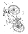
- the bicycle 10 basically includes a main frame 12, a rear chain stay 13, a front wheel 14 and a rear wheel 15.
- the main frame 12 is also equipped with a seat 16, a handlebar 17 and a front fork 18 that rotatably supports the front wheel 14 via a front dynamo hub 19 of the front wheel 14.
- the front wheel 14 is rotatably mounted to the front fork 18 by the front dynamo hub 19 in conventional manner.
- the main frame 12 basically includes a top tube 12a, a seat tube 12b, a down tube 12c and a head tube 12d.
- the rear wheel 15 is rotatably mounted to the rear chain stay 13, which in turn is coupled to the main frame 12 at the bottom bracket.
- the front fork 18 basically includes a steerer tube 18a that is rotatably mounted in the head tube 12d of the main frame 12 by the bicycle headset structure 11.
- the handlebar 17 is fixed to the front fork 18 for turning the front fork 18 and the front wheel 14 relative to the main frame 12.
- the cycle computer 31 includes a plurality of push buttons for operating the automatic shifting control.
- the cycle computer 31 is electrically coupled to the electric derailleurs 25 and 29 by the main electrical cable or cord 41, while the cycle computer 31 is electrically coupled to the electronic shifters 32 and 33 by the electrical shift cords 42 and 43, respectively.
- the bicycle headset structure 11 basically includes a stem bolt or steerer tube fastening member 50, a handlebar attachment member 51, a top tubular spacer member 52, a top steerer bearing set 53, a bottom steerer bearing set 54 and a bottom tubular spacer member 55.
- the bicycle headset structure 11 also preferably includes an internal headset wiring cable or cord 56 that is electrically coupled at one end to the main electrical cord 41 and splits into two sections at the other end for connection with front and rear devices or components.
- the bicycle headset structure 11 is mounted on the steerer tube 18a of the front fork 18 such that the steerer tube 18a can freely rotate within the head tube 12d.
- the handlebar 17 is fixed to the steerer tube 18a of the front fork 18 by the handlebar attachment member 51 in a conventional manner.
- the handlebar 17 is fixed to the front fork 18 for turning the front fork 18 and the front wheel 14 relative to the main frame 12.
- the top and bottom bearing sets 53 and 54 are installed with the top and bottom tubular spacer members 52 and 55 onto the upper and lower ends of the head tube 12d. Then, the steerer tube 18a is inserted into the head tube 12d such that the steerer tube 18a is rotatably supported in the head tube 12d by the top and bottom tubular spacer members 52 and 55. Next, the handlebar attachment member 51 is inserted onto the upper free end of the steerer tube 18a.
- the stem bolt 50 is inserted into the interior of the steerer tube 18a and adjusted to apply an axial force that pulls the steerer tube 18a upwardly and pushes the handlebar attachment member 51 downwardly to axially load the top and bottom bearing sets 53 and 54.
- the bicycle headset structure 11 is configured and arranged to exert a downward pressure or force on the handlebar attachment member 51, which in turn exert a downward pressure or axial force of the top and bottom bearing sets 53 and 54. This axial force on the bicycle headset structure 11 allows the user to apply an appropriate load to the top and bottom bearing sets 53 and 54.
- the handlebar attachment member 51 has a handlebar mounting portion 60 configured to secure the bicycle handlebar 17 thereto, an intermediate extension portion 61 and a steerer tube attachment portion 62 configured to secure the bicycle steerer tube 18a thereto.
- the handlebar mounting portion 60 is configured as a tube clamp that is constricted by a fastener 64, e.g. a bolt and a nut.
- the steerer tube attachment portion 62 is configured as a tube clamp that is constricted by a pair of fasteners 65, e.g. a pair of bolt and a pair of nut.
- the steerer tube attachment portion 62 has a radially contractible bore 66 that is dimensioned to receive the bicycle steerer tube 18a.
- the radially contractible bore 66 has a notch 67 that forms a portion of a wiring passage of the handlebar attachment member 51.
- the intermediate extension portion 61 is preferably at least partially hollow to form a wiring passage 68 of the handlebar attachment member 51.
- the wiring passage 68 has a first wiring aperture 69 that opens to the notch 67 of the steerer tube attachment portion 62, and a second wiring aperture 70 that opens to the bottom of the intermediate extension portion 61.
- the main electrical cord 41 is electrically connected to the internal headset wiring cord 56 through the second wiring aperture 70.
- the main electrical cord 41 and the internal headset wiring cord 56 can be a single integral cord, as needed and/or desired.
- the top and bottom tubular spacer members 52 and 55 are preferably each constructed as a one-piece, unitary member from a hard rigid material. More preferably, the top and bottom tubular spacer members 52 and 55 are constructed of a metallic material suitable for bicycles. The top and bottom tubular spacer members 52 and 55 are identical to each other, but the bottom tubular spacer member 55 is inverted relative to the top tubular spacer member 52. Thus, only the top tubular spacer member 52 will be discussed or illustrated in detail.
- the top tubular spacer member 52 has a first end portion 71 and a second end portion 72 with a central axial passageway 73 extending between the first and second end portions 71 and 72.
- the first end portion 71 has a first or upper end opening 74
- the second end portion 72 has a second or lower end opening 75.
- the central axial passageway 73 is dimensioned to receive the bicycle steerer tube 18a.
- the central axial passageway 73 has a generally cylindrical interior surface.
- a wiring channel 77 extends longitudinally between the first and second ends of the tubular spacer member 52.
- wiring channel 77 is an axially extending notch that is formed in the generally cylindrical interior surface of the central axial passageway 73.
- the wiring channel 77 is arranged to communicate with the notch 67 and the wiring passage 68 of the handlebar attachment member 51 when the handlebar attachment member 51 and the top tubular spacer member 52 are attached to the bicycle steerer tube 18a.
- the internal headset wiring cord 56 can pass from the handlebar attachment member 51 into the head tube 12d such that the internal headset wiring cord 56 will move with the steerer tube 18a.
- the stem bolt or steerer tube fastening member 50 is a relatively conventional structure that includes an expandable nut 50a dimensioned to engage an interior bore of the bicycle steerer tube 18a and a bolt 50b threadedly coupled to the expandable nut 50a.
- the bolt 50b including a head portion 50c that dimensioned to engage the steerer tube attachment portion 62 of the handlebar attachment member 51.
- the handlebar 17 has a pair of protective tubes 82 and 84 to protect the shift cords 42 and 43, respectively.
- the protective tubes 82 and 84 from the cycle computer 31 into openings 17a of the handlebar 17 to protect the shift cords 42 and 43, respectively.
- the shift cords 42 and 43 extend through the hollow interior of the handlebar ends, and then wrap around the free ends of the handlebar 17 so as to loop back on the outside of the handlebar 17 where they are connected to the electronic shifters 32 and 33.
- the handlebar 17 is provided with left and right handlebar grips 86 to hold the shift cords 42 and 43 in place.
- the hand grips 86 are identical. Thus, only one of the hand grips 86 will be discussed and illustrated in detail herein.
- the free ends of the handlebar 17 are provided with notches 17b for accommodating the wires 42 and 43.
- the shift cords 42 and 43 wrap around the free end of the handlebar 17, the shift cords 42 and 43 are located in the notches 17b.
- the grips 86 are preferably each provided with a longitudinally extending groove 87a such that the shift cords 42 and 43 can be disposed in the longitudinal grooves 87a when the grips 86 are installed on the free ends of the handlebar 17.
- the brake mounting portion 90 of the brake levers 92 have a similar type cross section to the grips 86 so that the shift cords 42 and 43 can pass between the mounting portions 90 of the brake levers 92 and the exterior surface of the handlebar 17.
- the front shifting unit 32 includes a pair of shifting push buttons for manually shifting the front derailleur 25 when the cycle computer 31 has been set by the rider to a manual mode.
- the front shifting unit 32 is electrically coupled to the cycle computer 31 by the electrical cord 42.
- the front shifting unit 32 inputs electrical commands to the cycle computer 31.
Applications Claiming Priority (2)
| Application Number | Priority Date | Filing Date | Title |
|---|---|---|---|
| US10/848,569 US6983949B2 (en) | 2004-05-19 | 2004-05-19 | Bicycle headset structure |
| EP04030301A EP1598263B1 (fr) | 2004-05-19 | 2004-12-21 | Structure de tube de direction de bicyclette |
Related Parent Applications (1)
| Application Number | Title | Priority Date | Filing Date |
|---|---|---|---|
| EP04030301.8 Division | 2004-12-21 |
Publications (3)
| Publication Number | Publication Date |
|---|---|
| EP2258613A2 true EP2258613A2 (fr) | 2010-12-08 |
| EP2258613A3 EP2258613A3 (fr) | 2011-01-19 |
| EP2258613B1 EP2258613B1 (fr) | 2012-07-04 |
Family
ID=34927888
Family Applications (2)
| Application Number | Title | Priority Date | Filing Date |
|---|---|---|---|
| EP04030301A Active EP1598263B1 (fr) | 2004-05-19 | 2004-12-21 | Structure de tube de direction de bicyclette |
| EP10176640A Active EP2258613B1 (fr) | 2004-05-19 | 2004-12-21 | Structure de tube de direction de bicyclette |
Family Applications Before (1)
| Application Number | Title | Priority Date | Filing Date |
|---|---|---|---|
| EP04030301A Active EP1598263B1 (fr) | 2004-05-19 | 2004-12-21 | Structure de tube de direction de bicyclette |
Country Status (6)
| Country | Link |
|---|---|
| US (1) | US6983949B2 (fr) |
| EP (2) | EP1598263B1 (fr) |
| JP (1) | JP4164080B2 (fr) |
| CN (1) | CN1699109B (fr) |
| DE (1) | DE602004029141D1 (fr) |
| TW (1) | TWI243131B (fr) |
Cited By (4)
| Publication number | Priority date | Publication date | Assignee | Title |
|---|---|---|---|---|
| DE202015004668U1 (de) * | 2015-07-02 | 2016-10-05 | Canyon Bicycles Gmbh | Fahrradgriff sowie Fahrradgriff-Lenker-System |
| TWI672241B (zh) * | 2018-03-07 | 2019-09-21 | 天心工業股份有限公司 | 自行車之車首及其豎管 |
| DE102018006153A1 (de) * | 2018-08-03 | 2020-02-06 | Hans-Jürgen Schlender | Steuersatz zur rotierbaren Lagerung eines Gabelschaftes |
| DE102020116139A1 (de) | 2020-06-18 | 2021-12-23 | Bayerische Motoren Werke Aktiengesellschaft | Vorderradführung für ein Neigefahrzeug sowie Neigefahrzeug |
Families Citing this family (57)
| Publication number | Priority date | Publication date | Assignee | Title |
|---|---|---|---|---|
| US7891687B2 (en) * | 2004-12-10 | 2011-02-22 | Magna Marque International Inc. | Method to conceal bicycle control cables within the handlebars, stem and frame |
| JP4286229B2 (ja) * | 2005-01-20 | 2009-06-24 | 株式会社シマノ | 自転車用ハンドルバー |
| JP2006244743A (ja) * | 2005-03-01 | 2006-09-14 | Shimano Inc | 自転車用配線接続構造 |
| TWM280973U (en) * | 2005-04-14 | 2005-11-21 | Tsang-Bing Chen | Bicycle frame with concealed gearshift cable |
| US7357403B2 (en) * | 2005-05-26 | 2008-04-15 | Vincenzo F Costa | Fork tree upper clamp |
| JP4164087B2 (ja) * | 2005-11-16 | 2008-10-08 | 株式会社シマノ | 自転車用ケーブル配索装置 |
| JP2007276549A (ja) * | 2006-04-03 | 2007-10-25 | Yamaha Motor Co Ltd | 自動二輪車 |
| CN201086794Y (zh) * | 2007-06-05 | 2008-07-16 | 深圳信隆实业股份有限公司 | 自行车控制线缆的安装结构 |
| ITMI20071352A1 (it) * | 2007-07-06 | 2009-01-07 | Campagnolo Srl | Kit di strumentazione di una bicicletta e bicicletta comprendente tale kit |
| WO2009146552A1 (fr) * | 2008-06-06 | 2009-12-10 | Société De Velo En Libre-Service | Ensemble fourche pour bicyclette |
| WO2009146551A1 (fr) * | 2008-06-06 | 2009-12-10 | Société de vélo en libre-service | Guidon pour bicyclette |
| US7854442B2 (en) * | 2008-08-29 | 2010-12-21 | Shimano Inc. | Bicycle wire holding arrangement |
| TW201114645A (en) * | 2009-10-20 | 2011-05-01 | shi-jie Zhang | Standpipe upper cover and manufacturing method thereof |
| NL2003770C2 (nl) * | 2009-11-09 | 2011-05-11 | Batavus Bv | Koppelstuk, alsmede werkwijze voor het vervaardigen van een fietsframe. |
| WO2012005610A2 (fr) * | 2010-07-09 | 2012-01-12 | Savy Man | Perfectionnements apportés à des jeux de direction de vélo ou s'y rapportant |
| AU2011288258A1 (en) * | 2010-08-12 | 2013-02-28 | Douglas Gregg Shadwell | Apparatus and method for routing bicycle control cables |
| ITVI20110152A1 (it) * | 2011-06-09 | 2012-12-10 | Wilier Triestina S P A | Forcella per biciclette e bicicletta comprendente tale forcella |
| US8684386B2 (en) * | 2011-07-04 | 2014-04-01 | Richard Peter Matthews | Head tube assembly for a bicycle with cable access routing in an open steerer configuration |
| GB2494714A (en) * | 2011-09-19 | 2013-03-20 | Karbon Kinetics Ltd | Internal cable routing at headset |
| US8408349B1 (en) | 2011-09-22 | 2013-04-02 | Faraday Bicycles, Inc. | Electric bicycle |
| US9403572B2 (en) * | 2013-07-01 | 2016-08-02 | Specialized Bicycle Components, Inc. | Bicycle frame with internal cable routing and method for making the same |
| US9615472B1 (en) | 2013-09-16 | 2017-04-04 | Craig Calfee | Preload anchoring mechanism with top cap adapted to receive subsystems, controls, indicators, and the like |
| EP3038891A4 (fr) * | 2013-09-16 | 2017-05-10 | Recreation Systems Inc. | Ensemble guidon et composants associés pour un cycle |
| US9010789B1 (en) * | 2014-01-10 | 2015-04-21 | Neco Technology Industry Co., Ltd. | Head parts assembly for a bicycle |
| US9446812B2 (en) * | 2014-03-17 | 2016-09-20 | Shimano Inc. | Bicycle stem |
| US9242692B2 (en) | 2014-03-17 | 2016-01-26 | Shimano Inc. | Compression ring and head parts |
| EP2923935A1 (fr) * | 2014-03-28 | 2015-09-30 | Neco Technology Industry Co., Ltd. | Ensemble de pièces de guidon et câble pour une bicyclette |
| US9457859B2 (en) * | 2014-04-17 | 2016-10-04 | Shimano Europe B.V. | Bicycle top cap |
| CN103963897A (zh) * | 2014-05-06 | 2014-08-06 | 王民海 | 一种前叉和车身的连接 |
| WO2015180756A1 (fr) * | 2014-05-27 | 2015-12-03 | Bmc Switzerland Ag | Fourche de bicyclette, cadre de bicyclette et bicyclette |
| US9056646B1 (en) | 2014-06-19 | 2015-06-16 | Specialized Bicycle Components, Inc. | Bicycle cable routing system |
| US9701293B2 (en) | 2014-06-19 | 2017-07-11 | Specialized Bicycle Components, Inc. | Bicycle cable routing system |
| US9174695B1 (en) * | 2014-07-10 | 2015-11-03 | Neco Technology Industry Co., Ltd. | Head parts assembly for a bicycle with a cable collecting device |
| EP2965981B1 (fr) * | 2014-07-11 | 2017-01-25 | Neco Technology Industry Co., Ltd. | Bicyclette |
| DE102014111917A1 (de) * | 2014-08-20 | 2016-02-25 | Gustav Magenwirth Gmbh & Co. Kg | Handbetätigte Gebereinheit |
| US9580130B2 (en) * | 2015-02-26 | 2017-02-28 | Ford Global Technologies, Llc | Bicycle with detachable head-tube subassembly |
| US10689056B2 (en) * | 2015-04-14 | 2020-06-23 | Matthew Hendey | Apparatus, systems, and methods for preventing migration of contaminants within tubing of a frame |
| US10150530B2 (en) * | 2015-05-21 | 2018-12-11 | Trek Bicycle Corporation | Rigid frame with high-compliance seat tube and internal cable routing |
| TWI568622B (zh) * | 2015-11-13 | 2017-02-01 | 溫芫鋐 | 自行車導線配線系統 |
| CN106364615A (zh) * | 2016-09-30 | 2017-02-01 | 北京野兽科技有限公司 | 一种内走线自行车车架及用于该车架的走线方法 |
| US10812645B2 (en) * | 2017-05-18 | 2020-10-20 | Carla Marie Montez | Handlebar systems and method |
| US10858061B2 (en) * | 2017-05-18 | 2020-12-08 | Carla Marie Montez | Integrated handlebar system and method |
| CH714098A2 (de) * | 2017-08-29 | 2019-03-15 | Mystromer Ag | Hohlzylindrisches Bauteil sowie Vorbau für ein Fahrrad und Fahrrad. |
| AT520501B1 (de) * | 2017-10-06 | 2019-09-15 | Airstreeem Com Gmbh | Anordnung aus einem Rahmen für ein Fahrrad und einem Fahrradlenker |
| CN108482556B (zh) * | 2018-04-10 | 2020-02-18 | 常州洪记两轮智能交通工具有限公司 | 一种单车内走线系统 |
| US10953948B2 (en) * | 2018-05-31 | 2021-03-23 | Tien Hsin Industries Co., Ltd. | Cable routing system of bicycle and stem thereof |
| DE102019002207B4 (de) | 2019-03-27 | 2020-11-26 | Hans-Jürgen Schlender | Kabelführung zur lösbaren Aufnahme und Fixierung von wenigstens einem Kabel an einem Lenker eines Zweirades |
| DE202019104749U1 (de) * | 2019-08-29 | 2019-09-11 | Scott Sports Sa | Lenkervorbau mit integrierter Zugführung |
| NL2023744B1 (en) * | 2019-09-02 | 2021-05-12 | Koninklijke Gazelle N V | Bicycle |
| NL2024186B1 (nl) * | 2019-11-07 | 2021-09-29 | Vanmoof Bv | Rijwielstuur |
| WO2021209937A1 (fr) * | 2020-04-17 | 2021-10-21 | Calamus Electric Private Limited | Ensemble guidon pour une bicyclette |
| US11794848B2 (en) | 2020-12-14 | 2023-10-24 | Sram, Llc | Hydraulic brake control device with handlebar proximal hose attachment |
| US11912372B2 (en) | 2020-12-14 | 2024-02-27 | Sram, Llc | Hydraulic brake control device with handlebar proximal hose attachment |
| TWM621827U (zh) | 2021-08-27 | 2022-01-01 | 信隆車料工業股份有限公司 | 自行車用纜線定位裝置 |
| AT525529A1 (de) * | 2021-09-30 | 2023-04-15 | Simplon Fahrrad Gmbh | Fahrrad mit einem Fahrradrahmen und einer Vorderradgabel |
| DE202022100922U1 (de) | 2022-02-17 | 2022-02-23 | Scott Sports Sa | Anordnung zum Verbinden eines Fahrradlenkers mit einer Fahrradgabel |
| CN115320757A (zh) * | 2022-07-15 | 2022-11-11 | 拓肯兴业股份有限公司 | 车用线材的配线装置 |
Family Cites Families (41)
| Publication number | Priority date | Publication date | Assignee | Title |
|---|---|---|---|---|
| GB274643A (en) * | 1926-07-22 | 1927-07-28 | A M A C Ltd | Improvements in twisting handlebar controls for motor cycles and the like |
| JPS5655108Y2 (fr) | 1977-07-12 | 1981-12-22 | ||
| JPS5831748Y2 (ja) | 1978-07-12 | 1983-07-14 | 株式会社シマノ | 自転車用ハンドルステムの固定構造 |
| US4435983A (en) | 1980-11-22 | 1984-03-13 | Shimano Industrial Company Limited | Handle stem for a bicycle |
| US4489307A (en) | 1981-05-23 | 1984-12-18 | Shimano Industrial Company Limited | Handle stem for a bicycle |
| JPS6240868U (fr) | 1985-08-30 | 1987-03-11 | ||
| US4653768A (en) * | 1986-03-26 | 1987-03-31 | Keys Kenney L | Free spinning handlebar-brake cable connection |
| US4770435A (en) * | 1987-06-29 | 1988-09-13 | North America Tradimpex Cycles, Inc. | Freestyle bicycle construction |
| US4966047A (en) * | 1987-12-07 | 1990-10-30 | Alwin Krauer | Handlebar-mounted cable control |
| US4881750A (en) | 1989-02-06 | 1989-11-21 | Hartmann Dirck T | ATB shock absorber |
| WO1990013470A1 (fr) * | 1989-05-03 | 1990-11-15 | Ueli Eser | Frein hydraulique sur jante pour bicyclette |
| DE3934960A1 (de) | 1989-10-20 | 1991-04-25 | Stabilus Gmbh | Ausloesevorrichtung fuer pneumatische und hydropneumatische hoehenverstelleinrichtungen |
| US5095770B1 (en) | 1990-09-28 | 2000-01-25 | Homer J Radar | Steering bearing assembly for wheeled vehicle |
| JP2546159Y2 (ja) | 1991-11-05 | 1997-08-27 | 株式会社シマノ | 自転車用ヘッドパーツ |
| US5248159A (en) | 1992-02-18 | 1993-09-28 | Moore James D | Lightweight self-adjusting semihydraulic suspension system |
| US5305654A (en) | 1993-06-07 | 1994-04-26 | Durham Roger O | Headset for bicycles with external forks |
| US5319993A (en) | 1993-09-02 | 1994-06-14 | Tien Hsin Industries Co., Ltd. | Steering bearing assembly for a bicycle |
| US5496126A (en) | 1994-12-20 | 1996-03-05 | Lin; Wen-Hwa | Bicycle front fork mounting structure |
| US6167780B1 (en) | 1995-01-24 | 2001-01-02 | Sheng-Luen Chen | Device for making micro adjusting the steering bearing of bicycle |
| JPH08290793A (ja) | 1995-02-21 | 1996-11-05 | Marui:Kk | 自転車用ヘッドセットの玉軸受及びこれの取付部の構造 |
| US6145637A (en) | 1995-02-23 | 2000-11-14 | Hopey; Timothy C. | Steering damper in and for vehicles |
| US5647684A (en) | 1995-05-16 | 1997-07-15 | Chen; Chia-Ching | Two-step and toothless bicycle head shaft bowl set |
| US5826898A (en) | 1995-12-04 | 1998-10-27 | Fortier; Robert L. | Modular steering headset for use on a bicycle |
| US5927740A (en) | 1996-08-14 | 1999-07-27 | Hopey; Timothy C. | Steering damper in and for vehicles |
| US5800071A (en) | 1996-12-05 | 1998-09-01 | Chi; Yi-Chen | Journal for a head tube of a bicycle |
| US6050583A (en) | 1997-01-13 | 2000-04-18 | Bohn; David D. | Electronically controlled bicycle suspension apparatus |
| US5971116A (en) | 1997-03-13 | 1999-10-26 | Cannondale Corporation | Electronic suspension system for a wheeled vehicle |
| US6122991A (en) * | 1998-02-10 | 2000-09-26 | Clarkson; Douglas Dean | Handlebar assembly for vehicles and method for making the same |
| US5918895A (en) | 1998-05-28 | 1999-07-06 | Chi; Yi-Chen | Headset assembly for a bicycle |
| US6019017A (en) | 1999-03-15 | 2000-02-01 | Lin; King-Chen | Upper headset assembly for a bicycle |
| US6220398B1 (en) * | 1999-11-01 | 2001-04-24 | Wu Chin-Chang | Brake cable positioning assembly for an inner swivel connector of a free style bicycle |
| US6543799B2 (en) | 2000-01-13 | 2003-04-08 | Shimano Inc. | Bicycle suspension |
| US6310260B1 (en) * | 2000-03-15 | 2001-10-30 | Union Carbide Chemicals & Plastics Technology Corporation | Separation processes |
| IT1320338B1 (it) * | 2000-05-09 | 2003-11-26 | Campagnolo Srl | Gruppo di sterzo per una bicicletta. |
| JP3476746B2 (ja) | 2000-05-29 | 2003-12-10 | 株式会社マルイ | 自転車用ホークステムの支持構造 |
| US6584872B1 (en) * | 2000-10-31 | 2003-07-01 | Shimano Inc. | Bicycle handle mounting member |
| US6343806B1 (en) | 2001-03-29 | 2002-02-05 | Qun-Yuan Lee | Bicycle head set assembly |
| US6711966B2 (en) | 2002-01-25 | 2004-03-30 | Louis Chuang | Accessory-mounting device for a bicycle |
| JP3635306B2 (ja) * | 2002-06-11 | 2005-04-06 | 株式会社キャットアイ | ハンドルステムおよび速度表示装置 |
| DE102004014467A1 (de) * | 2003-03-26 | 2004-11-18 | Schmider, John, Thornhill | Ein Fahrrad mit intern geführten Steuerkabeln |
| US7080848B2 (en) * | 2003-09-17 | 2006-07-25 | Shimano Inc. | Bicycle head cap unit |
-
2004
- 2004-05-19 US US10/848,569 patent/US6983949B2/en active Active
- 2004-11-10 TW TW093134330A patent/TWI243131B/zh not_active IP Right Cessation
- 2004-12-21 EP EP04030301A patent/EP1598263B1/fr active Active
- 2004-12-21 EP EP10176640A patent/EP2258613B1/fr active Active
- 2004-12-21 DE DE602004029141T patent/DE602004029141D1/de active Active
- 2004-12-30 CN CN2004101037090A patent/CN1699109B/zh active Active
-
2005
- 2005-05-10 JP JP2005136891A patent/JP4164080B2/ja active Active
Non-Patent Citations (1)
| Title |
|---|
| None |
Cited By (5)
| Publication number | Priority date | Publication date | Assignee | Title |
|---|---|---|---|---|
| DE202015004668U1 (de) * | 2015-07-02 | 2016-10-05 | Canyon Bicycles Gmbh | Fahrradgriff sowie Fahrradgriff-Lenker-System |
| TWI672241B (zh) * | 2018-03-07 | 2019-09-21 | 天心工業股份有限公司 | 自行車之車首及其豎管 |
| DE102018006153A1 (de) * | 2018-08-03 | 2020-02-06 | Hans-Jürgen Schlender | Steuersatz zur rotierbaren Lagerung eines Gabelschaftes |
| DE102018006153B4 (de) * | 2018-08-03 | 2021-05-06 | Hans-Jürgen Schlender | Steuersatz zur rotierbaren Lagerung eines Gabelschaftes |
| DE102020116139A1 (de) | 2020-06-18 | 2021-12-23 | Bayerische Motoren Werke Aktiengesellschaft | Vorderradführung für ein Neigefahrzeug sowie Neigefahrzeug |
Also Published As
| Publication number | Publication date |
|---|---|
| EP1598263B1 (fr) | 2010-09-15 |
| US6983949B2 (en) | 2006-01-10 |
| EP2258613B1 (fr) | 2012-07-04 |
| US20050258617A1 (en) | 2005-11-24 |
| EP1598263A2 (fr) | 2005-11-23 |
| CN1699109A (zh) | 2005-11-23 |
| DE602004029141D1 (de) | 2010-10-28 |
| JP4164080B2 (ja) | 2008-10-08 |
| EP1598263A3 (fr) | 2006-10-04 |
| TWI243131B (en) | 2005-11-11 |
| EP2258613A3 (fr) | 2011-01-19 |
| JP2005329938A (ja) | 2005-12-02 |
| TW200538345A (en) | 2005-12-01 |
| CN1699109B (zh) | 2011-08-03 |
Similar Documents
| Publication | Publication Date | Title |
|---|---|---|
| EP2258613B1 (fr) | Structure de tube de direction de bicyclette | |
| US7093844B2 (en) | Bicycle headset structure | |
| EP1787899B1 (fr) | Dispositif d'installation de cable pour bicyclettes | |
| US7080848B2 (en) | Bicycle head cap unit | |
| EP1911668B1 (fr) | Ensemble guidon de bicyclette et dispositif d'actionnement d'un frein de bicyclette | |
| EP1816062B1 (fr) | Dispositif de commande des vitesses de bicyclette | |
| US7854442B2 (en) | Bicycle wire holding arrangement | |
| EP1816066A1 (fr) | Actionneur pour transmission de bicyclette commandé électriquement | |
| US7503547B2 (en) | Bicycle electric cable tensioning assembly | |
| EP1529725B1 (fr) | Structure de direction expansible de bicyclette | |
| EP0035372A2 (fr) | Guidons de bicyclette |
Legal Events
| Date | Code | Title | Description |
|---|---|---|---|
| PUAI | Public reference made under article 153(3) epc to a published international application that has entered the european phase |
Free format text: ORIGINAL CODE: 0009012 |
|
| AC | Divisional application: reference to earlier application |
Ref document number: 1598263 Country of ref document: EP Kind code of ref document: P |
|
| AK | Designated contracting states |
Kind code of ref document: A2 Designated state(s): DE NL |
|
| PUAL | Search report despatched |
Free format text: ORIGINAL CODE: 0009013 |
|
| AK | Designated contracting states |
Kind code of ref document: A3 Designated state(s): DE NL |
|
| RIN1 | Information on inventor provided before grant (corrected) |
Inventor name: UENO, KOKEN Inventor name: MIYOSHI, HIROYUKI |
|
| 17P | Request for examination filed |
Effective date: 20110719 |
|
| REG | Reference to a national code |
Ref country code: DE Ref legal event code: R079 Ref document number: 602004038475 Country of ref document: DE Free format text: PREVIOUS MAIN CLASS: B62K0021120000 Ipc: B62M0025020000 |
|
| RIC1 | Information provided on ipc code assigned before grant |
Ipc: B62M 25/02 20060101AFI20111108BHEP Ipc: B62K 21/12 20060101ALI20111108BHEP Ipc: B62K 21/06 20060101ALN20111108BHEP Ipc: B62J 6/18 20060101ALN20111108BHEP |
|
| GRAP | Despatch of communication of intention to grant a patent |
Free format text: ORIGINAL CODE: EPIDOSNIGR1 |
|
| GRAS | Grant fee paid |
Free format text: ORIGINAL CODE: EPIDOSNIGR3 |
|
| GRAA | (expected) grant |
Free format text: ORIGINAL CODE: 0009210 |
|
| AC | Divisional application: reference to earlier application |
Ref document number: 1598263 Country of ref document: EP Kind code of ref document: P |
|
| AK | Designated contracting states |
Kind code of ref document: B1 Designated state(s): DE NL |
|
| REG | Reference to a national code |
Ref country code: DE Ref legal event code: R096 Ref document number: 602004038475 Country of ref document: DE Effective date: 20120830 |
|
| REG | Reference to a national code |
Ref country code: NL Ref legal event code: T3 |
|
| PLBE | No opposition filed within time limit |
Free format text: ORIGINAL CODE: 0009261 |
|
| STAA | Information on the status of an ep patent application or granted ep patent |
Free format text: STATUS: NO OPPOSITION FILED WITHIN TIME LIMIT |
|
| 26N | No opposition filed |
Effective date: 20130405 |
|
| REG | Reference to a national code |
Ref country code: DE Ref legal event code: R097 Ref document number: 602004038475 Country of ref document: DE Effective date: 20130405 |
|
| PGFP | Annual fee paid to national office [announced via postgrant information from national office to epo] |
Ref country code: NL Payment date: 20141108 Year of fee payment: 11 |
|
| REG | Reference to a national code |
Ref country code: NL Ref legal event code: MM Effective date: 20160101 |
|
| PG25 | Lapsed in a contracting state [announced via postgrant information from national office to epo] |
Ref country code: NL Free format text: LAPSE BECAUSE OF NON-PAYMENT OF DUE FEES Effective date: 20160101 |
|
| REG | Reference to a national code |
Ref country code: DE Ref legal event code: R082 Ref document number: 602004038475 Country of ref document: DE Representative=s name: SONNENBERG HARRISON PARTNERSCHAFT MBB, DE Ref country code: DE Ref legal event code: R082 Ref document number: 602004038475 Country of ref document: DE Representative=s name: SONNENBERG HARRISON PARTNERSCHAFT MBB PATENT- , DE |
|
| P01 | Opt-out of the competence of the unified patent court (upc) registered |
Effective date: 20230421 |
|
| PGFP | Annual fee paid to national office [announced via postgrant information from national office to epo] |
Ref country code: DE Payment date: 20231031 Year of fee payment: 20 |