EP2258584B1 - Rückenlehne für einen Fahrzeugsitz - Google Patents
Rückenlehne für einen Fahrzeugsitz Download PDFInfo
- Publication number
- EP2258584B1 EP2258584B1 EP10004838.8A EP10004838A EP2258584B1 EP 2258584 B1 EP2258584 B1 EP 2258584B1 EP 10004838 A EP10004838 A EP 10004838A EP 2258584 B1 EP2258584 B1 EP 2258584B1
- Authority
- EP
- European Patent Office
- Prior art keywords
- backrest
- blowers
- arms
- air
- blower
- Prior art date
- Legal status (The legal status is an assumption and is not a legal conclusion. Google has not performed a legal analysis and makes no representation as to the accuracy of the status listed.)
- Active
Links
Images



Classifications
-
- B—PERFORMING OPERATIONS; TRANSPORTING
- B60—VEHICLES IN GENERAL
- B60N—SEATS SPECIALLY ADAPTED FOR VEHICLES; VEHICLE PASSENGER ACCOMMODATION NOT OTHERWISE PROVIDED FOR
- B60N2/00—Seats specially adapted for vehicles; Arrangement or mounting of seats in vehicles
- B60N2/56—Heating or ventilating devices
- B60N2/5607—Heating or ventilating devices characterised by convection
- B60N2/5621—Heating or ventilating devices characterised by convection by air
- B60N2/5671—Heating or ventilating devices characterised by convection by air forming a windbreak, e.g. warm air blown on the neck of the passenger of an open vehicle
Definitions
- the invention relates to a backrest for a vehicle seat of a motor vehicle.
- neck warmer which are particularly applied to convertible vehicle seats, are well known in the art. Reference is made, for example, to the DE 10 2006 031 260 A1 , the DE 10 2004 024 261 B3 , the DE 196 54 370 C1 or the DE 10 2004 060 460 A1 ,
- a neck warmer consists of an air duct, at the beginning of which a blower sits, which draws air through suction openings (slots) in the backrest and via a PTC heater to an air outflow opening, which is usually arranged on the upper narrow side of the backrest. It is also known to arrange the air outlet openings in the shoulder region on the front side of the backrest.
- Object of the present invention is to remedy this situation and show a neck warmer that can be easily installed in the existing space of backrests of vehicle seats.
- the solution is based on the already from the DE 10 2004 043 923 A1 known knowledge that not a fan with a suction port, which must be relatively large due to the required volumes and pressures, is provided, but that the air duct has at least two arms in its entrance area, which then combine to form a single air outlet channel. This makes it possible to place the air intake openings where they can be arranged most meaningfully. These arms can be adapted to the conditions in the interior of the backrest, so that the backrest itself does not have to be increased in strength. In each arm a fan is arranged, resulting in a small space requirement.
- the fans are formed in the air intake at the beginning of the two arms as a radial fan, which in the
- Air intake openings are arranged flush with the contour of the air duct.
- Radial fans are small blowers.
- radial fans have a small overall depth, so that the integrated into the backrest device for supplying an air flow can be performed with a total of low overall depth, with the advantage that the backrest itself does not have to be increased in thickness.
- radial fans generate a relatively high air pressure, so that the fan speeds can be reduced. This has the advantage that the fans run relatively quietly, so that they are practically not heard in the state of the vehicle when wind noise falls away.
- a neck warmer is created, which is physically small and can be easily installed without increasing the volume of a vehicle seat back. Its effectiveness is not limited thereby.
- the air duct runs substantially in a plane parallel to the front and the back of the backrest.
- the thickness of the backrest can be further reduced.
- this runs in the from the DE 10 2004 043 923 A1 known vehicle seat of the air duct substantially in an approximately horizontally oriented plane across the entire depth extent of the headrest, ie in a plane which is perpendicular to the front and the back of the backrest.
- the development according to claim 4 has the advantage that the air flow in quantity and pressure can be adjusted easier when the blower can work with different power. It is also possible in this case to allow only one fan to run in certain vehicle states and only to drive both at higher requirements (for example maximum power).
- the development according to claim 5 reduces the space for the heating element.
- FIG. 1 schematically shows a backrest 1 of a motor vehicle seat. At the upper end of the backrest, a headrest 2 is arranged adjustable in height.
- a neck warmer 3 is installed in the backrest. It consists of an air duct 4, the suction side has two arms 5, 6, which serve as air intake ducts. In the context of the invention, it is possible to provide more than two arms, in particular, if the structural conditions within the backrest make this appear reasonable and / or necessary.
- the two arms 5 and 6 unite in the region 7 to form a common channel, which opens into an outlet opening 8 in the upper region of the backrest.
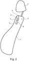
- FIG. 2 is a side view of the arrangement according to FIG. 1 shown.
- the outlet opening 8 is arranged in the front upper region of the backrest such that the outflowing air is directed towards the shoulder / neck / head region of a person sitting on the seat.
- the air is sucked in via air intake openings 9 and 10 at the beginning of the two arms 5 and 6 via a respective non-illustrated radial fan, which is arranged in the air intake openings 9 and 10 flush with the contour of the air duct 4.
- FIG. 3a shows a front view of the backrest 1 with built neck warmer 3. Here it is visible that in the air flow direction behind each radial fan in each arm 5, 6, a heating element 11, 12 is arranged.
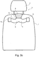
- a single heating element 13 can be arranged in the air flow direction behind the area 7, such as FIG. 3b shows.
- FIG. 4 is a schematic view of the Nackenizirs 3 shown in the disassembled state.
- the air duct 4 of the Nackenoasars 3 can be made of two plastic half-shells, which are connected to each other separable or inseparable after installation of the required elements (blower, heating element).
- the heating element / elements as plug-in cassettes in the air duct 4 of the neck warmer 3.
- the housing can be made in one piece, although it is ensured that each fan at the beginning of the arms 5, 6 can be installed through the air intake openings 9, 10.
- the air duct 4 of the neck warmer 3 is fastened via suitable fastening elements within the backrest 1.
- the air intake openings 9, 10 of the arms 5, 6 can open inside the backrest 1, but they can also open to the outside on the back of the backrest. In this case they are preferred with Provided ventilation grille. It is also conceivable to make these ventilation grids lockable.
- a neck warmer is created, which is physically small and can be easily installed without increasing the volume of a vehicle seat back. Its effectiveness is not limited thereby.
Landscapes
- Engineering & Computer Science (AREA)
- Aviation & Aerospace Engineering (AREA)
- Transportation (AREA)
- Mechanical Engineering (AREA)
- Chair Legs, Seat Parts, And Backrests (AREA)
- Air-Conditioning For Vehicles (AREA)
Description
- Die Erfindung bezieht sich auf eine Rückenlehne für einen Fahrzeugsitz eines Kraftfahrzeuges.
- Sogenannte Nackenwärmer, die insbesondere bei Cabrio-Fahrzeugsitzen angewandt werden, sind im Stand der Technik allgemein bekannt. Verwiesen wird beispielsweise auf die
DE 10 2006 031 260 A1 , dieDE 10 2004 024 261 B3 , dieDE 196 54 370 C1 oder dieDE 10 2004 060 460 A1 . - Um die mit Nackenwärmem ausgerüsteten Fahrzeugsitze wie nicht ausgerüstete Sitze verstellbar zu erhalten, ist man dazu übergegangen, den Nackenwärmer in die Rückenlehne des Fahrzeugsitzes einzubauen.
- Allgemein besteht ein Nackenwärmer aus einem Luftführungskanal, an dessen Beginn ein Gebläse sitzt, das Luft durch Ansaugöffnungen (Schlitze) in der Rückenlehne ansaugt und über einen PTC-Heizer zu einer Luftausströmöffnung führt, die in der Regel an der oberen Schmalseite der Rückenlehne angeordnet ist. Auch ist es bekannt, die Luftaustrittsöffnungen im Schulterbereich auf der Vorderseite der Rückenlehne anzuordnen.
- Aus der
DE 10 2004 043 923 A1 ist ein Fahrzeugsitz mit einem Nackenwärmer bekannt, dessen Luftführungskanal eingangsseitig in zwei Arme aufgeteilt ist, wobei im Eingangsbereich jedes Arms ein Gebläse angeordnet ist. - Allen bisher vorgeschlagenen Lösungen gemeinsam ist der Nachteil, dass sie einigen Bauraum beanspruchen, der in den Rückenlehnen nicht ohne weiteres vorhanden ist. Deshalb werden in der Regel die Rückenlehnen in ihrer Dicke größer.
- Aufgabe der vorliegenden Erfindung ist es, hier Abhilfe zu schaffen und einen Nackenwärmer aufzuzeigen, der sich problemlos in bestehenden Raum von Rückenlehnen von Fahrzeugsitzen einbauen lässt.
- Diese Aufgabe wird erfindungsgemäß durch die Merkmale des ersten Anspruchs gelöst.
- Die Lösung baut auf der bereits aus der
DE 10 2004 043 923 A1 bekannten Erkenntnis auf, dass nicht ein Gebläse mit einer Ansaugöffnung, das aufgrund der geforderten Volumina und Drücke relativ großbauend sein muss, vorgesehen wird, sondern dass der Luftführungskanal in seinem Eingangsbereich mindestens zwei Arme aufweist, die sich dann zu einem einzigen Luftaustrittskanal vereinen. Damit ist es möglich, die Luftansaugöffnungen dorthin zu legen, wo sie am sinnvollsten angeordnet werden können. Auch können diese Arme den Gegebenheiten im Innenraum der Rückenlehne angepasst werden, so dass die Rückenlehne selbst nicht in ihrer Stärke vergrößert werden muss. In jedem Arm ist ein Gebläse angeordnet, wodurch sich ein geringer Bauraumbedarf ergibt. - Erfindungsgemäß sind die Gebläse in den Luftansaugöffnungen am Beginn der beiden Arme als Radialgebläse ausgebildet, die in den
- Luftansaugöffnungen bündig mit der Kontur des Luftführungskanals angeordnet sind. Radialgebläse sind kleinbauende Gebläse. Insbesondere weisen Radialgebläse eine geringe Bautiefe auf, so dass die in die Rückenlehne integrierte Vorrichtung zum Zuführen eines Luftstroms mit einer insgesamt geringen Bautiefe ausgeführt werden kann, mit dem Vorteil, dass die Rückenlehne selbst nicht in ihrer Dicke vergrößert werden muss. Außerdem erzeugen Radialgebläse einen relativ hohen Luftdruck, so dass die Gebläsedrehzahlen herabgesetzt werden können. Dies hat den Vorteil, dass die Gebläse relativ leise laufen, so dass sie im Stand des Fahrzeugs, wenn Windgeräusche fortfallen, praktisch nicht zu hören sind.
- Durch die Erfindung wird ein Nackenwärmer geschaffen, der kleinbauend ist und sich ohne Vergrößerung des Volumens einer Fahrzeugrückenlehne in diese problemlos einbauen lässt. Seine Wirksamkeit wird dadurch nicht eingeschränkt.
- In vorteilhafter Ausgestaltung der Erfindung verläuft der Luftführungskanal im Wesentlichen in einer Ebene parallel zur Vorder- und zur Rückseite der Rückenlehne. Durch diese Anordnung kann die Dicke der Rückenlehne weiter verringert werden. Im Unterschied hierzu verläuft bei dem aus der
DE 10 2004 043 923 A1 bekannte Fahrzeugsitz der Luftführungskanal im Wesentlichen in einer etwa horizontal ausgerichteten Ebene quer durch die gesamte Tiefenerstreckung der Kopfstütze, also in einer Ebene, die senkrecht zur Vorder- und zur Rückseite der Rückenlehne verläuft. - Die weiteren Unteransprüche 3 bis 10 stellen bevorzugte Ausführungsformen der Erfindung dar.
- Durch die Weiterbildung nach Anspruch 3 wird die Herstellung vereinfacht, wenn es sich um Gleichteile handelt. Auch wird die Ersatzteilhaltung dadurch einfacher.
- Die Weiterbildung nach Anspruch 4 hat den Vorteil, dass sich der Luftstrom in Menge und Druck einfacher einstellen lässt, wenn die Gebläse mit unterschiedlicher Leistung arbeiten können. Auch ist es hierbei möglich, bei bestimmten Fahrzeugzuständen nur ein Gebläse laufen zu lassen und erst bei höheren Anforderungen (z.B. Maximalleistung) beide anzutreiben.
- Die Weiterbildung nach Anspruch 5 verkleinert den Bauraum für das Heizelement.
- Die Weiterbildung nach Anspruch 6 und 7 bietet sich insbesondere dann an, wenn Gebläse unterschiedlicher Leistungen verwendet werden, die dann entsprechend der geforderten Luftmenge und des geforderten Luftdruckes gesteuert werden.
- Die Weiterbildung nach den Ansprüchen 8 bis 10 beschreibt - je nach Einbauverhältnissen - unterschiedliche Anordnungen für die Ansaugöffnung innerhalb der Rückenlehne oder zum Ansaugen von Luft außerhalb der Rückenlehne.
- Im Folgenden wird die Erfindung anhand eines bevorzugten Ausführungsbeispiels schematisch dargestellt. Es stellen dar:
- Figur 1
- Eine schematisierte Ansicht einer Rückenlehne eines Fahrzeugsitzes mit eingebautem Nackenwärmer;
- Figur 2
- eine Seitenansicht der Anordnung gemäß
Figur 1 ; - Figur 3a
- alternative Ausgestaltungen des Nackenwärmers nach
Figur 1 ; - Figur 4
- eine perspektivische Ansicht des Gehäuses des Nackenwärmers.
-
Figur 1 stellt schematisiert eine Rückenlehne 1 eines Kraftfahrzeugsitzes dar. Am oberen Ende der Rückenlehne ist eine Kopfstütze 2 höhenverstellbar angeordnet. - Im oberen Bereich der Rückenlehne 1 ist ein Nackenwärmer 3 in die Rückenlehne eingebaut. Er besteht aus einem Luftführungskanal 4, der ansaugseitig zwei Arme 5, 6 aufweist, die als Luftansaugkanäle dienen. Im Rahmen der Erfindung ist es möglich, mehr als zwei Arme vorzusehen, insbesondere, wenn die baulichen Gegebenheiten innerhalb der Rückenlehne diese sinnvoll und/oder notwendig erscheinen lassen.
- Die beiden Arme 5 und 6 vereinigen sich im Bereich 7 zu einem gemeinsamen Kanal, der in eine Austrittsöffnung 8 im oberen Bereich der Rückenlehne mündet.
- In
Figur 2 ist eine Seitenansicht der Anordnung nachFigur 1 dargestellt. Hier sieht man deutlich, dass die Austrittsöffnung 8 im vorderen oberen Bereich der Rückenlehne derart angeordnet ist, dass die ausströmende Luft in Richtung auf den Schulter-/Nacken-/Kopfbereich einer auf den Sitz sitzenden Person gerichtet ist. - Angesaugt wird die Luft über Luftansaugöffnungen 9 und 10 am Beginn der beiden Arme 5 und 6 über je ein nicht näher dargestelltes Radialgebläse, das in den Luftansaugöffnungen 9 und 10 bündig mit der Kontur des Luftführungskanals 4 angeordnet ist.
-
Figur 3a zeigt eine Vorderansicht der Rückenlehne 1 mit eingebautem Nackenwärmer 3. Hier ist sichtbar, dass in Luftströmungsrichtung hinter jedem Radialgebläse in jedem Arm 5, 6 ein Heizelement 11, 12 angeordnet ist. - Alternativ hierzu kann ein einziges Heizelement 13 in Luftströmungsrichtung hinter dem Bereich 7 angeordnet werden, wie
Figur 3b zeigt. - In
Figur 4 ist eine schematisierte Ansicht des Nackenwärmers 3 im ausgebauten Zustand dargestellt. Der Luftführungskanal 4 des Nackenwärmers 3 kann aus zwei Kunststoffhalbschalen hergestellt werden, die nach Einbau der benötigten Elemente (Gebläse, Heizelement) miteinander trennbar oder untrennbar verbunden werden. Alternativ ist es möglich, das Heizelement/die Heizelemente als Einschubkassetten in den Luftführungskanal 4 des Nackenwärmers 3 vorzusehen. In diesem Fall kann das Gehäuse einteilig ausgeführt werden, wenn auch dafür Sorge getragen wird, dass jedes Gebläse zu Beginn der Arme 5, 6 durch die Luftansaugöffnungen 9, 10 eingebaut werden kann. - Der Luftführungskanal 4 des Nackenwärmers 3 wird über geeignete Befestigungselemente innerhalb der Rückenlehne 1 befestigt.
- Die Luftansaugöffnungen 9, 10 der Arme 5, 6 können innerhalb der Rückenlehne 1 münden, sie können aber auch auf der Rückseite der Rückenlehne ins Freie münden. In diesem Fall sind sie bevorzugt mit Lüftungsgitter versehen. Auch ist es denkbar, diese Lüftungsgitter verschließbar auszugestalten.
- Zur Steuerung des Heizelementes/der Heizelemente und der Gebläse wird in der Regel ein Steuergerät vorgesehen. Hierbei ist es denkbar, die Gebläse gemeinsam gleichzeitig, nacheinander oder einzeln anzusteuern.
- Durch die Erfindung wird ein Nackenwärmer geschaffen, der kleinbauend ist und sich ohne Vergrößerung des Volumens einer Fahrzeugrückenlehne in diese problemlos einbauen zu lassen. Seine Wirksamkeit wird dadurch nicht eingeschränkt.
Claims (9)
- Rückenlehne (1) für einen Fahrzeugsitz eines Kraftfahrzeuges, insbesondere eines Cabriolets, mit einer in der Rückenlehne (1) integrierten Vorrichtung zum Zuführen eines Luftstroms, insbesondere eines Warmluftstromes, in den Schulter-, Nacken- und/oder Kopfbereiche eines Sitzenden, bestehend aus einem Luftführungskanal (4), in den ein Gebläse und ein Heizelement (11, 12, 13) eingebaut ist und dessen Austrittsöffnung (8) im Bereich des oberen Teils der Rückenlehne (1) angeordnet ist, wobei der Luftführungskanal (4) eingangsseitig in mindestens zwei Arme (5, 6) aufgeteilt und in jedem Arm (5, 6) ein Gebläse angeordnet ist, wobei die Gebläse in den Eingangsbereichen der Arme (5, 6) in Luftansaugöffnungen (9, 10) bündig mit der Kontur des Luftführungskanals (4) angeordnet sind, dadurch gekennzeichnet, dass die Gebläse als Radialgebläse ausgebildet sind.
- Rückenlehne nach Anspruch 1, dadurch gekennzeichnet, dass die Gebläse gleiche Abmessungen und gleiche Leistungen aufweisen.
- Rückenlehne nach einem der vorangegangenen Ansprüche,
dadurch gekennzeichnet, dass die Gebläse gleiche Abmessungen, aber unterschiedliche Leistungen aufweisen. - Rückenlehne nach einem der vorangegangenen Ansprüche,
dadurch gekennzeichnet, dass in jedem Arm (5, 6) in Strömungsrichtung hinter dem Gebläse ein Heizelement (11, 12) angeordnet ist. - Rückenlehne nach einem der vorangegangenen Ansprüche,
dadurch gekennzeichnet, dass jedes Gebläse separat ansteuerbar ist. - Rückenlehne nach einem der vorangegangenen Ansprüche,
dadurch gekennzeichnet, dass jedes Heizelement separat ansteuerbar ist. - Rückenlehne nach einem der vorangegangenen Ansprüche,
dadurch gekennzeichnet, dass die Mündung jeder Luftansaugöffnung (9, 10) der Arme (5, 6) innerhalb der Rückenlehne (1) angeordnet sind. - Rückenlehne nach einem der vorangegangenen Ansprüche,
dadurch gekennzeichnet, dass die Mündung jeder Luftansaugöffnung (9, 10) an der Außenseite der Rückenlehne (1) vorgesehen ist. - Rückenlehne nach einem der vorangegangenen Ansprüche,
dadurch gekennzeichnet, dass die Mündung jeder Luftansaugöffnung (9, 10) an der Außenseite der Rücklehne (1) verschließbar ist.
Applications Claiming Priority (1)
| Application Number | Priority Date | Filing Date | Title |
|---|---|---|---|
| DE102009023698A DE102009023698A1 (de) | 2009-06-04 | 2009-06-04 | Rückenlehne für einen Fahrzeugsitz |
Publications (3)
| Publication Number | Publication Date |
|---|---|
| EP2258584A2 EP2258584A2 (de) | 2010-12-08 |
| EP2258584A3 EP2258584A3 (de) | 2013-11-20 |
| EP2258584B1 true EP2258584B1 (de) | 2018-08-01 |
Family
ID=42935459
Family Applications (1)
| Application Number | Title | Priority Date | Filing Date |
|---|---|---|---|
| EP10004838.8A Active EP2258584B1 (de) | 2009-06-04 | 2010-05-07 | Rückenlehne für einen Fahrzeugsitz |
Country Status (2)
| Country | Link |
|---|---|
| EP (1) | EP2258584B1 (de) |
| DE (1) | DE102009023698A1 (de) |
Families Citing this family (2)
| Publication number | Priority date | Publication date | Assignee | Title |
|---|---|---|---|---|
| DE202013005877U1 (de) | 2013-06-28 | 2013-08-08 | Johannes Haslach | Heizvorrichtung für Cabriolets |
| JP6699632B2 (ja) | 2017-07-20 | 2020-05-27 | 株式会社デンソー | 車両用空調装置 |
Family Cites Families (10)
| Publication number | Priority date | Publication date | Assignee | Title |
|---|---|---|---|---|
| DE19654370C8 (de) | 1996-12-24 | 2013-03-28 | JK Patentportfolio GmbH & Co. Echo KG | Heizsystem für Fahrzeuge |
| DE10163050B4 (de) * | 2001-12-21 | 2004-09-02 | Daimlerchrysler Ag | Kopfstütze für einen Kraftfahrzeugsitz |
| DE10319148B3 (de) * | 2003-04-29 | 2004-09-16 | Daimlerchrysler Ag | Kraftfahrzeugsitz mit einer Luftversorgungseinrichtung |
| DE102004024261B3 (de) | 2004-05-15 | 2005-09-29 | Daimlerchrysler Ag | Rückenlehne für einen Fahrzeugsitz |
| DE102004043923B4 (de) * | 2004-09-11 | 2010-12-23 | Daimler Ag | Kraftfahrzeugsitz mit einer Luftversorgungseinrichtung |
| DE102004060460A1 (de) | 2004-12-16 | 2006-07-06 | Daimlerchrysler Ag | Rückenlehne für einen Kraftwagensitz mit einer Luftversorgungseinrichtung |
| WO2006124835A1 (en) * | 2005-05-16 | 2006-11-23 | Amerigon, Inc. | Ventilated headrest |
| DE102006031260C5 (de) | 2006-07-06 | 2019-08-01 | Audi Ag | Vorrichtung zur Ausströmung von Luft |
| JP4318054B2 (ja) * | 2007-01-11 | 2009-08-19 | 株式会社デンソー | 自動車用局所冷房システム |
| DE102007005798B3 (de) * | 2007-02-06 | 2008-05-29 | Faurecia Autositze Gmbh | Fahrzeugsitz |
-
2009
- 2009-06-04 DE DE102009023698A patent/DE102009023698A1/de not_active Withdrawn
-
2010
- 2010-05-07 EP EP10004838.8A patent/EP2258584B1/de active Active
Non-Patent Citations (1)
| Title |
|---|
| ANONYMOUS: "Fan (mechanical) - Wikipedia, the free encyclopedia", 23 April 2009 (2009-04-23), XP055442760, Retrieved from the Internet <URL:https://web.archive.org/web/20090423034804/http://en.wikipedia.org/wiki/Fan_(mechanical)> [retrieved on 20180119] * |
Also Published As
| Publication number | Publication date |
|---|---|
| EP2258584A3 (de) | 2013-11-20 |
| EP2258584A2 (de) | 2010-12-08 |
| DE102009023698A1 (de) | 2010-12-09 |
Similar Documents
| Publication | Publication Date | Title |
|---|---|---|
| DE102019124490B4 (de) | Lüfter für ein Automobil | |
| DE69500724T2 (de) | Luftfilter-Montageanordnung in einer Klimaanlage | |
| DE10259621B4 (de) | Fahrzeugsitz und zugehörige Klimatisierungseinrichtung | |
| DE102004024261B3 (de) | Rückenlehne für einen Fahrzeugsitz | |
| WO2005042301A1 (de) | Baureihe für einen fahrzeugsitz | |
| DE112013005178T5 (de) | Vorrichtung zur Förderung der Luftzirkulation für Fahrzeug | |
| DE202012011717U1 (de) | Nackenwärmer | |
| DE102015208953A1 (de) | Fahrzeugsitz | |
| DE102014223233A1 (de) | Klimatisierungseinrichtung für ein Kraftfahrzeug | |
| DE202012010708U1 (de) | Baugruppe für die Klimatisierung eines Fahrzeugsitzes | |
| DE102018208472A1 (de) | Lufteinfang-Struktur | |
| DE102011122124C5 (de) | Fahrzeugsitz | |
| DE102021101862A1 (de) | Sitzbaugruppe mit gepolsterten komponenten mit integriertem luftführungssystem | |
| EP2258584A2 (de) | Rückenlehne für einen Fahrzeugsitz | |
| DE1916638C3 (de) | Belüftungseinrichtung für Kraftfahrzeuge | |
| EP2662636A2 (de) | Zwischenelement für Dunstabzugshaube, insbesondere Esse und Dunstabzugshaube | |
| DE102008025855B3 (de) | Kraftfahrzeugsitz mit Heizelement und Lüfter in der Seitenwange | |
| DE102005003849B3 (de) | Fahrzeugsitz mit Belüftungsvorrichtung | |
| WO2009003620A1 (de) | Sitzbelüftungseinrichtung für einen fahrzeugsitz | |
| DE202004005116U1 (de) | Fahrzeugsitz mit einem Ventilationssystem | |
| EP3144180A1 (de) | Belüftungseinrichtung und sitz mit einer solchen belüftungseinrichtung, insbesondere für ein fahrzeug | |
| DE102005038972B3 (de) | Anordnung zur Klimatisierung einer Sitz- bzw. Liegeeinrichtung | |
| DE102006031260B4 (de) | Vorrichtung zur Ausströmung von Luft | |
| EP2708391B1 (de) | Gehäuse für eine heizungs- und/oder klimaanlage insbesondere für fahrzeuge | |
| DE102012025365B4 (de) | Sitz, insbesondere Fahrzeugsitz |
Legal Events
| Date | Code | Title | Description |
|---|---|---|---|
| PUAI | Public reference made under article 153(3) epc to a published international application that has entered the european phase |
Free format text: ORIGINAL CODE: 0009012 |
|
| AK | Designated contracting states |
Kind code of ref document: A2 Designated state(s): AL AT BE BG CH CY CZ DE DK EE ES FI FR GB GR HR HU IE IS IT LI LT LU LV MC MK MT NL NO PL PT RO SE SI SK SM TR |
|
| AX | Request for extension of the european patent |
Extension state: BA ME RS |
|
| PUAL | Search report despatched |
Free format text: ORIGINAL CODE: 0009013 |
|
| AK | Designated contracting states |
Kind code of ref document: A3 Designated state(s): AL AT BE BG CH CY CZ DE DK EE ES FI FR GB GR HR HU IE IS IT LI LT LU LV MC MK MT NL NO PL PT RO SE SI SK SM TR |
|
| AX | Request for extension of the european patent |
Extension state: BA ME RS |
|
| RIC1 | Information provided on ipc code assigned before grant |
Ipc: B60N 2/56 20060101AFI20131017BHEP |
|
| 17P | Request for examination filed |
Effective date: 20140520 |
|
| RBV | Designated contracting states (corrected) |
Designated state(s): AL AT BE BG CH CY CZ DE DK EE ES FI FR GB GR HR HU IE IS IT LI LT LU LV MC MK MT NL NO PL PT RO SE SI SK SM TR |
|
| RAP1 | Party data changed (applicant data changed or rights of an application transferred) |
Owner name: BAYERISCHE MOTOREN WERKE AKTIENGESELLSCHAFT |
|
| GRAP | Despatch of communication of intention to grant a patent |
Free format text: ORIGINAL CODE: EPIDOSNIGR1 |
|
| STAA | Information on the status of an ep patent application or granted ep patent |
Free format text: STATUS: GRANT OF PATENT IS INTENDED |
|
| INTG | Intention to grant announced |
Effective date: 20180226 |
|
| GRAS | Grant fee paid |
Free format text: ORIGINAL CODE: EPIDOSNIGR3 |
|
| GRAA | (expected) grant |
Free format text: ORIGINAL CODE: 0009210 |
|
| STAA | Information on the status of an ep patent application or granted ep patent |
Free format text: STATUS: THE PATENT HAS BEEN GRANTED |
|
| AK | Designated contracting states |
Kind code of ref document: B1 Designated state(s): AL AT BE BG CH CY CZ DE DK EE ES FI FR GB GR HR HU IE IS IT LI LT LU LV MC MK MT NL NO PL PT RO SE SI SK SM TR |
|
| REG | Reference to a national code |
Ref country code: GB Ref legal event code: FG4D Free format text: NOT ENGLISH |
|
| REG | Reference to a national code |
Ref country code: CH Ref legal event code: EP Ref country code: AT Ref legal event code: REF Ref document number: 1023898 Country of ref document: AT Kind code of ref document: T Effective date: 20180815 |
|
| REG | Reference to a national code |
Ref country code: IE Ref legal event code: FG4D Free format text: LANGUAGE OF EP DOCUMENT: GERMAN |
|
| REG | Reference to a national code |
Ref country code: DE Ref legal event code: R096 Ref document number: 502010015203 Country of ref document: DE |
|
| REG | Reference to a national code |
Ref country code: NL Ref legal event code: MP Effective date: 20180801 |
|
| REG | Reference to a national code |
Ref country code: LT Ref legal event code: MG4D |
|
| PG25 | Lapsed in a contracting state [announced via postgrant information from national office to epo] |
Ref country code: IS Free format text: LAPSE BECAUSE OF FAILURE TO SUBMIT A TRANSLATION OF THE DESCRIPTION OR TO PAY THE FEE WITHIN THE PRESCRIBED TIME-LIMIT Effective date: 20181201 Ref country code: NO Free format text: LAPSE BECAUSE OF FAILURE TO SUBMIT A TRANSLATION OF THE DESCRIPTION OR TO PAY THE FEE WITHIN THE PRESCRIBED TIME-LIMIT Effective date: 20181101 Ref country code: PL Free format text: LAPSE BECAUSE OF FAILURE TO SUBMIT A TRANSLATION OF THE DESCRIPTION OR TO PAY THE FEE WITHIN THE PRESCRIBED TIME-LIMIT Effective date: 20180801 Ref country code: BG Free format text: LAPSE BECAUSE OF FAILURE TO SUBMIT A TRANSLATION OF THE DESCRIPTION OR TO PAY THE FEE WITHIN THE PRESCRIBED TIME-LIMIT Effective date: 20181101 Ref country code: LT Free format text: LAPSE BECAUSE OF FAILURE TO SUBMIT A TRANSLATION OF THE DESCRIPTION OR TO PAY THE FEE WITHIN THE PRESCRIBED TIME-LIMIT Effective date: 20180801 Ref country code: NL Free format text: LAPSE BECAUSE OF FAILURE TO SUBMIT A TRANSLATION OF THE DESCRIPTION OR TO PAY THE FEE WITHIN THE PRESCRIBED TIME-LIMIT Effective date: 20180801 Ref country code: FI Free format text: LAPSE BECAUSE OF FAILURE TO SUBMIT A TRANSLATION OF THE DESCRIPTION OR TO PAY THE FEE WITHIN THE PRESCRIBED TIME-LIMIT Effective date: 20180801 Ref country code: GR Free format text: LAPSE BECAUSE OF FAILURE TO SUBMIT A TRANSLATION OF THE DESCRIPTION OR TO PAY THE FEE WITHIN THE PRESCRIBED TIME-LIMIT Effective date: 20181102 Ref country code: SE Free format text: LAPSE BECAUSE OF FAILURE TO SUBMIT A TRANSLATION OF THE DESCRIPTION OR TO PAY THE FEE WITHIN THE PRESCRIBED TIME-LIMIT Effective date: 20180801 |
|
| PG25 | Lapsed in a contracting state [announced via postgrant information from national office to epo] |
Ref country code: LV Free format text: LAPSE BECAUSE OF FAILURE TO SUBMIT A TRANSLATION OF THE DESCRIPTION OR TO PAY THE FEE WITHIN THE PRESCRIBED TIME-LIMIT Effective date: 20180801 Ref country code: ES Free format text: LAPSE BECAUSE OF FAILURE TO SUBMIT A TRANSLATION OF THE DESCRIPTION OR TO PAY THE FEE WITHIN THE PRESCRIBED TIME-LIMIT Effective date: 20180801 Ref country code: AL Free format text: LAPSE BECAUSE OF FAILURE TO SUBMIT A TRANSLATION OF THE DESCRIPTION OR TO PAY THE FEE WITHIN THE PRESCRIBED TIME-LIMIT Effective date: 20180801 Ref country code: HR Free format text: LAPSE BECAUSE OF FAILURE TO SUBMIT A TRANSLATION OF THE DESCRIPTION OR TO PAY THE FEE WITHIN THE PRESCRIBED TIME-LIMIT Effective date: 20180801 |
|
| PG25 | Lapsed in a contracting state [announced via postgrant information from national office to epo] |
Ref country code: RO Free format text: LAPSE BECAUSE OF FAILURE TO SUBMIT A TRANSLATION OF THE DESCRIPTION OR TO PAY THE FEE WITHIN THE PRESCRIBED TIME-LIMIT Effective date: 20180801 Ref country code: EE Free format text: LAPSE BECAUSE OF FAILURE TO SUBMIT A TRANSLATION OF THE DESCRIPTION OR TO PAY THE FEE WITHIN THE PRESCRIBED TIME-LIMIT Effective date: 20180801 Ref country code: CZ Free format text: LAPSE BECAUSE OF FAILURE TO SUBMIT A TRANSLATION OF THE DESCRIPTION OR TO PAY THE FEE WITHIN THE PRESCRIBED TIME-LIMIT Effective date: 20180801 |
|
| REG | Reference to a national code |
Ref country code: DE Ref legal event code: R097 Ref document number: 502010015203 Country of ref document: DE |
|
| PG25 | Lapsed in a contracting state [announced via postgrant information from national office to epo] |
Ref country code: SM Free format text: LAPSE BECAUSE OF FAILURE TO SUBMIT A TRANSLATION OF THE DESCRIPTION OR TO PAY THE FEE WITHIN THE PRESCRIBED TIME-LIMIT Effective date: 20180801 Ref country code: SK Free format text: LAPSE BECAUSE OF FAILURE TO SUBMIT A TRANSLATION OF THE DESCRIPTION OR TO PAY THE FEE WITHIN THE PRESCRIBED TIME-LIMIT Effective date: 20180801 Ref country code: DK Free format text: LAPSE BECAUSE OF FAILURE TO SUBMIT A TRANSLATION OF THE DESCRIPTION OR TO PAY THE FEE WITHIN THE PRESCRIBED TIME-LIMIT Effective date: 20180801 |
|
| PLBE | No opposition filed within time limit |
Free format text: ORIGINAL CODE: 0009261 |
|
| STAA | Information on the status of an ep patent application or granted ep patent |
Free format text: STATUS: NO OPPOSITION FILED WITHIN TIME LIMIT |
|
| 26N | No opposition filed |
Effective date: 20190503 |
|
| PG25 | Lapsed in a contracting state [announced via postgrant information from national office to epo] |
Ref country code: SI Free format text: LAPSE BECAUSE OF FAILURE TO SUBMIT A TRANSLATION OF THE DESCRIPTION OR TO PAY THE FEE WITHIN THE PRESCRIBED TIME-LIMIT Effective date: 20180801 |
|
| REG | Reference to a national code |
Ref country code: CH Ref legal event code: PL |
|
| PG25 | Lapsed in a contracting state [announced via postgrant information from national office to epo] |
Ref country code: LI Free format text: LAPSE BECAUSE OF NON-PAYMENT OF DUE FEES Effective date: 20190531 Ref country code: MC Free format text: LAPSE BECAUSE OF FAILURE TO SUBMIT A TRANSLATION OF THE DESCRIPTION OR TO PAY THE FEE WITHIN THE PRESCRIBED TIME-LIMIT Effective date: 20180801 Ref country code: CH Free format text: LAPSE BECAUSE OF NON-PAYMENT OF DUE FEES Effective date: 20190531 |
|
| REG | Reference to a national code |
Ref country code: BE Ref legal event code: MM Effective date: 20190531 |
|
| PG25 | Lapsed in a contracting state [announced via postgrant information from national office to epo] |
Ref country code: LU Free format text: LAPSE BECAUSE OF NON-PAYMENT OF DUE FEES Effective date: 20190507 |
|
| PG25 | Lapsed in a contracting state [announced via postgrant information from national office to epo] |
Ref country code: TR Free format text: LAPSE BECAUSE OF FAILURE TO SUBMIT A TRANSLATION OF THE DESCRIPTION OR TO PAY THE FEE WITHIN THE PRESCRIBED TIME-LIMIT Effective date: 20180801 |
|
| PG25 | Lapsed in a contracting state [announced via postgrant information from national office to epo] |
Ref country code: IE Free format text: LAPSE BECAUSE OF NON-PAYMENT OF DUE FEES Effective date: 20190507 |
|
| PG25 | Lapsed in a contracting state [announced via postgrant information from national office to epo] |
Ref country code: BE Free format text: LAPSE BECAUSE OF NON-PAYMENT OF DUE FEES Effective date: 20190531 |
|
| PG25 | Lapsed in a contracting state [announced via postgrant information from national office to epo] |
Ref country code: PT Free format text: LAPSE BECAUSE OF FAILURE TO SUBMIT A TRANSLATION OF THE DESCRIPTION OR TO PAY THE FEE WITHIN THE PRESCRIBED TIME-LIMIT Effective date: 20181201 |
|
| REG | Reference to a national code |
Ref country code: AT Ref legal event code: MM01 Ref document number: 1023898 Country of ref document: AT Kind code of ref document: T Effective date: 20190507 |
|
| PG25 | Lapsed in a contracting state [announced via postgrant information from national office to epo] |
Ref country code: AT Free format text: LAPSE BECAUSE OF NON-PAYMENT OF DUE FEES Effective date: 20190507 |
|
| PG25 | Lapsed in a contracting state [announced via postgrant information from national office to epo] |
Ref country code: CY Free format text: LAPSE BECAUSE OF FAILURE TO SUBMIT A TRANSLATION OF THE DESCRIPTION OR TO PAY THE FEE WITHIN THE PRESCRIBED TIME-LIMIT Effective date: 20180801 |
|
| PG25 | Lapsed in a contracting state [announced via postgrant information from national office to epo] |
Ref country code: MT Free format text: LAPSE BECAUSE OF FAILURE TO SUBMIT A TRANSLATION OF THE DESCRIPTION OR TO PAY THE FEE WITHIN THE PRESCRIBED TIME-LIMIT Effective date: 20180801 Ref country code: HU Free format text: LAPSE BECAUSE OF FAILURE TO SUBMIT A TRANSLATION OF THE DESCRIPTION OR TO PAY THE FEE WITHIN THE PRESCRIBED TIME-LIMIT; INVALID AB INITIO Effective date: 20100507 |
|
| PG25 | Lapsed in a contracting state [announced via postgrant information from national office to epo] |
Ref country code: MK Free format text: LAPSE BECAUSE OF FAILURE TO SUBMIT A TRANSLATION OF THE DESCRIPTION OR TO PAY THE FEE WITHIN THE PRESCRIBED TIME-LIMIT Effective date: 20180801 |
|
| P01 | Opt-out of the competence of the unified patent court (upc) registered |
Effective date: 20230502 |
|
| PGFP | Annual fee paid to national office [announced via postgrant information from national office to epo] |
Ref country code: DE Payment date: 20250512 Year of fee payment: 16 |
|
| PGFP | Annual fee paid to national office [announced via postgrant information from national office to epo] |
Ref country code: GB Payment date: 20250522 Year of fee payment: 16 |
|
| PGFP | Annual fee paid to national office [announced via postgrant information from national office to epo] |
Ref country code: IT Payment date: 20250530 Year of fee payment: 16 |
|
| PGFP | Annual fee paid to national office [announced via postgrant information from national office to epo] |
Ref country code: FR Payment date: 20250521 Year of fee payment: 16 |