EP2258482A2 - Kutter - Google Patents
Kutter Download PDFInfo
- Publication number
- EP2258482A2 EP2258482A2 EP10005563A EP10005563A EP2258482A2 EP 2258482 A2 EP2258482 A2 EP 2258482A2 EP 10005563 A EP10005563 A EP 10005563A EP 10005563 A EP10005563 A EP 10005563A EP 2258482 A2 EP2258482 A2 EP 2258482A2
- Authority
- EP
- European Patent Office
- Prior art keywords
- cutter
- bowl
- carrier
- drive
- knife shaft
- Prior art date
- Legal status (The legal status is an assumption and is not a legal conclusion. Google has not performed a legal analysis and makes no representation as to the accuracy of the status listed.)
- Granted
Links
Images

Classifications
-
- B—PERFORMING OPERATIONS; TRANSPORTING
- B02—CRUSHING, PULVERISING, OR DISINTEGRATING; PREPARATORY TREATMENT OF GRAIN FOR MILLING
- B02C—CRUSHING, PULVERISING, OR DISINTEGRATING IN GENERAL; MILLING GRAIN
- B02C18/00—Disintegrating by knives or other cutting or tearing members which chop material into fragments
- B02C18/06—Disintegrating by knives or other cutting or tearing members which chop material into fragments with rotating knives
- B02C18/065—Disintegrating by knives or other cutting or tearing members which chop material into fragments with rotating knives within rotatable bowls, e.g. meat cutters
Definitions
- the invention relates to a cutter, comprising a cutter bowl with a rotary drive, a blade shaft extending over the cutter bowl and a knife shaft drive. Furthermore, the invention relates to a method for producing a cutter.
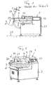
- FIG. 1 shows a cutter according to the prior art as an example.
- the ingredients are conveyed past the rotating knives fastened to the knife shaft and comminuted and emulsified until the sausage mass has the desired consistency for further processing.
- the machine stand of such a cutter which is dimensioned to accommodate all driving forces and driving torques, is expensive to produce. Since cutters for food processing are largely made of stainless steel, the material thicknesses required for the machine stand lead to high material costs.
- the object of the present invention is to provide an improved cutter.
- a support element is provided which can be dimensioned separately from the machine frame such that it absorbs the high forces and moments occurring during operation of the cutter, so that the machine frame is completely relieved of it. Does not absorb the inclusion of these forces and moments in the machine frame and this only has to wear the carrier, the machine frame can be significantly filigree and thus built material and cheaper than conventional cutters.
- the method according to the invention allows a simplification in the manufacture of a cutter.
- FIG. 1 shows a cutter 1 according to the prior art, in which a machine stand 15 is provided, which carries the cutter bowl 2, which is coverable with a hinged lid 9.
- a machine stand 15 which carries the cutter bowl 2, which is coverable with a hinged lid 9.
- the rotary drive for the cutter bowl 2 is provided inside the machine stand 15. This is rotated about a standing surface 28 substantially perpendicular axis, which is mounted in the machine stand 15.
- the blade shaft is mounted, which extends substantially horizontally and projects over the bowl.
- the knife shaft carries the cutter blades, which engage in the bowl.
- the cutter blades are covered by a cover 10 in operation.
- the drive motor for the knife shaft and the drive means for transmitting the driving force from the engine the knife shaft are also arranged in the machine stand 15.
- an ejector 27 may be provided, which has an ejector 30 which is driven by a motor 29 to rotate, and which for ejecting the finished Product is pivotable in the cutter bowl (arrow A). Also, the ejector 27 is attached to the machine stand 15. As explained at the beginning, high forces and moments occur during cutting.
- the knife shaft drive can have a motor with a power of about 37 kW and the bowl drive a motor with a power of 0.55 kW. If an ejector is provided, its motor may have a power of 0.75 kW. For larger cutters, significantly higher power outputs are provided.
- a carrier 6 is provided, on which the cutter bowl 2 and the rotary drive 3 are arranged.
- This drive 3 may be an electric motor, possibly with a transmission.
- the drive motor 5 for the not visible, but indicated by a broken line 4 blade shaft and the blade shaft itself are arranged on the support 6.
- this drive motor is for example an electric motor.
- the knife shaft carries in a known manner, only indicated here cutter knife 4 '. From the motor 5 may be provided as a drive means for the blade shaft 4, a belt 8.
- the carrier 6, which in this example has a base 16, an arm 17 angled therefrom and another arm 18, which in turn is angled away from the first arm 17, thus forms a separate, independent support for all said drive elements and the "tools" of Cutter or the cutterhead and the knife shaft with the knives and thus absorbs all forces and moments that arise in the cutter mode.
- the carrier 6 is dimensioned accordingly, to be able to absorb these forces; it is preferably constructed of stainless steel.
- the carrier is not independently operable and must be positioned opposite the base of the cutter.
- the machine frame 7 provided for this purpose can only be dimensioned in such a way that it can support the carrier 6 including the filled cutter bowl or position it in relation to the standing surface, thanks to the support, which is separate from it in terms of driving force.
- the machine frame 7 need not be constructed and dimensioned for receiving the driving forces. This allows a significant material and cost savings. For example, it is possible to provide the machine frame with supporting plates of stainless steel of only 3 mm thickness, which would not be possible if the carrier 6 did not absorb all driving forces and moments.
- the carrier 6 is releasably secured to the machine frame 7 with known fastening means, for example by means of screws and / or studs, as in FIG. 3 indicated. From the carrier only lead electrical connection lines for the drives in the machine frame.
- the construction with a separate carrier 6 also makes it possible to lift the carrier 6 with the drive elements from the machine frame 7 or to build it up during manufacture on the machine frame, as shown in FIG. 2 is shown.
- the drive elements for maintenance and repair work but also for the initial installation are easily accessible.
- the lifting or building can be done with a crane corresponding capacity in a simple way.
- the machine frame 7 receives the control panel 13. Further, it houses the electric part 11 of the aforementioned drive means and the control of the cutter. It may have a ventilation element 12 for the electronic assemblies.
- the carrier 6 also carries the blade cover 10 and the lid 9 for the cutter bowl 2. This Elements can be pivoted together about a hinge 20 to allow access to the cutter bowl and the knife holder.
- the front part of the cutter cover 9 can, in a manner known per se, be separately pivotable, for which purpose a handle 19 and a hinge 21 are provided.
- connection surface 22 (covered here) may be provided which carries fastening means for the optional ejector and provides the electrical connections.
- the ejector is not shown here, since in principle functioning according to the prior art, in detail.
Landscapes
- Engineering & Computer Science (AREA)
- Food Science & Technology (AREA)
- Crushing And Pulverization Processes (AREA)
- Food-Manufacturing Devices (AREA)
- Threshing Machine Elements (AREA)
- Details Of Cutting Devices (AREA)
Abstract
Description
- Die Erfindung betrifft einen Kutter, umfassend eine Kutterschüssel mit einem Drehantrieb, eine über der Kutterschüssel verlaufende Messerwelle und einen Messerwellenantrieb. Ferner betrifft die Erfindung ein Verfahren zur Herstellung eines Kutters.
- Derartige Kutter sind in vielfältiger Ausgestaltung bekannt und werden insbesondere für die Herstellung von Wurstmasse (Wurstbrät) verwendet.
Figur 1 zeigt einen Kutter nach Stand der Technik als Beispiel. In der sich mittels des Drehantriebs umlaufend drehenden Kutterschüssel werden die Zutaten an den an der Messerwelle befestigten, rotierenden Messern vorbeigefördert und zerkleinert und emulgiert, bis die Wurstmasse die gewünschte Konsistenz für die Weiterverarbeitung aufweist. Der zur Aufnahme aller Antriebskräfte und Antriebsmomente dimensionierte Maschinenständer eines solchen Kutters ist aufwändig in der Herstellung. Da Kutter für die Lebensmittelverarbeitung weitgehend aus rostfreiem Stahl gefertigt werden, führen die für den Maschinenständer notwendigen Materialstärken zu hohen Materialkosten. - Aufgabe der vorliegenden Neuerung ist es, einen verbesserten Kutter zu schaffen.
- Dies wird bei einem Kutter der eingangs genannten Art dadurch erzielt, dass die Kutterschüssel und deren Drehantrieb sowie die Messerwelle und deren Messerwellenantrieb an einem gemeinsamen Träger angeordnet sind, welcher auf einem davon separaten Maschinengestell des Kutters aufgesetzt ist, welches den Träger gegenüber einer Stellfläche positioniert.
- Mittels des separaten Trägers, der die Antriebselemente und die bewegten Werkzeuge bzw. die Kutterschüssel, die Messerwelle und damit auch die Messer aufnimmt, ist ein Tragelement geschaffen, dass separat vom Maschinengestell derart dimensioniert werden kann, dass es die beim Betrieb des Kutters auftretenden hohen Kräfte und Momente aufnimmt, so dass das Maschinengestell davon vollständig entlastet wird. Entfällt die Aufnahme dieser Kräfte und Momente im Maschinengestell und hat dieses lediglich den Träger zu tragen, kann das Maschinengestell deutlich filigraner und damit material- und kostengünstiger gebaut sein, als bei herkömmlichen Kuttern.
- Das Verfahren gemäss der Erfindung erlaubt eine Vereinfachung bei der Herstellung eines Kutters.
- Im Folgenden werden Ausführungsbeispiele der Erfindung anhand der Zeichnungen näher erläutert. Dabei zeigt
-
Figur 1 eine Frontalansicht eines Kutters nach Stand der Technik; -
Figur 2 eine schaubildliche Ansicht eines Kutters gemäss der Neuerung; und -
Figur 3 den Kutter vonFigur 2 in einer Darstellung, bei welcher der Träger vom Maschinengestell getrennt gezeigt ist. -
Figur 1 zeigt einen Kutter 1 nach Stand der Technik, bei welchem ein Maschinenständer 15 vorgesehen ist, der die Kutterschüssel 2 trägt, die mit einem schwenkbaren Deckel 9 abdeckbar ist. Im Inneren des Maschinenständers 15 ist der Drehantrieb für die Kutterschüssel 2 vorgesehen. Diese wird um eine zur Standfläche 28 im Wesentlichen senkrechte Achse gedreht, welche im Maschinenständer 15 gelagert ist. Ebenfalls im Ständer 15 ist die Messerwelle gelagert, welche im Wesentlichen horizontal verläuft und über die Schüssel ragt. An ihrem schüsselseitigen Ende trägt die Messerwelle die Kuttermesser, welche in die Schüssel eingreifen. Die Kuttermesser sind durch eine Abdeckung 10 im Betrieb abgedeckt. Der Antriebsmotor für die Messerwelle und die Antriebsmittel zur Übertragung der Antriebskraft vom Motor auf die Messerwelle sind ebenfalls im Maschinenständer 15 angeordnet. Ferner nimmt dieser die Steuerung des Kutters auf und trägt einen Bedienungsteil 13. Als Option für eine einfache Entleerung des Kutters kann ein Auswerfer 27 vorgesehen sein, welcher eine Auswerferscheibe 30 aufweist, welche von einem Motor 29 drehend angetrieben wird, und welche zum Auswerfen des fertigen Produktes in die Kutterschüssel schwenkbar ist (Pfeil A). Auch der Auswerfer 27 ist am Maschinenständer 15 befestigt. Wie eingangs erläutert, treten beim Kuttern hohe Kräfte und Momente auf. So kann z.B. der Messerwellenantrieb einen Motor mit einer Leistung von ca. 37 kW aufweisen und der Schüsselantrieb einen Motor mit einer Leistung von 0,55 kW. Ist ein Auswerfer vorgesehen, so kann sein Motor eine Leistung von 0,75 kW aufweisen. Bei grösseren Kuttern sind deutlich höhere Leistungen der Antriebe vorgesehen. - Die
Figuren 2 und3 zeigen einen neuerungsgemässen Kutter 1. Es ist aus diesen Figuren ersichtlich, dass gemäss der Neuerung ein Träger 6 vorgesehen ist, an welchem die Kutterschüssel 2 und deren Drehantrieb 3 angeordnet sind. Dieser Antrieb 3 kann ein Elektromotor sein, allenfalls mit einem Getriebe. Weiter sind an dem Träger 6 der Antriebsmotor 5 für die nicht ersichtliche, aber durch eine unterbrochene Linie 4 angedeutete Messerwelle und die Messerwelle selber angeordnet. Auch dieser Antriebsmotor ist z.B. ein Elektromotor. Die Messerwelle trägt auf bekannte Weise die hier nur angedeuteten Kuttermesser 4'. Vom Motor 5 kann als Antriebsmittel zur Messerwelle 4 ein Riemen 8 vorgesehen sein. Der Träger 6, der in diesem Beispiel eine Basis 16, einen davon abgewinkelten Arm 17 und einen weiteren Arm 18 aufweist, der wiederum vom ersten Arm 17 abgewinkelt ist, bildet somit einen separaten, eigenständigen Träger für alle genannten Antriebselemente und die "Werkzeuge" des Kutters bzw. die Kutterschüssel und die Messerwelle mit den Messern und nimmt somit alle Kräfte und Momente auf, die im Kutterbetrieb entstehen. Der Träger 6 wird entsprechend dimensioniert, um diese Kräfte aufnehmen zu können; er ist bevorzugt aus rostfreiem Stahl aufgebaut. Der Träger ist aber nicht selbständig betriebsfähig und muss gegenüber der Standfläche des Kutters positioniert werden. Das dafür vorgesehene Maschinengestell 7 ist dank des davon antriebskraftmässig separaten Trägers nur derart zu dimensionieren, dass es den Träger 6 inklusive der befüllten Kutterschüssel tragen kann bzw. zur Standfläche positionieren kann. Das Maschinengestell 7 braucht aber nicht für die Aufnahme der Antriebskräfte konstruiert und dimensioniert zu sein. Dies ermöglicht eine wesentliche Material- und Kostenersparnis. So ist es z.B. möglich, das Maschinengestell mit tragenden Platten aus rostfreiem Stahl von nur 3 mm Dicke zu versehen, was nicht möglich wäre, wenn nicht der Träger 6 alle Antriebskräfte und Momente aufnehmen würde. Der Träger 6 ist am Maschinengestell 7 mit bekannten Befestigungsmitteln lösbar befestigt, z.B. mittels Schrauben und/oder Stehbolzen, wie inFigur 3 angedeutet. Vom Träger führen lediglich elektrische Anschlussleitungen für die Antriebe in das Maschinengestell. - Der Aufbau mit einem separaten Träger 6 macht es auch möglich, den Träger 6 mit den Antriebselementen vom Maschinengestell 7 abzuheben bzw. bei der Herstellung auf dem Maschinengestell aufzubauen, wie dies in
Figur 2 gezeigt ist. Dadurch werden die Antriebselemente für Wartungs- und Reparaturarbeiten aber auch für die Erstmontage einfach zugänglich. Das Abheben bzw. das Aufbauen kann mit einem Kran entsprechender Tragkraft auf einfache Weise erfolgen. - Das Maschinengestell 7 nimmt die Bedienungstafel 13 auf. Ferner beherbergt es den elektrischen Teil 11 der vorgenannten Antriebsmittel und die Steuerung des Kutters. Es kann ein Lüftungselement 12 für die elektronischen Baugruppen aufweisen.
- Der Träger 6 trägt ebenfalls die Messerabdeckung 10 und den Deckel 9 für die Kutterschüssel 2. Diese Elemente können zusammen um ein Scharnier 20 schwenkbar sein, um den Zugang zur Kutterschüssel und zur Messeraufnahme zu ermöglichen. Der vordere Teil des Kutterdeckels 9 kann, auf an sich bekannte Weise, separat schwenkbar sein, wozu ein Griff 19 und ein Scharnier 21 vorgesehen ist.
- Soll ein Auswerfer vorgesehen werden, so wird dieser bevorzugt ebenfalls am Träger 6 befestigt, so dass auch die durch den Auswerfer hervorgerufenen Kräfte durch den Träger 6 aufgenommen werden und nicht auf das Maschinengestell 7 einwirken. Es kann dazu eine (hier abgedeckte) Anschlussfläche 22 vorgesehen sein, welche Befestigungsmittel für den optionalen Auswerfer trägt und die elektrischen Anschlüsse bereitstellt. Der Auswerfer wird hier, da grundsätzlich gemäss dem Stand der Technik funktionierend, nicht näher dargestellt.
Claims (6)
- Kutter (1), umfassend eine Kutterschüssel (2) mit einem Drehantrieb (3), eine über der Kutterschüssel verlaufende Messerwelle (4) und einen Messerwellenantrieb (5), dadurch gekennzeichnet, dass die Kutterschüssel (2), deren Drehantrieb (3), die Messerwelle (4) sowie deren Messerwellenantrieb (5, 8) an einem gemeinsamen Träger (6, 16, 17, 18) angeordnet sind, welcher auf einem davon separaten Maschinengestell (7) des Kutters (1) aufgesetzt ist, welches den Träger (6, 16, 17, 18) gegenüber einer Standfläche (28) positioniert.
- Kutter nach Anspruch 1, dadurch gekennzeichnet, dass am Träger (6) ein Auswerfer (27) mit einer in die Kutterschüssel schwenkbaren angetriebenen Auswerferscheibe (28) befestigt ist.
- Kutter nach Anspruch 1 oder 2, dadurch gekennzeichnet, dass am Träger eine schwenkbare Abdeckung (9, 10) für die Kutterschüssel angeordnet ist.
- Kutter nach einem der Ansprüche 1 bis 3,
dadurch gekennzeichnet, dass das Maschinengestell eine Bedienungstafel (13) für die Kutterbedienung trägt. - Kutter nach einem der Ansprüche 1 bis 4,
dadurch gekennzeichnet, dass das Maschinengestell eine Steuerung des Kutters sowie elektrische Komponenten zur elektrischen Speisung der Antriebe (3, 5) beherbergt. - Verfahren zur Herstellung eines Kutters (1), umfassend eine Kutterschüssel (2) mit einem Drehantrieb (3), eine über der Kutterschüssel verlaufende Messerwelle (4) und einen Messerwellenantrieb (5), dadurch gekennzeichnet, dass die Kutterschüssel (2), deren Drehantrieb (3), die Messerwelle (4) sowie deren Messerwellenantrieb (5, 8) an einem gemeinsamen Träger (6, 16, 17, 18) angeordnet werden, und dass dieser Träger auf einem davon separaten Maschinengestell (7) des Kutters (1) aufgesetzt wird, welches ausgestaltet ist, um den Träger (6, 16, 17, 18) gegenüber einer Standfläche (28) zu positionieren.
Priority Applications (1)
| Application Number | Priority Date | Filing Date | Title |
|---|---|---|---|
| PL10005563T PL2258482T3 (pl) | 2009-06-04 | 2010-05-28 | Kuter |
Applications Claiming Priority (1)
| Application Number | Priority Date | Filing Date | Title |
|---|---|---|---|
| DE202009007888U DE202009007888U1 (de) | 2009-06-04 | 2009-06-04 | Kutter |
Publications (3)
| Publication Number | Publication Date |
|---|---|
| EP2258482A2 true EP2258482A2 (de) | 2010-12-08 |
| EP2258482A3 EP2258482A3 (de) | 2011-07-20 |
| EP2258482B1 EP2258482B1 (de) | 2013-06-12 |
Family
ID=40984587
Family Applications (1)
| Application Number | Title | Priority Date | Filing Date |
|---|---|---|---|
| EP10005563.1A Not-in-force EP2258482B1 (de) | 2009-06-04 | 2010-05-28 | Kutter |
Country Status (4)
| Country | Link |
|---|---|
| EP (1) | EP2258482B1 (de) |
| DE (1) | DE202009007888U1 (de) |
| ES (1) | ES2425979T3 (de) |
| PL (1) | PL2258482T3 (de) |
Cited By (1)
| Publication number | Priority date | Publication date | Assignee | Title |
|---|---|---|---|---|
| CN108522617A (zh) * | 2018-01-30 | 2018-09-14 | 韦德高 | 一种肉沫加工设备 |
Family Cites Families (3)
| Publication number | Priority date | Publication date | Assignee | Title |
|---|---|---|---|---|
| DE1209907B (de) * | 1964-07-28 | 1966-01-27 | Alexanderwerk Ag | Vorrichtung zum Leeren der Schuessel an Fleisch-kuttern |
| DE3033145C2 (de) * | 1980-09-03 | 1983-08-18 | Modell- und Maschinenfabrik Meissner & Co, 3560 Biedenkopf | Fleischkutter |
| DE19708547A1 (de) * | 1995-09-05 | 1998-09-10 | Max Norbisrath | Kutter zum Schneiden und Mischen von Lebensmittel |
-
2009
- 2009-06-04 DE DE202009007888U patent/DE202009007888U1/de not_active Expired - Lifetime
-
2010
- 2010-05-28 PL PL10005563T patent/PL2258482T3/pl unknown
- 2010-05-28 ES ES10005563T patent/ES2425979T3/es active Active
- 2010-05-28 EP EP10005563.1A patent/EP2258482B1/de not_active Not-in-force
Non-Patent Citations (1)
| Title |
|---|
| None |
Cited By (1)
| Publication number | Priority date | Publication date | Assignee | Title |
|---|---|---|---|---|
| CN108522617A (zh) * | 2018-01-30 | 2018-09-14 | 韦德高 | 一种肉沫加工设备 |
Also Published As
| Publication number | Publication date |
|---|---|
| ES2425979T3 (es) | 2013-10-18 |
| DE202009007888U1 (de) | 2009-08-20 |
| EP2258482A3 (de) | 2011-07-20 |
| EP2258482B1 (de) | 2013-06-12 |
| PL2258482T3 (pl) | 2013-11-29 |
Similar Documents
| Publication | Publication Date | Title |
|---|---|---|
| DE69002992T2 (de) | Mischanhänger für faserige Produkte. | |
| EP2110231A2 (de) | Rundläufer-Tablettenpresse | |
| DE102009008448A1 (de) | Vorrichtung zum Zerkleinern von Aufgabegut mit Abstreifelementen | |
| DE102018212162B4 (de) | Zufuhreinrichtung für eine Saftpresse, Küchenmaschine und Saftpresse mit Zufuhreinrichtung | |
| DE202012007418U1 (de) | Zerkleinerungsvorrichtung | |
| EP1639928B1 (de) | Messersatz für eine elektromotorisch betriebene Küchenmaschine sowie Küchenmaschine hierzu | |
| DE69821792T2 (de) | Schneidevorrichtung | |
| EP2082807A1 (de) | Zerkleinerungsvorrichtung mit gegenläufigen Rotoren | |
| EP1071343A1 (de) | Vorrichtung zur zerkleinerung von organischen substanzen | |
| DE69104194T2 (de) | Anlage für materialzerkleinerung. | |
| EP2258482B1 (de) | Kutter | |
| CH616090A5 (de) | ||
| DE102007040046B4 (de) | Rotorshredder | |
| EP2492405B1 (de) | Entsorgungsvorrichtung für organische Küchenabfälle sowie Mitnehmer für eine solche Entsorgungsvorrichtung | |
| WO2008011995A1 (de) | Rohstoffannahme-, druck- und förderschneckensystem für lebensmittelzerkleinerungsmaschinen | |
| EP1575708A1 (de) | Zerkleinerungsmaschine für material beliebiger art, z. b. abfall oder holz | |
| DE4126910C1 (de) | ||
| DE2315719A1 (de) | Vorrichtung zum spanabhebenden bearbeiten der kanten von werkstueckplatten | |
| DE3036235A1 (de) | Handgeraet zum zerkleinern von haus- und gartenabfaellen | |
| DE69931002T2 (de) | Vorrichtung zum Zerkleinern von synthetischen oder natürlichen organischen Materialien, wie z.B. Holz | |
| DE2922263C2 (de) | Mischanlage | |
| WO1989007388A1 (fr) | Procede et dispositif de decoupage de fourrage comprime au moins jusqu'a une pression de stockage | |
| DE60223450T2 (de) | Vorrichtung zum Strangpressen und Nassformen von Ton | |
| CN219580685U (zh) | 竹盐加工用粉碎装置 | |
| DE202006006011U1 (de) | Aktenvernichter mit zwei zueinander parallelen Antriebsachsen |
Legal Events
| Date | Code | Title | Description |
|---|---|---|---|
| PUAI | Public reference made under article 153(3) epc to a published international application that has entered the european phase |
Free format text: ORIGINAL CODE: 0009012 |
|
| AK | Designated contracting states |
Kind code of ref document: A2 Designated state(s): AL AT BE BG CH CY CZ DE DK EE ES FI FR GB GR HR HU IE IS IT LI LT LU LV MC MK MT NL NO PL PT RO SE SI SK SM TR |
|
| AX | Request for extension of the european patent |
Extension state: BA ME RS |
|
| PUAL | Search report despatched |
Free format text: ORIGINAL CODE: 0009013 |
|
| AK | Designated contracting states |
Kind code of ref document: A3 Designated state(s): AL AT BE BG CH CY CZ DE DK EE ES FI FR GB GR HR HU IE IS IT LI LT LU LV MC MK MT NL NO PL PT RO SE SI SK SM TR |
|
| AX | Request for extension of the european patent |
Extension state: BA ME RS |
|
| 17P | Request for examination filed |
Effective date: 20111031 |
|
| GRAP | Despatch of communication of intention to grant a patent |
Free format text: ORIGINAL CODE: EPIDOSNIGR1 |
|
| GRAS | Grant fee paid |
Free format text: ORIGINAL CODE: EPIDOSNIGR3 |
|
| GRAA | (expected) grant |
Free format text: ORIGINAL CODE: 0009210 |
|
| AK | Designated contracting states |
Kind code of ref document: B1 Designated state(s): AL AT BE BG CH CY CZ DE DK EE ES FI FR GB GR HR HU IE IS IT LI LT LU LV MC MK MT NL NO PL PT RO SE SI SK SM TR |
|
| REG | Reference to a national code |
Ref country code: GB Ref legal event code: FG4D Free format text: NOT ENGLISH |
|
| REG | Reference to a national code |
Ref country code: CH Ref legal event code: NV Representative=s name: E. BLUM AND CO. AG PATENT- UND MARKENANWAELTE , CH Ref country code: CH Ref legal event code: EP |
|
| REG | Reference to a national code |
Ref country code: AT Ref legal event code: REF Ref document number: 616475 Country of ref document: AT Kind code of ref document: T Effective date: 20130615 |
|
| REG | Reference to a national code |
Ref country code: IE Ref legal event code: FG4D Free format text: LANGUAGE OF EP DOCUMENT: GERMAN |
|
| REG | Reference to a national code |
Ref country code: DE Ref legal event code: R096 Ref document number: 502010003620 Country of ref document: DE Effective date: 20130808 |
|
| REG | Reference to a national code |
Ref country code: ES Ref legal event code: FG2A Ref document number: 2425979 Country of ref document: ES Kind code of ref document: T3 Effective date: 20131018 |
|
| PG25 | Lapsed in a contracting state [announced via postgrant information from national office to epo] |
Ref country code: GR Free format text: LAPSE BECAUSE OF FAILURE TO SUBMIT A TRANSLATION OF THE DESCRIPTION OR TO PAY THE FEE WITHIN THE PRESCRIBED TIME-LIMIT Effective date: 20130913 Ref country code: FI Free format text: LAPSE BECAUSE OF FAILURE TO SUBMIT A TRANSLATION OF THE DESCRIPTION OR TO PAY THE FEE WITHIN THE PRESCRIBED TIME-LIMIT Effective date: 20130612 Ref country code: SI Free format text: LAPSE BECAUSE OF FAILURE TO SUBMIT A TRANSLATION OF THE DESCRIPTION OR TO PAY THE FEE WITHIN THE PRESCRIBED TIME-LIMIT Effective date: 20130612 Ref country code: LT Free format text: LAPSE BECAUSE OF FAILURE TO SUBMIT A TRANSLATION OF THE DESCRIPTION OR TO PAY THE FEE WITHIN THE PRESCRIBED TIME-LIMIT Effective date: 20130612 Ref country code: SE Free format text: LAPSE BECAUSE OF FAILURE TO SUBMIT A TRANSLATION OF THE DESCRIPTION OR TO PAY THE FEE WITHIN THE PRESCRIBED TIME-LIMIT Effective date: 20130612 Ref country code: NO Free format text: LAPSE BECAUSE OF FAILURE TO SUBMIT A TRANSLATION OF THE DESCRIPTION OR TO PAY THE FEE WITHIN THE PRESCRIBED TIME-LIMIT Effective date: 20130912 |
|
| REG | Reference to a national code |
Ref country code: NL Ref legal event code: VDEP Effective date: 20130612 |
|
| REG | Reference to a national code |
Ref country code: LT Ref legal event code: MG4D |
|
| PG25 | Lapsed in a contracting state [announced via postgrant information from national office to epo] |
Ref country code: BG Free format text: LAPSE BECAUSE OF FAILURE TO SUBMIT A TRANSLATION OF THE DESCRIPTION OR TO PAY THE FEE WITHIN THE PRESCRIBED TIME-LIMIT Effective date: 20130912 Ref country code: HR Free format text: LAPSE BECAUSE OF FAILURE TO SUBMIT A TRANSLATION OF THE DESCRIPTION OR TO PAY THE FEE WITHIN THE PRESCRIBED TIME-LIMIT Effective date: 20130612 |
|
| REG | Reference to a national code |
Ref country code: PL Ref legal event code: T3 |
|
| PG25 | Lapsed in a contracting state [announced via postgrant information from national office to epo] |
Ref country code: LV Free format text: LAPSE BECAUSE OF FAILURE TO SUBMIT A TRANSLATION OF THE DESCRIPTION OR TO PAY THE FEE WITHIN THE PRESCRIBED TIME-LIMIT Effective date: 20130612 |
|
| PG25 | Lapsed in a contracting state [announced via postgrant information from national office to epo] |
Ref country code: SK Free format text: LAPSE BECAUSE OF FAILURE TO SUBMIT A TRANSLATION OF THE DESCRIPTION OR TO PAY THE FEE WITHIN THE PRESCRIBED TIME-LIMIT Effective date: 20130612 Ref country code: IS Free format text: LAPSE BECAUSE OF FAILURE TO SUBMIT A TRANSLATION OF THE DESCRIPTION OR TO PAY THE FEE WITHIN THE PRESCRIBED TIME-LIMIT Effective date: 20131012 Ref country code: CZ Free format text: LAPSE BECAUSE OF FAILURE TO SUBMIT A TRANSLATION OF THE DESCRIPTION OR TO PAY THE FEE WITHIN THE PRESCRIBED TIME-LIMIT Effective date: 20130612 Ref country code: PT Free format text: LAPSE BECAUSE OF FAILURE TO SUBMIT A TRANSLATION OF THE DESCRIPTION OR TO PAY THE FEE WITHIN THE PRESCRIBED TIME-LIMIT Effective date: 20131014 Ref country code: EE Free format text: LAPSE BECAUSE OF FAILURE TO SUBMIT A TRANSLATION OF THE DESCRIPTION OR TO PAY THE FEE WITHIN THE PRESCRIBED TIME-LIMIT Effective date: 20130612 |
|
| PG25 | Lapsed in a contracting state [announced via postgrant information from national office to epo] |
Ref country code: RO Free format text: LAPSE BECAUSE OF FAILURE TO SUBMIT A TRANSLATION OF THE DESCRIPTION OR TO PAY THE FEE WITHIN THE PRESCRIBED TIME-LIMIT Effective date: 20130612 Ref country code: NL Free format text: LAPSE BECAUSE OF FAILURE TO SUBMIT A TRANSLATION OF THE DESCRIPTION OR TO PAY THE FEE WITHIN THE PRESCRIBED TIME-LIMIT Effective date: 20130612 |
|
| PLBE | No opposition filed within time limit |
Free format text: ORIGINAL CODE: 0009261 |
|
| STAA | Information on the status of an ep patent application or granted ep patent |
Free format text: STATUS: NO OPPOSITION FILED WITHIN TIME LIMIT |
|
| PG25 | Lapsed in a contracting state [announced via postgrant information from national office to epo] |
Ref country code: DK Free format text: LAPSE BECAUSE OF FAILURE TO SUBMIT A TRANSLATION OF THE DESCRIPTION OR TO PAY THE FEE WITHIN THE PRESCRIBED TIME-LIMIT Effective date: 20130612 |
|
| 26N | No opposition filed |
Effective date: 20140313 |
|
| REG | Reference to a national code |
Ref country code: DE Ref legal event code: R097 Ref document number: 502010003620 Country of ref document: DE Effective date: 20140313 |
|
| PGFP | Annual fee paid to national office [announced via postgrant information from national office to epo] |
Ref country code: DE Payment date: 20140521 Year of fee payment: 5 |
|
| PGFP | Annual fee paid to national office [announced via postgrant information from national office to epo] |
Ref country code: PL Payment date: 20140425 Year of fee payment: 5 |
|
| PG25 | Lapsed in a contracting state [announced via postgrant information from national office to epo] |
Ref country code: LU Free format text: LAPSE BECAUSE OF FAILURE TO SUBMIT A TRANSLATION OF THE DESCRIPTION OR TO PAY THE FEE WITHIN THE PRESCRIBED TIME-LIMIT Effective date: 20140528 |
|
| REG | Reference to a national code |
Ref country code: CH Ref legal event code: PL |
|
| GBPC | Gb: european patent ceased through non-payment of renewal fee |
Effective date: 20140528 |
|
| PG25 | Lapsed in a contracting state [announced via postgrant information from national office to epo] |
Ref country code: CH Free format text: LAPSE BECAUSE OF NON-PAYMENT OF DUE FEES Effective date: 20140531 Ref country code: LI Free format text: LAPSE BECAUSE OF NON-PAYMENT OF DUE FEES Effective date: 20140531 Ref country code: MC Free format text: LAPSE BECAUSE OF FAILURE TO SUBMIT A TRANSLATION OF THE DESCRIPTION OR TO PAY THE FEE WITHIN THE PRESCRIBED TIME-LIMIT Effective date: 20130612 |
|
| REG | Reference to a national code |
Ref country code: IE Ref legal event code: MM4A |
|
| REG | Reference to a national code |
Ref country code: FR Ref legal event code: ST Effective date: 20150130 |
|
| PG25 | Lapsed in a contracting state [announced via postgrant information from national office to epo] |
Ref country code: IT Free format text: LAPSE BECAUSE OF NON-PAYMENT OF DUE FEES Effective date: 20140528 Ref country code: IE Free format text: LAPSE BECAUSE OF NON-PAYMENT OF DUE FEES Effective date: 20140528 |
|
| PG25 | Lapsed in a contracting state [announced via postgrant information from national office to epo] |
Ref country code: FR Free format text: LAPSE BECAUSE OF NON-PAYMENT OF DUE FEES Effective date: 20140602 Ref country code: GB Free format text: LAPSE BECAUSE OF NON-PAYMENT OF DUE FEES Effective date: 20140528 |
|
| REG | Reference to a national code |
Ref country code: ES Ref legal event code: FD2A Effective date: 20150626 |
|
| PG25 | Lapsed in a contracting state [announced via postgrant information from national office to epo] |
Ref country code: ES Free format text: LAPSE BECAUSE OF NON-PAYMENT OF DUE FEES Effective date: 20140529 |
|
| REG | Reference to a national code |
Ref country code: DE Ref legal event code: R119 Ref document number: 502010003620 Country of ref document: DE |
|
| PG25 | Lapsed in a contracting state [announced via postgrant information from national office to epo] |
Ref country code: MT Free format text: LAPSE BECAUSE OF FAILURE TO SUBMIT A TRANSLATION OF THE DESCRIPTION OR TO PAY THE FEE WITHIN THE PRESCRIBED TIME-LIMIT Effective date: 20130612 |
|
| PG25 | Lapsed in a contracting state [announced via postgrant information from national office to epo] |
Ref country code: DE Free format text: LAPSE BECAUSE OF NON-PAYMENT OF DUE FEES Effective date: 20151201 Ref country code: SM Free format text: LAPSE BECAUSE OF FAILURE TO SUBMIT A TRANSLATION OF THE DESCRIPTION OR TO PAY THE FEE WITHIN THE PRESCRIBED TIME-LIMIT Effective date: 20130612 |
|
| PG25 | Lapsed in a contracting state [announced via postgrant information from national office to epo] |
Ref country code: CY Free format text: LAPSE BECAUSE OF FAILURE TO SUBMIT A TRANSLATION OF THE DESCRIPTION OR TO PAY THE FEE WITHIN THE PRESCRIBED TIME-LIMIT Effective date: 20130612 |
|
| REG | Reference to a national code |
Ref country code: AT Ref legal event code: MM01 Ref document number: 616475 Country of ref document: AT Kind code of ref document: T Effective date: 20150528 |
|
| PG25 | Lapsed in a contracting state [announced via postgrant information from national office to epo] |
Ref country code: BE Free format text: LAPSE BECAUSE OF FAILURE TO SUBMIT A TRANSLATION OF THE DESCRIPTION OR TO PAY THE FEE WITHIN THE PRESCRIBED TIME-LIMIT Effective date: 20140531 Ref country code: TR Free format text: LAPSE BECAUSE OF FAILURE TO SUBMIT A TRANSLATION OF THE DESCRIPTION OR TO PAY THE FEE WITHIN THE PRESCRIBED TIME-LIMIT Effective date: 20130612 Ref country code: HU Free format text: LAPSE BECAUSE OF FAILURE TO SUBMIT A TRANSLATION OF THE DESCRIPTION OR TO PAY THE FEE WITHIN THE PRESCRIBED TIME-LIMIT; INVALID AB INITIO Effective date: 20100528 |
|
| PG25 | Lapsed in a contracting state [announced via postgrant information from national office to epo] |
Ref country code: PL Free format text: LAPSE BECAUSE OF NON-PAYMENT OF DUE FEES Effective date: 20150528 Ref country code: AT Free format text: LAPSE BECAUSE OF NON-PAYMENT OF DUE FEES Effective date: 20150528 |
|
| PG25 | Lapsed in a contracting state [announced via postgrant information from national office to epo] |
Ref country code: MK Free format text: LAPSE BECAUSE OF FAILURE TO SUBMIT A TRANSLATION OF THE DESCRIPTION OR TO PAY THE FEE WITHIN THE PRESCRIBED TIME-LIMIT Effective date: 20130612 |
|
| PG25 | Lapsed in a contracting state [announced via postgrant information from national office to epo] |
Ref country code: AL Free format text: LAPSE BECAUSE OF FAILURE TO SUBMIT A TRANSLATION OF THE DESCRIPTION OR TO PAY THE FEE WITHIN THE PRESCRIBED TIME-LIMIT Effective date: 20130612 |