EP2257384B1 - Spritzpistolensystem - Google Patents
Spritzpistolensystem Download PDFInfo
- Publication number
- EP2257384B1 EP2257384B1 EP09715863.8A EP09715863A EP2257384B1 EP 2257384 B1 EP2257384 B1 EP 2257384B1 EP 09715863 A EP09715863 A EP 09715863A EP 2257384 B1 EP2257384 B1 EP 2257384B1
- Authority
- EP
- European Patent Office
- Prior art keywords
- spray gun
- housing
- spray
- gun system
- receiving device
- Prior art date
- Legal status (The legal status is an assumption and is not a legal conclusion. Google has not performed a legal analysis and makes no representation as to the accuracy of the status listed.)
- Not-in-force
Links
Images

Classifications
-
- B—PERFORMING OPERATIONS; TRANSPORTING
- B05—SPRAYING OR ATOMISING IN GENERAL; APPLYING FLUENT MATERIALS TO SURFACES, IN GENERAL
- B05B—SPRAYING APPARATUS; ATOMISING APPARATUS; NOZZLES
- B05B7/00—Spraying apparatus for discharge of liquids or other fluent materials from two or more sources, e.g. of liquid and air, of powder and gas
- B05B7/24—Spraying apparatus for discharge of liquids or other fluent materials from two or more sources, e.g. of liquid and air, of powder and gas with means, e.g. a container, for supplying liquid or other fluent material to a discharge device
- B05B7/2402—Apparatus to be carried on or by a person, e.g. by hand; Apparatus comprising containers fixed to the discharge device
- B05B7/2405—Apparatus to be carried on or by a person, e.g. by hand; Apparatus comprising containers fixed to the discharge device using an atomising fluid as carrying fluid for feeding, e.g. by suction or pressure, a carried liquid from the container to the nozzle
- B05B7/2416—Apparatus to be carried on or by a person, e.g. by hand; Apparatus comprising containers fixed to the discharge device using an atomising fluid as carrying fluid for feeding, e.g. by suction or pressure, a carried liquid from the container to the nozzle characterised by the means for producing or supplying the atomising fluid, e.g. air hoses, air pumps, gas containers, compressors, fans, ventilators, their drives
Definitions
- the present invention relates to a spray gun system
- a spray gun system comprising a spray gun for dispensing a Spritguts to which a Spritzgutability constituer is attachable; a base device with a housing in which a compressed air generating device is accommodated; and a compressed air hose connectable to the spray gun and the base device to connect them together.
- Spray gun systems of the aforementioned type are known in the prior art in a variety of configurations, see for example DE-A-10 2005 041 488 . DE-A-10 2005 006 360 . WO 01/24941 A . US 5,181,832 A and US 5294 413 A , Sprays can be sprayed with spray gun systems of this kind, in particular water-dilutable and solvent-containing sprayed material, such as, for example, paints, lacquers, glazes, primers, stains and wood preservatives, to name only a few.
- the spraying method used is usually the low-pressure spraying method, which is a method in which sprayed material sprays at a low pressure of about 0.2 to about 0.5 bar and with a high volume of air at about 200 liters per minute becomes.
- This HVLP spraying process achieves coating levels up to about 65% because of its low overspray, ie, low spray losses, and is thus superior to conventional processes that achieve coating levels between about 20 and about 35%.
- Characteristic of the method is the air surrounding the spray material, which reduces overspray and color fog. This results in advantages such as paint savings and low solvent emissions, which have a particularly environmentally friendly effect.
- Such spray gun systems normally comprise a base device with a housing which is often movable on rollers, in which a compressed air generating device is received, which generates the compressed air required for spraying the injection molding.
- the compressed air generating device of the base device is connected via a compressed air hose with a spray gun, which is designed as a hand-held device and with the aid of which the sprayed material can be applied.
- the spray gun comprises a housing on which a handle is formed, a holding device for receiving a Spritzgutage mattersers and a spray nozzle through which the sprayed material is delivered under pressure.
- the compressed air flow generated by the compressed air generating unit is passed through the compressed air hose in the spray material receiving container held on the spray gun.
- a portion of the compressed air flow conveys the sprayed material contained in the sprayed goods container after actuation of an operating lever arranged on the spray gun from the sprayed goods receiving container and is discharged through the spray nozzle.
- the remaining part of the compressed air flow passes through openings distributed around the spray nozzle into the open air, in the form of an air cone, which envelops the sprayed material. With the help of this air cone, the color fog is significantly reduced.
- the spray gun During spraying pauses or during refilling of the injection molding material, the spray gun must be placed on a suitable surface. Normally, the handle of the spray gun and the spray material container together form a storage area on which the spray gun can be parked on a substrate. Due to the bulky compressed air hose, which is connected to the spray gun, there is a risk that the parked spray gun tips over. In this case, the spray gun can be dirty or damaged, which should be avoided.
- the present invention provides a spray gun system comprising a spray gun for dispensing an injection molding, to which a Spritzgutage practicer is attachable; a base device with a housing in which a compressed air generating device is accommodated; and a compressed air hose connectable to the spray gun and the base device to connect them together.
- a receiving device is provided on the housing of the base device, in which the spray gun with the attached thereto Spritzgutage suit is receivable. Accordingly, the spray gun can be arranged in spray pauses on the receiving device, which reliably prevents tipping and concomitant fouling or damaging the spray gun.
- the receiving device has at least one recess in which the spray gun is at least partially receivable with the Spritzgutage practicer held thereon, so that tipping over of the spray gun is prevented.
- the receiving device also has a first recess for at least partially receiving the spray gun and a second recess for at least partially receiving the attached thereto Spritzgutage representatives.
- the shape of the recess is advantageously adapted to the male areas of the spray gun and the Spritzgutage disposers that tilting of the recorded in the receiving device components is reliably prevented.
- Such recesses are advantageous in that they are simple and inexpensive to manufacture.
- the receiving device is preferably provided on the side of the housing of the base device which points upward during operation of the spray gun system, so that the picking device is always readily accessible to the user.
- the receiving device is provided on the outside of the lid of the housing of the base device.
- the lid is designed such that it optionally covers or releases a receiving space formed in the housing.
- components of the spray gun system such as the spray gun, the Spritzgutage capableer and the compressed air hose can be stowed when the spray gun system is not in use.
- at least one hinge connection and / or at least one latching connection for selectively opening or closing the lid and / or fixing the lid to the housing is advantageously provided.
- the hinge connection preferably comprises at least one Einsteckscharnier.
- Such Einsteckscharniere are characterized by the fact that they are easy to produce. In addition, they can be integrally formed with a lid and housing, which is why no additional components for generating the hinge connection are required.
- the housing, the cover and the hinge connection are advantageously matched to one another in such a way that the cover can be opened at an angle of more than 90 degrees, better still at an angle of approximately 110 degrees, in order to ensure convenient access to the receiving space formed in the housing guarantee.
- a fastening device is further provided, which is such that it secures the spray gun held in the receiving device with the attached thereto Spritzgutage capableer in the receiving device from falling out.
- the housing of the Base device can also be easily moved or tilted when the spray gun and the Spritzgutage capableer are accommodated in the receiving device.
- the fastening device may be one which generates a latching connection, a clamping connection or the like.
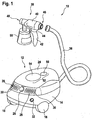
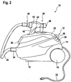
- the Fig. 1 to 3 show various views of a spray gun system 10 according to an embodiment of the present invention.
- the spray gun system 10 comprises a base device 12 with a housing 14, in which a compressed air generating device, not shown, is received.
- a compressed air generating device not shown
- two wheels 16 are accommodated, so that the base device 12 can be moved in the manner of a vacuum cleaner over a substrate.
- projection-like supports 18 are provided, which together with the wheels 16 form the bearing surface of the housing 14, as best in Fig. 2 can be seen.
- the supports 18 can also be a centrally located, pivotable and thus steerable wheel (not shown) may be arranged on the front underside of the housing 14.
- a switch 26 is provided, which serves for switching on and off of the recorded in the housing 14 of the base device 12 compressed air generating device and for controlling the compressed air generated by this device.
- the switch 26 is designed here as a pressure switch. Turning the switch 26, however, allows the compressed air flow control.
- air channels 28 are provided, via which the compressed air generating device is supplied with the required air.
- air filters not shown, are arranged in each case, which filter the sucked outside air.
- the air channels 28 are covered with grid-like cover members 40, which are held by means of snap-in connections (not shown) releasably on the housing 14 of the base device 12.
- Such latching connections are advantageous in that a user can easily remove the cover elements 30 without the aid of further tools from the housing 14 and mount on this, when the air filter must be replaced.
- the base device 12 For powering the base device 12, it can be connected to a power source by means of a power cord.
- the power cord is wound within the housing 14 on an unillustrated automatic winding device and can be pulled out of the housing 14 as needed.
- the power cord may also be detachably engaged with an electrical terminal disposed on the housing 14 so that it may be separated and stowed away from the housing in the state where it is not needed, preferably in a dedicated space Reception room at the bottom of the housing (not shown).
- a connection 34 In the front region of the housing 14 is a connection 34, to which a free end of a compressed air hose 36 can be detachably connected.
- the spray gun system 10 comprises a spray gun designed as a hand-held device 38 with a housing 40 on which a handle 42 for holding the spray gun 38 is integrally formed.
- a pressure switch 44 is received, which serves to actuate the spray gun 38.
- a port 46 is arranged, to which the other free end of the compressed air hose 36 is connectable.
- a spray nozzle 48 is integrated, via which the sprayed material to be sprayed is discharged.
- the spray nozzle 48 is present in such a way that the user can set different beam shapes and beam directions, with which the spray material leaves the spray nozzle 48.
- a point beam, a beam in the form of a horizontally extending ellipse, a beam in the form of a vertically extending ellipse, or the like can be set.
- a Spritzgutage matterer 50 is releasably held, for example by means of a screw or the like.
- a receiving device 52 in the form of two depressions 54 and 56 is formed in the cover 24 of the base device 12.
- the recess 54 is adapted to the shape of the Spritzgutage mattersers 50 and serves to receive the same
- the recess 56 is adapted to the shape of the handle 42 of the spray gun 38 and serves to receive the same. Accordingly, the spray gun 38 can be used together with the Spritzgutage capableer 50 in the recesses 54 and 56 of the receiving device 52, as in Fig. 2 shown, causing a drop of the components and one with a falling down associated fouling or damaging the same is reliably prevented.
- a fastening device not shown herein can be provided which clamps the components, for example, detent locking or otherwise secured in the receiving device.
- tabs 58 are formed on the underside of the lid 24, which can be accommodated to form a so-called Einsteckscharniers in correspondingly formed recesses 60, which are formed on the upper side of the housing 14. Accordingly, the lid 24 can optionally be opened and closed.
- the housing 14, the lid 24 and the hinges are matched to each other so that the lid can be opened at an angle of more than 90 degrees, preferably about 110 degrees, to ensure easy access to the receiving space 22.
- latching projections 62 and 64 are respectively formed in the front region of the cover 24 and the housing 14, which engage with each other as soon as the cover 24 is pressed onto the housing 14 of the base device 12 ,
- the receiving space 22, which is formed within the housing 14, is such that the spray gun 38 and the compressed air hose 36 together with the Spritzgutage matterser 50 can be stored in this.
Landscapes
- Nozzles (AREA)
Description
- Die vorliegende Erfindung betrifft ein Spritzpistolensystem, umfassend eine Spritzpistole zum Abgeben eines Spritguts, an der ein Spritzgutaufnahmebehälter befestigbar ist; eine Basisvorrichtung mit einem Gehäuse, in dem eine Drucklufterzeugungseinrichtung aufgenommen ist; und einen Druckluftschlauch, der an die Spritzpistole und an die Basisvorrichtung anschließbar ist, um diese miteinander zu verbinden.
- Spritzpistolensysteme der zuvor genannten Art sind im Stand der Technik in verschiedensten Ausgestaltungen bekannt, siehe hierzu beispielsweise
DE-A-10 2005 041 488 ,DE-A-10 2005 006 360 ,WO 01/24941 A US 5 181 832 A undUS 5294 413 A . Mit derartigen Spritzpistolensystemen kann Spritzgut verspritzt werden, insbesondere mit Wasser verdünnbares und lösungsmittelhaltiges Spritzgut, wie beispielsweise Farben, Lacke, Lasuren, Grundierungen, Beizen und Holzschutzmittel, um nur einige zu nennen. Als Spritzverfahren kommt meist das Niederdruck-Spritzverfahren zur Anwendung, bei dem es sich um ein Verfahren handelt, bei dem Spritzgut bei einem geringen Druck von etwa 0,2 bis etwa 0,5 bar und mit einem hohen Luftvolumen ab etwa 200 Liter pro Minute verspritzt wird. Dieses HVLP-Spritzverfahren erreicht wegen des geringen Überspritzens, d.h. wegen seiner geringen Sprühnebelverluste, Beschichtungsgrade bis etwa 65% und ist somit herkömmlichen Verfahren, die Beschichtungsgrade zwischen etwa 20 und etwa 35% erzielen, überlegen. Kennzeichnend für das Verfahren ist der das Spritzgut umgebende Luftkegel, der ein Überspritzen und eine Farbnebelbildung verringert. Damit ergeben sich Vorteile wie Lackeinsparung und geringe Lösungsmittelemissionen, die sich besonders umweltschonend auswirken. - Derartige Spritzpistolensysteme umfassen normalerweise eine Basisvorrichtung mit einem häufig auf Rollen beweglichen Gehäuse, in dem eine Drucklufterzeugungseinrichtung aufgenommen ist, welche die zum Verspritzen des Spritzguts erforderliche Druckluft generiert. Die Drucklufterzeugungseinrichtung der Basisvorrichtung ist über einen Druckluftschlauch mit einer Spritzpistole verbunden, die als Handgerät ausgebildet ist und mit deren Hilfe das Spritzgut aufgetragen werden kann. Die Spritzpistole umfasst ein Gehäuse, an dem ein Handgriff ausgebildet ist, eine Halteeinrichtung zur Aufnahme eines Spritzgutaufnahmebehälters sowie eine Spritzdüse, durch die das Spritzgut unter Druck abgegeben wird.
- Während des Betriebs des Spritzpistolensystems wird der von der Drucklufterzeugungseinheit erzeugte Druckluftstrom durch den Druckluftschlauch in den an der Spritzpistole gehaltenen Spritzgutaufnahmebehälter geleitet. Ein Teil des Druckluftstroms fördert das in dem Spritzgutaufnahmebehälter enthaltene Spritzgut nach Betätigung eines an der Spritzpistole angeordneten Bedienhebels aus dem Spritzgutaufnahmebehälter und wird durch die Spritzdüse abgegeben. Der restliche Teil des Druckluftstroms gelangt über rund um die Spritzdüse verteilte Öffnungen ins Freie, und zwar in Form eines Luftkegels, der das Spritzgut umhüllt. Mit Hilfe dieses Luftkegels wird die Farbnebelbildung wesentlich verringert.
- Während Spritzpausen bzw. während eines Nachfüllens des Spritzgutes muss die Spritzpistole auf einer entsprechenden Unterlage abgestellt werden. Normalerweise bilden der Handgriff der Spritzpistole und der Spritzgutbehälter hierzu gemeinsam eine Abstellfläche, auf der die Spritzpistole auf einem Untergrund abgestellt werden kann. Aufgrund des sperrigen Druckluftschlauches, der an die Spritzpistole angeschlossen ist, besteht jedoch die Gefahr, dass die abgestellte Spritzpistole umkippt. Hierbei kann die Spritzpistole verschmutzt oder beschädigt werden, was es zu vermeiden gilt.
- Ausgehend von diesem Stand der Technik ist es eine Aufgabe der vorliegenden Erfindung, ein Spritzpistolensystem der eingangs genannten Art mit einem alternativen Aufbau zu schaffen, bei dem die genannte Problematik eliminiert wird.
- Zur Lösung dieser Aufgabe schafft die vorliegende Erfindung ein Spritzpistolensystem, umfassend eine Spritzpistole zum Abgeben eines Spritzguts, an der ein Spritzgutaufnahmebehälter befestigbar ist; eine Basisvorrichtung mit einem Gehäuse, in dem eine Drucklufterzeugungseinrichtung aufgenommen ist; und einen Druckluftschlauch, der an die Spritzpistole und an die Basisvorrichtung anschließbar ist, um diese miteinander zu verbinden. Erfindungsgemäß ist an dem Gehäuse der Basisvorrichtung eine Aufnahmeeinrichtung vorgesehen, in welcher die Spritzpistole mit dem daran befestigten Spritzgutaufnahmebehälter aufnehmbar ist. Entsprechend kann die Spritzpistole in Spritzpausen an der Aufnahmeeinrichtung angeordnet werden, die ein Umkippen und ein damit einhergehendes Verschmutzen oder Beschädigen der Spritzpistole sicher verhindert.
- Die Aufnahmeeinrichtung weist zumindest eine Vertiefung auf, in der die Spritzpistole mit dem daran gehaltenen Spritzgutaufnahmebehälter zumindest teilweise aufnehmbar ist, so dass ein Umkippen der Spritzpistole verhindert wird. Erfindungsgemäß weist die Aufnahmeeinrichtung auch eine erste Vertiefung zur zumindest teilweisen Aufnahme der Spritzpistole und eine zweite Vertiefung zur zumindest teilweisen Aufnahme des daran befestigten Spritzgutaufnahmebehälters auf. Dabei ist die Form der Vertiefung vorteilhaft derart an die aufzunehmenden Bereiche der Spritzpistole und des Spritzgutaufnahmebehälters angepasst, dass ein Umkippen der in der Aufnahmeeinrichtung aufgenommenen Komponenten sicher verhindert wird. Derartige Vertiefungen sind dahingehend vorteilhaft, dass sie einfach und preiswert herzustellen sind.
- Die Aufnahmeeinrichtung ist bevorzugt an der während des Betriebs des Spritzpistolensystems aufwärts weisenden Seite des Gehäuses der Basisvorrichtung vorgesehen, so dass die Aufnähmeeinrichtung für den Benutzer stets problemlos zugänglich ist.
- Die Aufnahmeeinrichtung ist an der Außenseite des Deckels des Gehäuses der Basisvorrichtung vorgesehen. Der Deckel ist derart ausgebildet, dass er einen in dem Gehäuse ausgebildeten Aufnahmeraum wahlweise abdeckt oder freigibt. In einem solchen Aufnahmeraum können Komponenten des Spritzpistolensystems, wie beispielsweise die Spritzpistole, der Spritzgutaufnahmebehälter und der Druckluftschlauch, verstaut werden, wenn sich das Spritzpistolensystem nicht im Einsatz befindet. Vorteilhaft ist ferner zumindest eine Scharnierverbindung und/oder zumindest eine Rastverbindung zum wahlweisen Öffnen oder Schließen des Deckels und/oder zum Befestigen des Deckels an dem Gehäuse vorgesehen.
- Die Scharnierverbindung umfasst bevorzugt zumindest ein Einsteckscharnier. Derartige Einsteckscharniere zeichnen sich dadurch aus, dass sie einfach herstellbar sind. Zudem können sie einteilig mit Deckel und Gehäuse ausgebildet werden, weshalb keine zusätzlichen Bauteile zur Erzeugung der Scharnierverbindung erforderlich sind.
- Das Gehäuse, der Deckel und die Scharnierverbindung sind vorteilhaft derart aufeinander abgestimmt, dass sich der Deckel in einem Winkel von mehr als 90 Grad öffnen lässt, besser noch in einem Winkel von etwa 110 Grad, um einen bequemen Zugang zu dem im Gehäuse ausgebildeten Aufnahmeraum zu gewährleisten.
- Bevorzugt ist ferner eine Befestigungseinrichtung vorgesehen, die derart beschaffen ist, dass sie die in der Aufnahmeeinrichtung gehaltene Spritzpistole mit dem daran befestigten Spritzgutaufnahmebehälter in der Aufnahmeeinrichtung vor einem Herausfallen sichert. Entsprechend kann das Gehäuse der Basisvorrichtung auch dann problemlos bewegt oder gekippt werden, wenn die Spritzpistole und der Spritzgutaufnahmebehälter in der Aufnahmevorrichtung aufgenommen sind. Bei der Befestigungseinrichtung kann es sich beispielsweise um eine solche handeln, die eine Rastverbindung, eine Klemmverbindung oder dergleichen erzeugt.
- Nachfolgend wird eine beispielhafte Ausführungsform der vorliegenden Erfindung unter Bezugnahme auf die beiliegenden Zeichnungen genauer beschrieben. Darin ist:
- Fig. 1
- eine perspektivische Ansicht, die ein Spritzpistolensystem gemäß einer Ausführungsform der vorliegenden Erfindung zeigt;
- Fig. 2
- eine Seitenansicht des in
Fig. 1 dargestellten Spritzpistolensystems; und - Fig. 3
- eine perspektivische Teilansicht des in den
Fig. 1 und2 dargestellten Spritzpistolensystems. - Gleiche Bezugsziffern beziehen sich nachfolgend auf gleiche Bauteile.
- Die
Fig. 1 bis 3 zeigen verschiedene Ansichten eines Spritzpistolensystems 10 gemäß einer Ausführungsform der vorliegenden Erfindung. Das Spritzpistolensystem 10 umfasst eine Basisvorrichtung 12 mit einem Gehäuse 14, in dem eine nicht dargestellte Drucklufterzeugungseinrichtung aufgenommen ist. An der hinteren Unterseite des Gehäuses 14 sind zwei Räder 16 aufgenommen, so dass die Basisvorrichtung 12 nach Art eines Staubsaugers über einen Untergrund bewegt werden kann. An der vorderen Unterseite des Gehäuses 14 sind vorsprungartige Stützen 18 vorgesehen, die zusammen mit den Rädern 16 die Auflagefläche des Gehäuses 14 bilden, wie es am besten inFig. 2 zu erkennen ist. Anstelle der Stützen 18 kann auch ein mittig angeordnetes, verschwenkbares und somit lenkbares Rad (nicht gezeigt) an der vorderen Unterseite des Gehäuses 14 angeordnet sein. In dem Gehäuse 14 ist ein über eine obere Öffnung 20 für den Benutzer zugänglicher Aufnahmeraum 22 ausgebildet, der mit einem Deckel 24 verschließbar ist. Am hinteren Gehäusebereich ist ein Schalter 26 vorgesehen, der zum Ein- und Ausschalten der in dem Gehäuse 14 der Basisvorrichtung 12 aufgenommenen Drucklufterzeugungseinrichtung sowie zum Regeln der von dieser Einrichtung erzeugten Druckluft dient. Zum Ein- und Ausschalten der Drucklufterzeugungseinrichtung ist der Schalter 26 vorliegend als Druckschalter ausgebildet. Ein Drehen des Schalters 26 ermöglicht hingegen die Druckluftmengenregelung. Neben dem Schalter 26 sind Luftkanäle 28 vorgesehen, über welche die Drucklufterzeugungseinrichtung mit der erforderlichen Luft versorgt wird. In den Luftkanälen 28 sind jeweils nicht dargestellte Luftfilter angeordnet, welche die angesaugte Außenluft filtern. Die Luftkanäle 28 sind mit gitterartig ausgebildeten Abdeckelementen 40 abgedeckt, die mit Hilfe von Rastverbindungen (nicht dargestellt) lösbar an dem Gehäuse 14 der Basisvorrichtung 12 gehalten sind. Derartige Rastverbindungen sind dahingehend von Vorteil, dass ein Benutzer die Abdeckelemente 30 ohne Zuhilfenahme weiterer Werkzeuge problemlos von dem Gehäuse 14 entfernen und an diesem montieren kann, wenn die Luftfilter ausgetauscht werden müssen. Zur Energieversorgung der Basisvorrichtung 12 -kann diese mit Hilfe eines Netzkabels mit einer Stromquelle verbunden werden. Das Netzkabel ist innerhalb des Gehäuses 14 auf eine nicht dargestellte automatische Aufwickelvorrichtung aufgewickelt und kann bei Bedarf aus dem Gehäuse 14 gezogen werden. Alternativ kann das Netzkabel aber auch lösbar mit einem an dem Gehäuse 14 angeordneten elektrischen Anschluss in Eingriff gebracht werden, so dass es in demjenigen Zustand, in dem es nicht benötigt wird, von dem Gehäuse getrennt und verstaut werden kann, bevorzugt in einem extra hierfür vorgesehenen Aufnahmeraum an der Unterseite des Gehäuses (nicht gezeigt). Im vorderen Bereich des Gehäuses 14 ist ein Anschluss 34 angeordnet, an den ein freies Ende eines Druckluftschlauchs 36 lösbar angeschlossen werden kann. - Ferner umfasst das Spritzpistolensystem 10 eine als Handgerät ausgebildete Spritzpistole 38 mit einem Gehäuse 40, an dem einteilig ein Handgriff 42 zum Halten der Spritzpistole 38 ausgebildet ist. Im oberen Bereich des Handgriffes 42 ist ein Druckschalter 44 aufgenommen, der zum Betätigen der Spritzpistole 38 dient. Am hinteren oberen Ende des Gehäuses 40 der Spritzpistole 38 ist ein Anschluss 46 angeordnet, an den das andere freie Ende des Druckluftschlauches 36 anschließbar ist. Im vorderen Bereich des Gehäuses 40 der Spritzpistole 38 ist eine Spritzdüse 48 integriert, über die das zu sprühende Spritzgut abgegeben wird. Die Spritzdüse 48 ist vorliegend derart beschaffen, dass der Benutzer unterschiedliche Strahlformen und Strahlrichtungen einstellen kann, mit denen das Spritzgut die Spritzdüse 48 verlässt. So können beispielsweise ein punktförmiger Strahl, ein Strahl in Form einer sich horizontal erstreckenden Ellipse, ein Strahl in Form einer sich vertikal erstreckenden Ellipse oder dergleichen eingestellt werden. Am vorderen unteren Bereich des Gehäuses 40 ist ein Spritzgutaufnahmebehälter 50 lösbar gehalten, beispielsweise mit Hilfe einer Schraubverbindung oder dergleichen.
- Um die Spritzpistole 38 mit dem daran gehaltenen Spritzgutaufnahmebehälter 50 während Spritzpausen abstellen zu können, ist in dem Deckel 24 der Basisvorrichtung 12 eine Aufnahmeeinrichtung 52 in Form von zwei Vertiefungen 54 und 56 ausgebildet. Die Vertiefung 54 ist an die Form des Spritzgutaufnahmebehälters 50 angepasst und dient zur Aufnahme derselben, und die Vertiefung 56 ist an die Form des Handgriffes 42 der Spritzpistole 38 angepasst und dient zur Aufnahme desselben. Entsprechend kann die Spritzpistole 38 zusammen mit dem Spritzgutaufnahmebehälter 50 in die Vertiefungen 54 und 56 der Aufnahmeeinrichtung 52 eingesetzt werden, wie es in
Fig. 2 gezeigt ist, wodurch ein Umfallen der Komponenten und ein mit einem Umfallen einhergehendes Verschmutzen oder Beschädigen derselben sicher verhindert wird. Um die Komponenten in der Aufnahmeeinrichtung 52 vor einem Herausfallen zu sichern, kann zudem eine vorliegend nicht dargestellte Befestigungseinrichtung vorgesehen werden, welche die Komponenten beispielsweise klemmen, rastend oder in anderer Art und Weise in der Aufnahmeeinrichtung sichert. - Wie es in
Fig. 3 dargestellt ist, sind an der Unterseite des Deckels 24 Laschen 58 ausgebildet, die zur Ausbildung eines so genannten Einsteckscharniers in entsprechend ausgebildete Aussparungen 60 aufnehmbar sind, die an der Oberseite des Gehäuses 14 ausgebildet sind. Entsprechend kann der Deckel 24 wahlweise auf- und zugeklappt werden. Das Gehäuse 14, der Deckel 24 und die Scharniere sind derart aufeinander abgestimmt, dass der Deckel in einem Winkel von mehr als 90 Grad geöffnet werden kann, bevorzugt etwa 110 Grad, um einen problemlosen Zugang zum Aufnahmeraum 22 zu gewährleisten. Um den Deckel 24 fest an dem Gehäuse 14 anordnen zu können, sind im vorderen Bereich des Deckels 24 und des Gehäuses 14 jeweils Rastvorsprünge 62 und 64 ausgebildet, die miteinander in Eingriff kommen, sobald der Deckel 24 auf das Gehäuse 14 der Basisvorrichtung 12 gedrückt wird. - Der Aufnahmeraum 22, der innerhalb des Gehäuses 14 ausgebildet ist, ist derart beschaffen, dass die Spritzpistole 38 und der Druckluftschlauch 36 zusammen mit dem Spritzgutaufnahmebehälter 50 in diesem verstaut werden können.
- Es sollte klar sein, dass die zuvor beschriebene Ausführungsform des erfindungsgemäßen Spritzpistolensystems nur als Beispiel dient und in keinerlei Hinsicht einschränkend ist.
Claims (6)
- Spritzpistotensystem (10), umfassend eine Spritzpistole (38) zum Abgeben eines Spritzguts, an der ein Spritzgutaufnahmebehälter (50) befestigbar ist; eine Basisvorrichtung (12) mit einem Gehäuse (14), in dem eine Drucklufterzeugungseinrichtung aufgenommen ist, und mit einem Deckel (24), der derart ausgebildet ist, dass er einen in dem Gehäuse (14) ausgebildeten Aufnahmeraum (22) wahlweise abdeckt oder freigibt, der zur Aufnahme von Komponenten (36, 38, 50) des Spritzpistolensystems (10) dient und einen Druckluftschlauch (36), der an die Spritzpistole (38) und an die Basisvorrichtung (12) anschließbar ist, um diese miteinander zu verbinden, wobei an dem Gehäuse (14) der Basisvorrichtung (12) eine Aufnahmeeinrichtung (52) zur Aufnahme der Spritzpistole (38) mit dem daran befestigten Spritzgutaufnahmebehälter (50) vorgesehen ist, wobei die Aufnahmeeinrichtung (52) an der Außenseite des Deckels (24) vorgesehen ist und zumindest eine Vertiefung (54, 56) aufweist, in der die Spritzpistole (38) mit dem an dieser befestigten Spritzgutaufnahmebehälter (50) zumindest teilweise aufnehmbar ist, dadurch gekennzeichnet, dass die Aufnahmeeinrichtung (52) eine erste Vertiefung (56) zur zumindest teilweisen Aufnahme der Spritzpistole (38) und eine zweite Vertiefung (54) zur zumindest teilweisen Aufnahme des an dieser befestigten Spritzgutaufnahmebehälters (50) aufweist.
- Spritzpistolensystem (10) nach Anspruch 1, dadurch gekennzeichnet, dass die Aufnahmeeinrichtung (52) an der während des Betriebs des Spritzpistolensystems (10) aufwärts weisenden Seite des Gehäuses (14) der Basisvorrichtung (12) vorgesehen ist.
- Spritzpistolensystem (10) nach einem der vorhergehenden Ansprüche, dadurch gekennzeichnet, dass zumindest eine Scharnierverbindung (58, 60) und/oder zumindest eine Rastverbindung (62, 64) zum Befestigen des Deckels (24) an dem Gehäuse (14) vorgesehen ist.
- Spritzpistolensystem (10) nach Anspruch 3, dadurch gekennzeichnet, dass die Scharnierverbindung (58, 60) zumindest ein Einsteckschamier aufweist.
- Spritzpistolensystem (10) nach Anspruch 3 oder 4, dadurch gekennzeichnet, dass das Gehäuse (14), der Deckel (24) und die Scharnierverbindung (58, 60) derart aufeinander abgestimmt sind, dass sich der Deckel (24) in einem Winkel von mehr als 90 Grad öffnen lässt.
- Spritzpistolensystem (10) nach einem der vorhergehenden Ansprüche, dadurch gekennzeichnet, dass eine Befestigungseinrichtung vorgesehen ist, die derart beschaffen ist, dass sie die in der Aufnahmeeinrichtung (52) gehaltene Spritzpistole (38) mit dem daran befestigten Spritzgutaufnahmebehälter (50) in der Aufnahmeeinrichtung (52) vor einem Herausfallen sichert.
Applications Claiming Priority (2)
| Application Number | Priority Date | Filing Date | Title |
|---|---|---|---|
| DE200810000394 DE102008000394A1 (de) | 2008-02-25 | 2008-02-25 | Spritzpistolensystem |
| PCT/EP2009/052033 WO2009106485A1 (de) | 2008-02-25 | 2009-02-20 | Spritzpistolensystem |
Publications (2)
| Publication Number | Publication Date |
|---|---|
| EP2257384A1 EP2257384A1 (de) | 2010-12-08 |
| EP2257384B1 true EP2257384B1 (de) | 2016-05-11 |
Family
ID=40669115
Family Applications (1)
| Application Number | Title | Priority Date | Filing Date |
|---|---|---|---|
| EP09715863.8A Not-in-force EP2257384B1 (de) | 2008-02-25 | 2009-02-20 | Spritzpistolensystem |
Country Status (6)
| Country | Link |
|---|---|
| EP (1) | EP2257384B1 (de) |
| CN (1) | CN101952044B (de) |
| DE (1) | DE102008000394A1 (de) |
| ES (1) | ES2586438T3 (de) |
| RU (1) | RU2491996C2 (de) |
| WO (1) | WO2009106485A1 (de) |
Families Citing this family (2)
| Publication number | Priority date | Publication date | Assignee | Title |
|---|---|---|---|---|
| RU2712570C1 (ru) * | 2019-04-09 | 2020-01-29 | Федеральное государственное бюджетное образовательное учреждение высшего образования "Волгоградский государственный технический университет" (ВолгГТУ) | Распылительная система |
| RU2740917C1 (ru) * | 2020-04-23 | 2021-01-21 | Федеральное государственное бюджетное образовательное учреждение высшего образования "Волгоградский государственный технический университет" (ВолгГТУ) | Распылительная система |
Citations (2)
| Publication number | Priority date | Publication date | Assignee | Title |
|---|---|---|---|---|
| US5181832A (en) * | 1991-07-30 | 1993-01-26 | Wagner Spray Tech Corporation | Fan motor and air hose storage housing for portable spray paint guns |
| US5294413A (en) * | 1991-07-17 | 1994-03-15 | Hu-Friedy Mfg. Co., Inc. | Sterilization and storage cassette |
Family Cites Families (22)
| Publication number | Priority date | Publication date | Assignee | Title |
|---|---|---|---|---|
| SU749440A1 (ru) * | 1978-05-03 | 1980-07-23 | Ордена Красной Звезды Автобаза Министерства Обороны Ссср | Установка дл нанесени антикоррозийных покрытий |
| US4389166A (en) * | 1979-10-22 | 1983-06-21 | Harvey-Westbury Corp. | Self-contained portable air compressor |
| US4545534A (en) * | 1983-08-08 | 1985-10-08 | Schaefer Gerald O | Air brush organizer |
| US4998698A (en) * | 1989-12-29 | 1991-03-12 | Martinson Jon P | Glue gun holder apparatus |
| DE4000012A1 (de) * | 1990-01-02 | 1990-07-12 | Bernhard Clemens Kellermann | Halterung fuer spritzpistolen, insbesondere fuer air brush pistolen, mit regulierbarer duesenspitzenbefeuchtung |
| JP2736958B2 (ja) * | 1994-06-28 | 1998-04-08 | 株式会社シー・アイ・シー | エアゾール支持装置 |
| EP0720870A3 (de) * | 1995-01-03 | 1999-03-03 | Ransburg Corporation | Halterung für eine Spritzpistole |
| DE29619172U1 (de) * | 1996-11-05 | 1997-04-10 | Meiling, Uwe, 06179 Langenbogen | Vorrichtung zur Anwendung beim manuellen Farbspritzen |
| CN2304344Y (zh) * | 1997-09-08 | 1999-01-20 | 伸兴工业股份有限公司 | 一种吸尘器 |
| US6189809B1 (en) * | 1999-09-23 | 2001-02-20 | Illinois Tool Works Inc. | Multi-feed spray gun |
| AUPQ324899A0 (en) * | 1999-10-05 | 1999-10-28 | Mi-Ok Pty Ltd | Portable air-powered tools |
| GB0210446D0 (en) * | 2002-05-08 | 2002-06-12 | 3M Innovative Properties Co | Conformable pouch reservoir for spray gun |
| US6892957B2 (en) * | 2002-08-29 | 2005-05-17 | Black & Decker Inc. | Pressure washer with improved mobility |
| GB0224698D0 (en) * | 2002-10-24 | 2002-12-04 | 3M Innovative Properties Co | Easy clean spray gun |
| JP4233901B2 (ja) * | 2003-03-19 | 2009-03-04 | トヨタ紡織株式会社 | 塗装装置及びスプレーガン |
| DE20317558U1 (de) * | 2003-11-12 | 2004-02-12 | Fiber-Tech Construction Gmbh | Lösch- und Rettungsfahrzeug für schwer zugängliche Einsatzorte |
| DE20317866U1 (de) * | 2003-11-19 | 2004-02-12 | Fritz Schäfer GmbH | Behälter mit schwenkbar angelenktem Deckel |
| RU39287U1 (ru) * | 2004-04-16 | 2004-07-27 | Смирнов Валерий Алексеевич | Пистолет-распылитель |
| CN1698516A (zh) * | 2004-05-19 | 2005-11-23 | 乐金电子(天津)电器有限公司 | 真空吸尘器的配件罩盖安装结构 |
| EP1611959B1 (de) * | 2004-07-02 | 2006-09-20 | Flexi-Cup | Flexibler Farbbehälter |
| DE102005006360A1 (de) * | 2005-02-11 | 2006-08-24 | Robert Bosch Gmbh | Spritzpistole |
| DE102005041488A1 (de) * | 2005-09-01 | 2007-03-08 | Robert Bosch Gmbh | Druckluftbetriebene Spritzpistole |
-
2008
- 2008-02-25 DE DE200810000394 patent/DE102008000394A1/de not_active Withdrawn
-
2009
- 2009-02-20 CN CN200980106261.9A patent/CN101952044B/zh not_active Expired - Fee Related
- 2009-02-20 EP EP09715863.8A patent/EP2257384B1/de not_active Not-in-force
- 2009-02-20 WO PCT/EP2009/052033 patent/WO2009106485A1/de not_active Ceased
- 2009-02-20 ES ES09715863.8T patent/ES2586438T3/es active Active
- 2009-02-20 RU RU2010139295/05A patent/RU2491996C2/ru not_active IP Right Cessation
Patent Citations (2)
| Publication number | Priority date | Publication date | Assignee | Title |
|---|---|---|---|---|
| US5294413A (en) * | 1991-07-17 | 1994-03-15 | Hu-Friedy Mfg. Co., Inc. | Sterilization and storage cassette |
| US5181832A (en) * | 1991-07-30 | 1993-01-26 | Wagner Spray Tech Corporation | Fan motor and air hose storage housing for portable spray paint guns |
Also Published As
| Publication number | Publication date |
|---|---|
| CN101952044B (zh) | 2014-03-05 |
| WO2009106485A1 (de) | 2009-09-03 |
| RU2491996C2 (ru) | 2013-09-10 |
| CN101952044A (zh) | 2011-01-19 |
| EP2257384A1 (de) | 2010-12-08 |
| DE102008000394A1 (de) | 2009-08-27 |
| ES2586438T3 (es) | 2016-10-14 |
| RU2010139295A (ru) | 2012-04-10 |
Similar Documents
| Publication | Publication Date | Title |
|---|---|---|
| EP2092987B1 (de) | Spritzpistolensystem | |
| EP2106298B1 (de) | Reinigungsvorrichtung zur reinigung von spritzpistolen | |
| DE20208915U1 (de) | Farbsprühgerät | |
| EP3597304A1 (de) | Ausgabevorrichtung zum versprühen eines sprühfähigen fluides | |
| EP1886938B1 (de) | Sprühkopf und Vorrichtung zur Ausgabe einer Flüssigkeit | |
| DE102004022131A1 (de) | Sprühkopf zum Atomisieren eines Mediums | |
| DE2446533A1 (de) | Mit druckluft zu betreibende spritzpistole | |
| EP2257381B1 (de) | Spritzpistolensystem | |
| EP2257388B1 (de) | Spritzpistole | |
| EP2257384A1 (de) | Spritzpistolensystem | |
| EP2257385B1 (de) | Spritzpistolensystem | |
| WO2011154183A1 (de) | Farbauftragsystem | |
| EP2257387B1 (de) | Spritzpistole mit einer verlängerungseinrichtung zur verlängerung des handgriffs der spritzpistole | |
| DE102008000400A1 (de) | Transportables Farbspritzgerät | |
| EP2257383A1 (de) | Spritzpistole | |
| DE202013101137U1 (de) | Vorrichtung zum Begrenzen des Nadelhubs bei einem Spritzgerät, insbesondere einer Spritzpistole und Spritzgerät, insbesondere Spritzpistole mit einer solchen Vorrichtung | |
| DE8613576U1 (de) | Fassadenreiniger | |
| DE202023101964U1 (de) | Verbesserte Sprühauftragevorrichtung | |
| DE3130730A1 (de) | Vorrichtung zum lackieren von technischen gegenstaenden | |
| DE10355952A1 (de) | Vorrichtung zum Reinigen einer Farbrolle | |
| DE202007015166U1 (de) | Reinigungsvorrichtung zur Reinigung von Spritzpistolen | |
| DE202004009072U1 (de) | Sprühkopf zum Atomisieren eines Mediums | |
| DE9202921U1 (de) | Spritzanlage für den ein- oder mehrfachen Anschluß einer Spritzpistole | |
| DE202013004958U1 (de) | Mehrkammer-Aerosolsprühvorrichtung | |
| DE29516742U1 (de) | Vorrichtung zum Auftragen von flüssigen Medien |
Legal Events
| Date | Code | Title | Description |
|---|---|---|---|
| PUAI | Public reference made under article 153(3) epc to a published international application that has entered the european phase |
Free format text: ORIGINAL CODE: 0009012 |
|
| 17P | Request for examination filed |
Effective date: 20100927 |
|
| AK | Designated contracting states |
Kind code of ref document: A1 Designated state(s): AT BE BG CH CY CZ DE DK EE ES FI FR GB GR HR HU IE IS IT LI LT LU LV MC MK MT NL NO PL PT RO SE SI SK TR |
|
| AX | Request for extension of the european patent |
Extension state: AL BA RS |
|
| DAX | Request for extension of the european patent (deleted) | ||
| 17Q | First examination report despatched |
Effective date: 20150326 |
|
| GRAP | Despatch of communication of intention to grant a patent |
Free format text: ORIGINAL CODE: EPIDOSNIGR1 |
|
| INTG | Intention to grant announced |
Effective date: 20160216 |
|
| GRAS | Grant fee paid |
Free format text: ORIGINAL CODE: EPIDOSNIGR3 |
|
| GRAA | (expected) grant |
Free format text: ORIGINAL CODE: 0009210 |
|
| AK | Designated contracting states |
Kind code of ref document: B1 Designated state(s): AT BE BG CH CY CZ DE DK EE ES FI FR GB GR HR HU IE IS IT LI LT LU LV MC MK MT NL NO PL PT RO SE SI SK TR |
|
| REG | Reference to a national code |
Ref country code: GB Ref legal event code: FG4D Free format text: NOT ENGLISH |
|
| REG | Reference to a national code |
Ref country code: CH Ref legal event code: EP |
|
| REG | Reference to a national code |
Ref country code: AT Ref legal event code: REF Ref document number: 798213 Country of ref document: AT Kind code of ref document: T Effective date: 20160515 |
|
| REG | Reference to a national code |
Ref country code: IE Ref legal event code: FG4D Free format text: LANGUAGE OF EP DOCUMENT: GERMAN |
|
| REG | Reference to a national code |
Ref country code: DE Ref legal event code: R096 Ref document number: 502009012562 Country of ref document: DE |
|
| REG | Reference to a national code |
Ref country code: LT Ref legal event code: MG4D |
|
| REG | Reference to a national code |
Ref country code: NL Ref legal event code: MP Effective date: 20160511 |
|
| REG | Reference to a national code |
Ref country code: ES Ref legal event code: FG2A Ref document number: 2586438 Country of ref document: ES Kind code of ref document: T3 Effective date: 20161014 |
|
| PG25 | Lapsed in a contracting state [announced via postgrant information from national office to epo] |
Ref country code: NO Free format text: LAPSE BECAUSE OF FAILURE TO SUBMIT A TRANSLATION OF THE DESCRIPTION OR TO PAY THE FEE WITHIN THE PRESCRIBED TIME-LIMIT Effective date: 20160811 Ref country code: NL Free format text: LAPSE BECAUSE OF FAILURE TO SUBMIT A TRANSLATION OF THE DESCRIPTION OR TO PAY THE FEE WITHIN THE PRESCRIBED TIME-LIMIT Effective date: 20160511 Ref country code: LT Free format text: LAPSE BECAUSE OF FAILURE TO SUBMIT A TRANSLATION OF THE DESCRIPTION OR TO PAY THE FEE WITHIN THE PRESCRIBED TIME-LIMIT Effective date: 20160511 Ref country code: FI Free format text: LAPSE BECAUSE OF FAILURE TO SUBMIT A TRANSLATION OF THE DESCRIPTION OR TO PAY THE FEE WITHIN THE PRESCRIBED TIME-LIMIT Effective date: 20160511 |
|
| PG25 | Lapsed in a contracting state [announced via postgrant information from national office to epo] |
Ref country code: PT Free format text: LAPSE BECAUSE OF FAILURE TO SUBMIT A TRANSLATION OF THE DESCRIPTION OR TO PAY THE FEE WITHIN THE PRESCRIBED TIME-LIMIT Effective date: 20160912 Ref country code: LV Free format text: LAPSE BECAUSE OF FAILURE TO SUBMIT A TRANSLATION OF THE DESCRIPTION OR TO PAY THE FEE WITHIN THE PRESCRIBED TIME-LIMIT Effective date: 20160511 Ref country code: SE Free format text: LAPSE BECAUSE OF FAILURE TO SUBMIT A TRANSLATION OF THE DESCRIPTION OR TO PAY THE FEE WITHIN THE PRESCRIBED TIME-LIMIT Effective date: 20160511 Ref country code: GR Free format text: LAPSE BECAUSE OF FAILURE TO SUBMIT A TRANSLATION OF THE DESCRIPTION OR TO PAY THE FEE WITHIN THE PRESCRIBED TIME-LIMIT Effective date: 20160812 Ref country code: HR Free format text: LAPSE BECAUSE OF FAILURE TO SUBMIT A TRANSLATION OF THE DESCRIPTION OR TO PAY THE FEE WITHIN THE PRESCRIBED TIME-LIMIT Effective date: 20160511 |
|
| PG25 | Lapsed in a contracting state [announced via postgrant information from national office to epo] |
Ref country code: IT Free format text: LAPSE BECAUSE OF FAILURE TO SUBMIT A TRANSLATION OF THE DESCRIPTION OR TO PAY THE FEE WITHIN THE PRESCRIBED TIME-LIMIT Effective date: 20160511 |
|
| PG25 | Lapsed in a contracting state [announced via postgrant information from national office to epo] |
Ref country code: DK Free format text: LAPSE BECAUSE OF FAILURE TO SUBMIT A TRANSLATION OF THE DESCRIPTION OR TO PAY THE FEE WITHIN THE PRESCRIBED TIME-LIMIT Effective date: 20160511 Ref country code: RO Free format text: LAPSE BECAUSE OF FAILURE TO SUBMIT A TRANSLATION OF THE DESCRIPTION OR TO PAY THE FEE WITHIN THE PRESCRIBED TIME-LIMIT Effective date: 20160511 Ref country code: SK Free format text: LAPSE BECAUSE OF FAILURE TO SUBMIT A TRANSLATION OF THE DESCRIPTION OR TO PAY THE FEE WITHIN THE PRESCRIBED TIME-LIMIT Effective date: 20160511 Ref country code: CZ Free format text: LAPSE BECAUSE OF FAILURE TO SUBMIT A TRANSLATION OF THE DESCRIPTION OR TO PAY THE FEE WITHIN THE PRESCRIBED TIME-LIMIT Effective date: 20160511 Ref country code: EE Free format text: LAPSE BECAUSE OF FAILURE TO SUBMIT A TRANSLATION OF THE DESCRIPTION OR TO PAY THE FEE WITHIN THE PRESCRIBED TIME-LIMIT Effective date: 20160511 |
|
| REG | Reference to a national code |
Ref country code: DE Ref legal event code: R097 Ref document number: 502009012562 Country of ref document: DE |
|
| PG25 | Lapsed in a contracting state [announced via postgrant information from national office to epo] |
Ref country code: PL Free format text: LAPSE BECAUSE OF FAILURE TO SUBMIT A TRANSLATION OF THE DESCRIPTION OR TO PAY THE FEE WITHIN THE PRESCRIBED TIME-LIMIT Effective date: 20160511 |
|
| PLBE | No opposition filed within time limit |
Free format text: ORIGINAL CODE: 0009261 |
|
| STAA | Information on the status of an ep patent application or granted ep patent |
Free format text: STATUS: NO OPPOSITION FILED WITHIN TIME LIMIT |
|
| 26N | No opposition filed |
Effective date: 20170214 |
|
| PG25 | Lapsed in a contracting state [announced via postgrant information from national office to epo] |
Ref country code: BE Free format text: LAPSE BECAUSE OF NON-PAYMENT OF DUE FEES Effective date: 20170228 Ref country code: SI Free format text: LAPSE BECAUSE OF FAILURE TO SUBMIT A TRANSLATION OF THE DESCRIPTION OR TO PAY THE FEE WITHIN THE PRESCRIBED TIME-LIMIT Effective date: 20160511 |
|
| PG25 | Lapsed in a contracting state [announced via postgrant information from national office to epo] |
Ref country code: MC Free format text: LAPSE BECAUSE OF FAILURE TO SUBMIT A TRANSLATION OF THE DESCRIPTION OR TO PAY THE FEE WITHIN THE PRESCRIBED TIME-LIMIT Effective date: 20160511 |
|
| REG | Reference to a national code |
Ref country code: CH Ref legal event code: PL |
|
| PG25 | Lapsed in a contracting state [announced via postgrant information from national office to epo] |
Ref country code: CH Free format text: LAPSE BECAUSE OF NON-PAYMENT OF DUE FEES Effective date: 20170228 Ref country code: LI Free format text: LAPSE BECAUSE OF NON-PAYMENT OF DUE FEES Effective date: 20170228 |
|
| REG | Reference to a national code |
Ref country code: IE Ref legal event code: MM4A |
|
| REG | Reference to a national code |
Ref country code: FR Ref legal event code: ST Effective date: 20171031 |
|
| PG25 | Lapsed in a contracting state [announced via postgrant information from national office to epo] |
Ref country code: LU Free format text: LAPSE BECAUSE OF NON-PAYMENT OF DUE FEES Effective date: 20170220 |
|
| PG25 | Lapsed in a contracting state [announced via postgrant information from national office to epo] |
Ref country code: FR Free format text: LAPSE BECAUSE OF NON-PAYMENT OF DUE FEES Effective date: 20170228 |
|
| REG | Reference to a national code |
Ref country code: BE Ref legal event code: MM Effective date: 20170228 |
|
| PG25 | Lapsed in a contracting state [announced via postgrant information from national office to epo] |
Ref country code: IE Free format text: LAPSE BECAUSE OF NON-PAYMENT OF DUE FEES Effective date: 20170220 |
|
| REG | Reference to a national code |
Ref country code: AT Ref legal event code: MM01 Ref document number: 798213 Country of ref document: AT Kind code of ref document: T Effective date: 20170220 |
|
| PG25 | Lapsed in a contracting state [announced via postgrant information from national office to epo] |
Ref country code: AT Free format text: LAPSE BECAUSE OF NON-PAYMENT OF DUE FEES Effective date: 20170220 |
|
| PG25 | Lapsed in a contracting state [announced via postgrant information from national office to epo] |
Ref country code: MT Free format text: LAPSE BECAUSE OF FAILURE TO SUBMIT A TRANSLATION OF THE DESCRIPTION OR TO PAY THE FEE WITHIN THE PRESCRIBED TIME-LIMIT Effective date: 20160511 |
|
| PGFP | Annual fee paid to national office [announced via postgrant information from national office to epo] |
Ref country code: PL Payment date: 20190122 Year of fee payment: 8 |
|
| PG25 | Lapsed in a contracting state [announced via postgrant information from national office to epo] |
Ref country code: HU Free format text: LAPSE BECAUSE OF FAILURE TO SUBMIT A TRANSLATION OF THE DESCRIPTION OR TO PAY THE FEE WITHIN THE PRESCRIBED TIME-LIMIT; INVALID AB INITIO Effective date: 20090220 |
|
| PG25 | Lapsed in a contracting state [announced via postgrant information from national office to epo] |
Ref country code: BG Free format text: LAPSE BECAUSE OF FAILURE TO SUBMIT A TRANSLATION OF THE DESCRIPTION OR TO PAY THE FEE WITHIN THE PRESCRIBED TIME-LIMIT Effective date: 20160511 |
|
| PG25 | Lapsed in a contracting state [announced via postgrant information from national office to epo] |
Ref country code: CY Free format text: LAPSE BECAUSE OF NON-PAYMENT OF DUE FEES Effective date: 20160511 |
|
| PG25 | Lapsed in a contracting state [announced via postgrant information from national office to epo] |
Ref country code: MK Free format text: LAPSE BECAUSE OF FAILURE TO SUBMIT A TRANSLATION OF THE DESCRIPTION OR TO PAY THE FEE WITHIN THE PRESCRIBED TIME-LIMIT Effective date: 20160511 |
|
| PG25 | Lapsed in a contracting state [announced via postgrant information from national office to epo] |
Ref country code: TR Free format text: LAPSE BECAUSE OF FAILURE TO SUBMIT A TRANSLATION OF THE DESCRIPTION OR TO PAY THE FEE WITHIN THE PRESCRIBED TIME-LIMIT Effective date: 20160511 |
|
| PGFP | Annual fee paid to national office [announced via postgrant information from national office to epo] |
Ref country code: GB Payment date: 20200225 Year of fee payment: 12 |
|
| PG25 | Lapsed in a contracting state [announced via postgrant information from national office to epo] |
Ref country code: IS Free format text: LAPSE BECAUSE OF FAILURE TO SUBMIT A TRANSLATION OF THE DESCRIPTION OR TO PAY THE FEE WITHIN THE PRESCRIBED TIME-LIMIT Effective date: 20160911 |
|
| REG | Reference to a national code |
Ref country code: ES Ref legal event code: FD2A Effective date: 20210707 |
|
| PGFP | Annual fee paid to national office [announced via postgrant information from national office to epo] |
Ref country code: DE Payment date: 20210420 Year of fee payment: 13 |
|
| GBPC | Gb: european patent ceased through non-payment of renewal fee |
Effective date: 20210220 |
|
| PG25 | Lapsed in a contracting state [announced via postgrant information from national office to epo] |
Ref country code: ES Free format text: LAPSE BECAUSE OF NON-PAYMENT OF DUE FEES Effective date: 20200221 |
|
| PG25 | Lapsed in a contracting state [announced via postgrant information from national office to epo] |
Ref country code: GB Free format text: LAPSE BECAUSE OF NON-PAYMENT OF DUE FEES Effective date: 20210220 |
|
| REG | Reference to a national code |
Ref country code: DE Ref legal event code: R119 Ref document number: 502009012562 Country of ref document: DE |
|
| PG25 | Lapsed in a contracting state [announced via postgrant information from national office to epo] |
Ref country code: DE Free format text: LAPSE BECAUSE OF NON-PAYMENT OF DUE FEES Effective date: 20220901 |