EP2256843A1 - Structure de pile plate, bloc de piles et procédé de fabrication du bloc de piles - Google Patents
Structure de pile plate, bloc de piles et procédé de fabrication du bloc de piles Download PDFInfo
- Publication number
- EP2256843A1 EP2256843A1 EP10173958A EP10173958A EP2256843A1 EP 2256843 A1 EP2256843 A1 EP 2256843A1 EP 10173958 A EP10173958 A EP 10173958A EP 10173958 A EP10173958 A EP 10173958A EP 2256843 A1 EP2256843 A1 EP 2256843A1
- Authority
- EP
- European Patent Office
- Prior art keywords
- frame portion
- circuit board
- board unit
- cap
- tab
- Prior art date
- Legal status (The legal status is an assumption and is not a legal conclusion. Google has not performed a legal analysis and makes no representation as to the accuracy of the status listed.)
- Granted
Links
Images


Classifications
-
- H—ELECTRICITY
- H01—ELECTRIC ELEMENTS
- H01M—PROCESSES OR MEANS, e.g. BATTERIES, FOR THE DIRECT CONVERSION OF CHEMICAL ENERGY INTO ELECTRICAL ENERGY
- H01M50/00—Constructional details or processes of manufacture of the non-active parts of electrochemical cells other than fuel cells, e.g. hybrid cells
- H01M50/10—Primary casings, jackets or wrappings of a single cell or a single battery
- H01M50/102—Primary casings, jackets or wrappings of a single cell or a single battery characterised by their shape or physical structure
- H01M50/103—Primary casings, jackets or wrappings of a single cell or a single battery characterised by their shape or physical structure prismatic or rectangular
-
- H—ELECTRICITY
- H01—ELECTRIC ELEMENTS
- H01M—PROCESSES OR MEANS, e.g. BATTERIES, FOR THE DIRECT CONVERSION OF CHEMICAL ENERGY INTO ELECTRICAL ENERGY
- H01M10/00—Secondary cells; Manufacture thereof
- H01M10/42—Methods or arrangements for servicing or maintenance of secondary cells or secondary half-cells
- H01M10/44—Methods for charging or discharging
- H01M10/443—Methods for charging or discharging in response to temperature
-
- H—ELECTRICITY
- H01—ELECTRIC ELEMENTS
- H01M—PROCESSES OR MEANS, e.g. BATTERIES, FOR THE DIRECT CONVERSION OF CHEMICAL ENERGY INTO ELECTRICAL ENERGY
- H01M50/00—Constructional details or processes of manufacture of the non-active parts of electrochemical cells other than fuel cells, e.g. hybrid cells
- H01M50/10—Primary casings, jackets or wrappings of a single cell or a single battery
- H01M50/147—Lids or covers
-
- H—ELECTRICITY
- H01—ELECTRIC ELEMENTS
- H01M—PROCESSES OR MEANS, e.g. BATTERIES, FOR THE DIRECT CONVERSION OF CHEMICAL ENERGY INTO ELECTRICAL ENERGY
- H01M50/00—Constructional details or processes of manufacture of the non-active parts of electrochemical cells other than fuel cells, e.g. hybrid cells
- H01M50/50—Current conducting connections for cells or batteries
- H01M50/543—Terminals
- H01M50/547—Terminals characterised by the disposition of the terminals on the cells
- H01M50/55—Terminals characterised by the disposition of the terminals on the cells on the same side of the cell
-
- H—ELECTRICITY
- H01—ELECTRIC ELEMENTS
- H01M—PROCESSES OR MEANS, e.g. BATTERIES, FOR THE DIRECT CONVERSION OF CHEMICAL ENERGY INTO ELECTRICAL ENERGY
- H01M10/00—Secondary cells; Manufacture thereof
- H01M10/04—Construction or manufacture in general
- H01M10/0472—Vertically superposed cells with vertically disposed plates
-
- H—ELECTRICITY
- H01—ELECTRIC ELEMENTS
- H01M—PROCESSES OR MEANS, e.g. BATTERIES, FOR THE DIRECT CONVERSION OF CHEMICAL ENERGY INTO ELECTRICAL ENERGY
- H01M2200/00—Safety devices for primary or secondary batteries
- H01M2200/10—Temperature sensitive devices
- H01M2200/106—PTC
-
- Y—GENERAL TAGGING OF NEW TECHNOLOGICAL DEVELOPMENTS; GENERAL TAGGING OF CROSS-SECTIONAL TECHNOLOGIES SPANNING OVER SEVERAL SECTIONS OF THE IPC; TECHNICAL SUBJECTS COVERED BY FORMER USPC CROSS-REFERENCE ART COLLECTIONS [XRACs] AND DIGESTS
- Y02—TECHNOLOGIES OR APPLICATIONS FOR MITIGATION OR ADAPTATION AGAINST CLIMATE CHANGE
- Y02E—REDUCTION OF GREENHOUSE GAS [GHG] EMISSIONS, RELATED TO ENERGY GENERATION, TRANSMISSION OR DISTRIBUTION
- Y02E60/00—Enabling technologies; Technologies with a potential or indirect contribution to GHG emissions mitigation
- Y02E60/10—Energy storage using batteries
-
- Y—GENERAL TAGGING OF NEW TECHNOLOGICAL DEVELOPMENTS; GENERAL TAGGING OF CROSS-SECTIONAL TECHNOLOGIES SPANNING OVER SEVERAL SECTIONS OF THE IPC; TECHNICAL SUBJECTS COVERED BY FORMER USPC CROSS-REFERENCE ART COLLECTIONS [XRACs] AND DIGESTS
- Y02—TECHNOLOGIES OR APPLICATIONS FOR MITIGATION OR ADAPTATION AGAINST CLIMATE CHANGE
- Y02P—CLIMATE CHANGE MITIGATION TECHNOLOGIES IN THE PRODUCTION OR PROCESSING OF GOODS
- Y02P70/00—Climate change mitigation technologies in the production process for final industrial or consumer products
- Y02P70/50—Manufacturing or production processes characterised by the final manufactured product
-
- Y—GENERAL TAGGING OF NEW TECHNOLOGICAL DEVELOPMENTS; GENERAL TAGGING OF CROSS-SECTIONAL TECHNOLOGIES SPANNING OVER SEVERAL SECTIONS OF THE IPC; TECHNICAL SUBJECTS COVERED BY FORMER USPC CROSS-REFERENCE ART COLLECTIONS [XRACs] AND DIGESTS
- Y10—TECHNICAL SUBJECTS COVERED BY FORMER USPC
- Y10T—TECHNICAL SUBJECTS COVERED BY FORMER US CLASSIFICATION
- Y10T29/00—Metal working
- Y10T29/49—Method of mechanical manufacture
- Y10T29/49002—Electrical device making
- Y10T29/49108—Electric battery cell making
- Y10T29/49114—Electric battery cell making including adhesively bonding
Definitions
- the present invention relates to a structure of a thin battery, a battery pack, and method for manufacturing a battery pack, preferred embodiments can be used for a battery of a mobile phone, a game machine, a notebook-type personal computer, or the like.
- a previously proposed battery structure and a battery pack is shown in FIG. 10 .
- a battery pack 101 is constructed of a rectangular battery main body (referred to as a "battery cell” below) 103 containing power generation elements therein, and a circuit board unit 105 on which a plurality of electronic components 104 is mounted to constitute a protection circuit, which are accommodated in a battery case 102 constituted by two halves of a thin box. It is to be noted that, as shown in FIG. 11 , the circuit board unit 105 is supported by ribs 106 formed on the battery case 102 so that the electronic components 104 do not contact the battery cell 103. As shown in FIG.
- the conventional battery pack 101 as described above has, however, the following drawbacks.
- Embodiments of the present invention seek to provide a thinner, smaller and lighter battery pack and reduce the cost by eliminating the need for a battery case constituted by two halves of a thin box.
- Embodiments of the present invention seek to prevent the transfer mold from pressing onto the battery cell, thereby protecting the electronic components.
- Various respective aspects of the present invention are set out in the appended claims.
- Embodiments of the present invention seek to eliminate the need for the conventional two halves of the battery case in such manner that a thin battery is constructed of a battery cell formed in a flat and rectangular shape, a frame portion in which the battery cell is accommodated, a circuit board unit disposed on an outer side surface of the frame portion, a cap portion mounted so as to sandwich the circuit board unit with the outer side surface of the frame portion at one end of the frame portion and the battery cell, and an outer packaging film integrally covering the battery cell and the frame portion, wherein the side surfaces of the battery cell is enclosed by the frame portion, and the front and back surfaces of the battery cell are covered with the outer packaging film.
- areas (wrapped portion), including both the frame portion and the cap portion, where the outer packaging film is wrapped are formed to be thinner relative to a height of an area (not wrapped portion) where the outer packaging film is not wrapped by an amount corresponding to the thickness of the outer packaging film, and at least one of the outer surfaces of the frame portion is formed to be higher than a side surface of the battery cell.
- the thin battery of the first embodiment is formed in such a manner that a cell's positive pole portion fitting window is provided on one side of the frame portion to fit with the cell's positive pole portion projecting from the side surface of the battery cell, and a circuit board unit mounting portion is provided on the outer surface of the side of the frame portion.
- the thin battery of the third embodiment is formed in such a manner that the cap portion has a rectangular end surface portion for sandwiching the circuit board unit mounted on the mounting portion with the frame portion, and a tubular portion which is formed continuously with the rectangular end surface portion and has a fitting portion to be fitted to the outer circumference portion of one ends of the frame portion and the battery cell, and further a hollow portion is provided at one of corner portion formed by the end surface portion and the tubular portion.
- the thin battery of the first embodiment is formed in such a manner that a terminal contact portion exposing the outside through a terminal window is provided on the end surface portion of the cap portion, electronic components and a transfer mold for molding the electronic components are provided on the inner surface facing to the frame portion, and the frame portion has protrusions formed on the surface facing to the circuit board unit and projecting toward the circuit board unit side, wherein the circuit board unit is assembled and fixed so as to be sandwiched between the frame portion and the cap portion so that a predetermined gap (small gap) is derived between the end of the transfer mold and the frame portion.
- a predetermined gap small gap
- a battery pack being formed to be flat and rectangular shaped and having a first surface including a terminal contact portion and orthogonal to a main surface, a second surface opposite to the first surface, a first side surface orthogonal to the main surface, and a second side surface opposite to the first side surface, comprises a circuit board unit constructing the terminal contact portion, a cap portion including the first surface having a terminal window capable of exposing the terminal contact portion to outside, and a tubular portion continuing with the first surface, a flat and rectangular shaped battery cell, a frame portion in which a position where a main surface portion of a battery cell is facing is opened, and including four side surfaces orthogonal to the main surface portion, wherein one surface is the second surface and outer packaging film integrally covering the battery cell and the frame portion.
- areas including both the frame portion and the cap portion where the outer packaging film is wrapped are formed to be thinner relative to a height of an area where the outer packaging film is not wrapped by an amount corresponding to the thickness of the outer packaging film.
- At least one of the outer surfaces of the frame portion is formed to be higher than a side surface of the battery cell.
- one end portion of the circuit board unit is connected to the other end portion of a positive pole tab in which one end portion of the positive pole tab is connected a cell positive pole portion of the battery cell, the other end portion of the circuit board unit is connected to one end portion of an negative pole tab, the other end portion of the negative pole tab and the other end portion of the PTC tab in which one end thereof is connected to a cell negative pole portion are connected with a welded portion, and the welded portion is provided at one of the first side surface and the second side surface.
- the welded portion is located inner side of a cutout portion provided at a side surface of the frame portion.
- the positive pole tab is formed to be L-shaped, in which a longer side thereof is connected to the cell positive pole portion of the battery cell and a shorter side thereof is connected to the one end of the circuit board unit.
- the positive pole tab is formed with a metal plate to which a annealing treatment is performed.
- the negative pole tab is formed to be L-shaped, in which a shorter side thereof is connected to the other end portion of the circuit board unit.
- the other end of the PTC tab in which on end portion thereof is welded to the cell negative pole portion of the battery cell and end portion of the longer side of the negative pole tab in which the shorter side is connected to the other end portion of the circuit board unit are overlapped at the cutout portion.
- the longer side of the negative pole tab is inserted into the frame portion through a slit provided at the side surface of the frame and is overlapped with the PTC tab within the cutout portion.
- a cap support portion to be inserted within the tubular portion of the cap portion is provided at he frame portion, and the cap portion is attached to the frame portion by inserting the cap support portion within the tubular portion of the cap portion.
- a cap portion engaging pawl and a pawl engaging hole are provided at the cap support portion and the tubular portion of the cap portion, and the cap portion engaging pawl and the pawl engaging hole engages to each other when the cap support portion is inserted within the tubular portion of the cap portion.
- An eighteenth embodiment of the present invention provides a fabrication method of a battery pack comprises a cell accommodating step for accommodating battery cell formed in a flat and rectangular shape in a rectangular frame, a circuit board unit connecting step for connecting a circuit board unit having a terminal connecting portion to the battery cell, a cap portion mounting step for mounting a cap portion to the frame portion, and an outer packaging film covering step for covering the frame portion accommodating the battery cell by an outer packaging film.
- the circuit board unit connecting step includes a step for providing a positive pole tab along with the end surface of the frame portion for the battery cell while connecting one end side of the positive pole tab to a cell positive pole portion of the battery cell, a step for connecting the other end side of the positive pole tab to one end side of the circuit board unit, a step for providing an negative pole tab along with the side surface of the battery cell while connecting one end side of the negative pole tab to the other end side of the circuit board unit, a step for providing a PTC tab along with the side surface of the battery cell while connecting one end portion of the PTC tab to the cell negative pole portion of the battery cell and a tab welding step for welding the PTC tab and the end portion of the cell negative pole portion while overlapping to each other.
- the step for connecting one end side of the positive pole tab to a cell positive pole portion of the battery cell includes a step for connecting a longer side of the positive pole tab and a cell positive pole portion of the of the battery cell in which the positive pole tab is made of a metal plate to which an anneal treatment is performed and is formed to be L-shaped, and a step for connecting a shorter side of the L-shaped positive pole tab to the circuit board unit.
- the step for connecting one end side of the negative pole tab to the other end side of the circuit board unit connects the shorter side to the other end portion of the circuit board unit while flattening the longer side of the L-shaped negative pole tab in parallel with the longer side of the positive pole tab.
- the longer side of the L-shaped negative pole tab is inserted within the frame portion through a slit provided on the side surface of the frame portion in which the shorter side of the negative pole tab is connected to the circuit board unit and is overlapped with the end portion of the PTC tab at the side surface of the battery cell, and this overlapping portion is welded in the tab welding step.
- the welding step for the PTC tab and the negative pole tab is performed through a cutout portionprovided at a side surface of the frame portion.
- the battery pack according to embodiments of the present invention seek to provide the following advantages.
- the battery pack in the first embodiment features that the outer packaging body of the battery pack is constructed of the frame portion, the cap portion and the outer packaging filminsteadof using the battery case constituted by two halves of a thin box, thereby while suppressing tolerance in the outer measurement, achieving the thinner, smaller and lighter battery pack and also reducing the cost.
- areas (wrapped portion), including both the frame portion and the cap portion, where the outer packaging film is wrapped are formed to be thinner relative to a height of an area (not wrapped portion) where the outer packaging film is not wrapped by an amount corresponding to the thickness of the outer packaging film, and the outer packaging film wrapped area and the outer packaging film un-wrapped area are flash with each other, so that it is prevented to have a step there.
- the battery pack of embodiments of the present invention are capable of restricting the thickness of the accommodated battery cell within the height range of the frame portion and the cap portion, even in the most inflated condition during charging or in high temperature, thereby maintaining the thickness of the battery pack to a constant value.
- a battery pack of embodiments of the present invention is capable of combining the battery cell and the frame portion by engaging the cell's positive pole portion of the battery cell with the cell's positive pole engaging window of the frame portion when the battery cell is accommodated in the frame portion. Also, the end of the cell's positive pole portion is made to face through the outer surface on one side of the frame portion, thereby making it easy to establish the electrical connection with the circuit board unit which is to be mounted on the mounting portion at the outer surface of the one side of the frame portion.
- the battery pack of embodiments of the present invention is capable of preventing the frame portion and the battery cell from separating, by fitting the cap portion into the circumference at one ends of the frame portion and the battery cell so as to integrate the frame portion and the battery cell with the cap portion. Additionally, since the positive pole portion on the side surface of the battery cell is covered with the cap portion, the positive pole portion is prevented from being exposed even if the outer packaging film may be peeled off by mistake, thereby maintaining the safety.
- the battery pack of embodiments of the present invention normally maintains non-contacting condition between the transfer mold of the circuit board unit and the frame portion, with a predetermined distance.
- the transfer mold is prevented from being strongly pressed against the frame portion because the circuit board unit is pressed against the protrusions provided on the frame portion.
- the battery pack of embodiments of the present invention is configured to have an outer packaging body by covering the rectangular shaped battery cell and the frame portion with an outer packaging film, so that it is able to perform thinning, downsizing, and light-weighting of the battery pack as well as the cost reduction.
- the outer packaging film wrapped area (where the outer packaging film is wrapped) and the outer packaging film un-wrapped area (where the outer packaging film is not wrapped) are flash with each other, so that it is prevented to have a step there by the wrapping of the outer packaging film on surfaces of the battery pack.
- the height of the second end surface of the frame portion is formed to be higher than the side surface of the battery cell, so that even the battery cell is inflated during charging or in high temperature, it becomes possible to absorb the inflation of the battery cell by the difference of the height.
- welding portion of the negative pole tab and the PTC tab is provided at either the first side surface or the second side surface, so that it becomes possible to carry out welding of the both.
- a cutout portion is provided at a side surface of the frame portion opposing to the welding portion, so that it becomes possible to weld the negative pole tab and the PTC tab through the cutout.
- the positive pole tab is formed to be L-shaped, in which a longer side thereof is connected to the cell positive pole portion of the battery cell and a shorter side thereof is connected to the one end of the circuit board unit, so that it is possible to overlap the circuit board unit and the end surface of the frame portion by bending the shorter side of the positive pole tab by approximately a right angle.
- the positive pole tab is formed with a metal plate to which a annealing treatment is performed so that it becomes easy to bend the positive pole tab and to suppress occurrence of the restoring force at the bent portion.
- the negative pole tab is formed to be L-shaped, in which a shorter side thereof is connected to the other end portion of the circuit board unit, and the longer side is extended at a right angle from the other end portion of the circuit board unit, so that the longer side of the negative pole tab automatically aligned with the side surface of the battery cell by overlapping the circuit board unit and the end surface of the battery cell.
- a slit is provided at the side surface of the frame portion, so that the longer side of the negative pole portion can be overlapped with the PTC tab at the cutout portion by inserting the longer side of the negative pole portion into the frame portion through the slit.
- a cap portion engaging pawl and a pawl engaging hole are provided at the cap support portion and the tubular portion of the cap portion, so that it is possible to prevent dropout of the cap portion from the frame portion.
- a fabrication method of a battery pack of embodiments of the present invention comprises a cell accommodating step for accommodating battery cell formed in a flat and rectangular shape in a rectangular frame, a circuit board unit connecting step for connecting a circuit board unit having a terminal connecting portion to the battery cell, a cap portion mounting step for mounting a cap portion to the frame portion, and an outer packaging film covering step for covering the frame portion accommodating the battery cell by an outer packaging film, so that it becomes possible to fabricate a light- weighted and thin battery pack by integrating the frame portion, the battery cell, and the cap portion.
- the positive pole tab, the negative pole tab, and the PTC tab are provided along with the side surface of the battery call, and the wilding of the negative pole tab and the PTC tab is performed at the side surface of the battery cell, so that it becomes easy to carry out the connection work of the circuit board unit.
- the positive pole tab is made of a metal plate to which an anneal treatment is performed and is formed to be L-shaped, wherein the longer side thereof is connected to cell positive pole portion, and a cell positive pole portion of the of the battery cell, the shorter side thereof is connected to the one end portion of the circuit board unit, so that it is possible to overlap the circuit board unit and the end surface of the frame portion by bending the positive pole tab at a bended portion between the longer side and the shorter side by approximately a right angle.
- the negative pole tab is formed to be L-shape in advance, and the shorter side of the negative pole tab is connected to the other end side of the circuit board unit while flattening the longer side of the L-shaped negative pole tab in parallel with the longer side of the positive pole tab, so that when the circuit board unit is overlapped with the end surface side (the longer side of the positive pole tab) of the frame portion by bending the shorter side of the positive pole tab by approximately a right angle, the longer side of the negative pole tab is overlapped with a side surface side of the battery cell.
- the a tip of the longer side of the negative pole tab is inserted into the frame portion through a slit provided at the side surface of the frame portion, the end portion of the longer side of the negative pole tab is overlapped with the end portion of the PTC tab inside of the frame portion, and the overlapped portion is welded through a cutout provided at the side surface of the frame portion, so that the it is easily perform the welding work.
- FIG. 1 is a perspective view of a battery pack 1 and FIG. 2 is an exploded perspective view of the battery pack 1.
- the battery pack 1 has a rectangular battery cell 2, a rectangular frame portion 3 containing the battery cell 2, a circuit board unit 4 disposed on the outer side surface of the frame portion 3, a cap portion 5 mounted on one ends of the frame portion 3 and the battery cell 2 so as to sandwich the circuit board unit 4 with the outer side surface of the frame portion 3, and an outer packaging film 6 integrally covering the rectangular battery cell 2 and the frame portion 3.
- the battery cell 2 is formed by covering a laminated member (battery element), which is made, for example, by sequentially laminating a positive pole, a separator and a negative pole, with a film-like outer packaging member.
- the battery cell 2 is formed in a flat rectangular tubular form with first to fourth side surfaces 2a to 2d and a front surface 2e and a reverse surface 2f.
- a cell's positive pole portion 21 is formed so as to project from the surface at substantially center portion on the first side surface 2a, while a cell's negative pole portion (not shown) is formed at the center portion on the second surface 2b which is opposite side to the first side surface 2a.
- PTC positive temperature coefficient thermistor
- the frame portion 3 is made from insulating synthetic resin in a rectangular frame portion, and its first to fourth sides 3a to 3d can be overlapped on the first to fourth side surfaces 2a to 2d of the battery cell 2.
- a cell's positive pole portion fitting window 31 is formed for fitting with the cell's positive pole portion 21.
- a window 32 through which the end portion of the PTC tab 22 faces is formed.
- a slit 34 for inserting a negative pole tab 33 inside the third side 3c is provided to the end portion of the first side 3a.
- a flange-like projection 35 for supporting the bottom of the battery cell 2 is provided at the bottom of the frame portion 3.
- a flange-like projection 36 is formed in opposed relationship with the flange-like projection 35 along the upper edge of the second side 3b. The end portion of the second side surface 2b of the battery cell 2 is sandwiched between these flange-like projections 35, 36.
- the height of the second side 3b of the frame portion 3 is formed substantially equal to the most inflated height (thickness) of the accommodated battery cell 3 in the condition at the time of charging or in a high temperature.
- a circuit board unit mounting portion 37 is provided on the outer surface of the first side 3a of the frame portion 3.
- the circuit board unitmounting portion 37 is formed between a pair of cap portion supporting portions 38, 38 projecting from upper and lower ends on the outer surface of the first side 3a of the frame portion 3.
- the circuit board unit 4 has a base plate 41 made from insulating synthetic resin such as glass epoxy-phenol and a plurality of terminal contact portions 42 formed on the outer surface of the base plate 41. Electronic components and a transfer mold 43 that molds the electronic components are provided on the inner surface of the base plate 41.
- the circuit board unit 4 is assembled and fixed in the condition to be sandwiched between the frame portion 3 and the cap portion 5 with a predetermined (small) gap between the end of the transfer mold 43 and the frame portion 3.
- One end 45a of a positive pole tab 45 is connected by welding to a terminal portion 44 at one end of the circuit board unit 4.
- the other end of the positive pole tab 45 is connected by welding to a cell's positive pole portion 21 of the battery cell 2.
- An insulating paper 46 is interposed between the circuit board unit 4 and the positive pole tab 45.
- a negative pole tab 33 is connected by welding to the other terminal portion 47 at the other end of the circuit board unit 4.
- the positive pole tab 45 is formed with a metal plate such as a nickel plate in a L-shape. A so-called annealing treatment is performed on the metal plate to be used for ease of bending.
- L-shaped positive pole tab 45 a longer side thereof is connected by welding to the cell's positive pole portion 21 of the battery cell 2, and a shorter side thereof is connected to a terminal 44 at one end of the circuit board unit 4.
- the negative pole tab 33 is also formed with a metal plate such as a nickel plate in a L-shape like the positive pole tab 45.
- a metal plate such as a nickel plate in a L-shape like the positive pole tab 45.
- one end 33a of a shorter side thereof is connected to a terminal 47 of the other end of the circuit board unit 4.
- the other end 33b of a longer side of the negative pole tab 33 is inserted into the frame portion 3 through the slit 34 formed in the third side 3c of the frame portion 3 for making connection to the PTC tab 22.
- the cap portion 5 has a rectangular end surface portion 51 for overlapping on the outer surface of the first side 3a of the frame portion 3 by way of the circuit board unit 4 (by sandwiching the circuit board unit 4) mounted on the circuit board unit mounting portion 37, and an elongated hollow portion 52 formed in continuous with the rectangular end surface portion 51 for fitting into one ends of the frame portion 3 and the battery cell 2.
- a plurality of terminal windows 53 through which the terminal contact portions 42 on the circuit board unit 4 face are provided.
- a plurality of engaging holes 54 are provided for engaging with a plurality of the cap engaging claws 39 formed on the pair of top and bottom support portions 38, 38 of the frame portion 3.
- the frame portion 3 has a plurality of protrusions 55 projecting toward the circuit board unit 4, which are provided on the pair of top and bottom cap support portions 38, 38.
- the protrusions 55 are formed so as to abut the position at which no electronic components and the like are mounted and the transfer mold 43 is to be sandwiched when a force is applied to the terminal contact portions 42 of the circuit board unit 4 by the corresponding terminals.
- the outer packaging film 6 is made from synthetic resin such as polyethylene (PE), polyethylene terephthalate (PET), and polycarbonate (PC) in the form of sheet having a thickness of about 0.05 to 0.1mm.
- the outer packaging film wraps the frame portion 3 after the battery cell 2 is placed inside the frame portion 3, the circuit board unit 4 and the like are mounted on the frame portion 3 and the cap portion 5 is placed. Then the outer packaging film 6 wraps the frame portion 3 to cover the front and the reverse surfaces of the battery cell 2 and integrally combine the battery cell 2, the frame portion 3 and the cap portion 5.
- a reference number "6a" represents an adhered portion at the ends of the outer packaging film 6, and a reference number "56" represents a spacer to be mounted over the window portion 32 formed on the third side 3c of the frame portion 3.
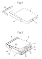
- FIG. 4 to FIG. 9 show an example of assembling steps of the battery pack 1. Firstly, as shown in FIG. 4 , the insulating paper 23 is attached onto the side surface of the battery cell 2 and subsequently one end side of the PTC tab 22 is welded to the cell's negative pole portion. Simultaneously, the other end side of the PTC tab 22 is held while aligning with the third side surface 2c of the battery cell 2. Then, as shown in FIG.
- the battery cell 2 is placed in the frame portion 3, thereby placing the end portion of the second side surface 2b of the battery cell 2 between the flange-like protrusions 35, 36 that are formed on the frame portion 3 and permitting the cell' s positive pole portion 21 to fit the cell' s positive pole portion fitting window 31 of the frame portion 3, as shown in FIG. 6 .
- the end portion of the PTC tab 22 faces the window portion 32 of the frame portion 3.
- the end portion of the shorter side of the L-shaped positive pole tab 45 is welded onto the cell's positive pole portion 21 and is mounted while the longer side thereof being aligned with the outer surface of the first side 3a of the frame portion 3, and the one end 45a of the shorter side of the L-shaped positive pole tab 45 is welded onto the terminal portion 44 at one end of the circuit board unit 4.
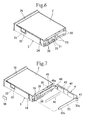
- the longer side of the L-shaped negative pole tab 33 is set to be parallel with the first side 3a of the frame portion 3 and the longer side of the L-shaped positive pole tab 45 mounted on this first side 3a by welding one end 33a of the shorter side of the L-shaped negative pole tab 33.
- the shorter side of the positive pole tab 45 is bent at substantially 180 degrees so that the circuit board unit 4 overlaps on the outer surface of the first side 3a of the frame portion 3 by way of the insulating paper 46, thereby mounting the circuit board unit 4 to the circuit board unit mounting portion 37.
- the other end 33b of the negative pole tab 33 is inserted into the frame portion 3 through the slit 34.
- annealing treatment is already performed on the metal plate constituting the positive pole tab 45, thereby making it easy to be bent at substantially 180 degrees and thus preventing stress being applied onto the circuit board unit 4.
- the negative pole tab 33 and the PTC tab 22 at the window portion 32 so that the negative pole tab 33 and the PTC tab 22 are overlapped each other after mounting the cap portion 5, it is possible to adjust the length of the negative pole tab 33 and the PTC tab 22, and avoid any stress to be applied to the circuit board unit 4 by way of the negative pole tab 33 due to variation in the welding position.
- the spacer 56 is mounted onto the window portion 32 after the negative pole tab 33 and the PTC tab 22 are welded.
- the outer packaging film 6 is wrapped by given at least more than one turn to adhere the end portions 6a so that it integrally combines the battery cell 2, the frame portion 3, the circuit board unit 4 and the cap portion 5, thereby completing the battery pack 1.
- the outer packaging film 6 to be wrapped may be formed previously in a ring shape as shown in FIG. 9 for ease of wrapping or it may be a flat sheet. Also, the outer packaging film 6 may be a single sheet or may be separated into a plurality of sheets. It is to be noted, as shown in FIG. 9 , that an area 71 where the outer packaging film 6 is wrapped may be formed thinner than other areas 72, 73 where the outer packaging film 9 is not wrapped, by the amount equal to the thickness of the outer packaging film 6 to be wrapped, so that the overall outer surface of the battery pack 1 becomes substantially same level after the outer packaging film 6 is wrapped.
Applications Claiming Priority (2)
| Application Number | Priority Date | Filing Date | Title |
|---|---|---|---|
| JP2003357471 | 2003-10-17 | ||
| EP04256384.1A EP1524710B1 (fr) | 2003-10-17 | 2004-10-15 | Structure de pile plate, bloc de piles et procédé de fabrication du bloc de piles |
Related Parent Applications (3)
| Application Number | Title | Priority Date | Filing Date |
|---|---|---|---|
| EP04256384.1A Division-Into EP1524710B1 (fr) | 2003-10-17 | 2004-10-15 | Structure de pile plate, bloc de piles et procédé de fabrication du bloc de piles |
| EP04256384.1A Division EP1524710B1 (fr) | 2003-10-17 | 2004-10-15 | Structure de pile plate, bloc de piles et procédé de fabrication du bloc de piles |
| EP04256384.1 Division | 2004-10-15 |
Publications (2)
| Publication Number | Publication Date |
|---|---|
| EP2256843A1 true EP2256843A1 (fr) | 2010-12-01 |
| EP2256843B1 EP2256843B1 (fr) | 2016-03-30 |
Family
ID=34373621
Family Applications (2)
| Application Number | Title | Priority Date | Filing Date |
|---|---|---|---|
| EP04256384.1A Not-in-force EP1524710B1 (fr) | 2003-10-17 | 2004-10-15 | Structure de pile plate, bloc de piles et procédé de fabrication du bloc de piles |
| EP10173958.9A Not-in-force EP2256843B1 (fr) | 2003-10-17 | 2004-10-15 | Structure de pile plate, bloc de piles et procédé de fabrication du bloc de piles |
Family Applications Before (1)
| Application Number | Title | Priority Date | Filing Date |
|---|---|---|---|
| EP04256384.1A Not-in-force EP1524710B1 (fr) | 2003-10-17 | 2004-10-15 | Structure de pile plate, bloc de piles et procédé de fabrication du bloc de piles |
Country Status (13)
| Country | Link |
|---|---|
| US (1) | US7964303B2 (fr) |
| EP (2) | EP1524710B1 (fr) |
| JP (2) | JP5013666B2 (fr) |
| KR (1) | KR101093912B1 (fr) |
| CN (2) | CN2831446Y (fr) |
| AU (1) | AU2004220726B2 (fr) |
| DK (1) | DK1524710T3 (fr) |
| ES (1) | ES2456665T3 (fr) |
| HK (1) | HK1078378A1 (fr) |
| MX (1) | MXPA04010047A (fr) |
| MY (1) | MY140550A (fr) |
| SG (1) | SG111236A1 (fr) |
| TW (1) | TWI283941B (fr) |
Families Citing this family (59)
| Publication number | Priority date | Publication date | Assignee | Title |
|---|---|---|---|---|
| JP4123517B2 (ja) | 2003-12-26 | 2008-07-23 | ソニー株式会社 | バッテリー装置 |
| JP3899521B2 (ja) | 2004-03-31 | 2007-03-28 | ソニー株式会社 | バッテリー装置 |
| WO2006046343A1 (fr) * | 2004-10-27 | 2006-05-04 | Matsushita Electric Industrial Co., Ltd. | Bloc de batteries |
| TW200640055A (en) * | 2004-12-28 | 2006-11-16 | Sony Corp | Battery, charging apparatus and electronic device |
| KR20060105208A (ko) * | 2005-04-01 | 2006-10-11 | 주식회사 엘지화학 | 매우 얇은 두께의 전지팩 |
| US20100143793A1 (en) * | 2005-05-25 | 2010-06-10 | Hiroshi Yamamoto | Battery Pack |
| JP4561542B2 (ja) | 2005-09-02 | 2010-10-13 | ソニー株式会社 | 二次電池 |
| KR100719731B1 (ko) * | 2005-12-28 | 2007-05-17 | 삼성에스디아이 주식회사 | 얼라인먼트 마크를 갖는 전지 팩 |
| KR100778981B1 (ko) * | 2005-12-29 | 2007-11-22 | 삼성에스디아이 주식회사 | 배터리 팩 |
| JP4293226B2 (ja) | 2006-11-02 | 2009-07-08 | ソニー株式会社 | バッテリ |
| KR100839783B1 (ko) * | 2007-01-03 | 2008-06-19 | 삼성에스디아이 주식회사 | 이차전지 |
| KR100864887B1 (ko) | 2007-05-25 | 2008-10-22 | 삼성에스디아이 주식회사 | 이차 전지 |
| GB2470271B (en) * | 2007-10-16 | 2012-04-11 | Qinetiq Ltd | Modular pellet tray assembly for use in a pyrolytic hydrogen generator |
| JP5291322B2 (ja) | 2007-10-26 | 2013-09-18 | 日立マクセル株式会社 | 電池パック |
| KR100928120B1 (ko) | 2007-11-07 | 2009-11-24 | 삼성에스디아이 주식회사 | 이차 전지 |
| KR100947981B1 (ko) | 2007-11-12 | 2010-03-18 | 삼성에스디아이 주식회사 | 전지 팩 |
| US8691429B2 (en) * | 2008-10-14 | 2014-04-08 | Samsung Sdi Co., Ltd. | Polymer battery pack and method for manufacturing the same |
| KR101023870B1 (ko) | 2009-01-08 | 2011-03-22 | 삼성에스디아이 주식회사 | 파우치형 리튬 이차전지 |
| CN101814623A (zh) * | 2009-02-20 | 2010-08-25 | 日立麦克赛尔株式会社 | 电池组件以及电池组件的制造方法 |
| CN101826639B (zh) * | 2009-03-04 | 2013-10-02 | 比亚迪股份有限公司 | 一种锂离子电池 |
| JP2010257605A (ja) * | 2009-04-21 | 2010-11-11 | Hitachi Maxell Ltd | 電池パック |
| EP2325917B1 (fr) * | 2009-10-21 | 2014-03-12 | Samsung SDI Co., Ltd. | Ensemble de batterie |
| KR101101022B1 (ko) | 2009-11-30 | 2011-12-29 | 삼성에스디아이 주식회사 | 배터리 팩 |
| KR101100971B1 (ko) | 2009-11-30 | 2011-12-29 | 삼성에스디아이 주식회사 | 배터리 팩 |
| KR101113381B1 (ko) | 2009-11-30 | 2012-03-02 | 삼성에스디아이 주식회사 | 배터리 팩 |
| KR101101019B1 (ko) | 2009-12-04 | 2011-12-29 | 삼성에스디아이 주식회사 | 배터리 팩 |
| US8883343B2 (en) * | 2010-01-25 | 2014-11-11 | GM Global Technology Operations LLC | Extended range electric vehicle battery cell packaging for pouch design |
| US20110250474A1 (en) * | 2010-04-13 | 2011-10-13 | Samsung Sdi Co., Ltd. | Secondary battery |
| US9350001B2 (en) | 2010-07-09 | 2016-05-24 | Samsung Sdi Co., Ltd. | Battery pack for a lithium polymer Battery |
| US8940429B2 (en) * | 2010-07-16 | 2015-01-27 | Apple Inc. | Construction of non-rectangular batteries |
| US20120052341A1 (en) * | 2010-09-01 | 2012-03-01 | Duk-Jung Kim | Rechargeable battery |
| KR101234240B1 (ko) | 2011-02-11 | 2013-02-18 | 삼성에스디아이 주식회사 | 코어팩과 보호회로모듈 사이의 격벽을 포함하는 배터리 팩 |
| KR101243911B1 (ko) * | 2011-03-16 | 2013-03-14 | 삼성에스디아이 주식회사 | 배터리 팩 |
| TWM427683U (en) * | 2011-09-28 | 2012-04-21 | Uer Technology Corp | Thin type battery and package structure thereof |
| KR101403384B1 (ko) * | 2011-12-20 | 2014-06-03 | 주식회사 엘지화학 | 신규한 구조의 전지팩 |
| CN103208605A (zh) * | 2012-01-11 | 2013-07-17 | 原瑞电池科技股份有限公司 | 薄型电池 |
| CN103220878A (zh) * | 2012-01-18 | 2013-07-24 | 原瑞电池科技股份有限公司 | 薄型电池与电路板的组合装置 |
| KR101539691B1 (ko) * | 2012-10-19 | 2015-07-27 | 주식회사 엘지화학 | 파우치형 이차 전지의 프레임, 이를 포함하는 배터리 팩 및 배터리 팩의 제조 방법 |
| TWI657330B (zh) | 2012-10-23 | 2019-04-21 | 佳能企業股份有限公司 | 保護結構及電子元件保護結構 |
| US20140120379A1 (en) * | 2012-11-01 | 2014-05-01 | Samsung Sdi Co., Ltd. | Battery pack |
| US9748548B2 (en) | 2013-07-30 | 2017-08-29 | Johnson Controls Technology Company | Pouch frame with integral circuitry for battery module |
| JP2015043274A (ja) * | 2013-08-26 | 2015-03-05 | 三洋電機株式会社 | 電池パック |
| KR101650040B1 (ko) * | 2013-09-30 | 2016-08-22 | 주식회사 엘지화학 | 안정성이 향상된 전지팩 |
| KR20150091790A (ko) * | 2014-02-04 | 2015-08-12 | 삼성에스디아이 주식회사 | 폴리머 배터리 팩 |
| KR101493829B1 (ko) * | 2014-03-27 | 2015-02-16 | 삼성에스디아이 주식회사 | 전지 팩 |
| US9608245B2 (en) | 2014-09-30 | 2017-03-28 | Johnson Controls Technology Company | System for providing structural integrity of a battery module |
| US9980381B2 (en) | 2014-12-16 | 2018-05-22 | Motorola Solutions, Inc. | Method and apparatus for intrinsically safe circuit board arrangement for portable electronic devices |
| US10222879B2 (en) | 2015-03-31 | 2019-03-05 | Microsoft Technology Licensing, Llc | Interlocking integrated battery structure for an electronic stylus |
| KR101969387B1 (ko) * | 2015-06-15 | 2019-04-16 | 주식회사 엘지화학 | 외부 입출력 양극단자가 돌출되어 있는 각형 전지팩 |
| US10062886B2 (en) * | 2015-09-04 | 2018-08-28 | Apple Inc. | Integrated component cap and spacer for battery pack |
| US9929393B2 (en) | 2015-09-30 | 2018-03-27 | Apple Inc. | Wound battery cells with notches accommodating electrode connections |
| KR101972135B1 (ko) * | 2015-10-29 | 2019-04-24 | 주식회사 엘지화학 | 하부 케이스의 두께가 얇은 전지팩 및 이를 포함하는 노트북 컴퓨터 |
| US10868290B2 (en) | 2016-02-26 | 2020-12-15 | Apple Inc. | Lithium-metal batteries having improved dimensional stability and methods of manufacture |
| US11532497B2 (en) | 2016-06-07 | 2022-12-20 | Applied Materials, Inc. | High power electrostatic chuck design with radio frequency coupling |
| KR20180072221A (ko) | 2016-12-21 | 2018-06-29 | 삼성전자주식회사 | 이차 전지 및 이를 포함하는 전지 모듈 |
| DE102017205148A1 (de) * | 2017-03-27 | 2018-09-27 | Volkswagen Aktiengesellschaft | Aufnahmevorrichtung für ein Batteriesystem |
| CN108054423A (zh) * | 2018-01-12 | 2018-05-18 | 漳州万宝能源科技有限公司 | 一种聚合物锂电池 |
| CN109305442B (zh) * | 2018-09-12 | 2020-09-11 | 芜湖乐佳自动化机械有限公司 | 一种纽扣电池用包装纸盒 |
| DE102019217234A1 (de) * | 2019-11-07 | 2021-05-12 | Eberspächer Catem Gmbh & Co. Kg | PTC-Heizeinrichtung und elektrische Heizvorrichtung mit einer solchen PTC- Heizeinrichtung und Verfahren zur Herstellung einer elektrischen Heizvorrichtung |
Citations (5)
| Publication number | Priority date | Publication date | Assignee | Title |
|---|---|---|---|---|
| JP2002110121A (ja) | 2000-09-26 | 2002-04-12 | Gs-Melcotec Co Ltd | 電池パック |
| US20020142195A1 (en) * | 2001-03-30 | 2002-10-03 | Yukio Ehara | Battery pack |
| US20030165736A1 (en) * | 2002-02-06 | 2003-09-04 | Masaru Hiratsuka | Battery pack and method of producing the same |
| US20030173709A1 (en) * | 2000-10-20 | 2003-09-18 | Yoshinori Iwaizono | Method and device for forming outer packaging body of product |
| US20030180582A1 (en) * | 2001-06-28 | 2003-09-25 | Kenjin Masumoto | Cell and cell pack |
Family Cites Families (12)
| Publication number | Priority date | Publication date | Assignee | Title |
|---|---|---|---|---|
| US5399445A (en) * | 1994-04-18 | 1995-03-21 | Aer Energy Resources | Battery case leakage detector |
| JP3767151B2 (ja) * | 1997-02-26 | 2006-04-19 | ソニー株式会社 | 薄型電池 |
| JP4056147B2 (ja) * | 1997-09-30 | 2008-03-05 | 松下電器産業株式会社 | 電池 |
| JP3454748B2 (ja) * | 1999-02-26 | 2003-10-06 | 三洋電機株式会社 | パック電池 |
| KR100484420B1 (ko) * | 1999-03-30 | 2005-04-22 | 마츠시타 덴끼 산교 가부시키가이샤 | 전지보호회로를 구비한 2차 전지 |
| EP1213783A1 (fr) * | 2000-12-08 | 2002-06-12 | Renata AG | Batterie à électrodes bobinées avec dissipateur de chaleur |
| JP2002313295A (ja) * | 2001-04-11 | 2002-10-25 | Gs-Melcotec Co Ltd | 二次電池パック |
| JP2003017020A (ja) * | 2001-06-29 | 2003-01-17 | Sanyo Electric Co Ltd | パック電池 |
| JP3643792B2 (ja) * | 2001-06-29 | 2005-04-27 | 三洋電機株式会社 | パック電池とその製造方法 |
| CN1173428C (zh) * | 2001-07-13 | 2004-10-27 | 比亚迪股份有限公司 | 薄型锂离子电池制造方法 |
| JP4900751B2 (ja) * | 2001-08-22 | 2012-03-21 | 日立マクセルエナジー株式会社 | 薄型電池のパック構造 |
| KR100502337B1 (ko) * | 2002-12-26 | 2005-07-20 | 삼성에스디아이 주식회사 | 리튬 이차 전지 |
-
2004
- 2004-09-29 JP JP2004284263A patent/JP5013666B2/ja not_active Expired - Fee Related
- 2004-10-13 MX MXPA04010047A patent/MXPA04010047A/es active IP Right Grant
- 2004-10-13 SG SG200406152A patent/SG111236A1/en unknown
- 2004-10-14 AU AU2004220726A patent/AU2004220726B2/en not_active Ceased
- 2004-10-15 KR KR1020040082399A patent/KR101093912B1/ko not_active IP Right Cessation
- 2004-10-15 US US10/966,810 patent/US7964303B2/en not_active Expired - Fee Related
- 2004-10-15 MY MYPI20044274A patent/MY140550A/en unknown
- 2004-10-15 TW TW093131442A patent/TWI283941B/zh not_active IP Right Cessation
- 2004-10-15 ES ES04256384.1T patent/ES2456665T3/es active Active
- 2004-10-15 CN CNU2004201182259U patent/CN2831446Y/zh not_active Expired - Lifetime
- 2004-10-15 EP EP04256384.1A patent/EP1524710B1/fr not_active Not-in-force
- 2004-10-15 DK DK04256384.1T patent/DK1524710T3/da active
- 2004-10-15 EP EP10173958.9A patent/EP2256843B1/fr not_active Not-in-force
- 2004-10-15 CN CNB2004100841075A patent/CN100431198C/zh not_active Expired - Fee Related
-
2005
- 2005-11-14 HK HK05110179.7A patent/HK1078378A1/xx not_active IP Right Cessation
-
2011
- 2011-02-28 JP JP2011042788A patent/JP5234126B2/ja not_active Expired - Fee Related
Patent Citations (5)
| Publication number | Priority date | Publication date | Assignee | Title |
|---|---|---|---|---|
| JP2002110121A (ja) | 2000-09-26 | 2002-04-12 | Gs-Melcotec Co Ltd | 電池パック |
| US20030173709A1 (en) * | 2000-10-20 | 2003-09-18 | Yoshinori Iwaizono | Method and device for forming outer packaging body of product |
| US20020142195A1 (en) * | 2001-03-30 | 2002-10-03 | Yukio Ehara | Battery pack |
| US20030180582A1 (en) * | 2001-06-28 | 2003-09-25 | Kenjin Masumoto | Cell and cell pack |
| US20030165736A1 (en) * | 2002-02-06 | 2003-09-04 | Masaru Hiratsuka | Battery pack and method of producing the same |
Also Published As
| Publication number | Publication date |
|---|---|
| US7964303B2 (en) | 2011-06-21 |
| MXPA04010047A (es) | 2005-06-17 |
| CN2831446Y (zh) | 2006-10-25 |
| JP5013666B2 (ja) | 2012-08-29 |
| EP1524710B1 (fr) | 2014-03-12 |
| AU2004220726B2 (en) | 2010-07-01 |
| EP2256843B1 (fr) | 2016-03-30 |
| CN1670983A (zh) | 2005-09-21 |
| JP2005142153A (ja) | 2005-06-02 |
| TW200520287A (en) | 2005-06-16 |
| JP5234126B2 (ja) | 2013-07-10 |
| EP1524710A3 (fr) | 2007-05-02 |
| AU2004220726A1 (en) | 2005-05-05 |
| MY140550A (en) | 2009-12-31 |
| SG111236A1 (en) | 2005-05-30 |
| CN100431198C (zh) | 2008-11-05 |
| DK1524710T3 (da) | 2014-04-22 |
| KR20050037366A (ko) | 2005-04-21 |
| TWI283941B (en) | 2007-07-11 |
| ES2456665T3 (es) | 2014-04-23 |
| US20050112415A1 (en) | 2005-05-26 |
| HK1078378A1 (en) | 2006-03-10 |
| KR101093912B1 (ko) | 2011-12-13 |
| JP2011108663A (ja) | 2011-06-02 |
| EP1524710A2 (fr) | 2005-04-20 |
Similar Documents
| Publication | Publication Date | Title |
|---|---|---|
| EP2256843B1 (fr) | Structure de pile plate, bloc de piles et procédé de fabrication du bloc de piles | |
| US8313856B2 (en) | Structure of thin battery covered by outer packaging film, battery pack, and method for manufacturing battery pack | |
| US7597994B2 (en) | Battery pack | |
| EP1714334B1 (fr) | Accumulateur a structure de type assemblage | |
| US6451474B1 (en) | Resiliently deformable battery pack | |
| US20020142195A1 (en) | Battery pack | |
| JP3503516B2 (ja) | 薄型電池、電子機器及び薄型電池の製造方法 | |
| EP3975323A1 (fr) | Batterie secondaire, dispositif, et procédé de fabrication de batterie secondaire | |
| US7132196B2 (en) | Battery pack | |
| US7635535B2 (en) | Battery pack comprising a battery and a terminal unit | |
| WO2003096446A1 (fr) | Batterie mince | |
| JP5405196B2 (ja) | パック電池およびパック電池中間体 | |
| US20210249723A1 (en) | Battery cell, battery module, battery pack, device using battery cell as power source, and assembling method of battery cell | |
| JP4488730B2 (ja) | 薄型バッテリーパック | |
| EP1187430B1 (fr) | Structure de paroi de couverture et appareil électronique | |
| KR102221781B1 (ko) | 배터리 팩 | |
| JP4598214B2 (ja) | バッテリーパック | |
| JP3762737B2 (ja) | 電池パック | |
| CN210668435U (zh) | 电池及电子设备 | |
| CN219873750U (zh) | 壳体组件、电池和电子设备 | |
| JP4073619B2 (ja) | 電池パック |
Legal Events
| Date | Code | Title | Description |
|---|---|---|---|
| PUAI | Public reference made under article 153(3) epc to a published international application that has entered the european phase |
Free format text: ORIGINAL CODE: 0009012 |
|
| 17P | Request for examination filed |
Effective date: 20100916 |
|
| AC | Divisional application: reference to earlier application |
Ref document number: 1524710 Country of ref document: EP Kind code of ref document: P |
|
| AK | Designated contracting states |
Kind code of ref document: A1 Designated state(s): AT BE BG CH CY CZ DE DK EE ES FI FR GB GR HU IE IT LI LU MC NL PL PT RO SE SI SK TR |
|
| 17Q | First examination report despatched |
Effective date: 20130827 |
|
| RIC1 | Information provided on ipc code assigned before grant |
Ipc: H01M 10/04 20060101ALI20150731BHEP Ipc: H01M 10/44 20060101ALI20150731BHEP Ipc: H01M 2/02 20060101ALI20150731BHEP Ipc: H01M 2/10 20060101AFI20150731BHEP Ipc: H01M 2/04 20060101ALI20150731BHEP |
|
| GRAP | Despatch of communication of intention to grant a patent |
Free format text: ORIGINAL CODE: EPIDOSNIGR1 |
|
| INTG | Intention to grant announced |
Effective date: 20151007 |
|
| GRAS | Grant fee paid |
Free format text: ORIGINAL CODE: EPIDOSNIGR3 |
|
| GRAA | (expected) grant |
Free format text: ORIGINAL CODE: 0009210 |
|
| AC | Divisional application: reference to earlier application |
Ref document number: 1524710 Country of ref document: EP Kind code of ref document: P |
|
| AK | Designated contracting states |
Kind code of ref document: B1 Designated state(s): AT BE BG CH CY CZ DE DK EE ES FI FR GB GR HU IE IT LI LU MC NL PL PT RO SE SI SK TR |
|
| REG | Reference to a national code |
Ref country code: GB Ref legal event code: FG4D |
|
| REG | Reference to a national code |
Ref country code: CH Ref legal event code: EP |
|
| REG | Reference to a national code |
Ref country code: AT Ref legal event code: REF Ref document number: 786241 Country of ref document: AT Kind code of ref document: T Effective date: 20160415 |
|
| REG | Reference to a national code |
Ref country code: IE Ref legal event code: FG4D |
|
| REG | Reference to a national code |
Ref country code: DE Ref legal event code: R096 Ref document number: 602004048955 Country of ref document: DE |
|
| PG25 | Lapsed in a contracting state [announced via postgrant information from national office to epo] |
Ref country code: FI Free format text: LAPSE BECAUSE OF FAILURE TO SUBMIT A TRANSLATION OF THE DESCRIPTION OR TO PAY THE FEE WITHIN THE PRESCRIBED TIME-LIMIT Effective date: 20160330 Ref country code: GR Free format text: LAPSE BECAUSE OF FAILURE TO SUBMIT A TRANSLATION OF THE DESCRIPTION OR TO PAY THE FEE WITHIN THE PRESCRIBED TIME-LIMIT Effective date: 20160701 |
|
| REG | Reference to a national code |
Ref country code: NL Ref legal event code: MP Effective date: 20160330 |
|
| REG | Reference to a national code |
Ref country code: AT Ref legal event code: MK05 Ref document number: 786241 Country of ref document: AT Kind code of ref document: T Effective date: 20160330 |
|
| PG25 | Lapsed in a contracting state [announced via postgrant information from national office to epo] |
Ref country code: SE Free format text: LAPSE BECAUSE OF FAILURE TO SUBMIT A TRANSLATION OF THE DESCRIPTION OR TO PAY THE FEE WITHIN THE PRESCRIBED TIME-LIMIT Effective date: 20160330 |
|
| PG25 | Lapsed in a contracting state [announced via postgrant information from national office to epo] |
Ref country code: NL Free format text: LAPSE BECAUSE OF FAILURE TO SUBMIT A TRANSLATION OF THE DESCRIPTION OR TO PAY THE FEE WITHIN THE PRESCRIBED TIME-LIMIT Effective date: 20160330 |
|
| PG25 | Lapsed in a contracting state [announced via postgrant information from national office to epo] |
Ref country code: EE Free format text: LAPSE BECAUSE OF FAILURE TO SUBMIT A TRANSLATION OF THE DESCRIPTION OR TO PAY THE FEE WITHIN THE PRESCRIBED TIME-LIMIT Effective date: 20160330 Ref country code: PL Free format text: LAPSE BECAUSE OF FAILURE TO SUBMIT A TRANSLATION OF THE DESCRIPTION OR TO PAY THE FEE WITHIN THE PRESCRIBED TIME-LIMIT Effective date: 20160330 |
|
| PG25 | Lapsed in a contracting state [announced via postgrant information from national office to epo] |
Ref country code: AT Free format text: LAPSE BECAUSE OF FAILURE TO SUBMIT A TRANSLATION OF THE DESCRIPTION OR TO PAY THE FEE WITHIN THE PRESCRIBED TIME-LIMIT Effective date: 20160330 Ref country code: PT Free format text: LAPSE BECAUSE OF FAILURE TO SUBMIT A TRANSLATION OF THE DESCRIPTION OR TO PAY THE FEE WITHIN THE PRESCRIBED TIME-LIMIT Effective date: 20160801 Ref country code: ES Free format text: LAPSE BECAUSE OF FAILURE TO SUBMIT A TRANSLATION OF THE DESCRIPTION OR TO PAY THE FEE WITHIN THE PRESCRIBED TIME-LIMIT Effective date: 20160330 Ref country code: SK Free format text: LAPSE BECAUSE OF FAILURE TO SUBMIT A TRANSLATION OF THE DESCRIPTION OR TO PAY THE FEE WITHIN THE PRESCRIBED TIME-LIMIT Effective date: 20160330 Ref country code: CZ Free format text: LAPSE BECAUSE OF FAILURE TO SUBMIT A TRANSLATION OF THE DESCRIPTION OR TO PAY THE FEE WITHIN THE PRESCRIBED TIME-LIMIT Effective date: 20160330 Ref country code: RO Free format text: LAPSE BECAUSE OF FAILURE TO SUBMIT A TRANSLATION OF THE DESCRIPTION OR TO PAY THE FEE WITHIN THE PRESCRIBED TIME-LIMIT Effective date: 20160330 |
|
| PG25 | Lapsed in a contracting state [announced via postgrant information from national office to epo] |
Ref country code: IT Free format text: LAPSE BECAUSE OF FAILURE TO SUBMIT A TRANSLATION OF THE DESCRIPTION OR TO PAY THE FEE WITHIN THE PRESCRIBED TIME-LIMIT Effective date: 20160330 Ref country code: BE Free format text: LAPSE BECAUSE OF FAILURE TO SUBMIT A TRANSLATION OF THE DESCRIPTION OR TO PAY THE FEE WITHIN THE PRESCRIBED TIME-LIMIT Effective date: 20160330 |
|
| REG | Reference to a national code |
Ref country code: DE Ref legal event code: R097 Ref document number: 602004048955 Country of ref document: DE |
|
| PG25 | Lapsed in a contracting state [announced via postgrant information from national office to epo] |
Ref country code: DK Free format text: LAPSE BECAUSE OF FAILURE TO SUBMIT A TRANSLATION OF THE DESCRIPTION OR TO PAY THE FEE WITHIN THE PRESCRIBED TIME-LIMIT Effective date: 20160330 |
|
| PLBE | No opposition filed within time limit |
Free format text: ORIGINAL CODE: 0009261 |
|
| STAA | Information on the status of an ep patent application or granted ep patent |
Free format text: STATUS: NO OPPOSITION FILED WITHIN TIME LIMIT |
|
| 26N | No opposition filed |
Effective date: 20170103 |
|
| PG25 | Lapsed in a contracting state [announced via postgrant information from national office to epo] |
Ref country code: SI Free format text: LAPSE BECAUSE OF FAILURE TO SUBMIT A TRANSLATION OF THE DESCRIPTION OR TO PAY THE FEE WITHIN THE PRESCRIBED TIME-LIMIT Effective date: 20160330 |
|
| REG | Reference to a national code |
Ref country code: CH Ref legal event code: PL |
|
| REG | Reference to a national code |
Ref country code: IE Ref legal event code: MM4A |
|
| REG | Reference to a national code |
Ref country code: FR Ref legal event code: ST Effective date: 20170630 |
|
| PG25 | Lapsed in a contracting state [announced via postgrant information from national office to epo] |
Ref country code: CH Free format text: LAPSE BECAUSE OF NON-PAYMENT OF DUE FEES Effective date: 20161031 Ref country code: LI Free format text: LAPSE BECAUSE OF NON-PAYMENT OF DUE FEES Effective date: 20161031 Ref country code: FR Free format text: LAPSE BECAUSE OF NON-PAYMENT OF DUE FEES Effective date: 20161102 |
|
| PG25 | Lapsed in a contracting state [announced via postgrant information from national office to epo] |
Ref country code: LU Free format text: LAPSE BECAUSE OF NON-PAYMENT OF DUE FEES Effective date: 20161015 |
|
| PG25 | Lapsed in a contracting state [announced via postgrant information from national office to epo] |
Ref country code: IE Free format text: LAPSE BECAUSE OF NON-PAYMENT OF DUE FEES Effective date: 20161015 |
|
| PGFP | Annual fee paid to national office [announced via postgrant information from national office to epo] |
Ref country code: DE Payment date: 20171019 Year of fee payment: 14 |
|
| PGFP | Annual fee paid to national office [announced via postgrant information from national office to epo] |
Ref country code: GB Payment date: 20171019 Year of fee payment: 14 |
|
| PG25 | Lapsed in a contracting state [announced via postgrant information from national office to epo] |
Ref country code: CY Free format text: LAPSE BECAUSE OF FAILURE TO SUBMIT A TRANSLATION OF THE DESCRIPTION OR TO PAY THE FEE WITHIN THE PRESCRIBED TIME-LIMIT Effective date: 20160330 Ref country code: HU Free format text: LAPSE BECAUSE OF FAILURE TO SUBMIT A TRANSLATION OF THE DESCRIPTION OR TO PAY THE FEE WITHIN THE PRESCRIBED TIME-LIMIT; INVALID AB INITIO Effective date: 20041015 |
|
| PG25 | Lapsed in a contracting state [announced via postgrant information from national office to epo] |
Ref country code: MC Free format text: LAPSE BECAUSE OF FAILURE TO SUBMIT A TRANSLATION OF THE DESCRIPTION OR TO PAY THE FEE WITHIN THE PRESCRIBED TIME-LIMIT Effective date: 20160330 Ref country code: TR Free format text: LAPSE BECAUSE OF FAILURE TO SUBMIT A TRANSLATION OF THE DESCRIPTION OR TO PAY THE FEE WITHIN THE PRESCRIBED TIME-LIMIT Effective date: 20160330 |
|
| PG25 | Lapsed in a contracting state [announced via postgrant information from national office to epo] |
Ref country code: BG Free format text: LAPSE BECAUSE OF FAILURE TO SUBMIT A TRANSLATION OF THE DESCRIPTION OR TO PAY THE FEE WITHIN THE PRESCRIBED TIME-LIMIT Effective date: 20160330 |
|
| REG | Reference to a national code |
Ref country code: DE Ref legal event code: R119 Ref document number: 602004048955 Country of ref document: DE |
|
| GBPC | Gb: european patent ceased through non-payment of renewal fee |
Effective date: 20181015 |
|
| PG25 | Lapsed in a contracting state [announced via postgrant information from national office to epo] |
Ref country code: DE Free format text: LAPSE BECAUSE OF NON-PAYMENT OF DUE FEES Effective date: 20190501 |
|
| PG25 | Lapsed in a contracting state [announced via postgrant information from national office to epo] |
Ref country code: GB Free format text: LAPSE BECAUSE OF NON-PAYMENT OF DUE FEES Effective date: 20181015 |