EP2256402A1 - Light-emitting element lamp and lighting fixture - Google Patents
Light-emitting element lamp and lighting fixture Download PDFInfo
- Publication number
- EP2256402A1 EP2256402A1 EP09769995A EP09769995A EP2256402A1 EP 2256402 A1 EP2256402 A1 EP 2256402A1 EP 09769995 A EP09769995 A EP 09769995A EP 09769995 A EP09769995 A EP 09769995A EP 2256402 A1 EP2256402 A1 EP 2256402A1
- Authority
- EP
- European Patent Office
- Prior art keywords
- light
- thermally conductive
- substrate
- emitting element
- cover
- Prior art date
- Legal status (The legal status is an assumption and is not a legal conclusion. Google has not performed a legal analysis and makes no representation as to the accuracy of the status listed.)
- Withdrawn
Links
Images

Classifications
-
- F—MECHANICAL ENGINEERING; LIGHTING; HEATING; WEAPONS; BLASTING
- F21—LIGHTING
- F21V—FUNCTIONAL FEATURES OR DETAILS OF LIGHTING DEVICES OR SYSTEMS THEREOF; STRUCTURAL COMBINATIONS OF LIGHTING DEVICES WITH OTHER ARTICLES, NOT OTHERWISE PROVIDED FOR
- F21V7/00—Reflectors for light sources
- F21V7/0083—Array of reflectors for a cluster of light sources, e.g. arrangement of multiple light sources in one plane
-
- F—MECHANICAL ENGINEERING; LIGHTING; HEATING; WEAPONS; BLASTING
- F21—LIGHTING
- F21K—NON-ELECTRIC LIGHT SOURCES USING LUMINESCENCE; LIGHT SOURCES USING ELECTROCHEMILUMINESCENCE; LIGHT SOURCES USING CHARGES OF COMBUSTIBLE MATERIAL; LIGHT SOURCES USING SEMICONDUCTOR DEVICES AS LIGHT-GENERATING ELEMENTS; LIGHT SOURCES NOT OTHERWISE PROVIDED FOR
- F21K9/00—Light sources using semiconductor devices as light-generating elements, e.g. using light-emitting diodes [LED] or lasers
- F21K9/20—Light sources comprising attachment means
- F21K9/23—Retrofit light sources for lighting devices with a single fitting for each light source, e.g. for substitution of incandescent lamps with bayonet or threaded fittings
-
- F—MECHANICAL ENGINEERING; LIGHTING; HEATING; WEAPONS; BLASTING
- F21—LIGHTING
- F21K—NON-ELECTRIC LIGHT SOURCES USING LUMINESCENCE; LIGHT SOURCES USING ELECTROCHEMILUMINESCENCE; LIGHT SOURCES USING CHARGES OF COMBUSTIBLE MATERIAL; LIGHT SOURCES USING SEMICONDUCTOR DEVICES AS LIGHT-GENERATING ELEMENTS; LIGHT SOURCES NOT OTHERWISE PROVIDED FOR
- F21K9/00—Light sources using semiconductor devices as light-generating elements, e.g. using light-emitting diodes [LED] or lasers
- F21K9/20—Light sources comprising attachment means
- F21K9/23—Retrofit light sources for lighting devices with a single fitting for each light source, e.g. for substitution of incandescent lamps with bayonet or threaded fittings
- F21K9/238—Arrangement or mounting of circuit elements integrated in the light source
-
- F—MECHANICAL ENGINEERING; LIGHTING; HEATING; WEAPONS; BLASTING
- F21—LIGHTING
- F21K—NON-ELECTRIC LIGHT SOURCES USING LUMINESCENCE; LIGHT SOURCES USING ELECTROCHEMILUMINESCENCE; LIGHT SOURCES USING CHARGES OF COMBUSTIBLE MATERIAL; LIGHT SOURCES USING SEMICONDUCTOR DEVICES AS LIGHT-GENERATING ELEMENTS; LIGHT SOURCES NOT OTHERWISE PROVIDED FOR
- F21K9/00—Light sources using semiconductor devices as light-generating elements, e.g. using light-emitting diodes [LED] or lasers
- F21K9/60—Optical arrangements integrated in the light source, e.g. for improving the colour rendering index or the light extraction
- F21K9/68—Details of reflectors forming part of the light source
-
- F—MECHANICAL ENGINEERING; LIGHTING; HEATING; WEAPONS; BLASTING
- F21—LIGHTING
- F21V—FUNCTIONAL FEATURES OR DETAILS OF LIGHTING DEVICES OR SYSTEMS THEREOF; STRUCTURAL COMBINATIONS OF LIGHTING DEVICES WITH OTHER ARTICLES, NOT OTHERWISE PROVIDED FOR
- F21V23/00—Arrangement of electric circuit elements in or on lighting devices
- F21V23/003—Arrangement of electric circuit elements in or on lighting devices the elements being electronics drivers or controllers for operating the light source, e.g. for a LED array
- F21V23/004—Arrangement of electric circuit elements in or on lighting devices the elements being electronics drivers or controllers for operating the light source, e.g. for a LED array arranged on a substrate, e.g. a printed circuit board
- F21V23/006—Arrangement of electric circuit elements in or on lighting devices the elements being electronics drivers or controllers for operating the light source, e.g. for a LED array arranged on a substrate, e.g. a printed circuit board the substrate being distinct from the light source holder
-
- F—MECHANICAL ENGINEERING; LIGHTING; HEATING; WEAPONS; BLASTING
- F21—LIGHTING
- F21V—FUNCTIONAL FEATURES OR DETAILS OF LIGHTING DEVICES OR SYSTEMS THEREOF; STRUCTURAL COMBINATIONS OF LIGHTING DEVICES WITH OTHER ARTICLES, NOT OTHERWISE PROVIDED FOR
- F21V29/00—Protecting lighting devices from thermal damage; Cooling or heating arrangements specially adapted for lighting devices or systems
- F21V29/85—Protecting lighting devices from thermal damage; Cooling or heating arrangements specially adapted for lighting devices or systems characterised by the material
- F21V29/87—Organic material, e.g. filled polymer composites; Thermo-conductive additives or coatings therefor
-
- F—MECHANICAL ENGINEERING; LIGHTING; HEATING; WEAPONS; BLASTING
- F21—LIGHTING
- F21V—FUNCTIONAL FEATURES OR DETAILS OF LIGHTING DEVICES OR SYSTEMS THEREOF; STRUCTURAL COMBINATIONS OF LIGHTING DEVICES WITH OTHER ARTICLES, NOT OTHERWISE PROVIDED FOR
- F21V31/00—Gas-tight or water-tight arrangements
- F21V31/005—Sealing arrangements therefor
-
- H—ELECTRICITY
- H05—ELECTRIC TECHNIQUES NOT OTHERWISE PROVIDED FOR
- H05B—ELECTRIC HEATING; ELECTRIC LIGHT SOURCES NOT OTHERWISE PROVIDED FOR; CIRCUIT ARRANGEMENTS FOR ELECTRIC LIGHT SOURCES, IN GENERAL
- H05B45/00—Circuit arrangements for operating light-emitting diodes [LED]
- H05B45/30—Driver circuits
-
- F—MECHANICAL ENGINEERING; LIGHTING; HEATING; WEAPONS; BLASTING
- F21—LIGHTING
- F21V—FUNCTIONAL FEATURES OR DETAILS OF LIGHTING DEVICES OR SYSTEMS THEREOF; STRUCTURAL COMBINATIONS OF LIGHTING DEVICES WITH OTHER ARTICLES, NOT OTHERWISE PROVIDED FOR
- F21V17/00—Fastening of component parts of lighting devices, e.g. shades, globes, refractors, reflectors, filters, screens, grids or protective cages
- F21V17/10—Fastening of component parts of lighting devices, e.g. shades, globes, refractors, reflectors, filters, screens, grids or protective cages characterised by specific fastening means or way of fastening
- F21V17/12—Fastening of component parts of lighting devices, e.g. shades, globes, refractors, reflectors, filters, screens, grids or protective cages characterised by specific fastening means or way of fastening by screwing
-
- F—MECHANICAL ENGINEERING; LIGHTING; HEATING; WEAPONS; BLASTING
- F21—LIGHTING
- F21V—FUNCTIONAL FEATURES OR DETAILS OF LIGHTING DEVICES OR SYSTEMS THEREOF; STRUCTURAL COMBINATIONS OF LIGHTING DEVICES WITH OTHER ARTICLES, NOT OTHERWISE PROVIDED FOR
- F21V21/00—Supporting, suspending, or attaching arrangements for lighting devices; Hand grips
- F21V21/14—Adjustable mountings
- F21V21/30—Pivoted housings or frames
-
- F—MECHANICAL ENGINEERING; LIGHTING; HEATING; WEAPONS; BLASTING
- F21—LIGHTING
- F21V—FUNCTIONAL FEATURES OR DETAILS OF LIGHTING DEVICES OR SYSTEMS THEREOF; STRUCTURAL COMBINATIONS OF LIGHTING DEVICES WITH OTHER ARTICLES, NOT OTHERWISE PROVIDED FOR
- F21V23/00—Arrangement of electric circuit elements in or on lighting devices
- F21V23/001—Arrangement of electric circuit elements in or on lighting devices the elements being electrical wires or cables
-
- F—MECHANICAL ENGINEERING; LIGHTING; HEATING; WEAPONS; BLASTING
- F21—LIGHTING
- F21V—FUNCTIONAL FEATURES OR DETAILS OF LIGHTING DEVICES OR SYSTEMS THEREOF; STRUCTURAL COMBINATIONS OF LIGHTING DEVICES WITH OTHER ARTICLES, NOT OTHERWISE PROVIDED FOR
- F21V31/00—Gas-tight or water-tight arrangements
- F21V31/04—Provision of filling media
-
- F—MECHANICAL ENGINEERING; LIGHTING; HEATING; WEAPONS; BLASTING
- F21—LIGHTING
- F21Y—INDEXING SCHEME ASSOCIATED WITH SUBCLASSES F21K, F21L, F21S and F21V, RELATING TO THE FORM OR THE KIND OF THE LIGHT SOURCES OR OF THE COLOUR OF THE LIGHT EMITTED
- F21Y2115/00—Light-generating elements of semiconductor light sources
- F21Y2115/10—Light-emitting diodes [LED]
-
- H—ELECTRICITY
- H05—ELECTRIC TECHNIQUES NOT OTHERWISE PROVIDED FOR
- H05B—ELECTRIC HEATING; ELECTRIC LIGHT SOURCES NOT OTHERWISE PROVIDED FOR; CIRCUIT ARRANGEMENTS FOR ELECTRIC LIGHT SOURCES, IN GENERAL
- H05B45/00—Circuit arrangements for operating light-emitting diodes [LED]
- H05B45/30—Driver circuits
- H05B45/357—Driver circuits specially adapted for retrofit LED light sources
- H05B45/3574—Emulating the electrical or functional characteristics of incandescent lamps
-
- H—ELECTRICITY
- H10—SEMICONDUCTOR DEVICES; ELECTRIC SOLID-STATE DEVICES NOT OTHERWISE PROVIDED FOR
- H10H—INORGANIC LIGHT-EMITTING SEMICONDUCTOR DEVICES HAVING POTENTIAL BARRIERS
- H10H20/00—Individual inorganic light-emitting semiconductor devices having potential barriers, e.g. light-emitting diodes [LED]
- H10H20/80—Constructional details
- H10H20/85—Packages
- H10H20/855—Optical field-shaping means, e.g. lenses
- H10H20/856—Reflecting means
-
- H—ELECTRICITY
- H10—SEMICONDUCTOR DEVICES; ELECTRIC SOLID-STATE DEVICES NOT OTHERWISE PROVIDED FOR
- H10W—GENERIC PACKAGES, INTERCONNECTIONS, CONNECTORS OR OTHER CONSTRUCTIONAL DETAILS OF DEVICES COVERED BY CLASS H10
- H10W90/00—Package configurations
-
- Y—GENERAL TAGGING OF NEW TECHNOLOGICAL DEVELOPMENTS; GENERAL TAGGING OF CROSS-SECTIONAL TECHNOLOGIES SPANNING OVER SEVERAL SECTIONS OF THE IPC; TECHNICAL SUBJECTS COVERED BY FORMER USPC CROSS-REFERENCE ART COLLECTIONS [XRACs] AND DIGESTS
- Y02—TECHNOLOGIES OR APPLICATIONS FOR MITIGATION OR ADAPTATION AGAINST CLIMATE CHANGE
- Y02B—CLIMATE CHANGE MITIGATION TECHNOLOGIES RELATED TO BUILDINGS, e.g. HOUSING, HOUSE APPLIANCES OR RELATED END-USER APPLICATIONS
- Y02B20/00—Energy efficient lighting technologies, e.g. halogen lamps or gas discharge lamps
- Y02B20/30—Semiconductor lamps, e.g. solid state lamps [SSL] light emitting diodes [LED] or organic LED [OLED]
Definitions
- the present invention relates to a light-emitting element lamp to which light-emitting elements such as LEDs are applied as a light source, and lighting equipment using the light-emitting element lamp.
- the light-emitting element such as an LED
- an increase in temperature thereof results in a lowering in optical output and adversely influences the service life. Therefore, in a lamp in which a solid-state light-emitting element such as an LED and EL element are used as its light source, it is necessary to prevent the temperature of the light-emitting element from rising in order to improve various characteristics such as service life and efficiency.
- a type of LED lamp which is provided with a columnar radiator between a substrate having LEDs disposed thereon and a cap and the substrate is attached to the peripheral edge at the end face of the radiator (For example, refer to Patent Document 1).
- Patent Document 1 the type shown in Patent Document 1 is such that a radiator is specially provided as a countermeasure for heat radiation, and further is shaped so that the substrate is brought into contact with only the peripheral edge of the end face of the radiator. In other words, the radiator is brought into only linear contact with the substrate, wherein it is difficult that a sufficient radiation effect is obtained.
- the present invention was developed in view of the above-described problems and it is an object of the present invention to provide a light-emitting element lamp and lighting equipment in which a temperature rise of the substrate having light-emitting elements mounted thereon can be effectively prevented by using a thermally conductive casing and cover.
- a light-emitting element lamp includes a thermally conductive casing having an irradiation opening, which is formed so as to be widened toward the irradiation opening, having an outer circumferential surface exposed outwardly, and having a substrate mounting part equipped on the inner circumferential surface; a light source part having a substrate having light-emitting elements mounted thereon, in which the substrate is attached so as to be thermally coupled to the substrate mounting part; a thermally conductive cover which is thermally coupled to and connected to the outer circumferential surface of the thermally conductive casing in a surface-contacted state; an insulative cover one end side of which is connected to the thermally conductive cover and the other end side of which has a cap connected thereto; and a lighting circuit which is accommodated in the insulative cover and controls lighting of the light-emitting elements.
- the light-emitting element is a solid-state light-emitting element such as an LED (light-emitting diode) and an organic EL (electro-luminescence). It is preferable that the light-emitting element is mounted by a chip-on-board system and a surface-mounting system. However, the mounting system is not specially restricted in consideration of the features of the present invention. For example, a bullet type LED may be used and mounted on a substrate. Also, there is no special restriction on the number of light-emitting elements to be disposed.
- the thermally conductive casing may be widened toward the irradiation opening continuously or stepwise. In other words, the casing may be widened with a non-continuous shape.
- a light-emitting element lamp according to Claim 2 of the present invention is featured, in addition to the light-emitting element lamp described in Claim 1 of the present invention, in that the thermally conductive casing and the thermally conductive cover are connected to each other with an O-ring intervening therebetween, and power is fed from the lighting circuit to the light source part inside the O-ring.
- a light-emitting element lamp according to Claim 3 of the present invention is featured, in addition to the light-emitting element lamp described in Claim 1 or 2 of the present invention, in that a plurality of light-emitting elements are mounted on the substrate, and a reflector is provided opposite to the substrate, and the reflector includes a plurality of incidence openings corresponding to the plurality of light-emitting elements and a reflection surface which sections the incidence openings and is widened from the incidence openings toward the irradiation direction.
- Lighting equipment according to Claim 4 of the present invention includes an equipment main body having a socket, and a light-emitting element lamp described in Claim 1 or 2 of the present invention, which is mounted in the socket of the equipment main body.
- a temperature rise of the substrate having light-emitting elements mounted thereon can be effectively prevented by using the thermally conductive casing and the thermally conductive cover. Further, since the thermally conductive casing is widened toward the irradiation opening, and the area of the outer circumferential surface which brings about a heat radiation effect is large, the casing is effective in the heat radiation effect. Furthermore, since the thermally conductive casing and the thermally conductive cover are brought into surface contact with each other, the thermal conduction is improved.
- a waterproof feature is maintained with a simple structure, and a power feeding channel to the light source part can be secured, in addition to the effects of the present invention, which are described in Claim 1 of the present invention.
- Claim 4 of the invention in addition to the effects which are brought about by the light-emitting element lamp, it is possible to provide lighting equipment capable of effectively radiating heat by transmitting heat from the cap to the socket.
- Fig. 1 is a sectional view showing the light-emitting element lamp
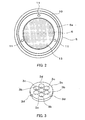
- Fig. 2 is a plan view showing the same light-emitting element lamp with the thermally conductive casing removed
- Fig. 3 is a perspective view showing a reflector of the same light-emitting element lamp
- Fig. 4 is a sectional view showing a reflector of the same light-emitting element lamp.
- the light-emitting element lamp according to the present embodiment can replace the existing reflection type incandescent lamp or a so called beam lamp and has a structure roughly equivalent to the beam lamp in respect to the appearance dimension.
- the beam lamp is suitable as a store spot light, projection illumination of buildings and advertisement sign boards, and illumination of construction sites, etc.
- the light-emitting element lamp 1 has an appearance profile similar to the existing beam lamp, and has a waterproof feature by which the light-emitting element lamp 1 can be used outdoors.
- the light-emitting element lamp 1 is provided with a thermally conductive casing 2, a light source part 3, a reflector 3a, light-emitting elements 4, a thermally conductive cover 5, an insulative cover 6, a cap 7, and a front side lens 8 serving as a transparent cover.
- the thermally conductive casing 2 is composed of, for example, an integrally molded article of aluminum, and the surface thereof is baking-finishedwith white acryl.
- the casing 2 is widened from the base end part 2a toward the irradiation opening 2b, and is formed to be like a bowl having a bottom so that the outer circumferential surface is exposed outwardly.
- the bottom wall of the inner circumferential surface of the thermally conductive casing 2 is formed to be flat, where the substrate mounting part 2c is formed.
- the bottom wall peripheral edge of the outer circumferential surface forms an annular connection part 2d which is connected to the thermally conductive cover 5.
- screw through-holes are formed at three points with a gap of approximately 120 degrees in the circumferential direction in the bottomwall of the thermally conductive casing 2.
- the substrate mounting part 2c is formed to be separate from the thermally conductive casing 2, and the substrate mounting part 2c which is formed separately from the casing 2 may be attached so as to be thermally coupled to the thermally conductive casing 2.
- the material of the thermally conductive casing 2 is not limited to aluminum, wherein a metallic material or a resin material which has favorable thermal conductivity may be used.
- the inner circumferential surface of the thermally conductive casing 2 may be alumite-treated.
- alumite treatment By executing alumite treatment, it becomes possible to increase the heat radiation effect of the thermally conductive casing 2. If alumite treatment is executed, the inner circumferential surface of the thermally conductive casing 2 lowers in the reflection effect. However, since the reflector 3a is separately provided, a lowering in the reflection effect does not hinder the performance. On the other hand, where the inner circumferential surface of the thermally conductive casing 2 is used as the reflection surface, a reflection surface may be formed by mirror-like finishing, etc.
- the light source part 3 is provided on the bottom wall of the thermally conductive casing 2.
- the light source part 3 is provided with a substrate 9 and light-emitting elements 4 mounted on the substrate 9.
- the light-emitting elements 4 are LED chips.
- the LED chips are mounted on the substrate 9 by the chip-on-board system. That is, the LED chips are disposed in the form of a plurality of matrices on the surface of the substrate 9 and are structured so that the surface thereof is coated with a coating material.
- the substrate 9 is composed of a roughly circular flat plate formed of metal, for example, a material which is good in thermal conductivity and excellent in heat radiation properties, such as aluminum.
- the substrate 9 is an insulative material, a ceramic material or a synthetic resin material which is comparatively good in heat radiation properties and excellent in durabilitymay be applied.
- a synthetic resin material for example, the substrate 9 may be formed of, for example, a glass epoxy resin.
- the substrate 9 is attached so as to be brought into surface contact with and be adhered to the substrate mounting part 2c formed on the bottom wall of the thermally conductive casing 2.
- an adhesive glue may be used.
- the surface contact between the substrate 9 and the base mounting part 2c does not have to be an entire surface contact but may be a partial surface contact.
- a reflector 3a formed of white polycarbonate or ASA resin, etc., is disposed on the surface side of the substrate 9.
- the reflector 3a functions to control the distribution of light emitted from the LED chips and to efficiently irradiate the light.
- the reflector 3a is formed to be disk-shaped, and is sectioned by ridge line parts to form a plurality of incidence openings 3b.
- the incidence openings 3b of the reflector 3a are disposed so as to be opposed to respective LED chips of the substrate 9. Therefore, a roughly bowl-shaped reflection surface 3c widened in the irradiation direction, that is, toward the ridge line part from the incidence openings 3b is formed per incidence opening 3b.
- a notched part 3d in which a screw is inserted and locked is formed at three points with a gap of approximately 120 degrees in the circumferential direction on the outer circumferential part of the reflector 3a.
- the thermally conductive cover 5 is made of aluminum die-casting.
- the surface thereof is baking-finished with white acryl, and is made roughly cylindrical so that the cover 5 is tapered continuously with the outer circumferential surface of the thermally conductive casing 2.
- the length and thickness dimensions of the thermally conductive cover 5 may be appropriately determined with the heat radiation effect, etc., taken into consideration.
- the connection part 5a of the thermally conductive cover 5 with the thermally conductive casing 2 is formed to be annular with a predetermined width (Refer to Fig. 2 ).
- the connection part 2d of the thermally conductive casing 2 is formed to be opposed to the corresponding connection part 5a, and they are thermally coupled and connected to each other in a surface-contacted state.
- An annular groove is formed in the connection part 5a.
- An O-ring 10 made of synthetic rubber, etc., is fitted in the groove.
- Three screw holes 11 are formed with a gap of approximately 120 degrees in the circumferential direction inside the O-ring 10.
- An insulative cover 6 molded by PBT resin is provided along the shape of the thermally conductive cover 5 inside the thermally conductive cover 5. Therefore, the insulative cover 6 has one end side thereof connected to the thermally conductive cover 5 and the other end side thereof protruded from the thermally conductive cover 5.
- a cap 7 is fixed at a protrusion part 6a of the insulative cover 6, which protrudes from the thermally conductive cover 5.
- the cap 7 is an E26 cap according to the cap standard, and is a portion which is screwed in a socket of lighting equipment when mounting the light-emitting element lamp 1 in the lighting equipment.
- an air hole 6b is formed in the protrusion part 6a. The air hole 6b is a small hole which functions to reduce the inside pressure when the inside pressure in the insulative cover 6 is increased.
- a lighting circuit 12 is accommodated in the insulative cover 6.
- the lighting circuit 12 controls lighting of the LED chips and is composed of components such as capacitors and transistors as switching elements.
- the lighting circuit 12 is mounted on the circuit substrate 12c, and the circuit substrate 12c is roughly T-shaped and is accommodated in the longitudinal direction in the insulative cover 6. Accordingly, this makes it possible that the circuit substrate 12c is effectively disposed utilizing a narrow space.
- a lead wire 12a is led from the lighting circuit 12, and the lead wire 12a is electrically connected to the substrate 9 of the light source part 3 via a lead wire insertion hole 12b formed in the substrate mounting part 2c.
- the lighting circuit 12 is electrically connected to the cap 7 (illustration thereof omitted) .
- the entirety of the lighting circuit 12 may be accommodated in the insulative cover 6, or may be partially accommodated therein, and the remaining part thereof may be accommodated in the cap 7.
- a filling material 13 is filled up in the insulative cover 6 so as to include and cover the lighting circuit 12.
- the filling material 13 is made of silicone resin and has resiliency, insulation properties and thermal conductivity.
- a liquid filling material 13 is first poured into the insulative cover 6 from upward.
- the filling material 13 is poured to the upper end part level of the insulative cover 6 and is hardened and stabilized in a high temperature atmosphere.
- the front lens 8 is attached so that it encloses the irradiation opening 2b of the thermally conductive casing 2 in an airtight state via a packing (not illustrated) made of silicone resin. Further, there is a light condensing type and a light scattering type for the front lens 8, which may be appropriately selected for use.
- connection part 2d of the thermally conductive casing 2 is disposed so as to be opposed to the connection part 5a of the thermally conductive cover 5.
- the substrate 9 is disposed at the substrate mounting part 2c of the thermally conductive casing 2, and the reflector 3a is caused to overlap thereon.
- the screw 14 is screwed in the screw hole 11 of the thermally conductive cover 5 via the notched part 3d of the reflector 3a and the screw through-hole of the thermally conductive casing 2, wherein the thermally conductive casing 2 is fixed at the thermally conductive cover 5, and the lower end of the reflector 3a presses the surface side of the substrate 9, and both the reflector 3a and the substrate 9 are fixed at the bottom wall of the thermally conductive casing 2.
- the O-ring 10 is resiliently deformed between the connection part 5a and the connection part 2d and makes the gap therebetween airtight. That is, the inside of the O-ring 10 is kept airtight. Therefore, wiring such as electrical connections by means of lead wires 12a between the lighting circuit 12 and the substrate 9 having the LED chips mounted thereon is carried out inside the O-ring 10.
- a connector 15 is provided at the outer circumferential edge of the substrate 9 having the LED chips mounted thereon.
- the connector 15 is composed of a power receiving terminal 15a connected to the wiring pattern of the substrate 9 and a power feeding terminal 15b connected from the wiring pattern of the lighting circuit 12 via the lead wire 12a and forms a socket shape.
- the wiring is carried out inside the O-ring 10, wherein sealing properties of the electrically connected portion can be maintained.
- the connector 15 since the connector 15 is disposed in the horizontal direction and is connected from the horizontal direction, the height dimension thereof is made lower than the reflector 3a, and there is no case where the connector 15 blocks light irradiated from the reflector 3a.
- the lighting circuit 12 operates to feed power to the substrate 9.
- the LED chips emit light.
- Light emitted from the LED chips is controlled by the reflection surface 3c of the reflector 3a mainly per LED chip with respect to the distribution of light, and is irradiated forward, passing through the front lens 8.
- Heat generated from the LED chips in line therewith is transmitted from roughly the entire surface of the rear surface of the substrate 9 to the substrate mounting part 2c, and is further transmitted to the thermally conductive casing 2 having a larger heat radiation area.
- the heat is transmitted from the connection part 2d of the thermally conductive casing 2 to the connection part 5a of the thermally conductive cover 5, and is further transmitted to the entirety of the thermally conductive cover 5.
- the respective members are thermally coupled to each other, wherein it is possible to prevent the temperature rise of the substrate 9 by the above-described thermal transmission channel and radiation.
- heat generated from the light circuit 12 is transmitted to the thermally conductive casing 2 via the filling material 13 and is radiated therefrom, and is further transmitted to the cap 7 and still further transmitted from the cap 7 to the socket, etc., of the lighting equipment and is radiated therefrom.
- the front lens 8 is attached to the irradiation opening 2b of the thermally conductive casing 2 via packing, and the O-ring 10 is provided between the connection part 2d of the thermally conductive casing 2 and the connection part 5a of the thermally conductive cover 5.
- the lighting circuit 12 is enclosed by the filling material 13. Accordingly, since the light-emitting element lamp 1 has electric insulation properties and has weather resistance and rainproof features, the light-emitting element lamp 1 is structured so as to be suitable for outdoor use. Further, such a sealing structure is adopted for this reason.
- the light distribution is controlled by the reflection surface 3c of the reflector 3a per LED chip, wherein desired optical treatment can be carried out without using other light control means.
- the thermally conductive casing 2 is widened toward the irradiation opening 2b, the area of the outer circumferential surface which brings about heat radiation effect, and the casing 2 is effective for the heat radiation effect.
- the thermally conductive casing 2 and the thermally conductive cover 5 are brought into surface contact with each other, the thermal conduction becomes favorable.
- the O-ring 10 is provided between the connection part 2d of the thermally conductive casing 2 and the connection part 5a of the thermally conductive cover 5 to keep sealing properties, it is possible to secure a power feeding channel to the light source part 3 with the waterproof features maintained by a simple structure.
- the components can be commonly utilized, and it is possible to provide an inexpensive light-emitting element lamp 1.
- the lighting equipment 20 is a spot light for outdoor use.
- the lighting equipment 20 is provided with an equipment main body 21 and a base 22 on which the equipment main body 21 is mounted.
- a socket 23 is provided in the equipment main body 21.
- the cap 7 of the light-emitting element lamp 1 is screwed in and mounted in the socket 23.
- the lighting equipment 20 is fixed with the base 22 thereof fixed on the ground, etc., and the direction of the equipment main body 21 is variable with respect to the base 22, and the irradiation direction of light can be optionally changed.
- temperature rise of the substrate 9 of the light-emitting element lamp 1 can be effectively prevented by utilizing the thermally conductive casing 2 and the thermally conductive cover 5, and heat generated from the lighting circuit 12 is mainly transmitted to the cap 7, transmitted from the cap 7 to the socket 23, etc., of the lighting equipment 20 and is radiated therefrom, wherein it is possible to provide lighting equipment 20 capable of further effectively preventing a temperature rise of the substrate 9.
- the present invention is applicable to a light-emitting element lamp, in which light-emitting elements such as LEDs are used as a light source, and lighting equipment in which the light-emitting element lamp is used.
Landscapes
- Engineering & Computer Science (AREA)
- General Engineering & Computer Science (AREA)
- Microelectronics & Electronic Packaging (AREA)
- Physics & Mathematics (AREA)
- Optics & Photonics (AREA)
- Arrangement Of Elements, Cooling, Sealing, Or The Like Of Lighting Devices (AREA)
- Non-Portable Lighting Devices Or Systems Thereof (AREA)
- Led Device Packages (AREA)
- Fastening Of Light Sources Or Lamp Holders (AREA)
Abstract
Description
- The present invention relates to a light-emitting element lamp to which light-emitting elements such as LEDs are applied as a light source, and lighting equipment using the light-emitting element lamp.
- In regard to the light-emitting element such as an LED, an increase in temperature thereof results in a lowering in optical output and adversely influences the service life. Therefore, in a lamp in which a solid-state light-emitting element such as an LED and EL element are used as its light source, it is necessary to prevent the temperature of the light-emitting element from rising in order to improve various characteristics such as service life and efficiency. Conventionally, in this type of LED lamp, such a type of LED lamp has been known which is provided with a columnar radiator between a substrate having LEDs disposed thereon and a cap and the substrate is attached to the peripheral edge at the end face of the radiator (For example, refer to Patent Document 1).
-
- Patent Citation 1: Japanese Laid-Open Patent Publication No.
2005-286267 - However, the type shown in
Patent Document 1 is such that a radiator is specially provided as a countermeasure for heat radiation, and further is shaped so that the substrate is brought into contact with only the peripheral edge of the end face of the radiator. In other words, the radiator is brought into only linear contact with the substrate, wherein it is difficult that a sufficient radiation effect is obtained. - The present invention was developed in view of the above-described problems and it is an object of the present invention to provide a light-emitting element lamp and lighting equipment in which a temperature rise of the substrate having light-emitting elements mounted thereon can be effectively prevented by using a thermally conductive casing and cover.
- A light-emitting element lamp according to
Claim 1 of the present invention includes a thermally conductive casing having an irradiation opening, which is formed so as to be widened toward the irradiation opening, having an outer circumferential surface exposed outwardly, and having a substrate mounting part equipped on the inner circumferential surface; a light source part having a substrate having light-emitting elements mounted thereon, in which the substrate is attached so as to be thermally coupled to the substrate mounting part; a thermally conductive cover which is thermally coupled to and connected to the outer circumferential surface of the thermally conductive casing in a surface-contacted state; an insulative cover one end side of which is connected to the thermally conductive cover and the other end side of which has a cap connected thereto; and a lighting circuit which is accommodated in the insulative cover and controls lighting of the light-emitting elements. - The light-emitting element is a solid-state light-emitting element such as an LED (light-emitting diode) and an organic EL (electro-luminescence). It is preferable that the light-emitting element is mounted by a chip-on-board system and a surface-mounting system. However, the mounting system is not specially restricted in consideration of the features of the present invention. For example, a bullet type LED may be used and mounted on a substrate. Also, there is no special restriction on the number of light-emitting elements to be disposed. The thermally conductive casing may be widened toward the irradiation opening continuously or stepwise. In other words, the casing may be widened with a non-continuous shape.
- A light-emitting element lamp according to
Claim 2 of the present invention is featured, in addition to the light-emitting element lamp described inClaim 1 of the present invention, in that the thermally conductive casing and the thermally conductive cover are connected to each other with an O-ring intervening therebetween, and power is fed from the lighting circuit to the light source part inside the O-ring. - A light-emitting element lamp according to
Claim 3 of the present invention is featured, in addition to the light-emitting element lamp described inClaim - Lighting equipment according to
Claim 4 of the present invention includes an equipment main body having a socket, and a light-emitting element lamp described inClaim - According to
Claim 1 of the present invention, a temperature rise of the substrate having light-emitting elements mounted thereon can be effectively prevented by using the thermally conductive casing and the thermally conductive cover. Further, since the thermally conductive casing is widened toward the irradiation opening, and the area of the outer circumferential surface which brings about a heat radiation effect is large, the casing is effective in the heat radiation effect. Furthermore, since the thermally conductive casing and the thermally conductive cover are brought into surface contact with each other, the thermal conduction is improved. - According to
Claim 2 of the present invention, a waterproof feature is maintained with a simple structure, and a power feeding channel to the light source part can be secured, in addition to the effects of the present invention, which are described inClaim 1 of the present invention. - According to
Claim 3 of the present invention, in addition to the effects ofClaim - According to
Claim 4 of the invention, in addition to the effects which are brought about by the light-emitting element lamp, it is possible to provide lighting equipment capable of effectively radiating heat by transmitting heat from the cap to the socket. -
-
Fig. 1 is a sectional view showing a light-emitting element lamp according to an embodiment of the present invention; -
Fig. 2 is a plan view showing the same light-emitting element lamp with the thermally conductive casing removed; -
Fig. 3 is a perspective view showing a reflector of the same light-emitting element lamp; -
Fig. 4 i's a sectional view showing a reflector of the same light-emitting element lamp; and -
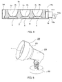
Fig. 5 is a perspective view showing lighting equipment according to the embodiment of the present invention. - Hereinafter, a description is given of a light-emitting element lamp according to the embodiment of the present invention with reference to
Fig. 1 through Fig. 4 .Fig. 1 is a sectional view showing the light-emitting element lamp,Fig. 2 is a plan view showing the same light-emitting element lamp with the thermally conductive casing removed,Fig. 3 is a perspective view showing a reflector of the same light-emitting element lamp, andFig. 4 is a sectional view showing a reflector of the same light-emitting element lamp. The light-emitting element lamp according to the present embodiment can replace the existing reflection type incandescent lamp or a so called beam lamp and has a structure roughly equivalent to the beam lamp in respect to the appearance dimension. The beam lamp is suitable as a store spot light, projection illumination of buildings and advertisement sign boards, and illumination of construction sites, etc. - In
Fig. 1 , the light-emitting element lamp 1 has an appearance profile similar to the existing beam lamp, and has a waterproof feature by which the light-emittingelement lamp 1 can be used outdoors. The light-emittingelement lamp 1 is provided with a thermallyconductive casing 2, alight source part 3, areflector 3a, light-emittingelements 4, a thermallyconductive cover 5, aninsulative cover 6, acap 7, and afront side lens 8 serving as a transparent cover. - The thermally
conductive casing 2 is composed of, for example, an integrally molded article of aluminum, and the surface thereof is baking-finishedwith white acryl. Thecasing 2 is widened from thebase end part 2a toward the irradiation opening 2b, and is formed to be like a bowl having a bottom so that the outer circumferential surface is exposed outwardly. The bottom wall of the inner circumferential surface of the thermallyconductive casing 2 is formed to be flat, where thesubstrate mounting part 2c is formed. On the other hand, the bottom wall peripheral edge of the outer circumferential surface forms anannular connection part 2d which is connected to the thermallyconductive cover 5. In addition, screw through-holes are formed at three points with a gap of approximately 120 degrees in the circumferential direction in the bottomwall of the thermallyconductive casing 2. Further, thesubstrate mounting part 2c is formed to be separate from the thermallyconductive casing 2, and thesubstrate mounting part 2c which is formed separately from thecasing 2 may be attached so as to be thermally coupled to the thermallyconductive casing 2. Still further, the material of the thermallyconductive casing 2 is not limited to aluminum, wherein a metallic material or a resin material which has favorable thermal conductivity may be used. In addition, it is preferable that the inner circumferential surface of the thermallyconductive casing 2 may be alumite-treated. By executing alumite treatment, it becomes possible to increase the heat radiation effect of the thermallyconductive casing 2. If alumite treatment is executed, the inner circumferential surface of the thermallyconductive casing 2 lowers in the reflection effect. However, since thereflector 3a is separately provided, a lowering in the reflection effect does not hinder the performance. On the other hand, where the inner circumferential surface of the thermallyconductive casing 2 is used as the reflection surface, a reflection surface may be formed by mirror-like finishing, etc. - The
light source part 3 is provided on the bottom wall of the thermallyconductive casing 2. Thelight source part 3 is provided with asubstrate 9 and light-emittingelements 4 mounted on thesubstrate 9. The light-emittingelements 4 are LED chips. The LED chips are mounted on thesubstrate 9 by the chip-on-board system. That is, the LED chips are disposed in the form of a plurality of matrices on the surface of thesubstrate 9 and are structured so that the surface thereof is coated with a coating material. Thesubstrate 9 is composed of a roughly circular flat plate formed of metal, for example, a material which is good in thermal conductivity and excellent in heat radiation properties, such as aluminum. Where thesubstrate 9 is an insulative material, a ceramic material or a synthetic resin material which is comparatively good in heat radiation properties and excellent in durabilitymay be applied. Where a synthetic resin material is used, for example, thesubstrate 9 may be formed of, for example, a glass epoxy resin. - And, the
substrate 9 is attached so as to be brought into surface contact with and be adhered to thesubstrate mounting part 2c formed on the bottom wall of the thermallyconductive casing 2. When attaching thesubstrate 9, an adhesive glue may be used. Where an adhesive glue is used, it is preferable that a material having favorable thermal conductivity, in which a metallic oxide substance, etc., is mixed in a silicone resin-based adhesive glue is used. Also, the surface contact between thesubstrate 9 and thebase mounting part 2c does not have to be an entire surface contact but may be a partial surface contact. - A
reflector 3a formed of white polycarbonate or ASA resin, etc., is disposed on the surface side of thesubstrate 9. Thereflector 3a functions to control the distribution of light emitted from the LED chips and to efficiently irradiate the light. Thereflector 3a is formed to be disk-shaped, and is sectioned by ridge line parts to form a plurality ofincidence openings 3b. Theincidence openings 3b of thereflector 3a are disposed so as to be opposed to respective LED chips of thesubstrate 9. Therefore, a roughly bowl-shapedreflection surface 3c widened in the irradiation direction, that is, toward the ridge line part from theincidence openings 3b is formed perincidence opening 3b. Also, a notchedpart 3d in which a screw is inserted and locked is formed at three points with a gap of approximately 120 degrees in the circumferential direction on the outer circumferential part of thereflector 3a. - Next, the thermally
conductive cover 5 is made of aluminum die-casting. The surface thereof is baking-finished with white acryl, and is made roughly cylindrical so that thecover 5 is tapered continuously with the outer circumferential surface of the thermallyconductive casing 2. Further, the length and thickness dimensions of the thermallyconductive cover 5 may be appropriately determined with the heat radiation effect, etc., taken into consideration. Theconnection part 5a of the thermallyconductive cover 5 with the thermallyconductive casing 2 is formed to be annular with a predetermined width (Refer toFig. 2 ). Accordingly, theconnection part 2d of the thermallyconductive casing 2 is formed to be opposed to thecorresponding connection part 5a, and they are thermally coupled and connected to each other in a surface-contacted state. An annular groove is formed in theconnection part 5a. An O-ring 10 made of synthetic rubber, etc., is fitted in the groove. Three screw holes 11 are formed with a gap of approximately 120 degrees in the circumferential direction inside the O-ring 10. - An
insulative cover 6 molded by PBT resin is provided along the shape of the thermallyconductive cover 5 inside the thermallyconductive cover 5. Therefore, theinsulative cover 6 has one end side thereof connected to the thermallyconductive cover 5 and the other end side thereof protruded from the thermallyconductive cover 5. Acap 7 is fixed at aprotrusion part 6a of theinsulative cover 6, which protrudes from the thermallyconductive cover 5. Thecap 7 is an E26 cap according to the cap standard, and is a portion which is screwed in a socket of lighting equipment when mounting the light-emittingelement lamp 1 in the lighting equipment. Also, anair hole 6b is formed in theprotrusion part 6a. Theair hole 6b is a small hole which functions to reduce the inside pressure when the inside pressure in theinsulative cover 6 is increased. - Next, a
lighting circuit 12 is accommodated in theinsulative cover 6. Thelighting circuit 12 controls lighting of the LED chips and is composed of components such as capacitors and transistors as switching elements. Thelighting circuit 12 is mounted on thecircuit substrate 12c, and thecircuit substrate 12c is roughly T-shaped and is accommodated in the longitudinal direction in theinsulative cover 6. Accordingly, this makes it possible that thecircuit substrate 12c is effectively disposed utilizing a narrow space. In addition, alead wire 12a is led from thelighting circuit 12, and thelead wire 12a is electrically connected to thesubstrate 9 of thelight source part 3 via a leadwire insertion hole 12b formed in thesubstrate mounting part 2c. Further, thelighting circuit 12 is electrically connected to the cap 7 (illustration thereof omitted) . Also, the entirety of thelighting circuit 12 may be accommodated in theinsulative cover 6, or may be partially accommodated therein, and the remaining part thereof may be accommodated in thecap 7. - A filling
material 13 is filled up in theinsulative cover 6 so as to include and cover thelighting circuit 12. The fillingmaterial 13 is made of silicone resin and has resiliency, insulation properties and thermal conductivity. When filling up the fillingmaterial 13, aliquid filling material 13 is first poured into theinsulative cover 6 from upward. The fillingmaterial 13 is poured to the upper end part level of theinsulative cover 6 and is hardened and stabilized in a high temperature atmosphere. - Next, the
front lens 8 is attached so that it encloses theirradiation opening 2b of the thermallyconductive casing 2 in an airtight state via a packing (not illustrated) made of silicone resin. Further, there is a light condensing type and a light scattering type for thefront lens 8, which may be appropriately selected for use. - Next, a description is given of a connection state between the thermally
conductive casing 2 and the thermallyconductive cover 5 . Aconnection part 2d of the thermallyconductive casing 2 is disposed so as to be opposed to theconnection part 5a of the thermallyconductive cover 5. And, thesubstrate 9 is disposed at thesubstrate mounting part 2c of the thermallyconductive casing 2, and thereflector 3a is caused to overlap thereon. Then, thescrew 14 is screwed in thescrew hole 11 of the thermallyconductive cover 5 via the notchedpart 3d of thereflector 3a and the screw through-hole of the thermallyconductive casing 2, wherein the thermallyconductive casing 2 is fixed at the thermallyconductive cover 5, and the lower end of thereflector 3a presses the surface side of thesubstrate 9, and both thereflector 3a and thesubstrate 9 are fixed at the bottom wall of the thermallyconductive casing 2. In such a state, the O-ring 10 is resiliently deformed between theconnection part 5a and theconnection part 2d and makes the gap therebetween airtight. That is, the inside of the O-ring 10 is kept airtight. Therefore, wiring such as electrical connections by means oflead wires 12a between thelighting circuit 12 and thesubstrate 9 having the LED chips mounted thereon is carried out inside the O-ring 10. - In
Fig. 4 , aconnector 15 is provided at the outer circumferential edge of thesubstrate 9 having the LED chips mounted thereon. Theconnector 15 is composed of a power receiving terminal 15a connected to the wiring pattern of thesubstrate 9 and apower feeding terminal 15b connected from the wiring pattern of thelighting circuit 12 via thelead wire 12a and forms a socket shape. In this case, the wiring is carried out inside the O-ring 10, wherein sealing properties of the electrically connected portion can be maintained. In addition, since theconnector 15 is disposed in the horizontal direction and is connected from the horizontal direction, the height dimension thereof is made lower than thereflector 3a, and there is no case where theconnector 15 blocks light irradiated from thereflector 3a. - A description is given of actions of the light-emitting
element lamp 1 thus composed. When thecap 7 is mounted in the socket of lighting equipment and power is supplied thereto, thelighting circuit 12 operates to feed power to thesubstrate 9. Then, the LED chips emit light. Light emitted from the LED chips is controlled by thereflection surface 3c of thereflector 3a mainly per LED chip with respect to the distribution of light, and is irradiated forward, passing through thefront lens 8. Heat generated from the LED chips in line therewith is transmitted from roughly the entire surface of the rear surface of thesubstrate 9 to thesubstrate mounting part 2c, and is further transmitted to the thermallyconductive casing 2 having a larger heat radiation area. Still further, the heat is transmitted from theconnection part 2d of the thermallyconductive casing 2 to theconnection part 5a of the thermallyconductive cover 5, and is further transmitted to the entirety of the thermallyconductive cover 5. Thus, the respective members are thermally coupled to each other, wherein it is possible to prevent the temperature rise of thesubstrate 9 by the above-described thermal transmission channel and radiation. On the other hand, heat generated from thelight circuit 12 is transmitted to the thermallyconductive casing 2 via the fillingmaterial 13 and is radiated therefrom, and is further transmitted to thecap 7 and still further transmitted from thecap 7 to the socket, etc., of the lighting equipment and is radiated therefrom. - Further, in the light-emitting
element lamp 1 according to the present embodiment, thefront lens 8 is attached to theirradiation opening 2b of the thermallyconductive casing 2 via packing, and the O-ring 10 is provided between theconnection part 2d of the thermallyconductive casing 2 and theconnection part 5a of the thermallyconductive cover 5. In addition, thelighting circuit 12 is enclosed by the fillingmaterial 13. Accordingly, since the light-emittingelement lamp 1 has electric insulation properties and has weather resistance and rainproof features, the light-emittingelement lamp 1 is structured so as to be suitable for outdoor use. Further, such a sealing structure is adopted for this reason. However, if any one of the lighting circuit components becomes abnormal, and temporarily the capacitor becomes damaged or broken, and the inside pressure of theinsulative cover 6 is increased, there is a possibility for secondary damage to be brought about. However, it is possible to discharge increased pressure in theinsulative cover 6 through theair hole 6b. - According to the present embodiment described above, the light distribution is controlled by the
reflection surface 3c of thereflector 3a per LED chip, wherein desired optical treatment can be carried out without using other light control means. In addition, it is possible to effectively prevent the temperature rise of thesubstrate 9 having the light-emittingelements 4 mounted thereon by utilizing the thermallyconductive casing 2 and the thermallyconductive cover 5. Further, since the thermallyconductive casing 2 is widened toward theirradiation opening 2b, the area of the outer circumferential surface which brings about heat radiation effect, and thecasing 2 is effective for the heat radiation effect. Still further, since the thermallyconductive casing 2 and the thermallyconductive cover 5 are brought into surface contact with each other, the thermal conduction becomes favorable. Also, since the O-ring 10 is provided between theconnection part 2d of the thermallyconductive casing 2 and theconnection part 5a of the thermallyconductive cover 5 to keep sealing properties, it is possible to secure a power feeding channel to thelight source part 3 with the waterproof features maintained by a simple structure. In addition, since components of the existing so-called beam light can be used, the components can be commonly utilized, and it is possible to provide an inexpensive light-emittingelement lamp 1. - Next, a description is given of an embodiment of lighting equipment in which the light-emitting
element lamp 1 is used as a light source, with reference to a perspective view ofFig. 5 . Thelighting equipment 20 is a spot light for outdoor use. Thelighting equipment 20 is provided with an equipmentmain body 21 and a base 22 on which the equipmentmain body 21 is mounted. Asocket 23 is provided in the equipmentmain body 21. Thecap 7 of the light-emittingelement lamp 1 is screwed in and mounted in thesocket 23. In addition, thelighting equipment 20 is fixed with thebase 22 thereof fixed on the ground, etc., and the direction of the equipmentmain body 21 is variable with respect to thebase 22, and the irradiation direction of light can be optionally changed. According tosuch lighting equipment 20, temperature rise of thesubstrate 9 of the light-emittingelement lamp 1 can be effectively prevented by utilizing the thermallyconductive casing 2 and the thermallyconductive cover 5, and heat generated from thelighting circuit 12 is mainly transmitted to thecap 7, transmitted from thecap 7 to thesocket 23, etc., of thelighting equipment 20 and is radiated therefrom, wherein it is possible to providelighting equipment 20 capable of further effectively preventing a temperature rise of thesubstrate 9. - Also, in the present invention, it is not requisite that components of the existing beam light are used.
- The present invention is applicable to a light-emitting element lamp, in which light-emitting elements such as LEDs are used as a light source, and lighting equipment in which the light-emitting element lamp is used.
-
- 1
- Light-emitting element lamp
- 2
- Thermally conductive casing
- 2b
- Irradiation opening
- 2c
- Substrate mounting part
- 3
- Light source part
- 3a
- Reflector
- 3b
- Incidence opening
- 3c
- Reflection surface
- 4
- Light-emitting element
- 5
- Thermally conductive cover
- 6
- Insulative cover
- 7
- Cap
- 9
- Substrate
- 10
- O-ring
- 12
- Lighting circuit
- 20
- Lighting equipment
- 21
- Equipment main body
- 23
- Socket
Claims (4)
- A light-emitting element lamp including:a thermally conductive casing having an irradiation opening, which is formed so as to be widened toward the irradiation opening, having an outer circumferential surface exposed outwardly, and having a substrate mounting part equipped on the inner circumferential surface;a light source part having a substrate having light-emitting elements mounted thereon, in which the substrate is attached so as to be thermally coupled to the substrate mounting part;a thermally conductive cover which is thermally coupled to and connected to the outer circumferential surface of the thermally conductive casing in a surface-contacted state;an insulative cover one end side of which is connected to the thermally conductive cover and the other end side of which has a cap connected thereto; anda lighting circuit which is accommodated in the insulative cover and controls lighting of the light-emitting elements.
- The light-emitting element lamp according to Claim 1, wherein the thermally conductive casing and the thermally conductive cover are connected to each other with an O-ring intervening therebetween, and power is fed from the lighting circuit to the light source part inside the O-ring.
- The light-emitting element lamp according to Claim 1 or 2, wherein a plurality of light-emitting elements are mounted on the substrate, and a reflector is provided opposite to the substrate, and
the reflector includes a plurality of incidence openings corresponding to the plurality of light-emitting elements and a reflection surface which sections the incidence openings and is widened from the incidence openings toward the irradiation direction. - Lighting equipment including:an equipment main body having a socket;a light-emitting element lamp according to Claim 1 or 2, which is mounted in the socket of the equipment main body.
Applications Claiming Priority (2)
| Application Number | Priority Date | Filing Date | Title |
|---|---|---|---|
| JP2008168897 | 2008-06-27 | ||
| PCT/JP2009/060256 WO2009157285A1 (en) | 2008-06-27 | 2009-06-04 | Light-emitting element lamp and lighting fixture |
Publications (2)
| Publication Number | Publication Date |
|---|---|
| EP2256402A1 true EP2256402A1 (en) | 2010-12-01 |
| EP2256402A4 EP2256402A4 (en) | 2012-08-15 |
Family
ID=41444354
Family Applications (1)
| Application Number | Title | Priority Date | Filing Date |
|---|---|---|---|
| EP09769995A Withdrawn EP2256402A4 (en) | 2008-06-27 | 2009-06-04 | LIGHT-EMITTING AND LUMINAIRE ELEMENT LAMP |
Country Status (7)
| Country | Link |
|---|---|
| US (1) | US8294356B2 (en) |
| EP (1) | EP2256402A4 (en) |
| JP (3) | JP5287547B2 (en) |
| CN (3) | CN103470983A (en) |
| CA (1) | CA2719249C (en) |
| MX (1) | MX2010014517A (en) |
| WO (1) | WO2009157285A1 (en) |
Cited By (5)
| Publication number | Priority date | Publication date | Assignee | Title |
|---|---|---|---|---|
| WO2012160493A3 (en) * | 2011-05-26 | 2013-02-28 | Koninklijke Philips Electronics N.V. | An alignment device for a lighting device |
| EP2565533A1 (en) * | 2011-05-31 | 2013-03-06 | Toshiba Lighting & Technology Corporation | Bulb-type lamp and luminaire using bulb-type lamp |
| EP2634479A1 (en) * | 2012-03-01 | 2013-09-04 | Toshiba Lighting & Technology Corporation | Luminaire |
| EP2578925A4 (en) * | 2010-05-31 | 2014-01-15 | Sharp Kk | Lighting device |
| EP2489923A3 (en) * | 2011-02-21 | 2014-01-22 | Kabushiki Kaisha Toshiba | Lighting device |
Families Citing this family (44)
| Publication number | Priority date | Publication date | Assignee | Title |
|---|---|---|---|---|
| US7758223B2 (en) | 2005-04-08 | 2010-07-20 | Toshiba Lighting & Technology Corporation | Lamp having outer shell to radiate heat of light source |
| JP4569683B2 (en) * | 2007-10-16 | 2010-10-27 | 東芝ライテック株式会社 | Light emitting element lamp and lighting apparatus |
| EP2256402A4 (en) | 2008-06-27 | 2012-08-15 | Toshiba Lighting & Technology | LIGHT-EMITTING AND LUMINAIRE ELEMENT LAMP |
| JP5333758B2 (en) | 2009-02-27 | 2013-11-06 | 東芝ライテック株式会社 | Lighting device and lighting fixture |
| JP2011049527A (en) * | 2009-07-29 | 2011-03-10 | Toshiba Lighting & Technology Corp | Led lighting equipment |
| JP5601512B2 (en) | 2009-09-14 | 2014-10-08 | 東芝ライテック株式会社 | Light emitting device and lighting device |
| US9068719B2 (en) | 2009-09-25 | 2015-06-30 | Cree, Inc. | Light engines for lighting devices |
| CN102032479B (en) | 2009-09-25 | 2014-05-07 | 东芝照明技术株式会社 | Bulb-shaped lamp and illuminator |
| US9285103B2 (en) * | 2009-09-25 | 2016-03-15 | Cree, Inc. | Light engines for lighting devices |
| US8777449B2 (en) | 2009-09-25 | 2014-07-15 | Cree, Inc. | Lighting devices comprising solid state light emitters |
| US8678618B2 (en) | 2009-09-25 | 2014-03-25 | Toshiba Lighting & Technology Corporation | Self-ballasted lamp having a light-transmissive member in contact with light emitting elements and lighting equipment incorporating the same |
| JP2011091033A (en) | 2009-09-25 | 2011-05-06 | Toshiba Lighting & Technology Corp | Light-emitting module, bulb-shaped lamp and lighting equipment |
| CN102032481B (en) | 2009-09-25 | 2014-01-08 | 东芝照明技术株式会社 | Lamp with base and lighting equipment |
| DE102009056115B4 (en) * | 2009-11-30 | 2016-08-25 | Tridonic Jennersdorf Gmbh | Retrofit LED lamp with double-layer heat sink |
| DE102010001974A1 (en) * | 2010-02-16 | 2011-08-18 | Osram Gesellschaft mit beschränkter Haftung, 81543 | Lamp and method for its production |
| US8523411B2 (en) | 2010-02-23 | 2013-09-03 | Panasonic Corporation | Light source device |
| JP2011181254A (en) * | 2010-02-26 | 2011-09-15 | Jia-Ye Wu | Led lamp unit |
| JP4637268B1 (en) * | 2010-04-28 | 2011-02-23 | オリオン電機株式会社 | Light bulb lamp |
| JP5580112B2 (en) * | 2010-05-28 | 2014-08-27 | パナソニック株式会社 | Light bulb shaped lamp and lighting device |
| JP2012064937A (en) * | 2010-08-19 | 2012-03-29 | Mitsubishi Chemicals Corp | Led light emitting element and lighting system |
| WO2012043586A1 (en) | 2010-09-27 | 2012-04-05 | 東芝ライテック株式会社 | Lightbulb-formed lamp and illumination apparatus |
| JP5491345B2 (en) * | 2010-10-12 | 2014-05-14 | パナソニック株式会社 | lamp |
| JP5677806B2 (en) * | 2010-11-02 | 2015-02-25 | ローム株式会社 | LED bulb |
| US9091399B2 (en) * | 2010-11-11 | 2015-07-28 | Bridgelux, Inc. | Driver-free light-emitting device |
| EP2463576A3 (en) * | 2010-12-10 | 2014-03-19 | Toshiba Lighting & Technology Corporation | Cover member mounting device, base-attached lamp, and lighting fixture |
| DE102011103491B4 (en) * | 2011-06-03 | 2014-10-30 | Cooper Crouse-Hinds Gmbh | Cover and luminaire with such a cover |
| KR101199402B1 (en) | 2011-08-12 | 2012-11-09 | 엘지전자 주식회사 | Lighting apparatus |
| JP2013093158A (en) * | 2011-10-25 | 2013-05-16 | Toshiba Lighting & Technology Corp | Bulb and lighting fixture |
| CN103075644B (en) * | 2011-10-25 | 2016-03-30 | 欧司朗股份有限公司 | LED light device |
| JP5836780B2 (en) * | 2011-12-02 | 2015-12-24 | 日立アプライアンス株式会社 | Light emitting diode module and lighting apparatus using the same |
| JP5283765B2 (en) * | 2012-01-20 | 2013-09-04 | シャープ株式会社 | Lighting device |
| TWM455810U (en) * | 2012-11-16 | 2013-06-21 | qing-dian Lin | LED light-guiding lamp |
| WO2014110787A1 (en) * | 2013-01-18 | 2014-07-24 | 励国实业有限公司 | Led bulb lamp which emits light downward |
| US20140307427A1 (en) * | 2013-04-11 | 2014-10-16 | Lg Innotek Co., Ltd. | Lighting device |
| WO2014192920A1 (en) | 2013-05-31 | 2014-12-04 | 株式会社アイ・ライティング・システム | Illumination device |
| USD732710S1 (en) | 2013-09-26 | 2015-06-23 | Ge Lighting Solutions Llc | LED lamp with stippled lens |
| JP2015076281A (en) * | 2013-10-09 | 2015-04-20 | パナソニックIpマネジメント株式会社 | Lighting device |
| JP6191914B2 (en) * | 2013-10-09 | 2017-09-06 | パナソニックIpマネジメント株式会社 | Lighting device |
| JP6390828B2 (en) * | 2014-01-23 | 2018-09-19 | 中国電力株式会社 | lighting equipment |
| TWI595189B (en) * | 2014-09-02 | 2017-08-11 | Huan-Chiu Chou | Internal reflection lamp |
| JP2015073131A (en) * | 2015-01-05 | 2015-04-16 | ローム株式会社 | LED luminous body and LED bulb |
| USD801554S1 (en) * | 2015-02-04 | 2017-10-31 | Luxapel, Llc | Light bulb |
| CN105135325B (en) * | 2015-09-28 | 2017-07-11 | 成都易明半导体有限公司 | Coupling type bulkhead lamp |
| CN113437109B (en) * | 2021-08-30 | 2021-12-28 | 深圳市思坦科技有限公司 | Flexible LED device, manufacturing method thereof and display device |
Family Cites Families (137)
| Publication number | Priority date | Publication date | Assignee | Title |
|---|---|---|---|---|
| US534038A (en) * | 1895-02-12 | Dynamo-electric machine | ||
| US534665A (en) * | 1895-02-26 | Method of casting projectiles | ||
| US356107A (en) * | 1887-01-18 | Ella b | ||
| US1972790A (en) * | 1932-07-15 | 1934-09-04 | Crouse Hinds Co | Electric hand lamp |
| GB1601461A (en) * | 1977-05-21 | 1981-10-28 | Amp Inc | Electrical junction box |
| US4503360A (en) * | 1982-07-26 | 1985-03-05 | North American Philips Lighting Corporation | Compact fluorescent lamp unit having segregated air-cooling means |
| JPH071374B2 (en) * | 1984-03-06 | 1995-01-11 | 株式会社ニコン | Light source |
| US4939420A (en) * | 1987-04-06 | 1990-07-03 | Lim Kenneth S | Fluorescent reflector lamp assembly |
| USD356107S (en) | 1992-05-15 | 1995-03-07 | Fujitsu Limited | Developing cartridge for copier |
| JP3121916B2 (en) | 1992-06-25 | 2001-01-09 | 矢橋工業株式会社 | Method for producing lime sintered body |
| JP2662488B2 (en) * | 1992-12-04 | 1997-10-15 | 株式会社小糸製作所 | Seal structure between front lens leg and seal groove in automotive lighting |
| US5632551A (en) * | 1994-07-18 | 1997-05-27 | Grote Industries, Inc. | LED vehicle lamp assembly |
| US5537301A (en) * | 1994-09-01 | 1996-07-16 | Pacific Scientific Company | Fluorescent lamp heat-dissipating apparatus |
| US5585697A (en) * | 1994-11-17 | 1996-12-17 | General Electric Company | PAR lamp having an integral photoelectric circuit arrangement |
| WO1997001728A1 (en) * | 1995-06-29 | 1997-01-16 | Siemens Components, Inc. | Localized illumination using tir technology |
| US6095668A (en) * | 1996-06-19 | 2000-08-01 | Radiant Imaging, Inc. | Incandescent visual display system having a shaped reflector |
| US5785418A (en) * | 1996-06-27 | 1998-07-28 | Hochstein; Peter A. | Thermally protected LED array |
| US5857767A (en) * | 1996-09-23 | 1999-01-12 | Relume Corporation | Thermal management system for L.E.D. arrays |
| JPH1125919A (en) * | 1997-07-04 | 1999-01-29 | Moriyama Sangyo Kk | Bulb and lighting equipment |
| US5947588A (en) * | 1997-10-06 | 1999-09-07 | Grand General Accessories Manufacturing Inc. | Light fixture with an LED light bulb having a conventional connection post |
| JP2000083343A (en) | 1998-09-03 | 2000-03-21 | Mitsubishi Electric Corp | Motor frame and method of manufacturing motor frame |
| DE69936375T2 (en) | 1998-09-17 | 2008-02-28 | Koninklijke Philips Electronics N.V. | LED LIGHT |
| JP3753291B2 (en) | 1998-09-30 | 2006-03-08 | 東芝ライテック株式会社 | Light bulb shaped fluorescent lamp |
| US6502968B1 (en) * | 1998-12-22 | 2003-01-07 | Mannesmann Vdo Ag | Printed circuit board having a light source |
| US6186646B1 (en) * | 1999-03-24 | 2001-02-13 | Hinkley Lighting Incorporated | Lighting fixture having three sockets electrically connected and mounted to bowl and cover plate |
| JP2000294434A (en) * | 1999-04-02 | 2000-10-20 | Hanshin Electric Co Ltd | Internal combustion engine ignition coil |
| US6161910A (en) * | 1999-12-14 | 2000-12-19 | Aerospace Lighting Corporation | LED reading light |
| JP2001243809A (en) | 2000-02-28 | 2001-09-07 | Mitsubishi Electric Lighting Corp | LED bulb |
| US6814470B2 (en) * | 2000-05-08 | 2004-11-09 | Farlight Llc | Highly efficient LED lamp |
| JP4659329B2 (en) * | 2000-06-26 | 2011-03-30 | ルネサスエレクトロニクス株式会社 | Semiconductor device and manufacturing method thereof |
| JP2002075011A (en) * | 2000-08-30 | 2002-03-15 | Matsushita Electric Ind Co Ltd | Tube ball |
| US6517217B1 (en) * | 2000-09-18 | 2003-02-11 | Hwa Hsia Glass Co., Ltd. | Ornamental solar lamp assembly |
| JP2002280617A (en) | 2001-03-19 | 2002-09-27 | Matsushita Electric Ind Co Ltd | Lighting equipment |
| US6598996B1 (en) * | 2001-04-27 | 2003-07-29 | Pervaiz Lodhie | LED light bulb |
| CN2489462Y (en) * | 2001-06-17 | 2002-05-01 | 广东伟雄集团有限公司 | Energy-saving lamp with insert strip |
| JP4674418B2 (en) | 2001-06-29 | 2011-04-20 | パナソニック株式会社 | Lighting equipment |
| JP4076329B2 (en) | 2001-08-13 | 2008-04-16 | エイテックス株式会社 | LED bulb |
| JP2003115203A (en) * | 2001-10-03 | 2003-04-18 | Matsushita Electric Ind Co Ltd | Low pressure mercury vapor discharge lamp and method of manufacturing the same |
| US6942365B2 (en) * | 2002-12-10 | 2005-09-13 | Robert Galli | LED lighting assembly |
| KR20090115810A (en) * | 2001-12-29 | 2009-11-06 | 항조우 후양 신잉 띠앤즈 리미티드 | LED and LED lamps |
| US6936855B1 (en) * | 2002-01-16 | 2005-08-30 | Shane Harrah | Bendable high flux LED array |
| US6685339B2 (en) * | 2002-02-14 | 2004-02-03 | Polaris Pool Systems, Inc. | Sparkle light bulb with controllable memory function |
| US6824296B2 (en) | 2002-07-02 | 2004-11-30 | Leviton Manufacturing Co., Inc. | Night light assembly |
| US20040012955A1 (en) * | 2002-07-17 | 2004-01-22 | Wen-Chang Hsieh | Flashlight |
| JP4337310B2 (en) * | 2002-07-19 | 2009-09-30 | パナソニック電工株式会社 | LED lighting device |
| JP4123886B2 (en) | 2002-09-24 | 2008-07-23 | 東芝ライテック株式会社 | LED lighting device |
| US7111961B2 (en) * | 2002-11-19 | 2006-09-26 | Automatic Power, Inc. | High flux LED lighting device |
| US7188980B2 (en) * | 2002-12-02 | 2007-03-13 | Honda Motor Co., Ltd. | Head light system |
| US7153004B2 (en) * | 2002-12-10 | 2006-12-26 | Galli Robert D | Flashlight housing |
| JP2004193053A (en) | 2002-12-13 | 2004-07-08 | Toshiba Lighting & Technology Corp | Compact fluorescent lamps and lighting equipment |
| US6964501B2 (en) * | 2002-12-24 | 2005-11-15 | Altman Stage Lighting Co., Ltd. | Peltier-cooled LED lighting assembly |
| JP4038136B2 (en) | 2003-01-13 | 2008-01-23 | シーシーエス株式会社 | Spot lighting device using power LED |
| EP1447619A1 (en) * | 2003-02-12 | 2004-08-18 | Exterieur Vert S.A. | Lighting device, in particular projector-like sealed luminaire recessed in the ground, cooled by air circulation |
| CN2637885Y (en) * | 2003-02-20 | 2004-09-01 | 高勇 | LED lamp bulb with luminous curved surface |
| JP3885032B2 (en) * | 2003-02-28 | 2007-02-21 | 松下電器産業株式会社 | Fluorescent lamp |
| AU2003902031A0 (en) * | 2003-04-29 | 2003-05-15 | Eveready Battery Company, Inc | Lighting device |
| US20040264189A1 (en) * | 2003-06-30 | 2004-12-30 | Kuo-Fen Shu | LED spotlight (type II) |
| US6921181B2 (en) * | 2003-07-07 | 2005-07-26 | Mei-Feng Yen | Flashlight with heat-dissipation device |
| US7679096B1 (en) * | 2003-08-21 | 2010-03-16 | Opto Technology, Inc. | Integrated LED heat sink |
| US7300173B2 (en) * | 2004-04-08 | 2007-11-27 | Technology Assessment Group, Inc. | Replacement illumination device for a miniature flashlight bulb |
| US7329024B2 (en) * | 2003-09-22 | 2008-02-12 | Permlight Products, Inc. | Lighting apparatus |
| US6982518B2 (en) * | 2003-10-01 | 2006-01-03 | Enertron, Inc. | Methods and apparatus for an LED light |
| US6942360B2 (en) * | 2003-10-01 | 2005-09-13 | Enertron, Inc. | Methods and apparatus for an LED light engine |
| US7144135B2 (en) * | 2003-11-26 | 2006-12-05 | Philips Lumileds Lighting Company, Llc | LED lamp heat sink |
| JP2005166578A (en) | 2003-12-05 | 2005-06-23 | Hamai Denkyu Kogyo Kk | Light bulb shaped LED lamp |
| US7281818B2 (en) * | 2003-12-11 | 2007-10-16 | Dialight Corporation | Light reflector device for light emitting diode (LED) array |
| US7198387B1 (en) * | 2003-12-18 | 2007-04-03 | B/E Aerospace, Inc. | Light fixture for an LED-based aircraft lighting system |
| US6948829B2 (en) * | 2004-01-28 | 2005-09-27 | Dialight Corporation | Light emitting diode (LED) light bulbs |
| IES20050086A2 (en) * | 2004-02-17 | 2005-09-21 | William M Kelly | A utility lamp |
| JP2005286267A (en) | 2004-03-31 | 2005-10-13 | Hitachi Lighting Ltd | Light emitting diode lamp |
| US7059748B2 (en) * | 2004-05-03 | 2006-06-13 | Osram Sylvania Inc. | LED bulb |
| US7367692B2 (en) * | 2004-04-30 | 2008-05-06 | Lighting Science Group Corporation | Light bulb having surfaces for reflecting light produced by electronic light generating sources |
| TWI257991B (en) * | 2004-05-12 | 2006-07-11 | Kun-Lieh Huang | Lighting device with auxiliary heat dissipation functions |
| US7125146B2 (en) * | 2004-06-30 | 2006-10-24 | H-Tech, Inc. | Underwater LED light |
| US8058784B2 (en) * | 2004-07-27 | 2011-11-15 | Koninklijke Philips Electronics N.V. | Integrated reflector lamp |
| JP2006040727A (en) | 2004-07-27 | 2006-02-09 | Matsushita Electric Works Ltd | Light emitting diode lighting device and lighting fixture |
| DE102004042186B4 (en) | 2004-08-31 | 2010-07-01 | Osram Opto Semiconductors Gmbh | Optoelectronic component |
| US7165866B2 (en) * | 2004-11-01 | 2007-01-23 | Chia Mao Li | Light enhanced and heat dissipating bulb |
| JP2005123200A (en) | 2004-11-04 | 2005-05-12 | Toshiba Lighting & Technology Corp | Light bulb shaped fluorescent lamp |
| JP3787148B1 (en) | 2005-09-06 | 2006-06-21 | 株式会社未来 | Lighting unit and lighting device |
| JP2006156187A (en) | 2004-11-30 | 2006-06-15 | Mitsubishi Electric Corp | LED light source device and LED bulb |
| US7144140B2 (en) * | 2005-02-25 | 2006-12-05 | Tsung-Ting Sun | Heat dissipating apparatus for lighting utility |
| JP2006244725A (en) * | 2005-02-28 | 2006-09-14 | Atex Co Ltd | LED lighting device |
| US7255460B2 (en) * | 2005-03-23 | 2007-08-14 | Nuriplan Co., Ltd. | LED illumination lamp |
| JP4482706B2 (en) | 2005-04-08 | 2010-06-16 | 東芝ライテック株式会社 | Light bulb lamp |
| US7758223B2 (en) | 2005-04-08 | 2010-07-20 | Toshiba Lighting & Technology Corporation | Lamp having outer shell to radiate heat of light source |
| JP4725231B2 (en) | 2005-04-08 | 2011-07-13 | 東芝ライテック株式会社 | Light bulb lamp |
| CN101660739B (en) | 2005-04-08 | 2012-01-18 | 东芝照明技术株式会社 | Lamp |
| US7226189B2 (en) * | 2005-04-15 | 2007-06-05 | Taiwan Oasis Technology Co., Ltd. | Light emitting diode illumination apparatus |
| USD534665S1 (en) | 2005-04-15 | 2007-01-02 | Toshiba Lighting & Technology Corporation | Light emitting diode lamp |
| USD535038S1 (en) | 2005-04-15 | 2007-01-09 | Toshiba Lighting & Technology Corporation | Light emitting diode lamp |
| JP2006310057A (en) | 2005-04-27 | 2006-11-09 | Arumo Technos Kk | LED lighting and LED lighting control circuit |
| JP2007012288A (en) * | 2005-06-28 | 2007-01-18 | Toshiba Lighting & Technology Corp | Lighting device and lighting fixture |
| ES2376350T3 (en) * | 2005-07-20 | 2012-03-13 | Tbt Asset Management International Limited | LIGHTING UNIT WITH FLUORESCENT LAMP OF EVERY COLD OF SERPENTINE. |
| WO2007030542A2 (en) * | 2005-09-06 | 2007-03-15 | Lsi Industries, Inc. | Linear lighting system |
| JP2007087712A (en) * | 2005-09-21 | 2007-04-05 | Toshiba Lighting & Technology Corp | lamp |
| JP4715422B2 (en) * | 2005-09-27 | 2011-07-06 | 日亜化学工業株式会社 | Light emitting device |
| JP2007188832A (en) | 2006-01-16 | 2007-07-26 | Toshiba Lighting & Technology Corp | lamp |
| JP2007207576A (en) | 2006-02-01 | 2007-08-16 | Jefcom Kk | LED lamp |
| JP2009539227A (en) * | 2006-05-31 | 2009-11-12 | クリー エル イー ディー ライティング ソリューションズ インコーポレイテッド | Lighting device and lighting method |
| TWM309051U (en) * | 2006-06-12 | 2007-04-01 | Grand Halo Technology Co Ltd | Light-emitting device |
| US7922359B2 (en) * | 2006-07-17 | 2011-04-12 | Liquidleds Lighting Corp. | Liquid-filled LED lamp with heat dissipation means |
| US7396146B2 (en) * | 2006-08-09 | 2008-07-08 | Augux Co., Ltd. | Heat dissipating LED signal lamp source structure |
| CN101128041B (en) | 2006-08-15 | 2010-05-12 | 华为技术有限公司 | Method and system for processing failure of downlink data tunnel between access network and core network |
| TW200837308A (en) | 2006-09-21 | 2008-09-16 | Led Lighting Fixtures Inc | Lighting assemblies, methods of installing same, and methods of replacing lights |
| US8439531B2 (en) * | 2006-11-14 | 2013-05-14 | Cree, Inc. | Lighting assemblies and components for lighting assemblies |
| EP2097669A1 (en) * | 2006-11-30 | 2009-09-09 | Cree Led Lighting Solutions, Inc. | Self-ballasted solid state lighting devices |
| JP4753904B2 (en) | 2007-03-15 | 2011-08-24 | シャープ株式会社 | Light emitting device |
| JP2008277561A (en) | 2007-04-27 | 2008-11-13 | Toshiba Lighting & Technology Corp | Lighting device |
| CN101307887A (en) | 2007-05-14 | 2008-11-19 | 穆学利 | LED lighting bulb |
| CN101680613B (en) * | 2007-05-23 | 2013-10-16 | 夏普株式会社 | Lighting device |
| JP5029893B2 (en) | 2007-07-06 | 2012-09-19 | 東芝ライテック株式会社 | Light bulb shaped LED lamp and lighting device |
| WO2009023970A1 (en) * | 2007-08-22 | 2009-02-26 | Quantum Leap Research Inc. | Lighting assembly featuring a plurality of light sources with a windage and elevation control mechanism therefor |
| JP5514112B2 (en) * | 2007-10-09 | 2014-06-04 | フィリップス ソリッド−ステート ライティング ソリューションズ インコーポレイテッド | Method and apparatus for controlling the load current of each of a plurality of series connected loads |
| CN101821544B (en) * | 2007-10-10 | 2012-11-28 | 科锐公司 | Lighting device and method of making |
| JP4569683B2 (en) * | 2007-10-16 | 2010-10-27 | 東芝ライテック株式会社 | Light emitting element lamp and lighting apparatus |
| JP2009135026A (en) | 2007-11-30 | 2009-06-18 | Toshiba Lighting & Technology Corp | LED lighting fixtures |
| US20090184646A1 (en) * | 2007-12-21 | 2009-07-23 | John Devaney | Light emitting diode cap lamp |
| JP5353216B2 (en) * | 2008-01-07 | 2013-11-27 | 東芝ライテック株式会社 | LED bulb and lighting fixture |
| TWM336390U (en) * | 2008-01-28 | 2008-07-11 | Neng Tyi Prec Ind Co Ltd | LED lamp |
| US8461613B2 (en) * | 2008-05-27 | 2013-06-11 | Interlight Optotech Corporation | Light emitting device |
| EP2256402A4 (en) | 2008-06-27 | 2012-08-15 | Toshiba Lighting & Technology | LIGHT-EMITTING AND LUMINAIRE ELEMENT LAMP |
| CN102175000B (en) | 2008-07-30 | 2013-11-06 | 东芝照明技术株式会社 | Lamp and lighting equipment |
| US7919339B2 (en) * | 2008-09-08 | 2011-04-05 | Iledm Photoelectronics, Inc. | Packaging method for light emitting diode module that includes fabricating frame around substrate |
| DE202008016231U1 (en) | 2008-12-08 | 2009-03-05 | Huang, Tsung-Hsien, Yuan Shan | Heat sink module |
| JP5333758B2 (en) | 2009-02-27 | 2013-11-06 | 東芝ライテック株式会社 | Lighting device and lighting fixture |
| US8926139B2 (en) * | 2009-05-01 | 2015-01-06 | Express Imaging Systems, Llc | Gas-discharge lamp replacement with passive cooling |
| US20100289393A1 (en) | 2009-05-18 | 2010-11-18 | Hok Product Design, Llc | Integrated Recycling System |
| JP5348410B2 (en) | 2009-06-30 | 2013-11-20 | 東芝ライテック株式会社 | Lamp with lamp and lighting equipment |
| JP5354191B2 (en) | 2009-06-30 | 2013-11-27 | 東芝ライテック株式会社 | Light bulb shaped lamp and lighting equipment |
| JP2011049527A (en) | 2009-07-29 | 2011-03-10 | Toshiba Lighting & Technology Corp | Led lighting equipment |
| JP5601512B2 (en) | 2009-09-14 | 2014-10-08 | 東芝ライテック株式会社 | Light emitting device and lighting device |
| JP2011071242A (en) | 2009-09-24 | 2011-04-07 | Toshiba Lighting & Technology Corp | Light emitting device and illuminating device |
| CN102032481B (en) | 2009-09-25 | 2014-01-08 | 东芝照明技术株式会社 | Lamp with base and lighting equipment |
| JP2011091033A (en) | 2009-09-25 | 2011-05-06 | Toshiba Lighting & Technology Corp | Light-emitting module, bulb-shaped lamp and lighting equipment |
| US8678618B2 (en) | 2009-09-25 | 2014-03-25 | Toshiba Lighting & Technology Corporation | Self-ballasted lamp having a light-transmissive member in contact with light emitting elements and lighting equipment incorporating the same |
| CN102032479B (en) | 2009-09-25 | 2014-05-07 | 东芝照明技术株式会社 | Bulb-shaped lamp and illuminator |
-
2009
- 2009-06-04 EP EP09769995A patent/EP2256402A4/en not_active Withdrawn
- 2009-06-04 CA CA2719249A patent/CA2719249C/en not_active Expired - Fee Related
- 2009-06-04 CN CN2013104167150A patent/CN103470983A/en active Pending
- 2009-06-04 MX MX2010014517A patent/MX2010014517A/en active IP Right Grant
- 2009-06-04 CN CN2013104168115A patent/CN103470984A/en active Pending
- 2009-06-04 US US12/933,969 patent/US8294356B2/en not_active Expired - Fee Related
- 2009-06-04 WO PCT/JP2009/060256 patent/WO2009157285A1/en not_active Ceased
- 2009-06-04 CN CN2009801093180A patent/CN101978209A/en active Pending
- 2009-06-29 JP JP2009154058A patent/JP5287547B2/en not_active Expired - Fee Related
- 2009-06-29 JP JP2009154059A patent/JP5320555B2/en not_active Expired - Fee Related
-
2013
- 2013-03-07 JP JP2013045523A patent/JP5282990B1/en not_active Expired - Fee Related
Cited By (5)
| Publication number | Priority date | Publication date | Assignee | Title |
|---|---|---|---|---|
| EP2578925A4 (en) * | 2010-05-31 | 2014-01-15 | Sharp Kk | Lighting device |
| EP2489923A3 (en) * | 2011-02-21 | 2014-01-22 | Kabushiki Kaisha Toshiba | Lighting device |
| WO2012160493A3 (en) * | 2011-05-26 | 2013-02-28 | Koninklijke Philips Electronics N.V. | An alignment device for a lighting device |
| EP2565533A1 (en) * | 2011-05-31 | 2013-03-06 | Toshiba Lighting & Technology Corporation | Bulb-type lamp and luminaire using bulb-type lamp |
| EP2634479A1 (en) * | 2012-03-01 | 2013-09-04 | Toshiba Lighting & Technology Corporation | Luminaire |
Also Published As
| Publication number | Publication date |
|---|---|
| JP2010034545A (en) | 2010-02-12 |
| CN101978209A (en) | 2011-02-16 |
| JP5282990B1 (en) | 2013-09-04 |
| US20110089806A1 (en) | 2011-04-21 |
| CN103470983A (en) | 2013-12-25 |
| CN103470984A (en) | 2013-12-25 |
| US8294356B2 (en) | 2012-10-23 |
| JP2010034546A (en) | 2010-02-12 |
| JP5320555B2 (en) | 2013-10-23 |
| WO2009157285A1 (en) | 2009-12-30 |
| CA2719249A1 (en) | 2009-12-30 |
| EP2256402A4 (en) | 2012-08-15 |
| JP2013175465A (en) | 2013-09-05 |
| JP5287547B2 (en) | 2013-09-11 |
| CA2719249C (en) | 2013-04-16 |
| MX2010014517A (en) | 2011-02-22 |
Similar Documents
| Publication | Publication Date | Title |
|---|---|---|
| US8294356B2 (en) | Light-emitting element lamp and lighting equipment | |
| EP1914470B1 (en) | Semiconductor lamp | |
| US9018828B2 (en) | Light emitting element lamp and lighting equipment | |
| JP6089309B2 (en) | Lamp and lighting device | |
| EP2270393A1 (en) | Self-ballasted lamp and lighting equipment | |
| US8803409B1 (en) | Lamp device, light-emitting device and luminaire | |
| JP4406854B2 (en) | Light emitting element lamp and lighting apparatus | |
| US20130083549A1 (en) | Led lighting device and led luminaire | |
| JP6803553B2 (en) | Lighting device | |
| JP2025087125A (en) | Heat sink, light source unit and lighting fixture | |
| KR101611391B1 (en) | The led light to be equipped isolation heat-discharging plate | |
| KR101610318B1 (en) | Lighting device | |
| JP2023173053A (en) | Vehicle lighting equipment and vehicle lights | |
| KR101977649B1 (en) | Lighting device | |
| JP6314589B2 (en) | Light source module, illumination lamp, and illumination device | |
| KR102050354B1 (en) | Lighting device | |
| KR20120017642A (en) | Light emitting device | |
| KR20150134986A (en) | Lighting device | |
| KR20140135348A (en) | Lighting device | |
| KR20150103440A (en) | Bulb-type LED lamp |
Legal Events
| Date | Code | Title | Description |
|---|---|---|---|
| PUAI | Public reference made under article 153(3) epc to a published international application that has entered the european phase |
Free format text: ORIGINAL CODE: 0009012 |
|
| 17P | Request for examination filed |
Effective date: 20100921 |
|
| AK | Designated contracting states |
Kind code of ref document: A1 Designated state(s): AT BE BG CH CY CZ DE DK EE ES FI FR GB GR HR HU IE IS IT LI LT LU LV MC MK MT NL NO PL PT RO SE SI SK TR |
|
| AX | Request for extension of the european patent |
Extension state: AL BA RS |
|
| DAX | Request for extension of the european patent (deleted) | ||
| A4 | Supplementary search report drawn up and despatched |
Effective date: 20120712 |
|
| RIC1 | Information provided on ipc code assigned before grant |
Ipc: F21S 2/00 20060101AFI20120706BHEP Ipc: H01L 33/00 20100101ALI20120706BHEP Ipc: F21Y 101/02 20060101ALI20120706BHEP |
|
| STAA | Information on the status of an ep patent application or granted ep patent |
Free format text: STATUS: THE APPLICATION HAS BEEN WITHDRAWN |
|
| 18W | Application withdrawn |
Effective date: 20150218 |