EP2253775A2 - Putzprofil mit Aussteifungselement - Google Patents
Putzprofil mit Aussteifungselement Download PDFInfo
- Publication number
- EP2253775A2 EP2253775A2 EP10004505A EP10004505A EP2253775A2 EP 2253775 A2 EP2253775 A2 EP 2253775A2 EP 10004505 A EP10004505 A EP 10004505A EP 10004505 A EP10004505 A EP 10004505A EP 2253775 A2 EP2253775 A2 EP 2253775A2
- Authority
- EP
- European Patent Office
- Prior art keywords
- stiffening element
- plaster
- profile
- plaster profile
- strip
- Prior art date
- Legal status (The legal status is an assumption and is not a legal conclusion. Google has not performed a legal analysis and makes no representation as to the accuracy of the status listed.)
- Withdrawn
Links
Images


Classifications
-
- E—FIXED CONSTRUCTIONS
- E04—BUILDING
- E04F—FINISHING WORK ON BUILDINGS, e.g. STAIRS, FLOORS
- E04F13/00—Coverings or linings, e.g. for walls or ceilings
- E04F13/02—Coverings or linings, e.g. for walls or ceilings of plastic materials hardening after applying, e.g. plaster
- E04F13/04—Bases for plaster
- E04F13/06—Edge-protecting borders
- E04F13/068—Edge-protecting borders combined with mesh material or the like to allow plaster to bond therewith
-
- E—FIXED CONSTRUCTIONS
- E04—BUILDING
- E04F—FINISHING WORK ON BUILDINGS, e.g. STAIRS, FLOORS
- E04F19/00—Other details of constructional parts for finishing work on buildings
- E04F19/02—Borders; Finishing strips, e.g. beadings; Light coves
-
- E—FIXED CONSTRUCTIONS
- E04—BUILDING
- E04F—FINISHING WORK ON BUILDINGS, e.g. STAIRS, FLOORS
- E04F13/00—Coverings or linings, e.g. for walls or ceilings
- E04F13/02—Coverings or linings, e.g. for walls or ceilings of plastic materials hardening after applying, e.g. plaster
- E04F13/04—Bases for plaster
- E04F13/06—Edge-protecting borders
- E04F2013/063—Edge-protecting borders for corners
Definitions
- the invention relates to a plaster profile with a stiffening element.
- the object of the present invention is to provide an improved plaster profile.
- a plaster profile of the type mentioned wherein the stiffening element is formed of a first material which is circumferentially surrounded by a second, different material, wherein the stiffening element is extruded into the second material.
- the first material that is to say the material of the stiffening element
- the stiffening element is preferably stiffer than the second material.
- the stiffening element is circumferentially surrounded by the second, different material, it is arranged protected from external influences. In addition, it is reliably held on the second material because it is completely surrounded by it.
- the stiffening element can not inadvertently from the rest of the plaster profile to solve.
- the stiffening element preferably extends over the entire length of the plaster profile.
- the stiffening element is also extrudable, or is produced by means of extrusion, it is also conceivable to coextrude the stiffening element and the second material, that is to produce the plaster profile by coextrusion.
- the stiffening element is extruded in one and at a certain position in the plaster profile so that it can stabilize the plaster profile in the required loading direction. This is necessary so that at the profile edge or trigger edge a tool such. As a trowel or a trowel, can be guided along, without the plaster profile can bend or yield.
- the plaster profile according to the invention therefore allows to produce a flat, flat plaster surface.
- the stiffening element is formed of metal.
- a metal By a metal a sufficient stiffening is achieved.
- corrosion-resistant metals such as aluminum or stainless steel, but it is also possible to use only sheet metal as a stiffening element, as this is completely covered by the second, other material and thus against external influences and thus before Corrosion is protected.
- the use of aluminum is preferred because it is a very light material.
- the second material is plastic.
- Plastic is easy to process and formable.
- the plaster profile has a trigger strip, wherein the stiffening element is arranged in the trigger bar. This stabilizes the plaster profile in the area of the drawbar.
- the surface of the plaster profile is structured at least in sections for better Putzverkrallung.
- the plaster profile is formed as a hollow profile. Also by this configuration, the plaster profile can be stabilized.
- the plaster profile may have one or more legs formed of plastic. As a result, the plaster profile can be designed according to the field of application.
- the Fig. 1 shows a plaster profile 10, which has a stiffening element 11 made of a first material, in particular of metal.
- the stiffening element 11 is circumferentially completely surrounded by a second, different material 12. In particular, the stiffening element 11 was extruded into the second material 12.
- the stiffening element 11 is located in a draw bar 13.
- the plaster profile 10 is stiffened at the point at which the greatest load is expected.
- the legs 14, 15 At the drawbar 13 close to two legs 14, 15, which are arranged approximately orthogonal to each other. For Abzugsang 13, they each have an angle of about 135 °.
- the legs 14, 15 can be arranged or fastened, for example, in the corner region of a wall become.
- the legs 14, 15 are also made of the second material, in particular plastic.
- a second embodiment of a plaster profile 20 is shown.
- the plaster profile 20 in turn has a stiffening element 11 made of a first material, which is circumferentially surrounded by a second material 12. With 13 again a trigger bar is called.
- plaster profile 20 are legs 21, 22 substantially perpendicularly from the drawbar 13 from. About the legs 21, 22, the plaster profile 20, for example, be attached to a wall.
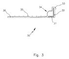
- the Fig. 3 shows a plaster profile 30, which has a cross-sectionally L-shaped or angular stiffening element 31 of a first material.
- the stiffening element 31 is formed of metal.
- the stiffening element 31 is completely surrounded by a second material 32.
- the plaster profile 30 has a profile edge 33.
- the surface 34 of the plaster profile 30 is structured in sections, which serves the better Putzverkrallung with the plaster profile 30.
- a fabric strip is indicated, which is arranged on the leg 36.
- the stiffening element 31 can be extruded into the remaining plaster profile 30.
- the embodiment of a plaster profile 40 of Fig. 4 is similar to the Fig. 3 ,
- the stiffening element 41 is in turn formed strip-shaped, as in the embodiments of Fig. 1 and 2 ,
- An additional stabilization of the plaster profile 40 is achieved in that it is equipped with a cavity 42.
- This means that the plaster profile 40 is at least partially formed as a hollow profile. Again, this is the
- a fabric strip 45 is provided on the leg 46.
Landscapes
- Engineering & Computer Science (AREA)
- Architecture (AREA)
- Civil Engineering (AREA)
- Structural Engineering (AREA)
- Extrusion Moulding Of Plastics Or The Like (AREA)
- Building Environments (AREA)
Abstract
Description
- Die Erfindung betrifft ein Putzprofil mit einem Aussteifungselement.
- Putzprofile, insbesondere solche aus Kunststoff, sind in verschiedenen Formen und Varianten bekannt. Ausschließlich aus Kunststoff hergestellte Putzprofile müssen, um eine gewisse Stabilität zu erreichen, mit dicken Schenkeln oder Abzugskanten hergestellt werden. Dies ist nachteilig bei dünnen Putzschichten, da dort keine ausreichende Überdeckung des Putzprofils erreicht wird und es dadurch zu Rissen oder Putzabplatzungen kommen kann. Derartige Kunststoffprofile sind zwar sehr kostengünstig herzustellen, jedoch instabil und labil.
- Aus der
DE 199 20 108 C2 ist eine Schnellputzleiste zum Abziehen ebener Putzflächen bekannt, mit einer durch eine Falte eines dünnwandigen Materialstreifens gebildeten, im Wesentlichen mittig angeordneten Abziehnase und mit zwei seitlich davon abstehenden Befestigungsschenkeln, wobei zumindest die seitlichen Befestigungsschenkel mit Lochungen versehen sind. Die Schnellputzleiste besteht aus Kunststoff. In die durch die ausgebogene Abziehnase gebildete Rinne ist ein in Längsrichtung der Schnellputzleiste durchlaufender Versteifungsstreifen eingelegt. Die Herstellung einer solchen Schnellputzleiste ist arbeitsaufwändig, da zunächst die Schnellputzleiste hergestellt und anschließend der Versteifungsstreifen eingelegt werden muss. Außerdem ist der Versteifungsstreifen nur klemmend gehalten und kann sich dadurch unter Umständen auch von der restlichen Schnellputzleiste lösen. Außerdem kann der Versteifungsstreifen, insbesondere, wenn er aus Blech hergestellt ist, korrodieren, da er lediglich in die Schnellputzleiste eingelegt ist. - Aufgabe der vorliegenden Erfindung ist es, ein verbessertes Putzprofil bereitzustellen.
- Gelöst wird diese Aufgabe erfindungsgemäß durch ein Putzprofil der eingangs genannten Art, wobei das Aussteifungselement aus einem ersten Material ausgebildet ist, welches umfangsmäßig von einem zweiten, anderen Material umgeben ist, wobei das Aussteifungselement in das zweite Material einextrudiert ist. Dabei ist das erste Material, also das Material des Aussteifungselements, vorzugsweise steifer ausgebildet als das zweite Material. Dadurch, dass das Aussteifungselement umfangsmäßig durch das zweite, andere Material umgeben ist, ist es vor äußeren Einflüssen geschützt angeordnet. Außerdem ist es zuverlässig an dem zweiten Material gehalten, da es vollständig von diesem umgeben ist. Das Aussteifungselement kann sich nicht unbeabsichtigt vom restlichen Putzprofil lösen. Das Aussteifungselement erstreckt sich vorzugsweise über die gesamte Länge des Putzprofils. Wenn das Aussteifungselement in das zweite Material einextrudiert ist, ist kein zusätzlicher Arbeitsschritt notwendig, um das Aussteifungselement mit dem restlichen Putzprofil zu verbinden. Wenn das Aussteifungselement ebenfalls extrudierbar ist, bzw. mittels Extrudieren hergestellt wird, ist es auch denkbar, das Aussteifungselement und das zweite Material zu koextrudieren, also das Putzprofil durch Koextrusion herzustellen. Insbesondere kann vorgesehen sein, dass das Aussteifungselement in einer und an einer bestimmten Position in das Putzprofil einextrudiert wird, damit es in der geforderten Belastungsrichtung das Putzprofil stabilisieren kann. Dies ist notwendig, damit an der Profilkante oder Abzugskante ein Werkzeug, wie z. B. eine Kelle oder eine Traufel, entlanggeführt werden kann, ohne dass das Putzprofil sich verbiegen oder nachgeben kann. Das erfindungsgemäße Putzprofil erlaubt daher, eine plane, ebene Putzfläche herzustellen.
- Gemäß einer bevorzugten Ausführungsform kann vorgesehen sein, dass das Aussteifungselement aus Metall ausgebildet ist. Durch ein Metall wird eine ausreichende Aussteifung erreicht. Es ist zwar grundsätzlich möglich, auch hier korrosionsbeständige Metalle zu verwenden, wie Aluminium oder Edelstahl, es ist jedoch auch möglich, lediglich Blech als Aussteifungselement zu verwenden, da dieses durch das zweite, andere Material vollständig ummantelt wird und somit vor äußeren Einflüssen und somit vor Korrosion geschützt ist. Bevorzugt ist jedoch die Verwendung von Aluminium, da dieses ein sehr leichtes Material ist.
- Vorteilhafterweise ist das zweite Material Kunststoff. Kunststoff ist einfach zu verarbeiten und formbar.
- Weitere Vorteile ergeben sich, wenn das Putzprofil eine Abzugsleiste aufweist, wobei das Aussteifungselement in der Abzugsleiste angeordnet ist. Dadurch wird das Putzprofil im Bereich der Abzugsleiste stabilisiert.
- Das Aussteifungselement kann unterschiedliche Formen aufweisen. Insbesondere kann es bandförmig, streifenförmig oder L-förmig ausgebildet sein. Bei einer L-förmigen Ausgestaltung können die das "L" bildenden Schenkel in einem Winkel 10 < α < 170° zueinander angeordnet sein. Vorzugsweise weisen sie einen Winkel von α = 90° zueinander auf. Auch ein quadratischer Querschnitt ist denkbar.
- Besonders bevorzugt ist es, wenn die Oberfläche des Putzprofils zumindest abschnittsweise zur besseren Putzverkrallung strukturiert ist.
- Gemäß einer Ausgestaltung der Erfindung kann vorgesehen sein, dass das Putzprofil als Hohlprofil ausgebildet ist. Auch durch diese Ausgestaltung kann das Putzprofil stabilisiert werden.
- Das Putzprofil kann einen oder mehrere aus Kunststoff ausgebildete Schenkel aufweisen. Dadurch kann das Putzprofil je nach Anwendungsgebiet entsprechend ausgebildet werden.
- Weitere Merkmale und Vorteile der Erfindung ergeben sich aus der nachfolgenden detaillierten Beschreibung eines Ausführungsbeispiels der Erfindung, anhand der Figuren der Zeichnung, die erfindungswesentliche Einzelheiten zeigen, sowie aus den Ansprüchen. Die einzelnen Merkmale können je einzeln für sich oder zu mehreren in beliebigen Kombinationen bei Varianten der Erfindung verwirklicht sein.
- In der schematischen Zeichnung sind Ausführungsbeispiele der Erfindung dargestellt, welche in der nachfolgenden Beschreibung näher erläutert werden.
- Es zeigen:
- Fig. 1
- eine erste Querschnittsdarstellung eines erfindungsgemäßen Putzprofils;
- Fig. 2
- eine Querschnittsdarstellung einer zweiten Ausführungsform eines erfindungsgemäßen Putzprofils;
- Fig. 3
- eine Querschnittsdarstellung einer dritten Ausführungsform eines Putzprofils;
- Fig.4
- eine Querschnittsdarstellung einer vierten Ausführungsform eines erfindungsgemäßen Putzprofils.
- Die
Fig. 1 zeigt ein Putzprofil 10, welches ein Aussteifungselement 11 aus einem ersten Material, insbesondere aus Metall, aufweist. Das Aussteifungselement 11 ist umfangsmäßig vollständig von einem zweiten, anderen Material 12 umgeben. Insbesondere wurde das Aussteifungselement 11 in das zweite Material 12 einextrudiert. Das Aussteifungselement 11 befindet sich in einer Abzugsleiste 13. Somit ist das Putzprofil 10 an der Stelle ausgesteift, an der die größte Belastung zu erwarten ist. An die Abzugsleiste 13 schließen sich zwei Schenkel 14, 15 an, die etwa orthogonal zueinander angeordnet sind. Zur Abzugsleiste 13 weisen sie jeweils einen Winkel von etwa 135° auf. Die Schenkel 14, 15 können beispielsweise im Eckbereich einer Wand angeordnet bzw. befestigt werden. Die Schenkel 14, 15 sind ebenfalls aus dem zweiten Material, insbesondere Kunststoff, ausgebildet. - In der
Fig. 2 ist eine zweite Ausführungsform eines Putzprofils 20 gezeigt. Das Putzprofil 20 weist wiederum ein Aussteifungselement 11 aus einem ersten Material auf, welches umfangsmäßig von einem zweiten Material 12 umgeben ist. Mit 13 ist wiederum eine Abzugsleiste bezeichnet. Beim Putzprofil 20 stehen Schenkel 21, 22 im Wesentlichen senkrecht von der Abzugsleiste 13 ab. Über die Schenkel 21, 22 kann das Putzprofil 20 beispielsweise an einer Wand befestigt werden. - Die
Fig. 3 zeigt ein Putzprofil 30, welches ein im Querschnitt L-förmiges bzw. winkelförmiges Aussteifungselement 31 aus einem ersten Material aufweist. Insbesondere ist das Aussteifungselement 31 aus Metall ausgebildet. Das Aussteifungselement 31 ist vollständig von einem zweiten Material 32 umgeben. Das Putzprofil 30 weist eine Profilkante 33 auf. Die Oberfläche 34 des Putzprofils 30 ist abschnittsweise strukturiert, was der besseren Putzverkrallung mit dem Putzprofil 30 dient. Durch kleine Erhebungen 35 ist ein Gewebestreifen angedeutet, der an dem Schenkel 36 angeordnet ist. Wie die Ausführungsformen der Putzprofile 10, 20 kann auch das Putzprofil 30 mittels Extrusion hergestellt werden. Insbesondere kann das Aussteifungselement 31 in das restliche Putzprofil 30 einextrudiert werden. - Die Ausführungsform eines Putzprofils 40 der
Fig. 4 ist ähnlich der derFig. 3 . Das Aussteifungselement 41 ist wiederum streifenförmig ausgebildet, wie in den Ausführungsbeispielen derFig. 1 und2 . Eine zusätzliche Stabilisierung des Putzprofils 40 wird dadurch erreicht, dass dieses mit einem Hohlraum 42 ausgestattet ist. Dies bedeutet, dass das Putzprofil 40 zumindest abschnittsweise als Hohlprofil ausgebildet ist. Auch hier ist die - Oberfläche 44 abschnittsweise strukturiert. Ein Gewebestreifen 45 ist an dem Schenkel 46 vorgesehen.
Claims (9)
- Putzprofil (10, 20, 30, 40) mit einem Aussteifungselement (11, 31, 41), dadurch gekennzeichnet, dass das Aussteifungselement (11, 31, 41) aus einem ersten Material ausgebildet ist, welches umfangsmäßig von einem zweiten, anderen Material (12, 32) umgeben ist, wobei das Aussteifungselement (11, 31, 41) in das zweite Material (12, 32) einextrudiert ist.
- Putzprofil nach Anspruch 1, dadurch gekennzeichnet, dass das Aussteifungselement (11, 31, 41) aus Metall ausgebildet ist.
- Putzprofil nach Anspruch 2, dadurch gekennzeichnet, dass das Aussteifungselement (11, 31, 41) aus Aluminium, Edelstahl, Blech oder dergleichen ausgebildet ist.
- Putzprofil nach einem der vorhergehenden Ansprüche, dadurch gekennzeichnet, dass das zweite Material (12, 32) Kunststoff ist.
- Putzprofil nach einem der vorhergehenden Ansprüche, dadurch gekennzeichnet, dass das Putzprofil (10, 20) eine Abzugsleiste (13) aufweist, wobei das Aussteifungselement (11) in der Abzugsleiste (13) angeordnet ist.
- Putzprofil nach einem der vorhergehenden Ansprüche, dadurch gekennzeichnet, dass das Aussteifungselement (11, 31, 41) bandförmig, streifenförmig oder L-förmig ausgebildet ist.
- Putzprofil nach einem der vorhergehenden Ansprüche, dadurch gekennzeichnet, dass dessen Oberfläche (34, 44) zumindest abschnittsweise zur besseren Putzverkrallung strukturiert ist.
- Putzprofil nach einem der vorhergehenden Ansprüche, dadurch gekennzeichnet, dass dieses als Hohlprofil ausgebildet ist.
- Putzprofil nach einem der vorhergehenden Ansprüche, dadurch gekennzeichnet, dass dieses einen oder mehrere aus Kunststoff ausgebildete Schenkel (14, 15, 21, 22) aufweist.
Applications Claiming Priority (1)
| Application Number | Priority Date | Filing Date | Title |
|---|---|---|---|
| DE200920007375 DE202009007375U1 (de) | 2009-05-22 | 2009-05-22 | Putzprofil mit Aussteifungselement |
Publications (2)
| Publication Number | Publication Date |
|---|---|
| EP2253775A2 true EP2253775A2 (de) | 2010-11-24 |
| EP2253775A3 EP2253775A3 (de) | 2012-09-05 |
Family
ID=40936846
Family Applications (1)
| Application Number | Title | Priority Date | Filing Date |
|---|---|---|---|
| EP10004505A Withdrawn EP2253775A3 (de) | 2009-05-22 | 2010-04-29 | Putzprofil mit Aussteifungselement |
Country Status (2)
| Country | Link |
|---|---|
| EP (1) | EP2253775A3 (de) |
| DE (1) | DE202009007375U1 (de) |
Families Citing this family (1)
| Publication number | Priority date | Publication date | Assignee | Title |
|---|---|---|---|---|
| DE202020100740U1 (de) | 2020-02-12 | 2020-03-17 | Vws-Befestigungstechnik Gmbh | Schnellputzprofil |
Citations (1)
| Publication number | Priority date | Publication date | Assignee | Title |
|---|---|---|---|---|
| DE19920108C2 (de) | 1999-05-03 | 2003-03-06 | Gima Gipser Und Malerbedarf Gm | Schnellputzleiste |
Family Cites Families (2)
| Publication number | Priority date | Publication date | Assignee | Title |
|---|---|---|---|---|
| GB9019000D0 (en) * | 1990-08-31 | 1990-10-17 | Expanded Metal Company The Lim | Plaster bead |
| DE10316022A1 (de) * | 2003-04-07 | 2004-11-04 | Rehau Ag + Co. | Winkelprofil |
-
2009
- 2009-05-22 DE DE200920007375 patent/DE202009007375U1/de not_active Expired - Lifetime
-
2010
- 2010-04-29 EP EP10004505A patent/EP2253775A3/de not_active Withdrawn
Patent Citations (1)
| Publication number | Priority date | Publication date | Assignee | Title |
|---|---|---|---|---|
| DE19920108C2 (de) | 1999-05-03 | 2003-03-06 | Gima Gipser Und Malerbedarf Gm | Schnellputzleiste |
Also Published As
| Publication number | Publication date |
|---|---|
| EP2253775A3 (de) | 2012-09-05 |
| DE202009007375U1 (de) | 2009-08-06 |
Similar Documents
| Publication | Publication Date | Title |
|---|---|---|
| EP3299199B1 (de) | Dichtungsstrang zur bildung einer dichtung an einer fahrzeugkarosserie | |
| DE202009018128U1 (de) | Winkelprofil | |
| EP0016958B1 (de) | Rahmenprofil für ein Fenster, eine Tür od. dgl. | |
| EP2253775A2 (de) | Putzprofil mit Aussteifungselement | |
| DE202009004158U1 (de) | Aufprallelement sowie Verwendung eines Einlegers für einen Träger eines Aufprallelementes | |
| EP1705046B1 (de) | Extrudierter Dichtungsstrang | |
| EP2764177B1 (de) | Hohlprofil | |
| EP2191743A2 (de) | Regalauflage | |
| EP2746487B1 (de) | Winkelprofil | |
| EP3865640A1 (de) | Putzprofil | |
| DE102010015117A1 (de) | Isolierglasscheibe | |
| EP2196081B1 (de) | Sieb | |
| EP1905919A2 (de) | Sockelabschlussprofil | |
| DE202005012326U1 (de) | Entwässerungsvorrichtung | |
| EP1703036A1 (de) | Bauelement zur Schub- bzw. Durchstanzbewehrung | |
| DE102012014790A1 (de) | Montageschiene sowie Verfahren zu deren Herstellung | |
| AT409999B (de) | Tor | |
| LU502438B1 (de) | Profilrahmensysteme für schiebeelemente | |
| EP2378045A2 (de) | Isolierglasscheibe | |
| DE102009036925A1 (de) | Verfahren zur Herstellung einer Gewebeprofilleiste | |
| DE202005009527U1 (de) | Sockelabschlussprofil | |
| EP1719853B1 (de) | Kantenschutzprofil | |
| EP2607599A1 (de) | Hohlprofil für einen Rahmen | |
| DE202005014065U1 (de) | Gewebestreifen | |
| DE202004016692U1 (de) | Faschenprofil |
Legal Events
| Date | Code | Title | Description |
|---|---|---|---|
| PUAI | Public reference made under article 153(3) epc to a published international application that has entered the european phase |
Free format text: ORIGINAL CODE: 0009012 |
|
| AK | Designated contracting states |
Kind code of ref document: A2 Designated state(s): AT BE BG CH CY CZ DE DK EE ES FI FR GB GR HR HU IE IS IT LI LT LU LV MC MK MT NL NO PL PT RO SE SI SK SM TR |
|
| AX | Request for extension of the european patent |
Extension state: AL BA ME RS |
|
| PUAL | Search report despatched |
Free format text: ORIGINAL CODE: 0009013 |
|
| AK | Designated contracting states |
Kind code of ref document: A3 Designated state(s): AT BE BG CH CY CZ DE DK EE ES FI FR GB GR HR HU IE IS IT LI LT LU LV MC MK MT NL NO PL PT RO SE SI SK SM TR |
|
| AX | Request for extension of the european patent |
Extension state: AL BA ME RS |
|
| RIC1 | Information provided on ipc code assigned before grant |
Ipc: E04F 19/02 20060101ALI20120801BHEP Ipc: E04F 13/06 20060101AFI20120801BHEP |
|
| STAA | Information on the status of an ep patent application or granted ep patent |
Free format text: STATUS: THE APPLICATION IS DEEMED TO BE WITHDRAWN |
|
| 18D | Application deemed to be withdrawn |
Effective date: 20130306 |