EP2251296A1 - Flurförderzeug mit integriertem Ladegerät - Google Patents
Flurförderzeug mit integriertem Ladegerät Download PDFInfo
- Publication number
- EP2251296A1 EP2251296A1 EP10004623A EP10004623A EP2251296A1 EP 2251296 A1 EP2251296 A1 EP 2251296A1 EP 10004623 A EP10004623 A EP 10004623A EP 10004623 A EP10004623 A EP 10004623A EP 2251296 A1 EP2251296 A1 EP 2251296A1
- Authority
- EP
- European Patent Office
- Prior art keywords
- retaining ring
- ring
- charging cable
- truck
- connector
- Prior art date
- Legal status (The legal status is an assumption and is not a legal conclusion. Google has not performed a legal analysis and makes no representation as to the accuracy of the status listed.)
- Granted
Links
Images


Classifications
-
- B—PERFORMING OPERATIONS; TRANSPORTING
- B66—HOISTING; LIFTING; HAULING
- B66F—HOISTING, LIFTING, HAULING OR PUSHING, NOT OTHERWISE PROVIDED FOR, e.g. DEVICES WHICH APPLY A LIFTING OR PUSHING FORCE DIRECTLY TO THE SURFACE OF A LOAD
- B66F9/00—Devices for lifting or lowering bulky or heavy goods for loading or unloading purposes
- B66F9/06—Devices for lifting or lowering bulky or heavy goods for loading or unloading purposes movable, with their loads, on wheels or the like, e.g. fork-lift trucks
- B66F9/075—Constructional features or details
- B66F9/07513—Details concerning the chassis
- B66F9/07531—Battery compartments
-
- H—ELECTRICITY
- H02—GENERATION; CONVERSION OR DISTRIBUTION OF ELECTRIC POWER
- H02G—INSTALLATION OF ELECTRIC CABLES OR LINES, OR OF COMBINED OPTICAL AND ELECTRIC CABLES OR LINES
- H02G11/00—Arrangements of electric cables or lines between relatively-movable parts
-
- H—ELECTRICITY
- H02—GENERATION; CONVERSION OR DISTRIBUTION OF ELECTRIC POWER
- H02G—INSTALLATION OF ELECTRIC CABLES OR LINES, OR OF COMBINED OPTICAL AND ELECTRIC CABLES OR LINES
- H02G3/00—Installations of electric cables or lines or protective tubing therefor in or on buildings, equivalent structures or vehicles
- H02G3/02—Details
- H02G3/04—Protective tubing or conduits, e.g. cable ladders or cable troughs
- H02G3/0462—Tubings, i.e. having a closed section
- H02G3/0481—Tubings, i.e. having a closed section with a circular cross-section
-
- H—ELECTRICITY
- H02—GENERATION; CONVERSION OR DISTRIBUTION OF ELECTRIC POWER
- H02G—INSTALLATION OF ELECTRIC CABLES OR LINES, OR OF COMBINED OPTICAL AND ELECTRIC CABLES OR LINES
- H02G3/00—Installations of electric cables or lines or protective tubing therefor in or on buildings, equivalent structures or vehicles
- H02G3/02—Details
- H02G3/08—Distribution boxes; Connection or junction boxes
- H02G3/18—Distribution boxes; Connection or junction boxes providing line outlets
Definitions
- the present invention relates to an industrial truck with an integrated charger, which can be connected via an on or in the truck entrained charging cable with connector to an electrical power supply.
- Trucks with built-in battery charger can be directly connected to the usual mains supply with a suitable cable.
- the respective connector must be easily accessible on the truck for this purpose.
- the cable should be able to be stowed inside the vehicle for trouble-free operation of the truck, without tangling the charging cable or making the connector inside the vehicle difficult to find.
- trucks with built-in battery charger is also to be considered that during the assembly of the truck, the charger with the associated power cord and its country-specific connector is installed very early.
- the charging cable must only be routed through the cladding when later installing the cladding.
- the invention has for its object to provide a truck with an integrated charger, in which a connector for the entrained on or in the truck charging cable is held by simple means and subsequent assembly of the connector is avoided on the charging cable.
- the truck according to the invention is equipped with an electric charger, which can be connected via a connected to or in the truck charging cable with connector to an electrical power supply.
- the charger connected to the electrical power supply can then recharge a battery on the truck.
- the charging cable is routed to the outside via an opening in the vehicle trim.
- a retaining ring is detachably inserted into the opening in the vehicle trim panel, the annular opening of which has a diameter which holds the plug connector of the charging cable guided through the ring opening in the retaining ring.
- the retaining ring is adapted to be opened so that the charging cable can be passed through the retaining ring without disconnecting the connector from the charging cable.
- the retaining ring inserted into the opening in the vehicle trim holds according to the invention the electrical connector, wherein the charging cable is passed through the retaining ring.
- the retaining ring When inserted, the retaining ring is closed.
- the retaining ring has the advantage that the connector can be held in an easily accessible position of the truck and is ready to connect the truck to the electrical power supply for a user of the truck. Further, the retaining ring ensures that the charging cable disposed in the truck can not knot, since both ends of the charging cable are fixed, one end to the charger, one end in the retaining ring. Even with the assembly of the truck, the retaining ring creates a considerable amount of work, since the charger with charging cable mounted directly to its connector and the charging cable can be inserted into the open retaining ring.
- the retaining ring consists of two elements which are detachably connected to each other.
- the advantage of this embodiment is also that the retaining ring from the opening in the vehicle trim can be removed is, its ring elements can be opened and so can be placed on the charging cable.
- the retaining ring consists of two ring elements, which are designed as identical parts.
- the design as identical identical parts allows that it is not necessary to distinguish between different ring elements during assembly, but that any two ring elements can be assembled to form the retaining ring.
- the ring elements are connected together by connecting means along the circumference of the retaining ring.
- the connection means may be, for example, snap or click connections. It is also conceivable that the ring elements are connected to each other via a hinge, so that the retaining ring can be opened without removing the ring elements from each other.
- the ring elements as connecting means each have pins and holes which are arranged in a contact surface of the ring elements.
- the ring elements form the retaining ring, wherein the ring elements abut each other along their two contact surfaces.
- each ring element has at least one protruding pin and a corresponding bore.
- the pin of one ring element dips into the corresponding bore of the other ring element.
- the retaining ring has an inner wall which has a circumferential shoulder.
- the position of the paragraph within the retaining ring can be adapted so that an inserted into the retaining ring Plug connector rests with its pointing to the charging cable end of the paragraph in the retaining ring and partially protruding from the retaining ring.
- the inner wall of the retaining ring above the shoulder on the outwardly facing side elastic tongues which carry on its radially outwardly facing side locking projections to hold the retaining ring in the opening of the vehicle trim.
- the locking projections engage behind in the assembled state of the retaining ring corresponding projections in the vehicle trim.
- Fig. 1 shows a retaining ring 10 according to the invention, which consists of two ring elements 12 and 14.
- the retaining ring 10 has a total of a cylindrical shape, which is waisted in the middle.
- At the end of the retaining ring 10 has an upper peripheral edge 16 which forms an outwardly projecting shoulder 17.
- the inner wall of the retaining ring 10 is rotationally symmetrical in shape and forms an inwardly projecting shoulder 18.
- the pointing away from the upper edge 16 end 19 of the retaining ring widens funnel-shaped.
- the wall 20 of the retaining ring 10 is at the lower end, which is the upper edge 16 opposite, radially outward.
- a latching tongue 22 is formed centrally.
- the latching tongue 22 extends in the axial direction of the retaining ring 10 and is separated from the inner wall by a substantially U-shaped section 26.
- the latching tongue 22 rises in the region of the shoulder 18 and extends below the upper edge 16.
- a latching lug 24 is provided at the free end, which projects outwardly beyond the lateral surface of the retaining ring.
- the latching tongue 22 is respectively provided centrally in the ring member 12 and 14.
- each ring element has two further latching tongues 30 in the area of its contact surface.
- the further latching tongues 30 of the adjoining ring elements 12 and 14 form a common latching tongue whose width is approximately equal to the width the central latching tongue 22 corresponds.
- the further latching tongue 30 is in each case separated from the inner wall of the ring element by an L-shaped cut 32.
- the other locking tongues each have an outwardly projecting locking lug 34 which is disposed below the upper edge 16.
- the latching tongues 22, 30 and the latching lugs 24, 34 are designed so that, when the mounting position is correct, a smooth and interrupted only by the cuts 26, 32 inner surface of the ring. A not fully engaged tongue 22 or 30 and thus a not correctly mounted ring can be seen immediately from the outside of the inwardly projecting locking tongues. By simply pressing the ring or individual locking tongues the correct installation position can be produced.
- each ring member on one side two pins 36, one of which is disposed above the locking lug 34 and the other is provided in the funnel-shaped flared lower end of the ring member 12.
- the other side of each ring element is provided with corresponding holes 38 whose diameter corresponds to the diameter of the pin 36.
- Pin 36 and bore 38 are provided correspondingly on the second contact surface of the ring member 12.
- Ring element 12 and ring element 14 are formed as identical parts, d. H. both parts are identically shaped. Accordingly, when the ring element 12 and the ring element 14 are assembled, the pins 36 strike opposite holes 38 in the ring element 14, and the holes 38 in the ring element 12 receive opposite pins 36 of the ring element 14.
- Fig. 3 shows the element according to the invention in the cut form. How clearly in Fig. 3 To recognize, the ring member has a substantially cup-shaped contour, wherein the lower portion of the retaining ring funnel-shaped in the region 19th the wall 20 expands.
- the retaining ring 10 in Fig. 3 is inserted into a recess of the vehicle panel 40.
- the edge 16 is in a circumferential projection 41 on the vehicle trim and is secured by the locking lugs 24 and 34 below the projection 41 in the vehicle trim.
- the angle of the oblique annular contact surface between the top of the locking lugs and the panel is chosen so that the locking tongues do not push inward at higher tensile loads and solve the ring from the panel or laterally spread and break, as in an approximately radially to the ring element lying surface could be the case.
- Fig. 4 shows a truck 42 with a mast 44 and a load carriage with forks 46.
- the battery and the charger are covered by a vehicle panel 48.
- a trough 50 is formed on the upper side, in the bottom of the retaining ring 10 is inserted.
- Fig. 5 shows the truck 42 in a plan view from above, in which the rectangular trough 50 is shown with the retaining ring 10.
- Under the vehicle panel 48 is an electric battery to power the truck and a charger, with which the battery can be recharged.
- Battery and charger are not necessarily located under the same panel or not in the same space.
- the power cord from an exit point in the battery compartment trim is performed, but it can be performed by other trim parts, such as the front hood to the outside ..
- the connector arranged during normal use of the truck in the retaining ring 10, wherein the charging cable to the charger then concealed within the truck by the vehicle trim.
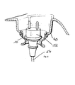
- Fig. 6 shows the inserted into the panel 40 retaining ring 10, in which a connector 52 is held.
- the charging cable 54 to the connector 52 is guided by the retaining ring 10.
Landscapes
- Engineering & Computer Science (AREA)
- Transportation (AREA)
- Structural Engineering (AREA)
- Civil Engineering (AREA)
- Life Sciences & Earth Sciences (AREA)
- Geology (AREA)
- Mechanical Engineering (AREA)
- Electric Propulsion And Braking For Vehicles (AREA)
Abstract
Description
- Die vorliegende Erfindung betrifft ein Flurförderzeug mit einem integrierten Ladegerät, das über ein an oder in dem Flurförderzeug mitgeführtes Ladekabel mit Steckverbinder an eine elektrische Stromversorgung anschließbar ist.
- Flurförderzeuge mit eingebautem Batterieladegerät können mit einem entsprechenden Kabel direkt an die übliche Netzstromversorgung angeschlossen werden. Der jeweilige Steckverbinder muss zu diesem Zweck leicht zugänglich an dem Flurförderzeug angeordnet sein. Das Kabel sollte für einen reibungsfreien Betrieb des Flurförderzeugs im Fahrzeuginneren verstaut werden können, ohne dass das Ladekabel sich verheddert oder der Steckverbinder im Fahrzeuginnern schwer auffindbar ist. Bei Flurförderzeugen mit eingebautem Batterieladegerät ist ferner zu berücksichtigen, dass bei der Montage des Flurförderzeugs das Ladegerät mit dem damit verbundenen Netzkabel und seinem landesspezifischen Steckverbinder bereits sehr früh verbaut wird. Erst bei der späteren Montage der Verkleidung muss das Ladekabel durch die Verkleidung geführt werden.
- Der Erfindung liegt die Aufgabe zugrunde, ein Flurförderzeug mit einem integrierten Ladegerät bereitzustellen, bei dem ein Steckverbinder für das an oder in dem Flurförderzeug mitgeführte Ladekabel mit einfachen Mitteln gehalten ist und eine nachträgliche Montage des Steckverbinders an dem Ladekabel vermieden wird.
- Erfmdungsgemäß wird die Aufgabe durch ein Flurförderzeug mit den Merkmalen aus Anspruch 1 gelöst. Vorteilhafte Ausgestaltungen bilden den Gegenstand der Unteransprüche.
- Das erfindungsgemäße Flurförderzeug ist mit einem elektrischen Ladegerät ausgestattet, das über ein an oder in dem Flurförderzeug mitgeführtes Ladekabel mit Steckverbinder an eine elektrische Stromversorgung anschließbar ist. Das an die elektrische Stromversorgung angeschlossene Ladegerät kann dann eine Batterie an dem Flurförderzeug wieder aufladen. Das Ladekabel ist über eine Öffnung in der Fahrzeugverkleidung nach außen geführt. Erfmdungsgemäß ist in die Öffnung in der Fahrzeugverkleidung ein Haltering lösbar eingesetzt, dessen Ringöffnung einen Durchmesser aufweist, der den Steckverbinder des durch die Ringöffnung geführten Ladekabels in dem Haltering hält. Der Haltering ist ausgebildet, um geöffnet zu werden, so dass das Ladekabel durch den Haltering geführt werden kann, ohne den Steckverbinder vom Ladekabel zu trennen. Der in die Öffnung in der Fahrzeugverkleidung eingesetzte Haltering hält erfindungsgemäß den elektrischen Steckverbinder, wobei das Ladekabel durch den Haltering geführt ist. Im eingesetzten Zustand ist der Haltering geschlossen. Der Haltering besitzt den Vorteil, dass der Steckverbinder an einer gut zugänglichen Position des Flurförderzeugs gehalten werden kann und zum Anschluss des Flurförderzeugs an die elektrische Stromversorgung für einen Benutzer des Flurförderzeugs griffbereit ist. Ferner stellt der Haltering sicher, dass das in dem Flurförderzeug angeordnete Ladekabel sich nicht verknoten kann, da beide Enden des Ladekabels fixiert sind, ein Ende an dem Ladegerät, ein Ende in dem Haltering. Auch bei der Montage des Flurförderzeugs schafft der Haltering eine erhebliche Arbeitserleichterung, da das Ladegerät mit Ladekabel direkt mit seinem Steckverbinder montiert und das Ladekabel in den geöffneten Haltering eingeführt werden kann.
- In einer bevorzugten Ausgestaltung besteht der Haltering aus zwei Elementen, die lösbar miteinander verbunden sind. Der Vorteil dieser Ausgestaltung liegt zudem darin, dass der Haltering aus der Öffnung in der Fahrzeugverkleidung entnehmbar ist, seine Ringelemente geöffnet werden können und so auf das Ladekabel aufgesetzt werden kann.
- In einer bevorzugten Ausgestaltung besteht der Haltering aus zwei Ringelementen, die als Gleichteile ausgebildet sind. Die Ausbildung als identische Gleichteile erlaubt es, dass bei der Montage nicht zwischen unterschiedlichen Ringelementen unterschieden werden muss, sondern dass zwei beliebige Ringelemente zusammengesetzt werden können, um den Haltering zu bilden.
- In einer bevorzugten Ausgestaltung sind die Ringelemente durch Verbindungsmittel entlang dem Umfang des Halterings miteinander verbunden. Bei den Verbindungsmitteln kann es sich beispielsweise um Schnapp- oder Klickverbindungen handeln. Auch ist es denkbar, dass die Ringelemente über ein Gelenk miteinander verbunden sind, sodass der Haltering geöffnet werden kann, ohne die Ringelemente voneinander zu entfernen.
- Bevorzugt weisen die Ringelemente als Verbindungsmittel jeweils Zapfen und Bohrungen auf, die in einer Kontaktfläche der Ringelemente angeordnet sind. Im zusammengesetzten Zustand bilden die Ringelemente den Haltering, wobei die Ringelemente entlang ihrer zwei Kontaktflächen aneinander anliegen. In dieser Kontaktfläche besitzt jedes Ringelement mindestens einen vorstehenden Zapfen und eine entsprechende Bohrung. Im zusammengesetzten Zustand taucht der Zapfen des einen Ringelements in die entsprechende Bohrung des anderen Ringelements ein.
- Um eine gute Haltefunktion für den Steckverbinder in dem Haltering bereitzustellen, hat es sich als vorteilhaft herausgestellt, dass der Haltering eine Innenwand aufweist, die einen umlaufenden Absatz besitzt. Die Position des Absatzes innerhalb des Halterings kann dabei so angepasst sein, dass ein in den Haltering eingesetzter Steckverbinder mit seinem zum Ladekabel weisenden Ende an den Absatz in dem Haltering anliegt und teilweise aus dem Haltering vorsteht.
- In einer bevorzugten Ausgestaltung weist die Innenwand des Halterings oberhalb des Absatzes auf der nach außen weisenden Seite elastische Zungen auf, die auf ihrer radial nach außen weisenden Seite Rastvorsprünge tragen, um den Haltering in der Öffnung der Fahrzeugverkleidung zu halten. Die Rastvorsprünge hintergreifen im montiertem Zustand des Halterings entsprechende Vorsprünge in der Fahrzeugverkleidung.
- Die Erfindung wird nachfolgend anhand eines Ausführungsbeispiels näher erläutert. Es zeigt:
- Fig. 1
- den Haltering in seiner zusammengesetzten Form in einer perspek- tivischen Ansicht,
- Fig. 2
- den Haltering mit seinen beiden Ringelementen in einer auseinander- gezogenen Position,
- Fig. 3
- den in die Fahrzeugverkleidung eingesetzten Haltering in einer Schnitt- ansicht,
- Fig. 4
- eine perspektivische Ansicht eines Flurförderzeugs mit einem Haltering (teilweise verdeckt),
- Fig. 5
- eine Aufsicht auf das Flurförderzeug aus
Fig. 4 von oben mit einem Blick auf den Haltering, - Fig. 6
- einen eingebauten Haltering mit Steckverbinder in einer geschnittenen Ansicht.
-
Fig. 1 zeigt einen erfindungsgemäßen Haltering 10, der aus zwei Ringelementen 12 und 14 besteht. Der Haltering 10 besitzt insgesamt eine zylindrische Form, die in der Mitte tailliert ist. An dem Ende besitzt der Haltering 10 einen oberen umlaufenden Rand 16, der einen nach außen vorspringenden Absatz 17 bildet. Die Innenwand des Halterings 10 ist rotationssymmetrisch geformt und bildet einen nach innen vorstehenden Absatz 18. Das von dem oberen Rand 16 fortweisende Ende 19 des Halterings erweitert sich trichterförmig. Die Wand 20 des Halterings 10 steht an dem unteren Ende, das dem oberen Rand 16 gegenüber liegt, radial nach außen ab. - In der Innenwand des Halterings ist mittig eine Rastzunge 22 ausgebildet. Die Rastzunge 22 erstreckt sich in axialer Richtung des Halterings 10 und ist durch einen im Wesentlichen U-förmigen Schnitt 26 von der Innenwand getrennt. Die Rastzunge 22 entspringt im Bereich des Absatzes 18 und erstreckt sich bis unterhalb des oberen Randes 16. An der Außenseite der Rastzunge 22 ist an deren freiem Ende eine Rastnase 24 vorgesehen, die nach außen über die Mantelfläche des Halterings vorsteht. Die Rastzunge 22 ist jeweils mittig in dem Ringelement 12 und 14 vorgesehen.
- Nachfolgend mit Bezug auf
Fig. 2 : Neben der zentralen Rastzunge 22 besitzt jedes Ringelement im Bereich seiner Kontaktfläche 28 zwei weitere Rastzungen 30. Im zusammengesetzten Zustand der Ringelemente 12 und 14 bilden die weiteren Rastzungen 30 der aneinander angrenzenden Ringelemente 12 und 14 eine gemeinsame Rastzunge, die in ihrer Breite ungefähr der Breite der zentralen Rastzunge 22 entspricht. Die weitere Rastzunge 30 ist jeweils von der Innenwand des Ringelements durch einen L-förmigen Schnitt 32 getrennt. Auch die weiteren Rastzungen besitzen jeweils eine außen vorstehende Rastnase 34, die unterhalb des oberen Randes 16 angeordnet ist. - Die Rastzungen 22, 30 und die Rastnasen 24, 34 sind so ausgestaltet, dass sich bei korrekter Einbaulage wieder eine glatte und nur durch die Schnitte 26, 32 unterbrochene Innenfläche des Ringes ergibt. Eine nicht vollständig eingerastete Zunge 22 oder 30 und somit ein nicht korrekt montierter Ring sind sofort von außen an den nach innen überstehenden Rastzungen zu erkennen. Durch einfaches Nachdrücken des Ringes oder einzelner Rastzungen kann die korrekte Einbaulage hergestellt werden.
- In der Kontaktfläche 28 besitzt jedes Ringelement auf einer Seite zwei Zapfen 36, von denen einer oberhalb der Rastnase 34 angeordnet und der andere in dem trichterförmig sich erweiternden unteren Ende des Ringelements 12 vorgesehen ist. Die andere Seite jedes Ringelements ist mit entsprechenden Bohrungen 38 versehen, deren Durchmesser dem Durchmesser des Zapfens 36 entspricht. Zapfen 36 und Bohrung 38 sind entsprechend an der zweiten Kontaktfläche des Ringelements 12 vorgesehen.
- Ringelement 12 und Ringelement 14 sind als Gleichteile ausgebildet, d. h. beide Teile sind identisch geformt. Dementsprechend treffen bei einem Zusammensetzen von Ringelement 12 und Ringelement 14 die Zapfen 36 auf gegenüberliegende Bohrungen 38 in dem Ringelement 14 und die Bohrungen 38 in dem Ringelement 12 nehmen gegenüberliegende Zapfen 36 des Ringelements 14 auf.
-
Fig. 3 zeigt das erfindungsgemäße Element in der geschnittenen Form. Wie deutlich inFig. 3 zu erkennen, besitzt das Ringelement eine im Wesentlichen kelchförmige Kontur, wobei sich der untere Bereich des Halterings trichterförmig im Bereich 19 der Wand 20 erweitert. Der Haltering 10 inFig. 3 ist in eine Ausnehmung der Fahrzeugverkleidung 40 eingesetzt. Zum sicheren Halt des Halterings in der Fahrzeugverkleidung liegt der Rand 16 in einem umlaufenden Vorsprung 41 an der Fahrzeugverkleidung auf und wird durch die Rastnasen 24 und 34 unterhalb des Vorsprungs 41 in der Fahrzeugverkleidung gesichert. - Der Winkel der schrägen ringförmigen Kontaktfläche zwischen der Oberseite der Rastnasen und der Verkleidung ist so gewählt, dass sich die Rastzungen bei höheren Zugbelastungen nicht nach innen schieben und den Ring aus der Verkleidung lösen oder seitlich aufspreizen und abbrechen, wie es bei einer annähernd radial zum Ringelement liegenden Fläche der Fall sein könnte. Dadurch wird auch beim Zug an einem beispielsweise unterhalb des Ringes verknoteten Kabel der sichere Halt des Ringes in der Verkleidung weitestgehend sichergestellt.
-
Fig. 4 zeigt ein Flurförderzeug 42 mit einem Mast 44 und einen Lastschlitten mit Gabeln 46. Die Batterie und das Ladegerät sind durch eine Fahrzeugverkleidung 48 abgedeckt. In der Fahrzeugverkleidung 48 ist auf der oberen Seite eine Mulde 50 ausgeformt, in deren Boden der Haltering 10 eingesetzt ist.Fig. 5 zeigt das Flurförderzeug 42 in einer Aufsicht von oben, in der die rechteckige Mulde 50 mit dem Haltering 10 dargestellt ist. - Unter der Fahrzeugverkleidung 48 befindet sich eine elektrische Batterie zur Versorgung des Flurförderzeugs sowie ein Ladegerät, mit dem die Batterie wieder aufgeladen werden kann. Batterie und Ladegerät sind nicht notwendig unter der selben Verkleidung bzw. nicht im selben Bauraum angeordnet. In dem dargestellten Ausführungsbeispiel wird das Netzkabel aus einer Austrittsstelle in der Batterieraumverkleidung geführt, es kann aber durch andere Verkleidungsteile, wie beispielsweise die Fronthaube nach außen geführt werden.. Der Steckverbinder ist beim regulären Gebrauch des Flurförderzeugs in dem Haltering 10 angeordnet, wobei das Ladekabel zu dem Ladegerät sodann innerhalb des Flurförderzeugs durch die Fahrzeugverkleidung verdeckt verläuft.
-
Fig. 6 zeigt den in die Verkleidung 40 eingesetzten Haltering 10, in dem ein Steckverbinder 52 gehalten ist. Das Ladekabel 54 zu dem Steckverbinder 52 ist dabei durch den Haltering 10 geführt.
Claims (7)
- Flurförderzeug mit einem integrierten Ladegerät, das über ein an oder in dem Flurförderzeug mitgeführtes Ladekabel mit Steckverbinder an ein elektrisches Stromversorgungsnetz anschließbar ist, wobei das Ladekabel über eine Öffnung in der Fahrzeugverkleidung nach außen geführt ist, dadurch gekennzeichnet, dass in der Öffnung ein Haltering (10) lösbar eingesetzt ist, dessen Ringöffnung einen Durchmesser aufweist, der den Steckverbinder des durch die Ringöffnung geführten Ladekabels in dem Haltering (10) hält, wobei der Haltering geöffnet werden kann, um das Ladekabel durch den Haltering zu führen.
- Flurförderzeug nach Anspruch 1, dadurch gekennzeichnet, dass der Haltering zwei Ringelemente (12, 14) aufweist, die lösbar miteinander verbunden sind.
- Flurförderzeug nach Anspruch 2, dadurch gekennzeichnet, dass die Ringelemente (12, 14) als Gleichteile ausgebildet sind.
- Flurförderzeug nach Anspruch 2 oder 3, dadurch gekennzeichnet, dass die Ringelemente (12, 14) über Verbindungsmittel (36, 38) entlang dem Umfang des Halterings miteinander verbunden sind.
- Flurförderzeug nach Anspruch 4, dadurch gekennzeichnet, dass die Ringelemente (12, 14) als Verbindungselement Zapfen (36) und Bohrungen (38) aufweisen, die in einer Kontaktfläche (28) der Ringelemente (12, 14) angeordnet sind.
- Flurförderzeug nach einem der Ansprüche 1 - 5, dadurch gekennzeichnet, dass der Haltering (10) eine Innenwand aufweist, die einen umlaufenden Absatz (18) besitzt.
- Flurförderzeug nach Anspruch 6, dadurch gekennzeichnet, dass die Innenwand oberhalb des Absatzes (18) auf der zum Steckverbinder weisenden Seite elastische Zungen (22, 30) aufweist, die auf der nach außen liegenden Seite Rastnasen (24, 34) tragen, um den Haltering in der Öffnung der Fahrzeugverkleidung zu halten.
Applications Claiming Priority (1)
| Application Number | Priority Date | Filing Date | Title |
|---|---|---|---|
| DE200910021274 DE102009021274A1 (de) | 2009-05-11 | 2009-05-11 | Flurförderzeug mit integriertem Ladegerät |
Publications (2)
| Publication Number | Publication Date |
|---|---|
| EP2251296A1 true EP2251296A1 (de) | 2010-11-17 |
| EP2251296B1 EP2251296B1 (de) | 2012-09-19 |
Family
ID=42556694
Family Applications (1)
| Application Number | Title | Priority Date | Filing Date |
|---|---|---|---|
| EP20100004623 Active EP2251296B1 (de) | 2009-05-11 | 2010-05-03 | Flurförderzeug mit integriertem Ladegerät |
Country Status (3)
| Country | Link |
|---|---|
| EP (1) | EP2251296B1 (de) |
| DE (1) | DE102009021274A1 (de) |
| ES (1) | ES2395869T3 (de) |
Families Citing this family (1)
| Publication number | Priority date | Publication date | Assignee | Title |
|---|---|---|---|---|
| DE102018101529A1 (de) * | 2018-01-24 | 2019-07-25 | Jungheinrich Aktiengesellschaft | Flurförderzeug mit einem elektrischen Steckverbinder |
Citations (5)
| Publication number | Priority date | Publication date | Assignee | Title |
|---|---|---|---|---|
| US4616872A (en) * | 1984-11-28 | 1986-10-14 | Kubota, Ltd. | Earth moving vehicle |
| EP0983960A1 (de) * | 1998-09-02 | 2000-03-08 | Crown Gabelstapler GmbH | Gabelhubwagen mit Batterien und intergriertem Ladegerät |
| JP2003073099A (ja) * | 2001-09-05 | 2003-03-12 | Nippon Yusoki Co Ltd | バッテリ式フォークリフト |
| GB2418899A (en) * | 2004-10-08 | 2006-04-12 | Linde Material Handling | Industrial truck with maintenance opening |
| EP1925587A1 (de) * | 2006-11-23 | 2008-05-28 | Jungheinrich Aktiengesellschaft | Anordnung eines Servicesteckers bzw. einer -steckbuchse im Gehäuse eines Flurförderzeugs |
Family Cites Families (2)
| Publication number | Priority date | Publication date | Assignee | Title |
|---|---|---|---|---|
| DE202006016839U1 (de) * | 2005-11-02 | 2007-03-15 | Tempelmann, Herbert | Ladestation |
| DE202007001040U1 (de) * | 2007-01-24 | 2007-05-16 | Jungheinrich Aktiengesellschaft | Flurförderzeug mit einbaubarem Ladegerät |
-
2009
- 2009-05-11 DE DE200910021274 patent/DE102009021274A1/de not_active Withdrawn
-
2010
- 2010-05-03 ES ES10004623T patent/ES2395869T3/es active Active
- 2010-05-03 EP EP20100004623 patent/EP2251296B1/de active Active
Patent Citations (5)
| Publication number | Priority date | Publication date | Assignee | Title |
|---|---|---|---|---|
| US4616872A (en) * | 1984-11-28 | 1986-10-14 | Kubota, Ltd. | Earth moving vehicle |
| EP0983960A1 (de) * | 1998-09-02 | 2000-03-08 | Crown Gabelstapler GmbH | Gabelhubwagen mit Batterien und intergriertem Ladegerät |
| JP2003073099A (ja) * | 2001-09-05 | 2003-03-12 | Nippon Yusoki Co Ltd | バッテリ式フォークリフト |
| GB2418899A (en) * | 2004-10-08 | 2006-04-12 | Linde Material Handling | Industrial truck with maintenance opening |
| EP1925587A1 (de) * | 2006-11-23 | 2008-05-28 | Jungheinrich Aktiengesellschaft | Anordnung eines Servicesteckers bzw. einer -steckbuchse im Gehäuse eines Flurförderzeugs |
Also Published As
| Publication number | Publication date |
|---|---|
| DE102009021274A1 (de) | 2010-11-25 |
| EP2251296B1 (de) | 2012-09-19 |
| ES2395869T3 (es) | 2013-02-15 |
Similar Documents
| Publication | Publication Date | Title |
|---|---|---|
| DE60209644T2 (de) | Schutzabdeckung für einen Batterieverbindungsabschnitt | |
| DE19513358C1 (de) | Elektrischer Steckverbinder | |
| DE69607430T2 (de) | Deckel für eine elektrische Verbindungsanordnung | |
| DE112011104586B4 (de) | Verbinder mit Regulierungsvorsprüngen | |
| WO2006089715A1 (de) | Verbindungssystem, insbesondere elektrisches verbindungssystem | |
| DE4227383C2 (de) | Drehbare elektrische Verbindungsanordnung | |
| WO2017055410A1 (de) | Elektromobilitäts-ladeschnittstellensteckbuchse und modulare verschlusseinrichtung | |
| DE102012105771B4 (de) | Stecker mit Kontaktbuchse und Schutzabdeckung | |
| DE112010004592T5 (de) | Verbinder und Verbindungsstruktur für einen Fahrzeugkabelbaum | |
| EP1747603B1 (de) | Steckverbinder und verfahren seiner vormontage | |
| DE102011082092A1 (de) | Vorrichtung zur automatisierten Herstellung und Trennung einer Ladeverbindung bei einem Plug-in-Fahrzeug | |
| DE102008022916A1 (de) | Elektromotor | |
| DE102008018282A1 (de) | Verbinder | |
| DE112014005519T5 (de) | Kontaktlagesicherungselement, Kontaktbaugruppe, Verbindergehäusebaugruppe und Verbinder | |
| DE102015004750A1 (de) | Verbinder mit Durchgangstülle und Verfahren zum Herstellen desselben | |
| DE102006024963B4 (de) | Verbinder vom Hebeltyp | |
| EP2421107A2 (de) | Anschlussdose mit Halteeinrichtung für Steckverbinder | |
| EP2251296B1 (de) | Flurförderzeug mit integriertem Ladegerät | |
| DE102020204157A1 (de) | Steckverbinder | |
| DE102023128664B3 (de) | Ladesteckerhalter für eine Ladevorrichtung zum Laden von Elektrofahrzeugen, und Ladevorrichtung | |
| EP1245061B1 (de) | Elektrisches steckverbindungsteil | |
| DE19937705C2 (de) | Elektrische Steckverbinderanordnung | |
| DE102008003351B4 (de) | System zur Bestromung eines elektrischen Geräts mit einer Kabeltrommel, Staubsauger mit einem solchen System und Verfahren zur Herstellung eines Staubsaugers | |
| DE102005029133A1 (de) | Vorrichtung zur Kontaktierung eines Hochstromkabels | |
| DE20300629U1 (de) | Mobile Mehrfachsteckdose mit Ablagevorrichtung |
Legal Events
| Date | Code | Title | Description |
|---|---|---|---|
| PUAI | Public reference made under article 153(3) epc to a published international application that has entered the european phase |
Free format text: ORIGINAL CODE: 0009012 |
|
| AK | Designated contracting states |
Kind code of ref document: A1 Designated state(s): AL AT BE BG CH CY CZ DE DK EE ES FI FR GB GR HR HU IE IS IT LI LT LU LV MC MK MT NL NO PL PT RO SE SI SK SM TR |
|
| AX | Request for extension of the european patent |
Extension state: BA ME RS |
|
| 17P | Request for examination filed |
Effective date: 20101124 |
|
| RIN1 | Information on inventor provided before grant (corrected) |
Inventor name: HILDEBRAND, LARS Inventor name: KNIE, ANDREAS Inventor name: HERRMANN, JENS |
|
| RIC1 | Information provided on ipc code assigned before grant |
Ipc: B66F 9/075 20060101AFI20120216BHEP Ipc: H02G 11/02 20060101ALI20120216BHEP Ipc: H02G 11/00 20060101ALI20120216BHEP |
|
| GRAP | Despatch of communication of intention to grant a patent |
Free format text: ORIGINAL CODE: EPIDOSNIGR1 |
|
| GRAS | Grant fee paid |
Free format text: ORIGINAL CODE: EPIDOSNIGR3 |
|
| GRAA | (expected) grant |
Free format text: ORIGINAL CODE: 0009210 |
|
| AK | Designated contracting states |
Kind code of ref document: B1 Designated state(s): AL AT BE BG CH CY CZ DE DK EE ES FI FR GB GR HR HU IE IS IT LI LT LU LV MC MK MT NL NO PL PT RO SE SI SK SM TR |
|
| REG | Reference to a national code |
Ref country code: GB Ref legal event code: FG4D Free format text: NOT ENGLISH |
|
| REG | Reference to a national code |
Ref country code: CH Ref legal event code: EP |
|
| REG | Reference to a national code |
Ref country code: IE Ref legal event code: FG4D Free format text: LANGUAGE OF EP DOCUMENT: GERMAN |
|
| REG | Reference to a national code |
Ref country code: AT Ref legal event code: REF Ref document number: 575909 Country of ref document: AT Kind code of ref document: T Effective date: 20121015 |
|
| REG | Reference to a national code |
Ref country code: SE Ref legal event code: TRGR |
|
| REG | Reference to a national code |
Ref country code: DE Ref legal event code: R096 Ref document number: 502010001260 Country of ref document: DE Effective date: 20121115 |
|
| PG25 | Lapsed in a contracting state [announced via postgrant information from national office to epo] |
Ref country code: NO Free format text: LAPSE BECAUSE OF FAILURE TO SUBMIT A TRANSLATION OF THE DESCRIPTION OR TO PAY THE FEE WITHIN THE PRESCRIBED TIME-LIMIT Effective date: 20121219 Ref country code: HR Free format text: LAPSE BECAUSE OF FAILURE TO SUBMIT A TRANSLATION OF THE DESCRIPTION OR TO PAY THE FEE WITHIN THE PRESCRIBED TIME-LIMIT Effective date: 20120919 Ref country code: FI Free format text: LAPSE BECAUSE OF FAILURE TO SUBMIT A TRANSLATION OF THE DESCRIPTION OR TO PAY THE FEE WITHIN THE PRESCRIBED TIME-LIMIT Effective date: 20120919 Ref country code: LT Free format text: LAPSE BECAUSE OF FAILURE TO SUBMIT A TRANSLATION OF THE DESCRIPTION OR TO PAY THE FEE WITHIN THE PRESCRIBED TIME-LIMIT Effective date: 20120919 |
|
| REG | Reference to a national code |
Ref country code: NL Ref legal event code: VDEP Effective date: 20120919 |
|
| REG | Reference to a national code |
Ref country code: ES Ref legal event code: FG2A Ref document number: 2395869 Country of ref document: ES Kind code of ref document: T3 Effective date: 20130215 |
|
| REG | Reference to a national code |
Ref country code: LT Ref legal event code: MG4D Effective date: 20120919 |
|
| PG25 | Lapsed in a contracting state [announced via postgrant information from national office to epo] |
Ref country code: SI Free format text: LAPSE BECAUSE OF FAILURE TO SUBMIT A TRANSLATION OF THE DESCRIPTION OR TO PAY THE FEE WITHIN THE PRESCRIBED TIME-LIMIT Effective date: 20120919 Ref country code: GR Free format text: LAPSE BECAUSE OF FAILURE TO SUBMIT A TRANSLATION OF THE DESCRIPTION OR TO PAY THE FEE WITHIN THE PRESCRIBED TIME-LIMIT Effective date: 20121220 Ref country code: LV Free format text: LAPSE BECAUSE OF FAILURE TO SUBMIT A TRANSLATION OF THE DESCRIPTION OR TO PAY THE FEE WITHIN THE PRESCRIBED TIME-LIMIT Effective date: 20120919 |
|
| PG25 | Lapsed in a contracting state [announced via postgrant information from national office to epo] |
Ref country code: NL Free format text: LAPSE BECAUSE OF FAILURE TO SUBMIT A TRANSLATION OF THE DESCRIPTION OR TO PAY THE FEE WITHIN THE PRESCRIBED TIME-LIMIT Effective date: 20120919 Ref country code: CZ Free format text: LAPSE BECAUSE OF FAILURE TO SUBMIT A TRANSLATION OF THE DESCRIPTION OR TO PAY THE FEE WITHIN THE PRESCRIBED TIME-LIMIT Effective date: 20120919 Ref country code: IS Free format text: LAPSE BECAUSE OF FAILURE TO SUBMIT A TRANSLATION OF THE DESCRIPTION OR TO PAY THE FEE WITHIN THE PRESCRIBED TIME-LIMIT Effective date: 20130119 Ref country code: EE Free format text: LAPSE BECAUSE OF FAILURE TO SUBMIT A TRANSLATION OF THE DESCRIPTION OR TO PAY THE FEE WITHIN THE PRESCRIBED TIME-LIMIT Effective date: 20120919 Ref country code: RO Free format text: LAPSE BECAUSE OF FAILURE TO SUBMIT A TRANSLATION OF THE DESCRIPTION OR TO PAY THE FEE WITHIN THE PRESCRIBED TIME-LIMIT Effective date: 20120919 |
|
| PG25 | Lapsed in a contracting state [announced via postgrant information from national office to epo] |
Ref country code: PT Free format text: LAPSE BECAUSE OF FAILURE TO SUBMIT A TRANSLATION OF THE DESCRIPTION OR TO PAY THE FEE WITHIN THE PRESCRIBED TIME-LIMIT Effective date: 20130121 Ref country code: PL Free format text: LAPSE BECAUSE OF FAILURE TO SUBMIT A TRANSLATION OF THE DESCRIPTION OR TO PAY THE FEE WITHIN THE PRESCRIBED TIME-LIMIT Effective date: 20120919 Ref country code: SK Free format text: LAPSE BECAUSE OF FAILURE TO SUBMIT A TRANSLATION OF THE DESCRIPTION OR TO PAY THE FEE WITHIN THE PRESCRIBED TIME-LIMIT Effective date: 20120919 |
|
| PLBE | No opposition filed within time limit |
Free format text: ORIGINAL CODE: 0009261 |
|
| STAA | Information on the status of an ep patent application or granted ep patent |
Free format text: STATUS: NO OPPOSITION FILED WITHIN TIME LIMIT |
|
| PG25 | Lapsed in a contracting state [announced via postgrant information from national office to epo] |
Ref country code: DK Free format text: LAPSE BECAUSE OF FAILURE TO SUBMIT A TRANSLATION OF THE DESCRIPTION OR TO PAY THE FEE WITHIN THE PRESCRIBED TIME-LIMIT Effective date: 20120919 Ref country code: BG Free format text: LAPSE BECAUSE OF FAILURE TO SUBMIT A TRANSLATION OF THE DESCRIPTION OR TO PAY THE FEE WITHIN THE PRESCRIBED TIME-LIMIT Effective date: 20121219 |
|
| 26N | No opposition filed |
Effective date: 20130620 |
|
| REG | Reference to a national code |
Ref country code: DE Ref legal event code: R097 Ref document number: 502010001260 Country of ref document: DE Effective date: 20130620 |
|
| PG25 | Lapsed in a contracting state [announced via postgrant information from national office to epo] |
Ref country code: CY Free format text: LAPSE BECAUSE OF FAILURE TO SUBMIT A TRANSLATION OF THE DESCRIPTION OR TO PAY THE FEE WITHIN THE PRESCRIBED TIME-LIMIT Effective date: 20120919 |
|
| BERE | Be: lapsed |
Owner name: JUNGHEINRICH A.G. Effective date: 20130531 |
|
| PG25 | Lapsed in a contracting state [announced via postgrant information from national office to epo] |
Ref country code: MC Free format text: LAPSE BECAUSE OF FAILURE TO SUBMIT A TRANSLATION OF THE DESCRIPTION OR TO PAY THE FEE WITHIN THE PRESCRIBED TIME-LIMIT Effective date: 20120919 |
|
| REG | Reference to a national code |
Ref country code: IE Ref legal event code: MM4A |
|
| PG25 | Lapsed in a contracting state [announced via postgrant information from national office to epo] |
Ref country code: BE Free format text: LAPSE BECAUSE OF NON-PAYMENT OF DUE FEES Effective date: 20130531 |
|
| PG25 | Lapsed in a contracting state [announced via postgrant information from national office to epo] |
Ref country code: IE Free format text: LAPSE BECAUSE OF NON-PAYMENT OF DUE FEES Effective date: 20130503 |
|
| REG | Reference to a national code |
Ref country code: CH Ref legal event code: PL |
|
| PG25 | Lapsed in a contracting state [announced via postgrant information from national office to epo] |
Ref country code: LI Free format text: LAPSE BECAUSE OF NON-PAYMENT OF DUE FEES Effective date: 20140531 Ref country code: CH Free format text: LAPSE BECAUSE OF NON-PAYMENT OF DUE FEES Effective date: 20140531 |
|
| PG25 | Lapsed in a contracting state [announced via postgrant information from national office to epo] |
Ref country code: MT Free format text: LAPSE BECAUSE OF FAILURE TO SUBMIT A TRANSLATION OF THE DESCRIPTION OR TO PAY THE FEE WITHIN THE PRESCRIBED TIME-LIMIT Effective date: 20120919 |
|
| PG25 | Lapsed in a contracting state [announced via postgrant information from national office to epo] |
Ref country code: SM Free format text: LAPSE BECAUSE OF FAILURE TO SUBMIT A TRANSLATION OF THE DESCRIPTION OR TO PAY THE FEE WITHIN THE PRESCRIBED TIME-LIMIT Effective date: 20120919 |
|
| PG25 | Lapsed in a contracting state [announced via postgrant information from national office to epo] |
Ref country code: TR Free format text: LAPSE BECAUSE OF FAILURE TO SUBMIT A TRANSLATION OF THE DESCRIPTION OR TO PAY THE FEE WITHIN THE PRESCRIBED TIME-LIMIT Effective date: 20120919 |
|
| PG25 | Lapsed in a contracting state [announced via postgrant information from national office to epo] |
Ref country code: LU Free format text: LAPSE BECAUSE OF NON-PAYMENT OF DUE FEES Effective date: 20130503 Ref country code: MK Free format text: LAPSE BECAUSE OF FAILURE TO SUBMIT A TRANSLATION OF THE DESCRIPTION OR TO PAY THE FEE WITHIN THE PRESCRIBED TIME-LIMIT Effective date: 20120919 Ref country code: HU Free format text: LAPSE BECAUSE OF FAILURE TO SUBMIT A TRANSLATION OF THE DESCRIPTION OR TO PAY THE FEE WITHIN THE PRESCRIBED TIME-LIMIT; INVALID AB INITIO Effective date: 20100503 |
|
| REG | Reference to a national code |
Ref country code: FR Ref legal event code: PLFP Year of fee payment: 7 |
|
| REG | Reference to a national code |
Ref country code: AT Ref legal event code: MM01 Ref document number: 575909 Country of ref document: AT Kind code of ref document: T Effective date: 20150503 |
|
| PG25 | Lapsed in a contracting state [announced via postgrant information from national office to epo] |
Ref country code: AT Free format text: LAPSE BECAUSE OF NON-PAYMENT OF DUE FEES Effective date: 20150503 |
|
| REG | Reference to a national code |
Ref country code: FR Ref legal event code: PLFP Year of fee payment: 8 |
|
| REG | Reference to a national code |
Ref country code: FR Ref legal event code: PLFP Year of fee payment: 9 |
|
| PG25 | Lapsed in a contracting state [announced via postgrant information from national office to epo] |
Ref country code: AL Free format text: LAPSE BECAUSE OF FAILURE TO SUBMIT A TRANSLATION OF THE DESCRIPTION OR TO PAY THE FEE WITHIN THE PRESCRIBED TIME-LIMIT Effective date: 20120919 |
|
| PGFP | Annual fee paid to national office [announced via postgrant information from national office to epo] |
Ref country code: GB Payment date: 20210526 Year of fee payment: 12 Ref country code: ES Payment date: 20210607 Year of fee payment: 12 |
|
| GBPC | Gb: european patent ceased through non-payment of renewal fee |
Effective date: 20220503 |
|
| PG25 | Lapsed in a contracting state [announced via postgrant information from national office to epo] |
Ref country code: GB Free format text: LAPSE BECAUSE OF NON-PAYMENT OF DUE FEES Effective date: 20220503 |
|
| REG | Reference to a national code |
Ref country code: ES Ref legal event code: FD2A Effective date: 20230630 |
|
| PG25 | Lapsed in a contracting state [announced via postgrant information from national office to epo] |
Ref country code: ES Free format text: LAPSE BECAUSE OF NON-PAYMENT OF DUE FEES Effective date: 20220504 |
|
| PGFP | Annual fee paid to national office [announced via postgrant information from national office to epo] |
Ref country code: DE Payment date: 20250519 Year of fee payment: 16 |
|
| PGFP | Annual fee paid to national office [announced via postgrant information from national office to epo] |
Ref country code: IT Payment date: 20250530 Year of fee payment: 16 |
|
| PGFP | Annual fee paid to national office [announced via postgrant information from national office to epo] |
Ref country code: FR Payment date: 20250523 Year of fee payment: 16 |
|
| PGFP | Annual fee paid to national office [announced via postgrant information from national office to epo] |
Ref country code: SE Payment date: 20250522 Year of fee payment: 16 |