EP2248595A1 - Apparatus for depositing organic material and depositing method thereof - Google Patents
Apparatus for depositing organic material and depositing method thereof Download PDFInfo
- Publication number
- EP2248595A1 EP2248595A1 EP10161882A EP10161882A EP2248595A1 EP 2248595 A1 EP2248595 A1 EP 2248595A1 EP 10161882 A EP10161882 A EP 10161882A EP 10161882 A EP10161882 A EP 10161882A EP 2248595 A1 EP2248595 A1 EP 2248595A1
- Authority
- EP
- European Patent Office
- Prior art keywords
- substrate
- deposition
- chamber
- organic material
- area
- Prior art date
- Legal status (The legal status is an assumption and is not a legal conclusion. Google has not performed a legal analysis and makes no representation as to the accuracy of the status listed.)
- Granted
Links
Images







Classifications
-
- C—CHEMISTRY; METALLURGY
- C23—COATING METALLIC MATERIAL; COATING MATERIAL WITH METALLIC MATERIAL; CHEMICAL SURFACE TREATMENT; DIFFUSION TREATMENT OF METALLIC MATERIAL; COATING BY VACUUM EVAPORATION, BY SPUTTERING, BY ION IMPLANTATION OR BY CHEMICAL VAPOUR DEPOSITION, IN GENERAL; INHIBITING CORROSION OF METALLIC MATERIAL OR INCRUSTATION IN GENERAL
- C23C—COATING METALLIC MATERIAL; COATING MATERIAL WITH METALLIC MATERIAL; SURFACE TREATMENT OF METALLIC MATERIAL BY DIFFUSION INTO THE SURFACE, BY CHEMICAL CONVERSION OR SUBSTITUTION; COATING BY VACUUM EVAPORATION, BY SPUTTERING, BY ION IMPLANTATION OR BY CHEMICAL VAPOUR DEPOSITION, IN GENERAL
- C23C14/00—Coating by vacuum evaporation, by sputtering or by ion implantation of the coating forming material
- C23C14/06—Coating by vacuum evaporation, by sputtering or by ion implantation of the coating forming material characterised by the coating material
- C23C14/12—Organic material
-
- B—PERFORMING OPERATIONS; TRANSPORTING
- B05—SPRAYING OR ATOMISING IN GENERAL; APPLYING FLUENT MATERIALS TO SURFACES, IN GENERAL
- B05D—PROCESSES FOR APPLYING FLUENT MATERIALS TO SURFACES, IN GENERAL
- B05D1/00—Processes for applying liquids or other fluent materials
- B05D1/02—Processes for applying liquids or other fluent materials performed by spraying
-
- B—PERFORMING OPERATIONS; TRANSPORTING
- B05—SPRAYING OR ATOMISING IN GENERAL; APPLYING FLUENT MATERIALS TO SURFACES, IN GENERAL
- B05D—PROCESSES FOR APPLYING FLUENT MATERIALS TO SURFACES, IN GENERAL
- B05D1/00—Processes for applying liquids or other fluent materials
- B05D1/60—Deposition of organic layers from vapour phase
-
- B—PERFORMING OPERATIONS; TRANSPORTING
- B05—SPRAYING OR ATOMISING IN GENERAL; APPLYING FLUENT MATERIALS TO SURFACES, IN GENERAL
- B05D—PROCESSES FOR APPLYING FLUENT MATERIALS TO SURFACES, IN GENERAL
- B05D3/00—Pretreatment of surfaces to which liquids or other fluent materials are to be applied; After-treatment of applied coatings, e.g. intermediate treating of an applied coating preparatory to subsequent applications of liquids or other fluent materials
- B05D3/04—Pretreatment of surfaces to which liquids or other fluent materials are to be applied; After-treatment of applied coatings, e.g. intermediate treating of an applied coating preparatory to subsequent applications of liquids or other fluent materials by exposure to gases
- B05D3/0493—Pretreatment of surfaces to which liquids or other fluent materials are to be applied; After-treatment of applied coatings, e.g. intermediate treating of an applied coating preparatory to subsequent applications of liquids or other fluent materials by exposure to gases using vacuum
-
- C—CHEMISTRY; METALLURGY
- C23—COATING METALLIC MATERIAL; COATING MATERIAL WITH METALLIC MATERIAL; CHEMICAL SURFACE TREATMENT; DIFFUSION TREATMENT OF METALLIC MATERIAL; COATING BY VACUUM EVAPORATION, BY SPUTTERING, BY ION IMPLANTATION OR BY CHEMICAL VAPOUR DEPOSITION, IN GENERAL; INHIBITING CORROSION OF METALLIC MATERIAL OR INCRUSTATION IN GENERAL
- C23C—COATING METALLIC MATERIAL; COATING MATERIAL WITH METALLIC MATERIAL; SURFACE TREATMENT OF METALLIC MATERIAL BY DIFFUSION INTO THE SURFACE, BY CHEMICAL CONVERSION OR SUBSTITUTION; COATING BY VACUUM EVAPORATION, BY SPUTTERING, BY ION IMPLANTATION OR BY CHEMICAL VAPOUR DEPOSITION, IN GENERAL
- C23C14/00—Coating by vacuum evaporation, by sputtering or by ion implantation of the coating forming material
- C23C14/22—Coating by vacuum evaporation, by sputtering or by ion implantation of the coating forming material characterised by the process of coating
- C23C14/24—Vacuum evaporation
- C23C14/243—Crucibles for source material
-
- C—CHEMISTRY; METALLURGY
- C23—COATING METALLIC MATERIAL; COATING MATERIAL WITH METALLIC MATERIAL; CHEMICAL SURFACE TREATMENT; DIFFUSION TREATMENT OF METALLIC MATERIAL; COATING BY VACUUM EVAPORATION, BY SPUTTERING, BY ION IMPLANTATION OR BY CHEMICAL VAPOUR DEPOSITION, IN GENERAL; INHIBITING CORROSION OF METALLIC MATERIAL OR INCRUSTATION IN GENERAL
- C23C—COATING METALLIC MATERIAL; COATING MATERIAL WITH METALLIC MATERIAL; SURFACE TREATMENT OF METALLIC MATERIAL BY DIFFUSION INTO THE SURFACE, BY CHEMICAL CONVERSION OR SUBSTITUTION; COATING BY VACUUM EVAPORATION, BY SPUTTERING, BY ION IMPLANTATION OR BY CHEMICAL VAPOUR DEPOSITION, IN GENERAL
- C23C14/00—Coating by vacuum evaporation, by sputtering or by ion implantation of the coating forming material
- C23C14/22—Coating by vacuum evaporation, by sputtering or by ion implantation of the coating forming material characterised by the process of coating
- C23C14/56—Apparatus specially adapted for continuous coating; Arrangements for maintaining the vacuum, e.g. vacuum locks
-
- H—ELECTRICITY
- H10—SEMICONDUCTOR DEVICES; ELECTRIC SOLID-STATE DEVICES NOT OTHERWISE PROVIDED FOR
- H10K—ORGANIC ELECTRIC SOLID-STATE DEVICES
- H10K71/00—Manufacture or treatment specially adapted for the organic devices covered by this subclass
- H10K71/10—Deposition of organic active material
- H10K71/191—Deposition of organic active material characterised by provisions for the orientation or alignment of the layer to be deposited
-
- H—ELECTRICITY
- H10—SEMICONDUCTOR DEVICES; ELECTRIC SOLID-STATE DEVICES NOT OTHERWISE PROVIDED FOR
- H10K—ORGANIC ELECTRIC SOLID-STATE DEVICES
- H10K71/00—Manufacture or treatment specially adapted for the organic devices covered by this subclass
-
- H—ELECTRICITY
- H10—SEMICONDUCTOR DEVICES; ELECTRIC SOLID-STATE DEVICES NOT OTHERWISE PROVIDED FOR
- H10K—ORGANIC ELECTRIC SOLID-STATE DEVICES
- H10K71/00—Manufacture or treatment specially adapted for the organic devices covered by this subclass
- H10K71/10—Deposition of organic active material
- H10K71/16—Deposition of organic active material using physical vapour deposition [PVD], e.g. vacuum deposition or sputtering
-
- H—ELECTRICITY
- H10—SEMICONDUCTOR DEVICES; ELECTRIC SOLID-STATE DEVICES NOT OTHERWISE PROVIDED FOR
- H10K—ORGANIC ELECTRIC SOLID-STATE DEVICES
- H10K71/00—Manufacture or treatment specially adapted for the organic devices covered by this subclass
- H10K71/40—Thermal treatment, e.g. annealing in the presence of a solvent vapour
- H10K71/441—Thermal treatment, e.g. annealing in the presence of a solvent vapour in the presence of solvent vapors, e.g. solvent vapour annealing
Definitions
- the present invention relates to an apparatus for depositing an organic material and a depositing method thereof that can perform a deposition process with respect to a second substrate while performing transfer and alignment processes with respect to a first substrate in the same chamber.
- An organic light emitting display device has come into the spotlight as a next generation self-emissive display device because of wide viewing angle, excellent contrast and fast response speed characteristics.
- An organic light emitting diode included in the organic light emitting display device includes first and second electrodes (anode and cathode electrodes) facing each other and an intermediate layer formed between the electrodes.
- the intermediate layer may include various layers, e.g., a hole injection layer, a hole transport layer, an emission layer, an electron transport layer, or an electron injection layer.
- such intermediate layers are organic thin films formed of an organic material.
- an apparatus for depositing an organic material and a deposition method thereof wherein a deposition process is performed with respect to a second substrate while transfer and alignment processes are performed with respect to a first substrate in a same chamber, so that loss of an organic material during the transfer and alignment processes can be reduced, thereby maximizing material efficiency and minimizing a processing tack time.
- an organic material deposition system having more processing chambers arranged in a same space than that of earlier organic material deposition systems, the processing chambers being arranged in a direction where a deposition source moves for the deposition performance with respect to respective substrates is different from a direction where the deposition moves for the deposition of another substrate, so that the size of a chamber is optimized and space use is maximized.
- a deposition apparatus that includes a chamber having an interior divided into a first substrate deposition area and a second substrate deposition area, an organic material deposition source transferred to within ones of the first and second substrate deposition areas to spray particles of an organic material onto respective ones of first and second substrates and first transferring unit to rotate the organic material deposition source in a first direction from one of the first and second substrate deposition areas to an other of the first and second substrate deposition areas.
- the deposition apparatus may also include a second transferring unit to reciprocate the organic material deposition source in a second direction within one of the first and second substrate deposition area.
- the deposition apparatus may also include a first substrate aligning unit positioned in the first substrate deposition area to align the first substrate transferred from an outside and a second substrate aligning unit positioned in the second substrate deposition area to align the second substrate transferred from the outside.
- the first substrate deposition area and the second substrate deposition area may extend in a second direction that intersects the first direction.
- the organic material deposition source may be a linear deposition source.
- a body of the chamber may be a polygonal container having a first side adjacent to the first transferring unit that is longer than a second side opposite the first side. The first and second substrates may enter and exit the chamber through the second side of the chamber.
- a method of depositing an organic material which includes transferring a first substrate into a first substrate deposition area of a chamber and performing an alignment process on the first substrate, transferring a deposition source to within the first substrate deposition area to perform a deposition process on the first substrate after completion of the alignment process on the first substrate, transferring a second substrate into a second substrate deposition area of the chamber and performing an alignment process on the transferred second substrate while the deposition process on the first substrate is being performed, transferring the deposition source to the second substrate deposition area by rotating the deposition source in a first direction when the deposition process on the first substrate and the alignment process on the second substrate are completed and transferring the deposition source within the second substrate deposition area to perform the deposition process on the second substrate.
- the method may also include transferring a third substrate into the first substrate deposition area of the chamber and performing an alignment process with respect to the third substrate while performing the deposition process with respect to the second substrate.
- an apparatus which includes a chamber having an interior divided into a first substrate deposition area, a standby area, and a second substrate deposition area, a first substrate aligning unit positioned in the first substrate deposition area to align a first substrate transferred from an outside, a second substrate aligning unit positioned in the second substrate deposition area to align a second substrate transferred from the outside, at least one organic material deposition source to spray particles of an organic material onto ones of the first and second substrates and a transferring unit to transfer the organic material deposition source in a first direction.
- the apparatus may also include a deposition source holding unit to hold the organic material deposition source and an angle limiting plate arranged on an upper outer wall of the deposition source holding unit.
- the first substrate deposition area, the standby area, and the second substrate deposition area may be arranged in a line extending in the first direction.
- a method of depositing an organic material which includes positioning a deposition source in a standby area of a chamber while a first substrate is transferred from an outside into a first substrate deposition area of the chamber and while an alignment process is being performed on the first substrate, performing a deposition process with respect to the first substrate by transferring the deposition source positioned in the standby area of the chamber into the first substrate deposition area after the alignment process with respect to the first substrate is completed, transferring a second substrate from an outside into a second substrate deposition area and performing an alignment process with respect to the second substrate, transferring the deposition source from the first substrate deposition area back to the standby area of the chamber after the deposition process with respect to the first substrate is completed and performing a deposition process with respect to the second substrate by transferring the deposition source positioned in the standby area of the chamber into the second substrate deposition area after the alignment process with respect to the second substrate is completed.
- the alignment process with respect to the second substrate may be performed while the deposition process is being performed with respect to the first substrate.
- the method may also include transferring the first substrate from the first substrate deposition area of the chamber to the outside upon completion of the deposition process on the first substrate and transferring a third substrate into the first substrate deposition area of the chamber from the outside.
- a deposition system which includes a plurality of organic material deposition apparatuses, a transfer chamber to commonly connect the plurality of organic material deposition apparatuses and a load lock chamber to load and/or unload substrates inserted into the organic material deposition apparatuses through the transfer chamber, wherein the plurality of organic material deposition apparatuses comprises a first organic material deposition apparatus to perform a deposition process with respect to at least two substrates and to perform transfer and an alignment processes of at least one of the at least two substrates while performing the deposition process with respect to an other of the at least two substrates.
- the plurality of organic material deposition apparatuses may further include a second organic material deposition apparatus to sequentially perform a transfer process, an alignment process, and a deposition process with respect to a single substrate.
- the first organic material deposition apparatus may include a chamber having an interior divided into a first substrate deposition area and a second substrate deposition area, an organic material deposition source transferred to within ones of the first and second substrate deposition areas to spray particles of an organic material onto respective ones of first and second substrates and a transferring unit to rotate the organic material deposition source in a first direction from one of the first and second substrate deposition areas to an other of the first and second substrate deposition areas.
- the chamber may be a polygonal container having a first side adjacent to the first transferring unit that is longer than a second side opposite the first side. The first and second substrates may enter and exit the chamber through the second side of the chamber.
- An organic light emitting diode included in the organic light emitting display device includes first and second electrodes (anode and cathode electrodes) facing each other and an intermediate layer arranged between the electrodes.
- the intermediate layer may include various layers, e.g., a hole injection layer, a hole transport layer, an emission layer, an electron transport layer, and/or an electron injection layer.
- such intermediate layers are organic thin films made out of an organic material.
- organic thin films and electrodes including a hole injection layer, a hole transport layer, an emission layer, an electron transport layer, an electron injection layer and the like may be formed on a substrate through a deposition method using a deposition apparatus.
- a thin film is formed by heating a container containing an organic material to be deposited and then evaporating or sublimating the organic material in the container.
- An organic thin film is deposited on the substrate by aligning a shadow mask pattern having an opening with a desired shape in front of the substrate and then evaporating or sublimating the organic material.
- a process of transferring a substrate into a chamber, a process of precisely aligning a shadow mask to the substrate, and the like are necessarily performed.
- the deposition process is impossible during the substrate transfer and mask alignment processes. Further, the substrate transfer and mask alignment processes are separated from the deposition process. Therefore, a processing tack time may be increased.
- the organic material is continuously evaporated or sublimated from a deposition source during the substrate transfer and mask alignment processes. Therefore, the organic material may be wasted.
- FIG. 1 is a cross-sectional view schematically illustrating the configuration of an apparatus for depositing an organic material according to a first embodiment of the present invention.
- the apparatus for depositing an organic material according to the first embodiment of the present invention includes a chamber 100 having an interior divided into a first substrate deposition area, a standby area and a second substrate deposition area, a first substrate aligning unit 200 positioned in the first substrate deposition area to align a first substrate 110 transferred from the outside, a second substrate aligning unit 210 positioned in the second substrate deposition area to align a second substrate 110' transferred from the outside, at least one organic material deposition source 300 for spraying particles of the deposition material onto the first and second substrates 110 and 110', a deposition source holding unit 400 for holding the organic material deposition source 300, and a transferring unit 500 for transferring the deposition source holding unit in a first direction (for example, a horizontal direction).
- the first substrate deposition area the first substrate deposition area
- the first substrate aligning unit 200 positioned in the first
- a vacuum state is maintained within the chamber 100 by a vacuum pump (not shown).
- Two organic material deposition sources 300 are held in the deposition source holding unit 400 in the first embodiment of FIG. 1 , and an angle limiting plate 410 is formed on the upper outer wall of the deposition source holding unit 400. Accordingly, the angle limiting plate 410 functions to limit the spraying direction of the organic material sprayed from the organic material deposition source 300.
- the transferring unit 500 functions to transfer the deposition source holding unit 400 in the first direction (in a horizontal direction).
- the transferring unit 500 controls the deposition source holding unit 400 to be initially positioned in the standby area of the chamber 100. Then, when the alignment of the first substrate 110 is completed by the first substrate aligning unit 200, the transferring unit 500 transfers the deposition source holding unit 400 to the first substrate deposition area to perform a deposition process on the first substrate 110.
- the transferring unit 500 transfers the deposition source holding unit 400 to the second substrate deposition area to perform a deposition process on the second substrate 110'.
- transfer and alignment processes are performed with respect to the second substrate 110' while a deposition process is being performed with respect to the first substrate 110.
- transfer and alignment processes are performed with respect to the first substrate 110 while a deposition process is being performed with respect to the second substrate 110'. Accordingly, a processing tack time can be considerably reduced and the amount of waste of organic material is also reduced, so that material efficiency can be maximized.
- the transferring unit 500 is preferably implemented so that the use of the transferring unit 500 can be suitable in the chamber 100 maintained in the vacuum state, and that the transfer speed of the organic material deposition source 300 can be controlled depending on processing conditions.
- the transferring unit 500 may include a ball screw (not shown), a motor (not shown) for rotating the ball screw, and a guide (not shown) for guiding the deposition source holding unit 400, however this description is provided only for illustrative purposes.
- the transferring unit 500 may be implemented so that the organic material deposition source 300 can be driven at a constant speed using a linear motor (not shown).
- a mask pattern 120 for determining the shape of the organic material to be deposited is positioned at the front sides of the first and second substrates 110 and 110', i.e., between the organic material deposition source 300 and the first and second substrates 110 and 110'. Accordingly, the organic material evaporated from the organic material deposition source 300 is deposited onto the first and second substrates 110 and 110' while passing through the mask pattern 120, so that an organic film with a predetermined shape is formed on the first and second substrates 110 and 110'.
- the organic material deposition source 300 contains within an organic material to be deposited on the first and second substrates 110 and 110' and heats the received organic material to evaporate the organic material. Then, the organic material deposition source 300 sprays the evaporated organic material onto the first and second substrates 110 and 110' so that an organic film is formed on the first and second substrates 100 and 110'.
- the organic material deposition source 300 may be implemented as a linear deposition source or a point deposition source.
- the organic deposition source 300 is preferably implemented as a linear deposition source.
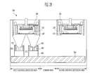
- FIGS. 2A through 2D are views illustrating a method of depositing an organic material according to a first embodiment of the present invention, which is performed by the apparatus for depositing an organic material as illustrated in FIG. 1 .
- the deposition source holding unit 400 holding the organic material deposition source 300 is positioned in the standby area, which is a central area of the chamber 100.
- a robot arm see FIG. 5
- a transfer chamber see FIG. 5
- the organic deposition source 300 keeps evaporating and spraying the organic material, even when being positioned in the standby area. However, when the organic material deposition source 300 is positioned in the standby area, organic material is not being deposited on either of the first or the second substrate 110 or 110'. Therefore, while first or second substrate 110 or 110' is being aligned, the angle limiting plate 410 provided on the upper outer wall of the deposition source holding unit 400 blocks the evaporated organic material from reaching either of the first or second substrate 110 or 110'.
- the angle limiting plate 410 is provided on the upper outer wall of the deposition source holding unit 400 so that a barrier layer provided in earlier deposition apparatuses is no longer necessary.
- the barrier layer is provided in earlier deposition apparatuses and is formed between the substrate and the organic material deposition source to prevent the organic material from being depositing on the substrate while the alignment process of the substrate is being performed.
- the deposition source holding unit 400 positioned in the standby area of the chamber 100 as illustrated in FIG. 2A is transferred to the first substrate deposition area as illustrated in FIG. 2B so that the first substrate 110 faces the organic material deposition source 300 so that the deposition process can be performed on the first substrate 110.
- deposition source 300 moves in the same first direction within the first substrate deposition area during the deposition onto the first substrate 110.
- the second substrate 110' is transferred to the second substrate deposition area of the chamber from an outside and the alignment process of the transferred second substrate 110' is performed by the second substrate aligning unit 210 while the deposition process with respect to the first substrate 110 is carried out. That is, the transfer and the alignment processes of the second substrate 110' are performed simultaneously with the deposition process with respect to the first substrate 110.
- the source holding unit 400 is transferred back into the standby area of the chamber 100 by transfer unit 500 as illustrated in FIG. 2C , and the first substrate 110 is removed from the chamber 100.
- the removal of first substrate 110 is implemented by the robot arm provided in the transfer chamber as described above and as illustrated in FIG. 5 .
- the deposition source holding unit 400 positioned in the standby area of the chamber 100 is transferred to the second substrate deposition area as illustrated in FIG. 2D by the transfer unit 500 and the deposition process is performed within the second substrate deposition area.
- deposition is performed on second substrate 110' while a new third substrate is transferred into the chamber and into the first substrate deposition area and is aligned by the first substrate aligning unit 200.
- deposition source is moved in the same direction (i.e., the first direction) as when moved from ones of the standby area and the first and second substrate deposition areas. As will be described later in the second embodiment of FIGS.
- the deposition source holding unit 400 is transferred again back to the standby area of the chamber 100 by the transfer unit 500 as illustrated in FIG. 2A and the second substrate 110' is removed from the chamber and a new fourth substrate is transferred into the chamber and to the second substrate deposition area.
- the deposition process with respect to the second substrate 110' is performed while the transfer and the alignment processes with respect to the first substrate 110 are performed in the same chamber so that waste of organic material is reduced and throughput can be increased, thereby maximizing material efficiency and minimizing a processing tack time.
- the width of the chamber 100 must be increased in the direction that the deposition process is performed (the first direction).
- the chamber length must be increased about two times in the first direction (horizontal direction) to allow for the deposition with respect to the first and second substrates 110 and 110'.
- the direction that the deposition source moves during a deposition is different from the direction that the deposition source is moved to get from one substrate deposition area to another.
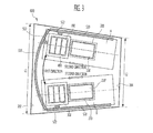
- FIG. 3 is a view illustrating an apparatus for depositing an organic material according to a second embodiment of the present invention.
- the shadow mask and the deposition source are identical to those in the first embodiment of the present invention as illustrated in FIG. 1 , their descriptions will be omitted and same elements are assigned with same reference numerals for illustrative purposes.
- an apparatus for depositing an organic material includes a chamber 600 having an interior divided into a first substrate deposition area A and a second substrate deposition area B, a first substrate aligning unit 200 positioned in the first substrate deposition area A to align a first substrate 110 transferred from the outside, a second substrate aligning unit 210 positioned in the second substrate deposition area B to align a second substrate 110' transferred from the outside, at least one organic material deposition source 300 for spraying particles of the organic material onto the first and second substrates 110 and 110', a deposition source holding unit 400 for holding the organic material deposition source 300, a first transferring unit 510 for rotating the organic material deposition source in a first direction to move the organic material deposition source 300 from one of a first and second substrate deposition area to another of a first and second deposition area, and a second transferring unit 520 for transferring the deposition source holding unit 400 in a second direction within one of the first and second substrate deposition areas.
- a vacuum state is maintained within the chamber 600 by a vacuum pump (not shown).
- the transfer and carrying of the substrate into the chamber 600 are implemented by a robot arm (see FIG. 5 ) provided in a transfer chamber (see FIG. 5 ) connected to the chamber 600 of a cluster type deposition system.
- the first substrate deposition area A and the second substrate deposition are B, as illustrated, are arranged almost in parallel to each other near the second direction, wherein the deposition of the substrates performed in the respective deposition areas A and B is performed by which the deposition source holding unit 400 holding the deposition source 300 is reciprocated in the second direction by the second transferring unit 520.
- the deposition source holding unit 400 When deposition on the first substrate 110 is completed in the first substrate deposition area A, the deposition source holding unit 400 is rotated in the first direction by the first transferring unit 510 so that it is positioned within the second substrate deposition area B, and then the deposition source holding unit 400 is reciprocated in the second direction by the second transferring unit 520 during the deposition on the second substrate 110'.
- the deposition source holding unit 400 is rotated in the first direction by the first transferring unit 510 so that it is positioned within the first substrate deposition area A, and then the deposition source holding unit 400 is reciprocated in the second direction by the second transferring unit 520 during deposition on a newly entered third substrate.
- the first and second transferring units 510 and 520 are preferably implemented so that the use of the first and second transferring units 510 and 520 can be suitable in the chamber 600 maintained in the vacuum state, and that the transfer speed of the organic material deposition source 300 can be controlled depending on processing conditions.
- the first and second transferring units 510 and 520 may include holders 512 and 522 for holding each substrates, a ball screw (not shown), a motor (not shown) for rotating the ball screw, and a guide (not shown) for guiding the deposition source holding unit 400, however, this description is provided only for illustrative purposes.
- the transferring units 510 and 520 may be implemented so that the organic material deposition source 300 can be driven at a constant speed using a linear motor (not shown).
- the width of the chamber must be increased about two times in the first direction that the deposition source moves.
- the direction that the deposition source is transferred to perform the deposition of the respective substrates is different from the direction that the deposition source 300 is transferred to move from one substrate deposition area to the other (first direction), so that the size and shape of chamber 600 of the second embodiment of the present invention is more space efficient than the process chamber 100 of the first embodiment of the present invention.
- the body of the chamber 600 is implemented as a polygonal container having a length L1 on a first side 102 longer than a length L2 on a second side 104 such that the first transferring unit 510 can be rotated in the first direction and accordingly, the increase of the width of the chamber 600 can be minimized.
- the body of the chamber 600 is depicted as a polygonal container in the embodiment as illustrated in FIG. 3 , this is provided only for illustrative purposes.
- the body of the chamber can instead be implemented as a pentagonal container in which the first side 102 is bent.
- the first side 102 is adjacent to the first transferring unit 510 and the second side 104 is opposite to the first side 102, wherein the transfer and the carrying of the substrates into and out of chamber 600 are performed on the second side 104.
- the second side 104 has an opening (not shown) such that the transfer and the carrying of the substrates can be performed.
- a first substrate 110 is transferred into the chamber 600 through an opening (not shown) formed in the second side 104 of the body of the chamber 100. Then, an alignment process is performed by the first substrate aligning unit 200. Then, the deposition source holding unit 400 is reciprocated in the second direction within the first substrate deposition area A by the second transferring unit 520 positioned in the first substrate deposition area A so that the deposition process on the first substrate 110 can be performed.
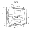
- the second substrate 110' is transferred into the chamber 600 through the opening (not shown) formed in the second side 104 and as illustrated in FIG. 4B , and an alignment process is performed by the second substrate aligning unit 210.
- the first substrate aligning unit 200 and the second substrate aligning unit 210 are respectively positioned in the first substrate deposition area A and the second substrate deposition area B, and since configuration thereof is identical to that as illustrated in FIG. 1 , the description will be omitted. That is, in the embodiment of the present invention, the transfer and the alignment process of the second substrate 110' are performed simultaneously and within the same chamber 600 as the deposition of organic material onto the first substrate 110.
- the deposition source holding unit 400 is rotated in the first direction by the first transferring unit 510 so that it is positioned within the second substrate deposition area B.
- the first substrate 110 upon which the deposition process is completed, is removed from chamber 600 and a new first substrate 110 (hereinafter a third substrate) enters the first substrate deposition area A of the chamber 600 for alignment.
- the deposition source holding unit 400 containing the organic material deposition source 300 is rotated from the first substrate deposition area A to the second substrate deposition area B by the first transferring unit 510 in a first direction that is essentially orthogonal to the second direction, the width of the chamber 600 can be remarkably reduced in comparison to the chamber 100 of the first embodiment of FIGS. 1 through 2D .
- the chamber 600 is implemented as a polygonal container having the length L1 on the first side 102 longer than the length L2 on the second side 104 to enable the deposition source holding unit 400 and the organic material deposition source 300 to be rotated so that spatial use can be maximized.
- the source holding unit 400 After the deposition source holding unit 400 is positioned in the second substrate deposition are B as illustrated in FIG. 4D , the source holding unit 400 reciprocates in the second direction within the second substrate deposition area B so that the deposition process on the second substrate 110' can be performed.
- the alignment process of the third substrate that is newly transferred into the chamber 600 is performed by the first substrate aligning unit 200 positioned in the first substrate deposition area A simultaneous with the deposition process on the second substrate 110' in the second substrate deposition area B being carried out. That is, in the second embodiment of the present invention, the transfer and the alignment processes of the new first substrate 110 (aka third substrate) are performed in the same chamber 600 and at the same time that the deposition process on the second substrate 110' is being performed. When the deposition process on the second substrate 110' is completed, the process sequence as illustrated in FIGS. 4A through 4D are repeated and the deposition and alignment processes of the respective substrates are performed.
- FIG. 5 is a block diagram schematically illustrating an organic material deposition system 10 including an organic material deposition apparatus according to a third embodiment of the present invention.
- the organic material deposition system 10 as illustrated in FIG. 5 is provided with process chambers 600a and 600b analogous in design to process chamber 600 of FIG. 3 .
- the body of chambers 600a and 600b of FIG. 5 include a polygonal container having a first side longer than a second side to maximize the spatial use so that more process chambers can be provided in a limited space environment such as the cluster system 10 of FIG. 5 .
- the system 10 for depositing an organic material is implemented as a cluster type system including a plurality of process chambers 600a, 600b, 700a and 700b for performing the deposition process of an organic material, a transfer chamber 20 for commonly connecting each of process chambers 600a, 600b, 700a and 700b, and load lock chambers 30 and 32 for loading and/or unloading substrates 110, 110', and 110" inserted into the process chambers through the transfer chamber.
- a shadow mask unit 40 may be further provided at a side of the transfer chamber 20 to be used during the deposition process in the process chambers 600a, 600b, 700a and 700b.
- the process chambers 600a, 600b, 700a and 700b are organic material deposition apparatuses where the deposition process of an organic material is performed and include process chambers 600a and 600b that each perform a deposition process on at least two substrates and process chambers 700a and 700b that perform a deposition process on a single substrate. That is, in the third embodiment of FIG. 5 , first and second process chambers 600a and 600b each perform the deposition process of two substrates and are implemented such that the deposition process is performed with respect to one substrate while transfer and alignment processes on the other substrate are being performed. In this case, the first and second process chambers 600a and 600b are implemented as in the second embodiment of the organic material deposition apparatus as described with reference to FIGS. 3 through 4D . The third and fourth process chambers 700a and 700b sequentially perform the alignment and deposition process of a single substrate, respectively.
- the first and second process chambers 600a and 600b are implemented as a polygonal container having first and second sides with different lengths so that space occupied by the first and second process chambers 600a and 600b can be remarkably reduced and the third and fourth process chambers 700a and 700b can be further provided.
- deposition yield is considerably improved over earlier deposition systems.
- the respective process chambers 600a, 600b, 700a and 700b may deposit additional organic materials on the substrate respectively or may deposit a same organic material on the substrate.
- a first organic material is deposited in the first and third process chambers 600a and 700a and a second organic material is deposited in the second and fourth process chambers 600b and 700b.
- the substrate on which the deposition process of the first organic material is completed in the first process chamber 600a is transferred to the second process chamber 600b and then the second organic material is further deposited.
- the substrate on which the deposition of the first organic material is completed in the third process chamber 700a is transferred to the fourth process chamber 700b and the second organic material is further deposited in the fourth process chamber 700b.
- the transfer chamber 20 is connected to the above-mentioned process chambers 600a, 600b, 700a and 700b, the load lock chambers 30 and 32, and the shadow mask unit 40 through side wall regions of the transfer chamber 20.
- penetration portions 24 are provided to allow the substrate to enter and exit in the respective side wall regions.
- the transfer chamber 20 includes a body 22 having a transferring space for substrate transfer and a pair of robot arms 26 and 26' provided in the body 22.
- the pair of robot arms 26 and 26' transfers the substrate provided in the load lock chamber 30 to one of the process chambers 600a, 600b, 700a and 700b or transfers and carries the substrate on which the first deposition is performed by process chamber 600a or 700a to another process chamber 600b or 700b or the load lock chamber 32.
- the load lock chambers 30 and 32 loads and/or unloads the substrates 110, 110', and 110" inserted into the process chamber.
- At least two robot arms 26 and 26' are provided in the body 22 of the transfer chamber 20 so that the second substrate 110' can be transferred to the process chamber 600a or 600b while the deposition process of the first substrate 110 is being carried out.
- first load lock chamber 30 When the loading of the substrates is completed, a door (not shown) of the first load lock chamber 30 is closed and the first load lock chamber 30 is vacuumed. After that, the first robot arm 26 of the transfer chamber 20 transfers the first substrate 110 among the substrates to the first process chamber 600a through the transfer chamber 20.
- processes in the first process chamber 600a and the second process chamber 600b are identical to the deposition process performed by the organic material deposition apparatus of the chamber 600 of FIGS. 3 through 4D , and will be described in brief as follows.
- the first substrate 110 transferred to the first process chamber 600a is aligned in the first process chamber 600a.
- the deposition process on the first substrate 110 is performed. That is, the first organic material is deposited on the first substrate 110.
- the second substrate 110' among the plurality of substrates loaded in the first load lock chamber 30, is transferred by the second robot arm 26' to the first process chamber 600a at the same time that the first organic material is being deposited onto the first substrate 110 in the first process chamber 600a. That is, when the deposition process on the first substrate 100 is being carried out in the first process chamber 600a, the transfer and the alignment processes of the second substrate 110' are performed in the first process chamber 600a. The deposition process on the second substrate 110' is performed after the alignment process is completed.
- the first substrate 110 on which the deposition process is completed, is transferred to the second process chamber 600b by the first robot arm 26. Accordingly, the first substrate 110 is aligned in the second process chamber 600b and the deposition of the second organic material onto the first substrate 110 is carried out upon completion of the alignment process of first substrate 110 in process chamber 600b.
- the second substrate 110' upon which the deposition process is completed in the first process chamber 600a, is transferred by the second robot arm 26' from the first process chamber 600a to the second process chamber 600b during the deposition process of the second organic material onto the first substrate 110 within the second process chamber 600b.
- the transfer and the alignment processes of the second substrate 110' are performed in the second process chamber 600b at the same time that the deposition process of the second organic layer is being carried out on the first substrate 110 within the second process chamber 600b.
- the first and second substrates 110 and 110' are continuously transferred to the second load lock chamber 32 by the robot arm 26 or 26' and are unloaded respectively.
- process chambers 700a and 700b can process third substrate 100". This begins with the first or second robot arm 26 or 26' transferring the third substrate 110" among the substrates loaded in the first load lock chamber 30 to the third process chamber 700a through the transfer chamber 20. After that, the third substrate 110" is aligned in the third process chamber 700a. When the alignment process is completed, the deposition process of the first organic material on the third substrate 110" is carried out. When the deposition process of the third substrate 110" is completed, a robot arm 26 or 26' transfers the third substrate 110" to the fourth process chamber 700b, and the third substrate 110" is aligned within the fourth process chamber 700b.
- a second organic material is deposited onto the third substrate 110". After that, when the deposition processes of the first and second organic materials on the third substrate 110" are completed, the third substrate 110" is transferred to the second load lock chamber 32 and is unloaded by a robot arm 26 or 26'.
- the deposition processes of the third substrate 110 that is, the deposition processes performed in the third and fourth process chambers 700a and 700b, may be performed simultaneously with the deposition processes on the first and second substrates 110 and 110'.
- the deposition processes with respect to three substrates can be performed at the same time so that standby time in the respective process chambers can be reduced and productivity and throughput can be increased and maximized.
Landscapes
- Chemical & Material Sciences (AREA)
- Engineering & Computer Science (AREA)
- Chemical Kinetics & Catalysis (AREA)
- Materials Engineering (AREA)
- Mechanical Engineering (AREA)
- Metallurgy (AREA)
- Organic Chemistry (AREA)
- Manufacturing & Machinery (AREA)
- Physical Vapour Deposition (AREA)
- Electroluminescent Light Sources (AREA)
Abstract
Description
- The present invention relates to an apparatus for depositing an organic material and a depositing method thereof that can perform a deposition process with respect to a second substrate while performing transfer and alignment processes with respect to a first substrate in the same chamber.
- An organic light emitting display device has come into the spotlight as a next generation self-emissive display device because of wide viewing angle, excellent contrast and fast response speed characteristics. An organic light emitting diode included in the organic light emitting display device includes first and second electrodes (anode and cathode electrodes) facing each other and an intermediate layer formed between the electrodes. The intermediate layer may include various layers, e.g., a hole injection layer, a hole transport layer, an emission layer, an electron transport layer, or an electron injection layer. In the organic light emitting diode element, such intermediate layers are organic thin films formed of an organic material.
- Accordingly, there are provided an apparatus for depositing an organic material and a deposition method thereof, wherein a deposition process is performed with respect to a second substrate while transfer and alignment processes are performed with respect to a first substrate in a same chamber, so that loss of an organic material during the transfer and alignment processes can be reduced, thereby maximizing material efficiency and minimizing a processing tack time.
- In addition, there is provided an organic material deposition system having more processing chambers arranged in a same space than that of earlier organic material deposition systems, the processing chambers being arranged in a direction where a deposition source moves for the deposition performance with respect to respective substrates is different from a direction where the deposition moves for the deposition of another substrate, so that the size of a chamber is optimized and space use is maximized.
- According to an aspect of the present invention, there is provided a deposition apparatus that includes a chamber having an interior divided into a first substrate deposition area and a second substrate deposition area, an organic material deposition source transferred to within ones of the first and second substrate deposition areas to spray particles of an organic material onto respective ones of first and second substrates and first transferring unit to rotate the organic material deposition source in a first direction from one of the first and second substrate deposition areas to an other of the first and second substrate deposition areas. The deposition apparatus may also include a second transferring unit to reciprocate the organic material deposition source in a second direction within one of the first and second substrate deposition area. The deposition apparatus may also include a first substrate aligning unit positioned in the first substrate deposition area to align the first substrate transferred from an outside and a second substrate aligning unit positioned in the second substrate deposition area to align the second substrate transferred from the outside.
- The first substrate deposition area and the second substrate deposition area may extend in a second direction that intersects the first direction. The organic material deposition source may be a linear deposition source. A body of the chamber may be a polygonal container having a first side adjacent to the first transferring unit that is longer than a second side opposite the first side. The first and second substrates may enter and exit the chamber through the second side of the chamber.
- According to another aspect of the present invention, there is provided a method of depositing an organic material, which includes transferring a first substrate into a first substrate deposition area of a chamber and performing an alignment process on the first substrate, transferring a deposition source to within the first substrate deposition area to perform a deposition process on the first substrate after completion of the alignment process on the first substrate, transferring a second substrate into a second substrate deposition area of the chamber and performing an alignment process on the transferred second substrate while the deposition process on the first substrate is being performed, transferring the deposition source to the second substrate deposition area by rotating the deposition source in a first direction when the deposition process on the first substrate and the alignment process on the second substrate are completed and transferring the deposition source within the second substrate deposition area to perform the deposition process on the second substrate. The method may also include transferring a third substrate into the first substrate deposition area of the chamber and performing an alignment process with respect to the third substrate while performing the deposition process with respect to the second substrate.
- According to still another aspect of the present invention, there is provided an apparatus, which includes a chamber having an interior divided into a first substrate deposition area, a standby area, and a second substrate deposition area, a first substrate aligning unit positioned in the first substrate deposition area to align a first substrate transferred from an outside, a second substrate aligning unit positioned in the second substrate deposition area to align a second substrate transferred from the outside, at least one organic material deposition source to spray particles of an organic material onto ones of the first and second substrates and a transferring unit to transfer the organic material deposition source in a first direction. The apparatus may also include a deposition source holding unit to hold the organic material deposition source and an angle limiting plate arranged on an upper outer wall of the deposition source holding unit. The first substrate deposition area, the standby area, and the second substrate deposition area may be arranged in a line extending in the first direction.
- According to still another aspect of the present invention, there is provided a method of depositing an organic material, which includes positioning a deposition source in a standby area of a chamber while a first substrate is transferred from an outside into a first substrate deposition area of the chamber and while an alignment process is being performed on the first substrate, performing a deposition process with respect to the first substrate by transferring the deposition source positioned in the standby area of the chamber into the first substrate deposition area after the alignment process with respect to the first substrate is completed, transferring a second substrate from an outside into a second substrate deposition area and performing an alignment process with respect to the second substrate, transferring the deposition source from the first substrate deposition area back to the standby area of the chamber after the deposition process with respect to the first substrate is completed and performing a deposition process with respect to the second substrate by transferring the deposition source positioned in the standby area of the chamber into the second substrate deposition area after the alignment process with respect to the second substrate is completed. The alignment process with respect to the second substrate may be performed while the deposition process is being performed with respect to the first substrate. The method may also include transferring the first substrate from the first substrate deposition area of the chamber to the outside upon completion of the deposition process on the first substrate and transferring a third substrate into the first substrate deposition area of the chamber from the outside.
- According to still another aspect of the present invention, there is provided a deposition system, which includes a plurality of organic material deposition apparatuses, a transfer chamber to commonly connect the plurality of organic material deposition apparatuses and a load lock chamber to load and/or unload substrates inserted into the organic material deposition apparatuses through the transfer chamber, wherein the plurality of organic material deposition apparatuses comprises a first organic material deposition apparatus to perform a deposition process with respect to at least two substrates and to perform transfer and an alignment processes of at least one of the at least two substrates while performing the deposition process with respect to an other of the at least two substrates. The plurality of organic material deposition apparatuses may further include a second organic material deposition apparatus to sequentially perform a transfer process, an alignment process, and a deposition process with respect to a single substrate.
- The first organic material deposition apparatus may include a chamber having an interior divided into a first substrate deposition area and a second substrate deposition area, an organic material deposition source transferred to within ones of the first and second substrate deposition areas to spray particles of an organic material onto respective ones of first and second substrates and a transferring unit to rotate the organic material deposition source in a first direction from one of the first and second substrate deposition areas to an other of the first and second substrate deposition areas. The chamber may be a polygonal container having a first side adjacent to the first transferring unit that is longer than a second side opposite the first side. The first and second substrates may enter and exit the chamber through the second side of the chamber.
- A more complete appreciation of the invention and many of the attendant advantages thereof, will be readily apparent as the same becomes better understood by reference to the following detailed description when considered in conjunction with the accompanying drawings in which like reference symbols indicate the same or similar components, wherein:
-
FIG. 1 is a cross-sectional view schematically illustrating the configuration of an apparatus for depositing an organic material according to a first embodiment of the present invention; -
FIGS. 2A to 2D are views illustrating a method of depositing an organic material according to the first embodiment of the present invention using the apparatus ofFIG. 1 ; -
FIG. 3 is a view illustrating an apparatus for depositing an organic material according to a second embodiment of the present invention; -
FIGS. 4A to 4D are views illustrating a method of depositing an organic material according to the second embodiment of the present invention using the apparatus ofFIG. 3 ; and -
FIG. 5 is a block diagram schematically of an organic material deposition system according to a third embodiment of the present invention that includes an organic material deposition apparatus according to the second embodiment of the present invention. - In the following detailed description, only certain exemplary embodiments of the present invention have been shown and described, simply by way of illustration. As those skilled in the art would realize, the described embodiments may be modified in various different ways, all without departing from the scope of the present invention. Accordingly, the drawings and description are to be regarded as illustrative in nature and not restrictive. In addition, when an element is referred to as being "on" another element, it can be directly on the another element or be indirectly on the another element with one or more intervening elements interposed therebetween. Also, when an element is referred to as being "connected to" another element, it can be directly connected to the another element or be indirectly connected to the another element with one or more intervening elements interposed therebetween. Hereinafter, like reference numerals refer to like elements.
- An organic light emitting diode included in the organic light emitting display device includes first and second electrodes (anode and cathode electrodes) facing each other and an intermediate layer arranged between the electrodes. The intermediate layer may include various layers, e.g., a hole injection layer, a hole transport layer, an emission layer, an electron transport layer, and/or an electron injection layer. In the organic light emitting diode element, such intermediate layers are organic thin films made out of an organic material.
- In the process of manufacturing an organic light emitting diode element having the aforementioned configuration, organic thin films and electrodes including a hole injection layer, a hole transport layer, an emission layer, an electron transport layer, an electron injection layer and the like may be formed on a substrate through a deposition method using a deposition apparatus.
- In the deposition method, after loading a substrate into a vacuum chamber, a thin film is formed by heating a container containing an organic material to be deposited and then evaporating or sublimating the organic material in the container. An organic thin film is deposited on the substrate by aligning a shadow mask pattern having an opening with a desired shape in front of the substrate and then evaporating or sublimating the organic material.
- Before such a deposition process is performed, a process of transferring a substrate into a chamber, a process of precisely aligning a shadow mask to the substrate, and the like are necessarily performed. According to earlier deposition apparatus and method, the deposition process is impossible during the substrate transfer and mask alignment processes. Further, the substrate transfer and mask alignment processes are separated from the deposition process. Therefore, a processing tack time may be increased.
- In addition, according to earlier deposition apparatus and method, the organic material is continuously evaporated or sublimated from a deposition source during the substrate transfer and mask alignment processes. Therefore, the organic material may be wasted.
- Turning now to
FIG. 1, FIG. 1 is a cross-sectional view schematically illustrating the configuration of an apparatus for depositing an organic material according to a first embodiment of the present invention. Referring toFIG. 1 , the apparatus for depositing an organic material according to the first embodiment of the present invention includes achamber 100 having an interior divided into a first substrate deposition area, a standby area and a second substrate deposition area, a firstsubstrate aligning unit 200 positioned in the first substrate deposition area to align afirst substrate 110 transferred from the outside, a secondsubstrate aligning unit 210 positioned in the second substrate deposition area to align a second substrate 110' transferred from the outside, at least one organicmaterial deposition source 300 for spraying particles of the deposition material onto the first andsecond substrates 110 and 110', a depositionsource holding unit 400 for holding the organicmaterial deposition source 300, and a transferringunit 500 for transferring the deposition source holding unit in a first direction (for example, a horizontal direction). As illustrated inFIG. 1 , the first substrate deposition area, the standby area, and the second substrate deposition area are arranged in a line in the first direction. - Here, a vacuum state is maintained within the
chamber 100 by a vacuum pump (not shown). Two organicmaterial deposition sources 300 are held in the depositionsource holding unit 400 in the first embodiment ofFIG. 1 , and anangle limiting plate 410 is formed on the upper outer wall of the depositionsource holding unit 400. Accordingly, theangle limiting plate 410 functions to limit the spraying direction of the organic material sprayed from the organicmaterial deposition source 300. - The transferring
unit 500 functions to transfer the depositionsource holding unit 400 in the first direction (in a horizontal direction). The transferringunit 500 controls the depositionsource holding unit 400 to be initially positioned in the standby area of thechamber 100. Then, when the alignment of thefirst substrate 110 is completed by the firstsubstrate aligning unit 200, the transferringunit 500 transfers the depositionsource holding unit 400 to the first substrate deposition area to perform a deposition process on thefirst substrate 110. - Thereafter, when the alignment of the second substrate 110' is completed by the second
substrate aligning unit 210, the transferringunit 500 transfers the depositionsource holding unit 400 to the second substrate deposition area to perform a deposition process on the second substrate 110'. - That is, transfer and alignment processes are performed with respect to the second substrate 110' while a deposition process is being performed with respect to the
first substrate 110. Conversely, transfer and alignment processes are performed with respect to thefirst substrate 110 while a deposition process is being performed with respect to the second substrate 110'. Accordingly, a processing tack time can be considerably reduced and the amount of waste of organic material is also reduced, so that material efficiency can be maximized. - The transferring
unit 500 is preferably implemented so that the use of the transferringunit 500 can be suitable in thechamber 100 maintained in the vacuum state, and that the transfer speed of the organicmaterial deposition source 300 can be controlled depending on processing conditions. The transferringunit 500 may include a ball screw (not shown), a motor (not shown) for rotating the ball screw, and a guide (not shown) for guiding the depositionsource holding unit 400, however this description is provided only for illustrative purposes. In another embodiment, the transferringunit 500 may be implemented so that the organicmaterial deposition source 300 can be driven at a constant speed using a linear motor (not shown). - In addition, a
mask pattern 120 for determining the shape of the organic material to be deposited is positioned at the front sides of the first andsecond substrates 110 and 110', i.e., between the organicmaterial deposition source 300 and the first andsecond substrates 110 and 110'. Accordingly, the organic material evaporated from the organicmaterial deposition source 300 is deposited onto the first andsecond substrates 110 and 110' while passing through themask pattern 120, so that an organic film with a predetermined shape is formed on the first andsecond substrates 110 and 110'. - Meanwhile, the organic
material deposition source 300 contains within an organic material to be deposited on the first andsecond substrates 110 and 110' and heats the received organic material to evaporate the organic material. Then, the organicmaterial deposition source 300 sprays the evaporated organic material onto the first andsecond substrates 110 and 110' so that an organic film is formed on the first andsecond substrates 100 and 110'. The organicmaterial deposition source 300 may be implemented as a linear deposition source or a point deposition source. - It is to be appreciated that it is difficult for the point deposition source to perform the depositions of the organic material on a large area. For the deposition of the organic material on the large area, several point deposition sources must be arranged. When many point sources are used, it is difficult to control the plurality of point deposition sources. Accordingly, in the embodiment of the present invention, the
organic deposition source 300 is preferably implemented as a linear deposition source. - Turning now to
FIGS. 2A through 2D, FIGS. 2A through 2D are views illustrating a method of depositing an organic material according to a first embodiment of the present invention, which is performed by the apparatus for depositing an organic material as illustrated inFIG. 1 . As illustrated inFIG. 2A , after thefirst substrate 110 is transferred into thechamber 100 and before the alignment process is completed on thefirst substrate 110, the depositionsource holding unit 400 holding the organicmaterial deposition source 300 is positioned in the standby area, which is a central area of thechamber 100. To transfer a substrate into thechamber 100, a robot arm (seeFIG. 5 ) and a transfer chamber (seeFIG. 5 ) are connected to thechamber 100 of a cluster type deposition. - The
organic deposition source 300 keeps evaporating and spraying the organic material, even when being positioned in the standby area. However, when the organicmaterial deposition source 300 is positioned in the standby area, organic material is not being deposited on either of the first or thesecond substrate 110 or 110'. Therefore, while first orsecond substrate 110 or 110' is being aligned, theangle limiting plate 410 provided on the upper outer wall of the depositionsource holding unit 400 blocks the evaporated organic material from reaching either of the first orsecond substrate 110 or 110'. - That is, in the embodiment of the present invention, the
angle limiting plate 410 is provided on the upper outer wall of the depositionsource holding unit 400 so that a barrier layer provided in earlier deposition apparatuses is no longer necessary. The barrier layer is provided in earlier deposition apparatuses and is formed between the substrate and the organic material deposition source to prevent the organic material from being depositing on the substrate while the alignment process of the substrate is being performed. - When the alignment on the
first substrate 110 is completed by the firstsubstrate aligning unit 200, the depositionsource holding unit 400 positioned in the standby area of thechamber 100 as illustrated inFIG. 2A is transferred to the first substrate deposition area as illustrated inFIG. 2B so that thefirst substrate 110 faces the organicmaterial deposition source 300 so that the deposition process can be performed on thefirst substrate 110. As illustrated inFIG. 2B , in the first embodiment,deposition source 300 moves in the same first direction within the first substrate deposition area during the deposition onto thefirst substrate 110. - However, in the embodiment of the present invention, the second substrate 110' is transferred to the second substrate deposition area of the chamber from an outside and the alignment process of the transferred second substrate 110' is performed by the second
substrate aligning unit 210 while the deposition process with respect to thefirst substrate 110 is carried out. That is, the transfer and the alignment processes of the second substrate 110' are performed simultaneously with the deposition process with respect to thefirst substrate 110. - Next, when the deposition process with respect to the
first substrate 110 is completed, thesource holding unit 400 is transferred back into the standby area of thechamber 100 bytransfer unit 500 as illustrated inFIG. 2C , and thefirst substrate 110 is removed from thechamber 100. The removal offirst substrate 110 is implemented by the robot arm provided in the transfer chamber as described above and as illustrated inFIG. 5 . - When the alignment with respect to the second substrate 110' is completed, the deposition
source holding unit 400 positioned in the standby area of thechamber 100 is transferred to the second substrate deposition area as illustrated inFIG. 2D by thetransfer unit 500 and the deposition process is performed within the second substrate deposition area. In this embodiment, deposition is performed on second substrate 110' while a new third substrate is transferred into the chamber and into the first substrate deposition area and is aligned by the firstsubstrate aligning unit 200. While organic material is being deposited onto second substrate 110', deposition source is moved in the same direction (i.e., the first direction) as when moved from ones of the standby area and the first and second substrate deposition areas. As will be described later in the second embodiment ofFIGS. 3 through 4D , this is not the most efficient use of space as thechamber 100 according to the first embodiment must be designed to extend an extra large distance in the first direction when the direction of translation of the deposition source in between depositions is the same as direction of movement of thedeposition source 300 during a deposition. - When the deposition process with respect to the second substrate 110' is completed, the deposition
source holding unit 400 is transferred again back to the standby area of thechamber 100 by thetransfer unit 500 as illustrated inFIG. 2A and the second substrate 110' is removed from the chamber and a new fourth substrate is transferred into the chamber and to the second substrate deposition area. According to the method in accordance with the first embodiment of the present invention, the deposition process with respect to the second substrate 110' is performed while the transfer and the alignment processes with respect to thefirst substrate 110 are performed in the same chamber so that waste of organic material is reduced and throughput can be increased, thereby maximizing material efficiency and minimizing a processing tack time. - However, in the first embodiment of the present invention as illustrated in
FIGS. 1 through 2D , since the direction that thedeposition source 300 moves during a deposition process is the same as the direction that thedeposition source 300 moves when going from the first substrate deposition area to the second substrate deposition area (or from the second substrate deposition area to the first substrate deposition area) to perform the deposition with respect to another substrate, the width of thechamber 100 must be increased in the direction that the deposition process is performed (the first direction). - That is, since the
deposition source 300 is transferred in the same first direction (horizontal direction) as the deposition performance direction when thedeposition source 300 is transferred to perform the deposition on the second substrate 110' after the deposition with respect to thefirst substrate 110 is completed, the chamber length must be increased about two times in the first direction (horizontal direction) to allow for the deposition with respect to the first andsecond substrates 110 and 110'. - Therefore, in the second embodiment of the present invention, the direction that the deposition source moves during a deposition is different from the direction that the deposition source is moved to get from one substrate deposition area to another. By designing the chamber as such according to the second embodiment of the present invention, the size and shape of the chamber results in optimum space efficiency and the above-mentioned problem will be solved.
- Turning now to
FIG. 3, FIG. 3 is a view illustrating an apparatus for depositing an organic material according to a second embodiment of the present invention. However, since the shadow mask and the deposition source are identical to those in the first embodiment of the present invention as illustrated inFIG. 1 , their descriptions will be omitted and same elements are assigned with same reference numerals for illustrative purposes. - Referring to
FIG. 3 , an apparatus for depositing an organic material according to the second embodiment of the present invention includes achamber 600 having an interior divided into a first substrate deposition area A and a second substrate deposition area B, a firstsubstrate aligning unit 200 positioned in the first substrate deposition area A to align afirst substrate 110 transferred from the outside, a secondsubstrate aligning unit 210 positioned in the second substrate deposition area B to align a second substrate 110' transferred from the outside, at least one organicmaterial deposition source 300 for spraying particles of the organic material onto the first andsecond substrates 110 and 110', a depositionsource holding unit 400 for holding the organicmaterial deposition source 300, afirst transferring unit 510 for rotating the organic material deposition source in a first direction to move the organicmaterial deposition source 300 from one of a first and second substrate deposition area to another of a first and second deposition area, and asecond transferring unit 520 for transferring the depositionsource holding unit 400 in a second direction within one of the first and second substrate deposition areas. - Here, a vacuum state is maintained within the
chamber 600 by a vacuum pump (not shown). The transfer and carrying of the substrate into thechamber 600 are implemented by a robot arm (seeFIG. 5 ) provided in a transfer chamber (seeFIG. 5 ) connected to thechamber 600 of a cluster type deposition system. - The first substrate deposition area A and the second substrate deposition are B, as illustrated, are arranged almost in parallel to each other near the second direction, wherein the deposition of the substrates performed in the respective deposition areas A and B is performed by which the deposition
source holding unit 400 holding thedeposition source 300 is reciprocated in the second direction by thesecond transferring unit 520. - When deposition on the
first substrate 110 is completed in the first substrate deposition area A, the depositionsource holding unit 400 is rotated in the first direction by thefirst transferring unit 510 so that it is positioned within the second substrate deposition area B, and then the depositionsource holding unit 400 is reciprocated in the second direction by thesecond transferring unit 520 during the deposition on the second substrate 110'. - Similarly, when the deposition of the second substrate 110' is completed in the second substrate deposition area B, the deposition
source holding unit 400 is rotated in the first direction by thefirst transferring unit 510 so that it is positioned within the first substrate deposition area A, and then the depositionsource holding unit 400 is reciprocated in the second direction by thesecond transferring unit 520 during deposition on a newly entered third substrate. - The first and second transferring
units units chamber 600 maintained in the vacuum state, and that the transfer speed of the organicmaterial deposition source 300 can be controlled depending on processing conditions. The first and second transferringunits holders source holding unit 400, however, this description is provided only for illustrative purposes. In another variation, the transferringunits material deposition source 300 can be driven at a constant speed using a linear motor (not shown). - In the first embodiment described with reference to
FIGS. 1 through 2D , since the deposition source is transferred to perform the deposition of the respective substrates in the chamber in the same direction (horizontal direction) as the direction the deposition source is transferred when being moved from one substrate deposition area to the other, the width of the chamber must be increased about two times in the first direction that the deposition source moves. However, in the embodiment as illustrated inFIG. 3 , the direction that the deposition source is transferred to perform the deposition of the respective substrates (second direction) is different from the direction that thedeposition source 300 is transferred to move from one substrate deposition area to the other (first direction), so that the size and shape ofchamber 600 of the second embodiment of the present invention is more space efficient than theprocess chamber 100 of the first embodiment of the present invention. - However, to this end, in the embodiment as illustrated in
FIG. 3 , the body of thechamber 600 is implemented as a polygonal container having a length L1 on afirst side 102 longer than a length L2 on asecond side 104 such that thefirst transferring unit 510 can be rotated in the first direction and accordingly, the increase of the width of thechamber 600 can be minimized. Although the body of thechamber 600 is depicted as a polygonal container in the embodiment as illustrated inFIG. 3 , this is provided only for illustrative purposes. The body of the chamber can instead be implemented as a pentagonal container in which thefirst side 102 is bent. - In this case, the
first side 102 is adjacent to thefirst transferring unit 510 and thesecond side 104 is opposite to thefirst side 102, wherein the transfer and the carrying of the substrates into and out ofchamber 600 are performed on thesecond side 104. As a result, thesecond side 104 has an opening (not shown) such that the transfer and the carrying of the substrates can be performed. - Hereinafter, the method of depositing an organic material performed by the apparatus illustrated in
FIG. 3 will be described in detail with reference toFIGS. 4A to 4D . Referring toFIG. 4A , afirst substrate 110 is transferred into thechamber 600 through an opening (not shown) formed in thesecond side 104 of the body of thechamber 100. Then, an alignment process is performed by the firstsubstrate aligning unit 200. Then, the depositionsource holding unit 400 is reciprocated in the second direction within the first substrate deposition area A by thesecond transferring unit 520 positioned in the first substrate deposition area A so that the deposition process on thefirst substrate 110 can be performed. - During the deposition process with respect to the
first substrate 110, the second substrate 110' is transferred into thechamber 600 through the opening (not shown) formed in thesecond side 104 and as illustrated inFIG. 4B , and an alignment process is performed by the secondsubstrate aligning unit 210. - At this time, the first
substrate aligning unit 200 and the secondsubstrate aligning unit 210 are respectively positioned in the first substrate deposition area A and the second substrate deposition area B, and since configuration thereof is identical to that as illustrated inFIG. 1 , the description will be omitted. That is, in the embodiment of the present invention, the transfer and the alignment process of the second substrate 110' are performed simultaneously and within thesame chamber 600 as the deposition of organic material onto thefirst substrate 110. - When the deposition process on the
first substrate 110 and the alignment process on the second substrate 110' are completed, the depositionsource holding unit 400, as illustrated inFIG. 4C , is rotated in the first direction by thefirst transferring unit 510 so that it is positioned within the second substrate deposition area B. At this time, thefirst substrate 110, upon which the deposition process is completed, is removed fromchamber 600 and a new first substrate 110 (hereinafter a third substrate) enters the first substrate deposition area A of thechamber 600 for alignment. Because the depositionsource holding unit 400 containing the organicmaterial deposition source 300 is rotated from the first substrate deposition area A to the second substrate deposition area B by thefirst transferring unit 510 in a first direction that is essentially orthogonal to the second direction, the width of thechamber 600 can be remarkably reduced in comparison to thechamber 100 of the first embodiment ofFIGS. 1 through 2D . - That is, as illustrated in
FIGS. 3 through 4D , in the second embodiment of the present invention, thechamber 600 is implemented as a polygonal container having the length L1 on thefirst side 102 longer than the length L2 on thesecond side 104 to enable the depositionsource holding unit 400 and the organicmaterial deposition source 300 to be rotated so that spatial use can be maximized. - After the deposition
source holding unit 400 is positioned in the second substrate deposition are B as illustrated inFIG. 4D , thesource holding unit 400 reciprocates in the second direction within the second substrate deposition area B so that the deposition process on the second substrate 110' can be performed. - In addition, the alignment process of the third substrate that is newly transferred into the
chamber 600 is performed by the firstsubstrate aligning unit 200 positioned in the first substrate deposition area A simultaneous with the deposition process on the second substrate 110' in the second substrate deposition area B being carried out. That is, in the second embodiment of the present invention, the transfer and the alignment processes of the new first substrate 110 (aka third substrate) are performed in thesame chamber 600 and at the same time that the deposition process on the second substrate 110' is being performed. When the deposition process on the second substrate 110' is completed, the process sequence as illustrated inFIGS. 4A through 4D are repeated and the deposition and alignment processes of the respective substrates are performed. - Turning now to
FIG. 5, FIG. 5 is a block diagram schematically illustrating an organicmaterial deposition system 10 including an organic material deposition apparatus according to a third embodiment of the present invention. The organicmaterial deposition system 10 as illustrated inFIG. 5 is provided withprocess chambers chamber 600 ofFIG. 3 . Specifically, the body ofchambers FIG. 5 include a polygonal container having a first side longer than a second side to maximize the spatial use so that more process chambers can be provided in a limited space environment such as thecluster system 10 ofFIG. 5 . - Referring to
FIG. 5 , thesystem 10 for depositing an organic material according to the third embodiment of the present invention is implemented as a cluster type system including a plurality ofprocess chambers transfer chamber 20 for commonly connecting each ofprocess chambers lock chambers substrates shadow mask unit 40 may be further provided at a side of thetransfer chamber 20 to be used during the deposition process in theprocess chambers - The
process chambers process chambers process chambers FIG. 5 , first andsecond process chambers second process chambers FIGS. 3 through 4D . The third andfourth process chambers - In the cluster type deposition system according to the third embodiment of the present invention, the first and
second process chambers second process chambers fourth process chambers - The
respective process chambers FIG. 5 , a first organic material is deposited in the first andthird process chambers fourth process chambers - The substrate on which the deposition process of the first organic material is completed in the
first process chamber 600a is transferred to thesecond process chamber 600b and then the second organic material is further deposited. Similarly, the substrate on which the deposition of the first organic material is completed in thethird process chamber 700a is transferred to thefourth process chamber 700b and the second organic material is further deposited in thefourth process chamber 700b. - The
transfer chamber 20 is connected to the above-mentionedprocess chambers load lock chambers shadow mask unit 40 through side wall regions of thetransfer chamber 20. In this case,penetration portions 24 are provided to allow the substrate to enter and exit in the respective side wall regions. - That is, the
transfer chamber 20 includes abody 22 having a transferring space for substrate transfer and a pair ofrobot arms 26 and 26' provided in thebody 22. The pair ofrobot arms 26 and 26' transfers the substrate provided in theload lock chamber 30 to one of theprocess chambers process chamber process chamber load lock chamber 32. Theload lock chambers substrates - In the third embodiment of the present invention, at least two
robot arms 26 and 26' are provided in thebody 22 of thetransfer chamber 20 so that the second substrate 110' can be transferred to theprocess chamber first substrate 110 is being carried out. - Operation of the organic
material deposition system 10 according to the third embodiment of the present invention will be described in brief as follows. First, when a plurality of substrates are transferred from an external carrier apparatus (not shown) to the firstload lock chamber 30, the firstload lock chamber 30 loads the transferred substrates. - When the loading of the substrates is completed, a door (not shown) of the first
load lock chamber 30 is closed and the firstload lock chamber 30 is vacuumed. After that, thefirst robot arm 26 of thetransfer chamber 20 transfers thefirst substrate 110 among the substrates to thefirst process chamber 600a through thetransfer chamber 20. In this case, processes in thefirst process chamber 600a and thesecond process chamber 600b are identical to the deposition process performed by the organic material deposition apparatus of thechamber 600 ofFIGS. 3 through 4D , and will be described in brief as follows. - The
first substrate 110 transferred to thefirst process chamber 600a is aligned in thefirst process chamber 600a. When the alignment process is completed, the deposition process on thefirst substrate 110 is performed. That is, the first organic material is deposited on thefirst substrate 110. - The second substrate 110', among the plurality of substrates loaded in the first
load lock chamber 30, is transferred by the second robot arm 26' to thefirst process chamber 600a at the same time that the first organic material is being deposited onto thefirst substrate 110 in thefirst process chamber 600a. That is, when the deposition process on thefirst substrate 100 is being carried out in thefirst process chamber 600a, the transfer and the alignment processes of the second substrate 110' are performed in thefirst process chamber 600a. The deposition process on the second substrate 110' is performed after the alignment process is completed. - The
first substrate 110, on which the deposition process is completed, is transferred to thesecond process chamber 600b by thefirst robot arm 26. Accordingly, thefirst substrate 110 is aligned in thesecond process chamber 600b and the deposition of the second organic material onto thefirst substrate 110 is carried out upon completion of the alignment process offirst substrate 110 inprocess chamber 600b. - After the
first substrate 110 enters thesecond process chamber 600b, the second substrate 110', upon which the deposition process is completed in thefirst process chamber 600a, is transferred by the second robot arm 26' from thefirst process chamber 600a to thesecond process chamber 600b during the deposition process of the second organic material onto thefirst substrate 110 within thesecond process chamber 600b. - That is, the transfer and the alignment processes of the second substrate 110' are performed in the
second process chamber 600b at the same time that the deposition process of the second organic layer is being carried out on thefirst substrate 110 within thesecond process chamber 600b. - By doing so, when the deposition processes of the first and second organic materials on the first and
second substrates 110 and 110' are completed, the first andsecond substrates 110 and 110' are continuously transferred to the secondload lock chamber 32 by therobot arm 26 or 26' and are unloaded respectively. - While the first and
second substrates 110 and 110' are being processed inprocess chambers process chambers third substrate 100". This begins with the first orsecond robot arm 26 or 26' transferring thethird substrate 110" among the substrates loaded in the firstload lock chamber 30 to thethird process chamber 700a through thetransfer chamber 20. After that, thethird substrate 110" is aligned in thethird process chamber 700a. When the alignment process is completed, the deposition process of the first organic material on thethird substrate 110" is carried out. When the deposition process of thethird substrate 110" is completed, arobot arm 26 or 26' transfers thethird substrate 110" to thefourth process chamber 700b, and thethird substrate 110" is aligned within thefourth process chamber 700b. When the alignment process is completed, a second organic material is deposited onto thethird substrate 110". After that, when the deposition processes of the first and second organic materials on thethird substrate 110" are completed, thethird substrate 110" is transferred to the secondload lock chamber 32 and is unloaded by arobot arm 26 or 26'. - At this time, the deposition processes of the
third substrate 110", that is, the deposition processes performed in the third andfourth process chambers second substrates 110 and 110'. - Consequently, according to the organic
material deposition system 10 in accordance with the third embodiment of the present invention, the deposition processes with respect to three substrates can be performed at the same time so that standby time in the respective process chambers can be reduced and productivity and throughput can be increased and maximized. - While the present invention has been described in connection with certain exemplary embodiments, it is to be understood that the invention is not limited to the disclosed embodiments, but, on the contrary, is intended to cover various modifications and equivalent arrangements included within the scope of the appended claims.
Claims (15)
- A deposition apparatus, comprising:a chamber (100, 600, 600a, 600b) having an interior divided into a first substrate deposition area and a second substrate deposition area;an organic material deposition source (300) moveable between the first and second substrate deposition areas to spray particles of an organic material onto respective ones of first and second substrates (110, 110'); anda transferring unit (500, 510) for moving the organic material deposition source (300) from one of the first and second substrate deposition areas to the other of the first and second substrate deposition areas.
- The apparatus of claim 1, wherein the transferring unit comprises a first transferring unit (510) arranged to rotate the organic material deposition source (300) in a first direction between the first and second substrate deposition areas, the apparatus further comprising a second transferring unit (520) to reciprocate the organic material deposition source in a second direction within one of the first and second substrate deposition areas.
- The apparatus of claim 1 or 2, further comprising:a first substrate aligning unit (200) positioned in the first substrate deposition area to align the first substrate; anda second substrate aligning unit (210) positioned in the second substrate deposition area to align the second substrate.
- The apparatus of any one of the preceding claims, wherein the organic material deposition source is a linear deposition source.
- The apparatus of any one of the preceding claims, wherein a body of the chamber is a polygonal container having a first side (102) that is longer than a second side (104) opposite the first side.
- The apparatus of claim 5, wherein the first and second substrates are arranged to enter and exit the chamber through the second side (104) of the chamber.
- The apparatus of any one of the preceding claims, further comprising:a deposition source holding unit (400) to hold the organic material deposition source; andan angle limiting plate (410) arranged to limit the deposition angle of the organic material deposition source.
- A method of depositing an organic material onto a substrate, comprising:transferring a first substrate into a first substrate deposition area of a chamber;transferring a deposition source to within the first substrate deposition area to perform a deposition process on the first substrate;transferring a second substrate into a second substrate deposition area of the chamber while the deposition process on the first substrate is being performed;transferring the deposition source to the second substrate deposition area when the deposition process on the first substrate is complete, to perform the deposition process on the second substrate.
- The method of claim 8, comprising:performing a first alignment process on the first substrate after transferring the first substrate into the first substrate deposition area;transferring the deposition source to within the first substrate deposition area after completing the first alignment process; andperforming a second alignment process on the second substrate while the deposition process on the first substrate is being performed.
- The method of claim 9, wherein the step of transferring the deposition source to the second substrate deposition area comprises rotating the deposition source in a first direction when the deposition process on the first substrate and the alignment process on the second substrate are complete.
- The method of claim 8, 9 or 10, further comprising:positioning the deposition source in a standby area of a chamber while a first substrate is transferred from an outside into the first substrate deposition area of the chamber and while an alignment process is being performed on the first substrate;performing a deposition process with respect to the first substrate by transferring the deposition source positioned in the standby area of the chamber into the first substrate deposition area after the alignment process with respect to the first substrate is completed;transferring the deposition source from the first substrate deposition area back to the standby area of the chamber after the deposition process with respect to the first substrate is completed; andperforming a deposition process with respect to the second substrate by transferring the deposition source positioned in the standby area of the chamber into the second substrate deposition area after the alignment process with respect to the second substrate is completed.
- The method of any one of claims 8 to 11, further comprising transferring a third substrate into the first substrate deposition area of the chamber and performing an alignment process with respect to the third substrate while performing the deposition process with respect to the second substrate.
- The method of claim 12, wherein the alignment process with respect to the second substrate is performed while the deposition process is being performed with respect to the first substrate.
- A deposition system, comprising:a plurality of deposition apparatuses according to any one of claims 1 to 7;a transfer chamber (20) to commonly connect the plurality of deposition apparatuses; anda load lock chamber (30, 32) to load and/or unload substrates inserted into the deposition apparatuses through the transfer chamber.
- The system of claim 14, further comprising apparatus (700a, 700b) to sequentially perform a transfer process, an alignment process, and a deposition process with respect to a single substrate.
Applications Claiming Priority (2)
| Application Number | Priority Date | Filing Date | Title |
|---|---|---|---|
| KR20090038907 | 2009-05-04 | ||
| KR1020100010837A KR101152578B1 (en) | 2009-05-04 | 2010-02-05 | Apparatus for depositing Organic material and organic material depositing system using the same and depositing method thereof |
Publications (2)
| Publication Number | Publication Date |
|---|---|
| EP2248595A1 true EP2248595A1 (en) | 2010-11-10 |
| EP2248595B1 EP2248595B1 (en) | 2013-12-11 |
Family
ID=42315790
Family Applications (1)
| Application Number | Title | Priority Date | Filing Date |
|---|---|---|---|
| EP10161882.5A Active EP2248595B1 (en) | 2009-05-04 | 2010-05-04 | Apparatus for depositing organic material and depositing method thereof |
Country Status (3)
| Country | Link |
|---|---|
| US (2) | US20100279021A1 (en) |
| EP (1) | EP2248595B1 (en) |
| CN (1) | CN101880865B (en) |
Cited By (2)
| Publication number | Priority date | Publication date | Assignee | Title |
|---|---|---|---|---|
| WO2015086049A1 (en) * | 2013-12-10 | 2015-06-18 | Applied Materials, Inc. | Evaporation source for organic material, apparatus having an evaporation source for organic material, system having an evaporation deposition apparatus with an evaporation source for organic materials, and method for operating an evaporation source for organic material |
| WO2019170252A1 (en) * | 2018-03-09 | 2019-09-12 | Applied Materials, Inc. | Vacuum processing system and method of operating a vacuum processing system |
Families Citing this family (20)
| Publication number | Priority date | Publication date | Assignee | Title |
|---|---|---|---|---|
| JP2013112854A (en) * | 2011-11-29 | 2013-06-10 | Canon Inc | Film deposition apparatus and film deposition method |
| KR20130095063A (en) * | 2012-02-17 | 2013-08-27 | 삼성디스플레이 주식회사 | Apparatus for deposition a organic layer and the method for manufacturing of organic light emitting display apparatus using the same |
| KR101346071B1 (en) * | 2012-03-27 | 2013-12-31 | 에스엔유 프리시젼 주식회사 | organic matter evaporation system |
| KR20140006499A (en) * | 2012-07-05 | 2014-01-16 | 삼성디스플레이 주식회사 | Evaporation apparatus |
| CN104756276B (en) * | 2012-08-06 | 2017-03-29 | 铣益系统有限责任公司 | Organic matter deposition device and organic matter deposition method using the device |
| US20140261168A1 (en) * | 2013-03-14 | 2014-09-18 | Applied Materials, Inc. | Multiple chamber module and platform in semiconductor process equipment |
| KR102069189B1 (en) * | 2013-06-17 | 2020-01-23 | 삼성디스플레이 주식회사 | Apparatus for organic layer deposition, and method for manufacturing of organic light emitting display apparatus using the same |
| KR101609185B1 (en) * | 2013-12-13 | 2016-04-05 | 주식회사 선익시스템 | Unit for transferring deposition source, apparatus of deposition having the same and method of deposition |
| CN103789732A (en) * | 2014-02-13 | 2014-05-14 | 上海和辉光电有限公司 | Evaporator and evaporation method |
| KR20160087953A (en) * | 2015-01-14 | 2016-07-25 | 에스엔유 프리시젼 주식회사 | Cluster type evaporation device for manufacturing of OLED |
| KR102426712B1 (en) | 2015-02-16 | 2022-07-29 | 삼성디스플레이 주식회사 | Apparatus and method of manufacturing display apparatus |
| KR102315185B1 (en) * | 2015-02-25 | 2021-10-20 | 삼성디스플레이 주식회사 | Apparatus and mehtod for measuring a deposition rate |
| KR102391346B1 (en) * | 2015-08-04 | 2022-04-28 | 삼성디스플레이 주식회사 | Organic light display apparatus, apparatus for organic layer deposition, and method for manufacturing of organic light emitting display apparatus using the same |
| KR20180007387A (en) * | 2016-07-12 | 2018-01-23 | 삼성디스플레이 주식회사 | Thin film deposition apparatus |
| CN106098600B (en) * | 2016-08-23 | 2019-06-28 | 沈阳拓荆科技有限公司 | Composite film packaging equipment |
| JP2019510129A (en) * | 2017-02-03 | 2019-04-11 | アプライド マテリアルズ インコーポレイテッドApplied Materials,Incorporated | Apparatus and method for continuous evaporation with adjacent substrates |
| KR102380159B1 (en) * | 2017-03-02 | 2022-03-29 | 삼성디스플레이 주식회사 | Deposition equipment, manufacturing method of dislay device, and dislay device manufactured by the method |
| KR102641512B1 (en) | 2018-07-20 | 2024-02-28 | 삼성디스플레이 주식회사 | Apparatus and method for manufacturing a display apparatus |
| CN109182977B (en) * | 2018-10-31 | 2021-04-30 | 京东方科技集团股份有限公司 | Limiting structure and vapor deposition device |
| CN109371368A (en) * | 2018-12-04 | 2019-02-22 | 武汉华星光电半导体显示技术有限公司 | Vaporising device |
Citations (4)
| Publication number | Priority date | Publication date | Assignee | Title |
|---|---|---|---|---|
| US20010003601A1 (en) * | 1997-05-01 | 2001-06-14 | Hideaki Ueda | Organic electroluminecent element and method of manufacturing same |
| US20030159651A1 (en) * | 2002-02-22 | 2003-08-28 | Seiko Epson Corporation | Thin film structure, device and method for manufacturing the same |
| US20040017408A1 (en) * | 2002-07-23 | 2004-01-29 | Eastman Kodak Company | Apparatus and method of material deposition using comressed fluids |
| US20060186804A1 (en) * | 2005-02-18 | 2006-08-24 | Semiconductor Energy Laboratory Co., Ltd. | Semiconductor device and method for manufacturing the same |
Family Cites Families (27)
| Publication number | Priority date | Publication date | Assignee | Title |
|---|---|---|---|---|
| JPS6353259A (en) * | 1986-08-22 | 1988-03-07 | Mitsubishi Electric Corp | Method for forming thin film |
| JPH05343374A (en) * | 1992-06-05 | 1993-12-24 | Hitachi Ltd | Compound semiconductor processing method and processing apparatus |
| JP3520024B2 (en) | 1994-10-07 | 2004-04-19 | Tdk株式会社 | Method and apparatus for manufacturing organic electroluminescent element |
| US5773088A (en) | 1995-12-05 | 1998-06-30 | Materials Research Group, Inc. | Treatment system including vacuum isolated sources and method |
| US6051113A (en) | 1998-04-27 | 2000-04-18 | Cvc Products, Inc. | Apparatus and method for multi-target physical-vapor deposition of a multi-layer material structure using target indexing |
| US6143082A (en) * | 1998-10-08 | 2000-11-07 | Novellus Systems, Inc. | Isolation of incompatible processes in a multi-station processing chamber |
| JP3827881B2 (en) | 1999-01-29 | 2006-09-27 | 株式会社アルバック | Vacuum processing apparatus and substrate upright apparatus |
| KR20020019414A (en) * | 2000-09-05 | 2002-03-12 | 엔도 마코토 | Substrate processing apparatus and method for manufacturing a semiconductor device by using the substrate processing apparatus |
| JP3822481B2 (en) | 2001-10-26 | 2006-09-20 | 株式会社アルバック | Sputtering method |
| KR100430336B1 (en) * | 2001-11-16 | 2004-05-03 | 정광호 | Apparatus for manufacturing organic electro-luminescent light emitting devices for mass production |
| TW523943B (en) * | 2001-12-26 | 2003-03-11 | Ritdisplay Corp | Deposition apparatus of organic light emitting device |
| EP1369499A3 (en) * | 2002-04-15 | 2004-10-20 | Semiconductor Energy Laboratory Co., Ltd. | Method of fabricating light-emitting device and apparatus for manufacturing light-emitting device |
| US6932871B2 (en) * | 2002-04-16 | 2005-08-23 | Applied Materials, Inc. | Multi-station deposition apparatus and method |
| TWI336905B (en) | 2002-05-17 | 2011-02-01 | Semiconductor Energy Lab | Evaporation method, evaporation device and method of fabricating light emitting device |
| JP4954434B2 (en) | 2002-05-17 | 2012-06-13 | 株式会社半導体エネルギー研究所 | Manufacturing equipment |
| JP4634698B2 (en) | 2002-05-17 | 2011-02-16 | 株式会社半導体エネルギー研究所 | Vapor deposition equipment |
| US20040135160A1 (en) * | 2003-01-10 | 2004-07-15 | Eastman Kodak Company | OLED device |
| JP2004238663A (en) | 2003-02-05 | 2004-08-26 | Sony Corp | Vapor deposition equipment |
| JP4522141B2 (en) | 2004-05-17 | 2010-08-11 | 株式会社アルバック | Organic vapor deposition method and organic vapor deposition apparatus |
| JP4538650B2 (en) * | 2004-06-18 | 2010-09-08 | 京セラ株式会社 | Vapor deposition equipment |
| KR100579406B1 (en) | 2004-08-25 | 2006-05-12 | 삼성에스디아이 주식회사 | Vertically Moved Organic Material Deposition Equipment |
| KR100796148B1 (en) | 2005-01-05 | 2008-01-21 | 삼성에스디아이 주식회사 | Vertical Moving Deposition System |
| KR101208995B1 (en) | 2005-04-20 | 2012-12-06 | 주성엔지니어링(주) | Evaporation equipment including deposits vessel |
| KR20070043541A (en) * | 2005-10-21 | 2007-04-25 | 삼성에스디아이 주식회사 | Thin film deposition apparatus and thin film deposition method using the same |
| KR100729097B1 (en) | 2005-12-28 | 2007-06-14 | 삼성에스디아이 주식회사 | Evaporation source and thin film deposition method using the same |
| CN101451237B (en) * | 2007-11-30 | 2012-02-08 | 中微半导体设备(上海)有限公司 | Plasma reaction chamber including multiple processing platforms having multiple plasma reaction zones |
| KR101097737B1 (en) * | 2009-03-31 | 2011-12-22 | 에스엔유 프리시젼 주식회사 | Apparatus for depositing film and method for depositing film and system for depositing film |
-
2010
- 2010-04-19 US US12/762,721 patent/US20100279021A1/en not_active Abandoned
- 2010-05-04 EP EP10161882.5A patent/EP2248595B1/en active Active
- 2010-05-04 CN CN201010170313.3A patent/CN101880865B/en active Active
-
2013
- 2013-07-17 US US13/944,479 patent/US8974858B2/en active Active
Patent Citations (4)
| Publication number | Priority date | Publication date | Assignee | Title |
|---|---|---|---|---|
| US20010003601A1 (en) * | 1997-05-01 | 2001-06-14 | Hideaki Ueda | Organic electroluminecent element and method of manufacturing same |
| US20030159651A1 (en) * | 2002-02-22 | 2003-08-28 | Seiko Epson Corporation | Thin film structure, device and method for manufacturing the same |
| US20040017408A1 (en) * | 2002-07-23 | 2004-01-29 | Eastman Kodak Company | Apparatus and method of material deposition using comressed fluids |
| US20060186804A1 (en) * | 2005-02-18 | 2006-08-24 | Semiconductor Energy Laboratory Co., Ltd. | Semiconductor device and method for manufacturing the same |
Cited By (3)
| Publication number | Priority date | Publication date | Assignee | Title |
|---|---|---|---|---|
| WO2015086049A1 (en) * | 2013-12-10 | 2015-06-18 | Applied Materials, Inc. | Evaporation source for organic material, apparatus having an evaporation source for organic material, system having an evaporation deposition apparatus with an evaporation source for organic materials, and method for operating an evaporation source for organic material |
| EP3187618A1 (en) * | 2013-12-10 | 2017-07-05 | Applied Materials, Inc. | Evaporation source for organic material, deposition apparatus for depositing organic materials in a vacuum chamber having an evaporation source for organic material, and method for evaporating organic material |
| WO2019170252A1 (en) * | 2018-03-09 | 2019-09-12 | Applied Materials, Inc. | Vacuum processing system and method of operating a vacuum processing system |
Also Published As
| Publication number | Publication date |
|---|---|
| CN101880865A (en) | 2010-11-10 |
| US8974858B2 (en) | 2015-03-10 |
| CN101880865B (en) | 2012-07-04 |
| US20100279021A1 (en) | 2010-11-04 |
| EP2248595B1 (en) | 2013-12-11 |
| US20130309403A1 (en) | 2013-11-21 |
Similar Documents
| Publication | Publication Date | Title |
|---|---|---|
| EP2248595B1 (en) | Apparatus for depositing organic material and depositing method thereof | |
| TWI452166B (en) | Apparatus for depositing organic material and depositing method thereof | |
| JP5694679B2 (en) | Organic matter vapor deposition apparatus and vapor deposition method | |
| EP1113087B1 (en) | Film formation apparatus and method for forming a film | |
| JP6741594B2 (en) | System for depositing one or more layers on a substrate supported by a carrier, and methods of using the system | |
| US9267202B2 (en) | Deposition apparatus and method of manufacturing organic light emitting diode display | |
| TWI586019B (en) | Cluster type deposition device for manufacturing organic light emitting element | |
| KR101293024B1 (en) | Apparatus for Manufacturing Flat panel display | |
| TWI462216B (en) | Organic material deposition system | |
| KR101239906B1 (en) | Apparatus for depositing organic material and method for depositing organic material using the same | |
| US20050241585A1 (en) | System for vaporizing materials onto a substrate surface | |
| KR101859849B1 (en) | Cluster system for large area substrate with mask stocker | |
| KR101688398B1 (en) | Substrate deposition System | |
| KR20150081951A (en) | Apparatus of deposition and method of deposition using the same | |
| KR20150130670A (en) | Deposition apparatus for flat panel display device | |
| US9797038B2 (en) | Organic material deposition apparatus, and organic material deposition method using same | |
| JP7174100B2 (en) | Methods for cleaning vacuum systems used to manufacture OLED devices, methods for vacuum deposition on substrates for manufacturing OLED devices, and vacuum over substrates for manufacturing OLED devices Apparatus for deposition | |
| KR20200061751A (en) | Cluster type manufacturing evaporator using vertical type belt plane source evaporation for very large size QD-OLED TV devices | |
| KR101972210B1 (en) | Deposition apparatus based on 4-divided domain chamber, deposition system based on multi-divided domain chamber, and deposition method thereof | |
| KR101455334B1 (en) | Apparatus for depositing organic material and method for depositing organic material using the same | |
| KR102427211B1 (en) | System to deposition substrate and method to transfer substrate thereof | |
| CN106256924B (en) | Deposition apparatus | |
| KR20150074716A (en) | Apparatus of deposition and method of deposition using the same | |
| JP2001115256A (en) | Film deposition system |
Legal Events
| Date | Code | Title | Description |
|---|---|---|---|
| PUAI | Public reference made under article 153(3) epc to a published international application that has entered the european phase |
Free format text: ORIGINAL CODE: 0009012 |
|
| 17P | Request for examination filed |
Effective date: 20100504 |
|
| AK | Designated contracting states |
Kind code of ref document: A1 Designated state(s): AL AT BE BG CH CY CZ DE DK EE ES FI FR GB GR HR HU IE IS IT LI LT LU LV MC MK MT NL NO PL PT RO SE SI SK SM TR |
|
| AX | Request for extension of the european patent |
Extension state: BA ME RS |
|
| 17Q | First examination report despatched |
Effective date: 20111128 |
|
| RAP1 | Party data changed (applicant data changed or rights of an application transferred) |
Owner name: SAMSUNG DISPLAY CO., LTD. |
|
| REG | Reference to a national code |
Ref country code: DE Ref legal event code: R079 Ref document number: 602010012294 Country of ref document: DE Free format text: PREVIOUS MAIN CLASS: B05B0013020000 Ipc: B05D0003040000 |
|
| GRAP | Despatch of communication of intention to grant a patent |
Free format text: ORIGINAL CODE: EPIDOSNIGR1 |
|
| RIC1 | Information provided on ipc code assigned before grant |
Ipc: C23C 14/24 20060101ALI20130527BHEP Ipc: C23C 14/12 20060101ALI20130527BHEP Ipc: B05D 1/02 20060101ALI20130527BHEP Ipc: H01L 51/56 20060101ALN20130527BHEP Ipc: B05D 1/00 20060101ALI20130527BHEP Ipc: B05D 3/04 20060101AFI20130527BHEP Ipc: H01L 51/00 20060101ALN20130527BHEP Ipc: C23C 14/56 20060101ALI20130527BHEP |
|
| INTG | Intention to grant announced |
Effective date: 20130621 |
|
| GRAS | Grant fee paid |
Free format text: ORIGINAL CODE: EPIDOSNIGR3 |
|
| GRAA | (expected) grant |
Free format text: ORIGINAL CODE: 0009210 |
|
| AK | Designated contracting states |
Kind code of ref document: B1 Designated state(s): AL AT BE BG CH CY CZ DE DK EE ES FI FR GB GR HR HU IE IS IT LI LT LU LV MC MK MT NL NO PL PT RO SE SI SK SM TR |
|
| REG | Reference to a national code |
Ref country code: GB Ref legal event code: FG4D |
|
| REG | Reference to a national code |
Ref country code: CH Ref legal event code: EP |
|
| REG | Reference to a national code |
Ref country code: AT Ref legal event code: REF Ref document number: 644191 Country of ref document: AT Kind code of ref document: T Effective date: 20140115 |
|
| REG | Reference to a national code |
Ref country code: IE Ref legal event code: FG4D |
|
| REG | Reference to a national code |
Ref country code: DE Ref legal event code: R096 Ref document number: 602010012294 Country of ref document: DE Effective date: 20140206 |
|
| REG | Reference to a national code |
Ref country code: NL Ref legal event code: VDEP Effective date: 20131211 |
|
| REG | Reference to a national code |
Ref country code: AT Ref legal event code: MK05 Ref document number: 644191 Country of ref document: AT Kind code of ref document: T Effective date: 20131211 |
|
| PG25 | Lapsed in a contracting state [announced via postgrant information from national office to epo] |
Ref country code: HR Free format text: LAPSE BECAUSE OF FAILURE TO SUBMIT A TRANSLATION OF THE DESCRIPTION OR TO PAY THE FEE WITHIN THE PRESCRIBED TIME-LIMIT Effective date: 20131211 Ref country code: NL Free format text: LAPSE BECAUSE OF FAILURE TO SUBMIT A TRANSLATION OF THE DESCRIPTION OR TO PAY THE FEE WITHIN THE PRESCRIBED TIME-LIMIT Effective date: 20131211 Ref country code: NO Free format text: LAPSE BECAUSE OF FAILURE TO SUBMIT A TRANSLATION OF THE DESCRIPTION OR TO PAY THE FEE WITHIN THE PRESCRIBED TIME-LIMIT Effective date: 20140311 Ref country code: LT Free format text: LAPSE BECAUSE OF FAILURE TO SUBMIT A TRANSLATION OF THE DESCRIPTION OR TO PAY THE FEE WITHIN THE PRESCRIBED TIME-LIMIT Effective date: 20131211 Ref country code: SE Free format text: LAPSE BECAUSE OF FAILURE TO SUBMIT A TRANSLATION OF THE DESCRIPTION OR TO PAY THE FEE WITHIN THE PRESCRIBED TIME-LIMIT Effective date: 20131211 Ref country code: FI Free format text: LAPSE BECAUSE OF FAILURE TO SUBMIT A TRANSLATION OF THE DESCRIPTION OR TO PAY THE FEE WITHIN THE PRESCRIBED TIME-LIMIT Effective date: 20131211 |
|
| REG | Reference to a national code |
Ref country code: LT Ref legal event code: MG4D |
|
| PG25 | Lapsed in a contracting state [announced via postgrant information from national office to epo] |
Ref country code: CY Free format text: LAPSE BECAUSE OF FAILURE TO SUBMIT A TRANSLATION OF THE DESCRIPTION OR TO PAY THE FEE WITHIN THE PRESCRIBED TIME-LIMIT Effective date: 20131211 Ref country code: LV Free format text: LAPSE BECAUSE OF FAILURE TO SUBMIT A TRANSLATION OF THE DESCRIPTION OR TO PAY THE FEE WITHIN THE PRESCRIBED TIME-LIMIT Effective date: 20131211 Ref country code: AT Free format text: LAPSE BECAUSE OF FAILURE TO SUBMIT A TRANSLATION OF THE DESCRIPTION OR TO PAY THE FEE WITHIN THE PRESCRIBED TIME-LIMIT Effective date: 20131211 |
|
| PG25 | Lapsed in a contracting state [announced via postgrant information from national office to epo] |
Ref country code: BE Free format text: LAPSE BECAUSE OF FAILURE TO SUBMIT A TRANSLATION OF THE DESCRIPTION OR TO PAY THE FEE WITHIN THE PRESCRIBED TIME-LIMIT Effective date: 20131211 Ref country code: EE Free format text: LAPSE BECAUSE OF FAILURE TO SUBMIT A TRANSLATION OF THE DESCRIPTION OR TO PAY THE FEE WITHIN THE PRESCRIBED TIME-LIMIT Effective date: 20131211 Ref country code: IS Free format text: LAPSE BECAUSE OF FAILURE TO SUBMIT A TRANSLATION OF THE DESCRIPTION OR TO PAY THE FEE WITHIN THE PRESCRIBED TIME-LIMIT Effective date: 20140411 |
|
| PG25 | Lapsed in a contracting state [announced via postgrant information from national office to epo] |
Ref country code: PL Free format text: LAPSE BECAUSE OF FAILURE TO SUBMIT A TRANSLATION OF THE DESCRIPTION OR TO PAY THE FEE WITHIN THE PRESCRIBED TIME-LIMIT Effective date: 20131211 Ref country code: RO Free format text: LAPSE BECAUSE OF FAILURE TO SUBMIT A TRANSLATION OF THE DESCRIPTION OR TO PAY THE FEE WITHIN THE PRESCRIBED TIME-LIMIT Effective date: 20131211 Ref country code: PT Free format text: LAPSE BECAUSE OF FAILURE TO SUBMIT A TRANSLATION OF THE DESCRIPTION OR TO PAY THE FEE WITHIN THE PRESCRIBED TIME-LIMIT Effective date: 20140411 Ref country code: CZ Free format text: LAPSE BECAUSE OF FAILURE TO SUBMIT A TRANSLATION OF THE DESCRIPTION OR TO PAY THE FEE WITHIN THE PRESCRIBED TIME-LIMIT Effective date: 20131211 Ref country code: ES Free format text: LAPSE BECAUSE OF FAILURE TO SUBMIT A TRANSLATION OF THE DESCRIPTION OR TO PAY THE FEE WITHIN THE PRESCRIBED TIME-LIMIT Effective date: 20131211 Ref country code: SK Free format text: LAPSE BECAUSE OF FAILURE TO SUBMIT A TRANSLATION OF THE DESCRIPTION OR TO PAY THE FEE WITHIN THE PRESCRIBED TIME-LIMIT Effective date: 20131211 |
|
| REG | Reference to a national code |
Ref country code: DE Ref legal event code: R097 Ref document number: 602010012294 Country of ref document: DE |
|
| PLBE | No opposition filed within time limit |
Free format text: ORIGINAL CODE: 0009261 |
|
| STAA | Information on the status of an ep patent application or granted ep patent |
Free format text: STATUS: NO OPPOSITION FILED WITHIN TIME LIMIT |
|
| PG25 | Lapsed in a contracting state [announced via postgrant information from national office to epo] |
Ref country code: DK Free format text: LAPSE BECAUSE OF FAILURE TO SUBMIT A TRANSLATION OF THE DESCRIPTION OR TO PAY THE FEE WITHIN THE PRESCRIBED TIME-LIMIT Effective date: 20131211 |
|
| 26N | No opposition filed |
Effective date: 20140912 |
|
| REG | Reference to a national code |
Ref country code: DE Ref legal event code: R097 Ref document number: 602010012294 Country of ref document: DE Effective date: 20140912 |
|
| PG25 | Lapsed in a contracting state [announced via postgrant information from national office to epo] |
Ref country code: LU Free format text: LAPSE BECAUSE OF FAILURE TO SUBMIT A TRANSLATION OF THE DESCRIPTION OR TO PAY THE FEE WITHIN THE PRESCRIBED TIME-LIMIT Effective date: 20140504 |
|
| REG | Reference to a national code |
Ref country code: CH Ref legal event code: PL |
|
| PG25 | Lapsed in a contracting state [announced via postgrant information from national office to epo] |
Ref country code: CH Free format text: LAPSE BECAUSE OF NON-PAYMENT OF DUE FEES Effective date: 20140531 Ref country code: LI Free format text: LAPSE BECAUSE OF NON-PAYMENT OF DUE FEES Effective date: 20140531 Ref country code: MC Free format text: LAPSE BECAUSE OF FAILURE TO SUBMIT A TRANSLATION OF THE DESCRIPTION OR TO PAY THE FEE WITHIN THE PRESCRIBED TIME-LIMIT Effective date: 20131211 |
|
| REG | Reference to a national code |
Ref country code: IE Ref legal event code: MM4A |
|
| PG25 | Lapsed in a contracting state [announced via postgrant information from national office to epo] |
Ref country code: SI Free format text: LAPSE BECAUSE OF FAILURE TO SUBMIT A TRANSLATION OF THE DESCRIPTION OR TO PAY THE FEE WITHIN THE PRESCRIBED TIME-LIMIT Effective date: 20131211 |
|
| PG25 | Lapsed in a contracting state [announced via postgrant information from national office to epo] |
Ref country code: IE Free format text: LAPSE BECAUSE OF NON-PAYMENT OF DUE FEES Effective date: 20140504 |
|
| PG25 | Lapsed in a contracting state [announced via postgrant information from national office to epo] |
Ref country code: MT Free format text: LAPSE BECAUSE OF FAILURE TO SUBMIT A TRANSLATION OF THE DESCRIPTION OR TO PAY THE FEE WITHIN THE PRESCRIBED TIME-LIMIT Effective date: 20131211 |
|
| PG25 | Lapsed in a contracting state [announced via postgrant information from national office to epo] |
Ref country code: SM Free format text: LAPSE BECAUSE OF FAILURE TO SUBMIT A TRANSLATION OF THE DESCRIPTION OR TO PAY THE FEE WITHIN THE PRESCRIBED TIME-LIMIT Effective date: 20131211 |
|
| REG | Reference to a national code |
Ref country code: FR Ref legal event code: PLFP Year of fee payment: 7 |
|
| PG25 | Lapsed in a contracting state [announced via postgrant information from national office to epo] |
Ref country code: IT Free format text: LAPSE BECAUSE OF FAILURE TO SUBMIT A TRANSLATION OF THE DESCRIPTION OR TO PAY THE FEE WITHIN THE PRESCRIBED TIME-LIMIT Effective date: 20131211 Ref country code: BG Free format text: LAPSE BECAUSE OF FAILURE TO SUBMIT A TRANSLATION OF THE DESCRIPTION OR TO PAY THE FEE WITHIN THE PRESCRIBED TIME-LIMIT Effective date: 20131211 Ref country code: GR Free format text: LAPSE BECAUSE OF FAILURE TO SUBMIT A TRANSLATION OF THE DESCRIPTION OR TO PAY THE FEE WITHIN THE PRESCRIBED TIME-LIMIT Effective date: 20140312 |
|
| PG25 | Lapsed in a contracting state [announced via postgrant information from national office to epo] |
Ref country code: HU Free format text: LAPSE BECAUSE OF FAILURE TO SUBMIT A TRANSLATION OF THE DESCRIPTION OR TO PAY THE FEE WITHIN THE PRESCRIBED TIME-LIMIT; INVALID AB INITIO Effective date: 20100504 Ref country code: TR Free format text: LAPSE BECAUSE OF FAILURE TO SUBMIT A TRANSLATION OF THE DESCRIPTION OR TO PAY THE FEE WITHIN THE PRESCRIBED TIME-LIMIT Effective date: 20131211 |
|
| REG | Reference to a national code |
Ref country code: FR Ref legal event code: PLFP Year of fee payment: 8 |
|
| REG | Reference to a national code |
Ref country code: FR Ref legal event code: PLFP Year of fee payment: 9 |
|
| PG25 | Lapsed in a contracting state [announced via postgrant information from national office to epo] |
Ref country code: MK Free format text: LAPSE BECAUSE OF FAILURE TO SUBMIT A TRANSLATION OF THE DESCRIPTION OR TO PAY THE FEE WITHIN THE PRESCRIBED TIME-LIMIT Effective date: 20131211 |
|
| PG25 | Lapsed in a contracting state [announced via postgrant information from national office to epo] |
Ref country code: AL Free format text: LAPSE BECAUSE OF FAILURE TO SUBMIT A TRANSLATION OF THE DESCRIPTION OR TO PAY THE FEE WITHIN THE PRESCRIBED TIME-LIMIT Effective date: 20131211 |
|
| P01 | Opt-out of the competence of the unified patent court (upc) registered |
Effective date: 20230515 |
|
| PGFP | Annual fee paid to national office [announced via postgrant information from national office to epo] |
Ref country code: DE Payment date: 20250422 Year of fee payment: 16 |
|
| PGFP | Annual fee paid to national office [announced via postgrant information from national office to epo] |
Ref country code: FR Payment date: 20250422 Year of fee payment: 16 |
|
| PGFP | Annual fee paid to national office [announced via postgrant information from national office to epo] |
Ref country code: GB Payment date: 20260324 Year of fee payment: 17 |