EP2248593A2 - Installation de procédé pour le fonctionnement en laboratoire - Google Patents
Installation de procédé pour le fonctionnement en laboratoire Download PDFInfo
- Publication number
- EP2248593A2 EP2248593A2 EP10004460A EP10004460A EP2248593A2 EP 2248593 A2 EP2248593 A2 EP 2248593A2 EP 10004460 A EP10004460 A EP 10004460A EP 10004460 A EP10004460 A EP 10004460A EP 2248593 A2 EP2248593 A2 EP 2248593A2
- Authority
- EP
- European Patent Office
- Prior art keywords
- plant
- frame
- adapter
- machines
- machine
- Prior art date
- Legal status (The legal status is an assumption and is not a legal conclusion. Google has not performed a legal analysis and makes no representation as to the accuracy of the status listed.)
- Withdrawn
Links
- 238000012545 processing Methods 0.000 claims abstract description 22
- 238000000034 method Methods 0.000 claims description 10
- 239000000463 material Substances 0.000 claims description 5
- 238000005516 engineering process Methods 0.000 claims description 4
- 238000010327 methods by industry Methods 0.000 claims description 4
- 230000003750 conditioning effect Effects 0.000 claims description 2
- 238000009434 installation Methods 0.000 claims description 2
- 238000001514 detection method Methods 0.000 claims 1
- XLYOFNOQVPJJNP-UHFFFAOYSA-N water Substances O XLYOFNOQVPJJNP-UHFFFAOYSA-N 0.000 abstract description 10
- 238000001238 wet grinding Methods 0.000 abstract 1
- 238000004140 cleaning Methods 0.000 description 7
- 238000000227 grinding Methods 0.000 description 7
- 238000004519 manufacturing process Methods 0.000 description 7
- 238000001816 cooling Methods 0.000 description 5
- 239000000498 cooling water Substances 0.000 description 5
- 230000004888 barrier function Effects 0.000 description 4
- 238000003860 storage Methods 0.000 description 4
- 239000012530 fluid Substances 0.000 description 3
- 230000002572 peristaltic effect Effects 0.000 description 3
- 238000007789 sealing Methods 0.000 description 3
- 238000013461 design Methods 0.000 description 2
- 238000011161 development Methods 0.000 description 2
- 239000007788 liquid Substances 0.000 description 2
- 230000002093 peripheral effect Effects 0.000 description 2
- 238000010200 validation analysis Methods 0.000 description 2
- 238000013459 approach Methods 0.000 description 1
- 238000010924 continuous production Methods 0.000 description 1
- 238000005553 drilling Methods 0.000 description 1
- 230000003670 easy-to-clean Effects 0.000 description 1
- 238000012423 maintenance Methods 0.000 description 1
- 238000011020 pilot scale process Methods 0.000 description 1
- 239000000843 powder Substances 0.000 description 1
- 238000002360 preparation method Methods 0.000 description 1
- 238000010926 purge Methods 0.000 description 1
- 238000010992 reflux Methods 0.000 description 1
- 238000011160 research Methods 0.000 description 1
- 239000000126 substance Substances 0.000 description 1
- 239000000725 suspension Substances 0.000 description 1
- 238000012546 transfer Methods 0.000 description 1
- 230000007704 transition Effects 0.000 description 1
Images


Classifications
-
- B—PERFORMING OPERATIONS; TRANSPORTING
- B02—CRUSHING, PULVERISING, OR DISINTEGRATING; PREPARATORY TREATMENT OF GRAIN FOR MILLING
- B02C—CRUSHING, PULVERISING, OR DISINTEGRATING IN GENERAL; MILLING GRAIN
- B02C17/00—Disintegrating by tumbling mills, i.e. mills having a container charged with the material to be disintegrated with or without special disintegrating members such as pebbles or balls
- B02C17/18—Details
-
- B—PERFORMING OPERATIONS; TRANSPORTING
- B01—PHYSICAL OR CHEMICAL PROCESSES OR APPARATUS IN GENERAL
- B01F—MIXING, e.g. DISSOLVING, EMULSIFYING OR DISPERSING
- B01F27/00—Mixers with rotary stirring devices in fixed receptacles; Kneaders
- B01F27/80—Mixers with rotary stirring devices in fixed receptacles; Kneaders with stirrers rotating about a substantially vertical axis
- B01F27/805—Mixers with rotary stirring devices in fixed receptacles; Kneaders with stirrers rotating about a substantially vertical axis wherein the stirrers or the receptacles are moved in order to bring them into operative position; Means for fixing the receptacle
-
- B—PERFORMING OPERATIONS; TRANSPORTING
- B07—SEPARATING SOLIDS FROM SOLIDS; SORTING
- B07B—SEPARATING SOLIDS FROM SOLIDS BY SIEVING, SCREENING, SIFTING OR BY USING GAS CURRENTS; SEPARATING BY OTHER DRY METHODS APPLICABLE TO BULK MATERIAL, e.g. LOOSE ARTICLES FIT TO BE HANDLED LIKE BULK MATERIAL
- B07B11/00—Arrangement of accessories in apparatus for separating solids from solids using gas currents
- B07B11/06—Feeding or discharging arrangements
-
- B—PERFORMING OPERATIONS; TRANSPORTING
- B07—SEPARATING SOLIDS FROM SOLIDS; SORTING
- B07B—SEPARATING SOLIDS FROM SOLIDS BY SIEVING, SCREENING, SIFTING OR BY USING GAS CURRENTS; SEPARATING BY OTHER DRY METHODS APPLICABLE TO BULK MATERIAL, e.g. LOOSE ARTICLES FIT TO BE HANDLED LIKE BULK MATERIAL
- B07B7/00—Selective separation of solid materials carried by, or dispersed in, gas currents
- B07B7/08—Selective separation of solid materials carried by, or dispersed in, gas currents using centrifugal force
- B07B7/083—Selective separation of solid materials carried by, or dispersed in, gas currents using centrifugal force generated by rotating vanes, discs, drums, or brushes
-
- G—PHYSICS
- G01—MEASURING; TESTING
- G01N—INVESTIGATING OR ANALYSING MATERIALS BY DETERMINING THEIR CHEMICAL OR PHYSICAL PROPERTIES
- G01N1/00—Sampling; Preparing specimens for investigation
- G01N1/28—Preparing specimens for investigation including physical details of (bio-)chemical methods covered elsewhere, e.g. G01N33/50, C12Q
- G01N1/286—Preparing specimens for investigation including physical details of (bio-)chemical methods covered elsewhere, e.g. G01N33/50, C12Q involving mechanical work, e.g. chopping, disintegrating, compacting, homogenising
- G01N2001/2866—Grinding or homogeneising
Definitions
- the invention relates to a process plant for laboratory operation, which consists of a frame and can be optionally equipped with different processing machines and can be used for both wet and dry processing.
- the disadvantage here is that it is individual machines with their own housing, which are assembled in a system with the periphery such as agitators, separators and an associated control cabinet. Alternatively, the product is successively placed on the individual machines. This approach makes handling and cleaning difficult. Moreover, it is not always possible to transfer the findings to pilot scale or production scale.
- the invention is therefore based on the object to provide a solution that makes it possible to provide process engineering equipment for laboratory use, which are compact, universally applicable for different machines and are easy to handle.
- the object is achieved in that the frame of the system an adapter is provided on the optional different machines can be attached to the operation of the machine required media such as air and water through the Adapters are guided.
- the process plant according to the invention which is used especially in laboratory operation, has a frame on which all the required system components are arranged.
- the system can be built very compact.
- the frame of the system has an adapter which serves for the attachment of processing machines.
- the system can thus be converted to different machines adapted to the task.
- Processing machines require media such as air for rinsing rinsing or as grinding air or water as cooling water or sealing medium for mechanical seals. These media are supplied to the machines with hoses.
- the media are fed centrally to the system, then split and fed via the adapter between the frame and machine of the machine. As a result, the different hoses can be saved, the system is clearly structured, easy to use and clean.
- Machines for the plant can either be used for dry processing or for wet processing.
- the plant can be converted from a wet processing plant to a dry processing plant according to its intended use and vice versa.
- processing machines u.a.
- Wet mills of various types are used, as well as dry mills, granulators, classifier mills, air classifiers, mixers, mechano-chemical reactors but also compactors. This makes it possible to process both powders and suspensions.
- treatment processes can be carried out discontinuously but also continuously.
- the system can be used with other components as desiredrati politiciansen, separators, intermediate tanks or pumps can be extended.
- the system components are protected within a well-to-clean half shell with control panel. These parts of the system can be connected via form-fitting brackets with the frame, alternatively, other components, such. B. filters are attached directly to the machines. The fact that the plant parts are stationary, short and clear connections between the components can be made, so that the system remains clear and easy to use.
- the machines are attached to the machine frame via an adapter.
- This adapter has holes through which the media, such as air and water, necessary to operate the machine are fed to the machine.
- the adapter piece can be designed as a rotary feedthrough with ring lines. This allows the machine to be e.g. For filling, emptying, cleaning, mounting or dismounting can be turned into the correct position.
- the adapter is designed so that it receives the machine in the correct installation position and against rotation, as it has fastening screws and locking screws, as well as a polygonal fitting at the transition to the machine. So a confusion of the boards is excluded.
- the frame of the system is closed and takes over control.
- the control is preferably designed as a microprocessor control.
- the closed room components of measuring, control and regulation technology are arranged. As a result, the media air and water in quantity and pressure for purging air, grinding air or injector air and for the mechanical seal or the cooling circuit can be adjusted. Due to the closed design of the frame, the components are housed well protected. For maintenance work, the back panel can be removed.
- the controller is equipped with a machine recognition, so that the controller selects the parameter set necessary for controlling the machine and in some cases pre-set for identification of the machine used. It provides the basis for a comfortable and safe Operation of the system.
- the system can be operated via a console with panel. This console is incorporated in the closed frame with.
- the system which can be optionally equipped with different machines, is designed for the processing of very small quantities.
- the amounts of material to be processed are in the range of 0.5 to 100 g, preferably in the range of 1 to 10 g.
- the product yield is more than 70%, preferably more than 90%.
- the plant according to the invention which can be equipped with machines for wet or dry processing, is easy to operate due to its design details. Disassembled machine parts can be stored on a tray and carried away for cleaning.
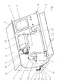
- the FIG. 1 shows the system (1) with a wet mill (2).
- the frame (3) consists of base frame (4) and half-shell (5).
- the processing machine here the wet mill (2) attached.
- the work area of the plant is designed as a half shell (5).
- the half-shell (5) is broken by the adapter (6). It picks up the console (7) with the control panel (8) at one end. This arrangement makes it easy to clean the work area.
- the Edge strips (9, 10) - the ends of the half-shell (5) - are used for fastening system parts (11, 12) via positive retaining members (13).
- the frame (3) is closed, has a removable, screw-on back panel and contains all components of the control, measuring and control technology.
- the pneumatic, hydraulic and electrical components such as pressure regulators, flow meters, drive controllers and microprocessor of the controller arranged.
- the central power supply of the system takes place via the back of the frame (3).
- the wet mill (2) has a cooling jacket which surrounds the grinding chamber (19) in order to dissipate the heat generated during the grinding.
- the sealing between the grinding chamber and the drive unit takes place via a mechanical seal.
- the internal circuits such as cooling the grinding chamber (19) and Gleitring machines with sealing liquid, via feeding and outgoing holes in the adapter and in the mill.
- the working fluid here water, is supplied to the system via the connection (15). Inside the frame (3), the working fluid is fed by control and measuring components electrically controlled the mill.
- the procedural parameters for the system (1) can be set or changed. This also causes the control to be switched to another machine variant.
- the system can also be equipped with a machine recognition, then the panel displays the control adapted to the machine.
- the peristaltic pump (20) attached to the console is used when the material to be ground is circulated in a cycle between the mill (2) and the feed tank (12).
- the mill motor is connected via a cable (21) with connector (22) to the console.
- the agitator (11) is speed controlled via a cable (23) connected to the socket (18).
- the feed tank (12) can be cooled via the cooling water supply (24) starting from the controlled output (17).
- the line (25) disposed of the return flow from the storage container (12).
- the cooling water for cooling the mill shell and for supplying the mechanical seal is returned via the adapter (6) to the mill (2) and back to the connection (16) and discharged together with the cooling water from the storage tank.
- the laboratory system is equipped with a dry-processing version such as classifier or classifier mill. Which is also connected via the adapter (6) with the system.
- the required, gaseous working medium is fed to the system via the connection (14) and via the adapter (6) of the processing machine.
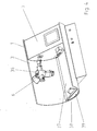
- FIG. 2 shows the frame (3) with the adapter (6) for attachment of the different preparation machines, which can be used optionally.
- the inlet and outlet bores (26) lead along with contour to the seal receptacle.
- the machine is supplied and disposed of with working fluids such as water and air.
- the machine is picked up on the specially designed adapter (27) and locked via the fastening screw (28) and the locking screw (29).
- the adapter (6) can be designed so that the conditioning machine can be rotated to different positions to aid in emptying or mounting.
- FIG. 3 shows a part of the system (1) in plan view with section through the adapter (6) and the frame.
- the pneumatic and hydraulic components (30) are shown in the area of the closed frame.
- the process-engineering machine is held by the adapter (6) and fixed with the screw (28) and locked with a locking screw.
- the adapter (6) consists of the holding tube (31) and the adapter core (32).
- the feeding and outgoing holes in the adapter (33) and the feeding and outgoing holes of the mill (34) and the ring line (35) of the rotary feedthrough are shown.
- FIG. 4 shows a frame variant (3) with separator (36), in which the electrical control is installed mainly in the console (7).
- the assembly takes place here over the bottom plate of the frame.
- a tray (37) can be inserted, which facilitates the cleaning, and the assembly and disassembly of the machine.
- material and media in the half-shell (5) located at its free end a barrier wall (38) with closable opening (39) for guided removal from the half-shell.
- the barrier wall (38) serves at the same time for receiving a tray (37), which is very helpful in dismantling the machines and transport of the items to the cleaning.
Landscapes
- Chemical & Material Sciences (AREA)
- General Health & Medical Sciences (AREA)
- Immunology (AREA)
- Health & Medical Sciences (AREA)
- Life Sciences & Earth Sciences (AREA)
- Food Science & Technology (AREA)
- Analytical Chemistry (AREA)
- Physics & Mathematics (AREA)
- Biochemistry (AREA)
- General Physics & Mathematics (AREA)
- Engineering & Computer Science (AREA)
- Pathology (AREA)
- Chemical Kinetics & Catalysis (AREA)
- Crushing And Pulverization Processes (AREA)
- Medicines Containing Plant Substances (AREA)
- Devices For Use In Laboratory Experiments (AREA)
- Crushing And Grinding (AREA)
Applications Claiming Priority (1)
| Application Number | Priority Date | Filing Date | Title |
|---|---|---|---|
| DE102009019868.7A DE102009019868B4 (de) | 2009-05-06 | 2009-05-06 | Verfahrenstechnische Anlage für den Laborbetrieb |
Publications (2)
| Publication Number | Publication Date |
|---|---|
| EP2248593A2 true EP2248593A2 (fr) | 2010-11-10 |
| EP2248593A3 EP2248593A3 (fr) | 2017-04-26 |
Family
ID=42352192
Family Applications (1)
| Application Number | Title | Priority Date | Filing Date |
|---|---|---|---|
| EP10004460.1A Withdrawn EP2248593A3 (fr) | 2009-05-06 | 2010-04-27 | Installation de procédé pour le fonctionnement en laboratoire |
Country Status (4)
| Country | Link |
|---|---|
| US (1) | US20100284242A1 (fr) |
| EP (1) | EP2248593A3 (fr) |
| JP (1) | JP2010260049A (fr) |
| DE (1) | DE102009019868B4 (fr) |
Cited By (1)
| Publication number | Priority date | Publication date | Assignee | Title |
|---|---|---|---|---|
| WO2025114084A1 (fr) * | 2023-11-27 | 2025-06-05 | Nexopart GmbH & Co. KG | Procédé pour faire fonctionner un broyeur de laboratoire et système de broyeur de laboratoire modulaire |
Families Citing this family (3)
| Publication number | Priority date | Publication date | Assignee | Title |
|---|---|---|---|---|
| DE102013006411B4 (de) * | 2013-04-13 | 2018-10-04 | Hosokawa Alpine Aktiengesellschaft | Verfahrenstechnische Maschine zur Installation in eine Wand |
| CN206343269U (zh) * | 2014-12-17 | 2017-07-21 | 菲活机器制造公司 | 用于执行多个破碎和研磨过程的模块化系统 |
| JP6359446B2 (ja) * | 2014-12-26 | 2018-07-18 | 株式会社パウレック | 粉粒体処理装置 |
Family Cites Families (21)
| Publication number | Priority date | Publication date | Assignee | Title |
|---|---|---|---|---|
| US3837810A (en) * | 1972-08-09 | 1974-09-24 | A Richards | Composter |
| JPS5991332A (ja) * | 1982-11-17 | 1984-05-26 | Nitsusoku Eng Kk | 複合環境試験装置 |
| US5219224A (en) * | 1986-02-26 | 1993-06-15 | Micro Chemical, Inc. | Programmable apparatus and method for delivering microingredient feed additives to animals by weight |
| US4815042A (en) * | 1986-02-26 | 1989-03-21 | Micro Chemical, Inc. | Programmable apparatus and method for delivering microingredient feed additives to animals by weight |
| JPH06160547A (ja) * | 1992-09-25 | 1994-06-07 | Kawaguchiko Seimitsu Kk | 時計の曜日板 |
| US5520456A (en) * | 1993-06-16 | 1996-05-28 | Bickerstaff; Richard D. | Apparatus for homogeneous mixing of two media having an elongated cylindrical passage and media injection means |
| US5370178A (en) * | 1993-08-25 | 1994-12-06 | International Business Machines Corporation | Convertible cooling module for air or water cooling of electronic circuit components |
| US5482113A (en) * | 1993-08-25 | 1996-01-09 | International Business Machines Corporation | Convertible heat exchanger for air or water cooling of electronic circuit components and the like |
| DE4401679C2 (de) * | 1994-01-21 | 1996-04-18 | Janke & Kunkel Kg | Rührgerät mit einer Haltevorrichtung |
| US5618090A (en) * | 1995-05-12 | 1997-04-08 | Medaes, Inc. | Movable hospital room equipment column |
| EP1185371B2 (fr) * | 1999-06-01 | 2008-11-12 | Elan Pharma International Limited | Broyeur reduit et procede associe |
| DE60123254T2 (de) * | 2000-07-31 | 2007-09-06 | Kinetics Chempure Systems, Inc., Tempe | Verfahren und vorrichtung zum mischen von prozessmaterialien |
| DE10057556A1 (de) * | 2000-11-21 | 2002-05-23 | Kreuzer Gmbh & Co Ohg | Stativkopf, insbesondere für eine medizinische Überwachungs- und Versorgungseinrichtung, Trägerprofil für einen solchen und Gerätewagen |
| JP2003101316A (ja) * | 2001-09-20 | 2003-04-04 | Nippon Antenna Co Ltd | 携帯無線機用アンテナ |
| US7097787B2 (en) * | 2002-07-19 | 2006-08-29 | Conocophillips Company | Utilization of micro-channel gas distributor to distribute unreacted feed gas into reactors |
| JP2005123962A (ja) * | 2003-10-17 | 2005-05-12 | Nippon Antenna Co Ltd | 携帯無線機用アンテナ |
| JP4761497B2 (ja) * | 2004-04-15 | 2011-08-31 | 株式会社ダルトン | アイソレーター |
| US7090098B2 (en) * | 2004-05-06 | 2006-08-15 | Johnsondiversey, Inc. | Metering and dispensing closure |
| US7815072B2 (en) * | 2004-05-06 | 2010-10-19 | Diversey, Inc. | Metering and dispensing closure |
| WO2007139746A1 (fr) * | 2006-05-22 | 2007-12-06 | Biovest International Inc. | Soupape d'actionneur rotatif pour un système de culture cellulaire |
| DE102006052804B4 (de) * | 2006-11-09 | 2010-07-29 | Dräger Medical AG & Co. KG | Tragevorrichtung |
-
2009
- 2009-05-06 DE DE102009019868.7A patent/DE102009019868B4/de not_active Expired - Fee Related
-
2010
- 2010-04-27 US US12/768,648 patent/US20100284242A1/en not_active Abandoned
- 2010-04-27 EP EP10004460.1A patent/EP2248593A3/fr not_active Withdrawn
- 2010-05-06 JP JP2010106153A patent/JP2010260049A/ja active Pending
Non-Patent Citations (1)
| Title |
|---|
| None |
Cited By (1)
| Publication number | Priority date | Publication date | Assignee | Title |
|---|---|---|---|---|
| WO2025114084A1 (fr) * | 2023-11-27 | 2025-06-05 | Nexopart GmbH & Co. KG | Procédé pour faire fonctionner un broyeur de laboratoire et système de broyeur de laboratoire modulaire |
Also Published As
| Publication number | Publication date |
|---|---|
| DE102009019868B4 (de) | 2015-10-22 |
| EP2248593A3 (fr) | 2017-04-26 |
| US20100284242A1 (en) | 2010-11-11 |
| DE102009019868A1 (de) | 2010-11-18 |
| JP2010260049A (ja) | 2010-11-18 |
Similar Documents
| Publication | Publication Date | Title |
|---|---|---|
| DE102009019868B4 (de) | Verfahrenstechnische Anlage für den Laborbetrieb | |
| DE69101653T2 (de) | Vorrichtung zur Vorbehandlung von Kunststoffabfällen vor ihrer Wiederaufbereitung. | |
| DE112007003430T5 (de) | Vorrichtung zur Behandlung von Ballastwasser mit wässriger Acroleinlösung | |
| EP2192392A2 (fr) | Dispositif de dosage doté d'un dispositif de réception pour une unité insérable | |
| JP4909353B2 (ja) | ポリウレタン設備に用いられる添加剤調量装置 | |
| CH667221A5 (de) | Desintegratoranlage. | |
| CN216368276U (zh) | 一种堆肥法土壤修复用肥料生产装置 | |
| EP2950918A1 (fr) | Unité de traitement et utilisation de plusieurs unités de traitement | |
| CN113061721A (zh) | 一种稀土加工用搅拌联动萃取装置 | |
| DE2554389A1 (de) | Geraet zum mahlen mittels sand | |
| EP1679448B1 (fr) | Dispositif pour l'élaboration de matériaux en vrac | |
| KR200195935Y1 (ko) | 고추 분쇄장치 | |
| CN215353218U (zh) | 一种化工原料搅拌设备 | |
| EP3214387B1 (fr) | Appareil de préparation d'eau portatif pour l'humidification de l'air et partie stationaire de l'humidification | |
| CN212791253U (zh) | 一种复混肥料生产设备 | |
| DE3820281A1 (de) | Materialzufuehreinrichtung fuer kunststoffverarbeitungsmaschinen | |
| CN112452201A (zh) | 一种水泥生产线用物料储存防停机持续供给装置 | |
| CN210845998U (zh) | 一种二极管加工用清洗液配制装置 | |
| CN212581579U (zh) | 一种mpp一体化污水处理设备 | |
| CN216654137U (zh) | 一种天然精油原料混合搅拌装置 | |
| CN220990607U (zh) | 一种营养添加剂的粉碎混合机 | |
| CN214637150U (zh) | 一种组合式多功能破碎机维保工具 | |
| CN221051699U (zh) | 一种循环水自动加药装置 | |
| CN210683307U (zh) | 一种环境保护用泔水处理装置 | |
| CN213140274U (zh) | 一种螺旋进料装置 |
Legal Events
| Date | Code | Title | Description |
|---|---|---|---|
| PUAI | Public reference made under article 153(3) epc to a published international application that has entered the european phase |
Free format text: ORIGINAL CODE: 0009012 |
|
| AK | Designated contracting states |
Kind code of ref document: A2 Designated state(s): AT BE BG CH CY CZ DE DK EE ES FI FR GB GR HR HU IE IS IT LI LT LU LV MC MK MT NL NO PL PT RO SE SI SK SM TR |
|
| AX | Request for extension of the european patent |
Extension state: AL BA ME RS |
|
| PUAL | Search report despatched |
Free format text: ORIGINAL CODE: 0009013 |
|
| AK | Designated contracting states |
Kind code of ref document: A3 Designated state(s): AT BE BG CH CY CZ DE DK EE ES FI FR GB GR HR HU IE IS IT LI LT LU LV MC MK MT NL NO PL PT RO SE SI SK SM TR |
|
| AX | Request for extension of the european patent |
Extension state: AL BA ME RS |
|
| RIC1 | Information provided on ipc code assigned before grant |
Ipc: B02C 17/18 20060101AFI20170320BHEP Ipc: B07B 11/06 20060101ALI20170320BHEP Ipc: B07B 7/083 20060101ALI20170320BHEP Ipc: G01N 1/28 20060101ALI20170320BHEP Ipc: B01F 7/16 20060101ALI20170320BHEP |
|
| STAA | Information on the status of an ep patent application or granted ep patent |
Free format text: STATUS: THE APPLICATION IS DEEMED TO BE WITHDRAWN |
|
| 18D | Application deemed to be withdrawn |
Effective date: 20171027 |