EP2247449B1 - Détection de colorants dans un liquide support - Google Patents
Détection de colorants dans un liquide support Download PDFInfo
- Publication number
- EP2247449B1 EP2247449B1 EP08731186.6A EP08731186A EP2247449B1 EP 2247449 B1 EP2247449 B1 EP 2247449B1 EP 08731186 A EP08731186 A EP 08731186A EP 2247449 B1 EP2247449 B1 EP 2247449B1
- Authority
- EP
- European Patent Office
- Prior art keywords
- light
- colorants
- light sources
- detectors
- sources
- Prior art date
- Legal status (The legal status is an assumption and is not a legal conclusion. Google has not performed a legal analysis and makes no representation as to the accuracy of the status listed.)
- Not-in-force
Links
- 239000003086 colorant Substances 0.000 title claims description 134
- 239000007788 liquid Substances 0.000 title claims description 56
- 238000000034 method Methods 0.000 claims description 28
- 239000002245 particle Substances 0.000 claims description 14
- 239000007787 solid Substances 0.000 claims description 7
- 239000000049 pigment Substances 0.000 claims description 6
- 238000010586 diagram Methods 0.000 description 7
- 238000001514 detection method Methods 0.000 description 6
- 239000006185 dispersion Substances 0.000 description 4
- 238000010894 electron beam technology Methods 0.000 description 2
- 238000010521 absorption reaction Methods 0.000 description 1
- 238000011088 calibration curve Methods 0.000 description 1
- 239000012141 concentrate Substances 0.000 description 1
- 230000001419 dependent effect Effects 0.000 description 1
- 239000000975 dye Substances 0.000 description 1
- 238000000684 flow cytometry Methods 0.000 description 1
- 239000012530 fluid Substances 0.000 description 1
- 238000012886 linear function Methods 0.000 description 1
- 239000000463 material Substances 0.000 description 1
- 238000012544 monitoring process Methods 0.000 description 1
- 230000003287 optical effect Effects 0.000 description 1
- 230000010287 polarization Effects 0.000 description 1
Images


Classifications
-
- G—PHYSICS
- G03—PHOTOGRAPHY; CINEMATOGRAPHY; ANALOGOUS TECHNIQUES USING WAVES OTHER THAN OPTICAL WAVES; ELECTROGRAPHY; HOLOGRAPHY
- G03G—ELECTROGRAPHY; ELECTROPHOTOGRAPHY; MAGNETOGRAPHY
- G03G15/00—Apparatus for electrographic processes using a charge pattern
- G03G15/06—Apparatus for electrographic processes using a charge pattern for developing
- G03G15/08—Apparatus for electrographic processes using a charge pattern for developing using a solid developer, e.g. powder developer
- G03G15/0822—Arrangements for preparing, mixing, supplying or dispensing developer
- G03G15/0848—Arrangements for testing or measuring developer properties or quality, e.g. charge, size, flowability
- G03G15/0849—Detection or control means for the developer concentration
- G03G15/0855—Detection or control means for the developer concentration the concentration being measured by optical means
-
- G—PHYSICS
- G03—PHOTOGRAPHY; CINEMATOGRAPHY; ANALOGOUS TECHNIQUES USING WAVES OTHER THAN OPTICAL WAVES; ELECTROGRAPHY; HOLOGRAPHY
- G03G—ELECTROGRAPHY; ELECTROPHOTOGRAPHY; MAGNETOGRAPHY
- G03G15/00—Apparatus for electrographic processes using a charge pattern
- G03G15/06—Apparatus for electrographic processes using a charge pattern for developing
- G03G15/10—Apparatus for electrographic processes using a charge pattern for developing using a liquid developer
- G03G15/104—Preparing, mixing, transporting or dispensing developer
- G03G15/105—Detection or control means for the toner concentration
Definitions
- An electro-photography (EP) printing device forms an image on media typically by first selectively charging a photoconductive drum in correspondence with the image. Colorant is applied to the photoconductive drum where the drum has not been charged, and then this colorant is transferred to the media to form the image on the media.
- EP printing device has been the laser printer, which is a dry EP (DEP) printing device that employs toner as the colorant in question.
- DEP dry EP
- LEP liquid EP
- An LEP printing device employs ink, instead of toner, as the colorant that is applied to the photoconductive drum where the drum has been charged.
- the ink includes solid pigment particles within a carrier liquid.
- the concentration of the solid pigment particles within the carrier liquid is desirably maintained at a substantially constant level for a given type of ink.
- the concentration of the colorants within the carrier liquid is desirably measured.
- WO 94/01756 A1 discloses a method and an apparatus for detecting concentrations of toner particles in a dispersion, including illuminating the dispersion with linearly polarized light, detecting an amount of light passed through the dispersion and through an analyzer set at a predetermined angle to the given polarization direction and determining the concentration of one of the toner particles utilizing the detected amount of light. Additionally, the dispersion can be illuminated with unpolarized light for detecting the particles in the absence or presence of scatter and absorption.
- EP 0 165 802 A2 describes a method and an apparatus for monitoring concentrate material in a fluid carrier, including a flow cell and an LED on one side of the flow cell and a photodetector on the other side of the flow cell, defining a transmitted light path therebetween.
- US 2004/0145725 A1 describes an optical detection system for flow cytometry, including a hydro-dynamic flow block, with a number of light emitters on one side of a flow path and a number of light detectors on the opposite side of the flow path. The light emitters and light detectors are aligned relative to one another.
- the present invention provides a detecting apparatus according to claim 1 and/or 3 and a method according to claim 8 and/or 10. Embodiments of the invention are defined in the dependent claims.
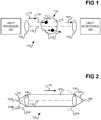
- FIG. 1 shows a detecting apparatus 100 to at least assist in determining the concentration of colorants 112 within a carrier liquid 114, according to an embodiment of the present disclosure.
- the detecting apparatus 100 may be part of a liquid electro-photography (LEP) printing device.
- the colorants 112 and the carrier liquid 114 are part of ink 110 that is used by the LEP printing device to form images on media like paper in an LEP manner.
- the colorants 112 in this embodiment are particularly solid pigment particles that provide the ink 110 with its desired color, where the carrier liquid 114 of the ink 110 may be oil.
- the colorants 112 may be other types of colorants, however, such as non-solid dyes.
- the detecting apparatus 100 of the embodiment of FIG. 1 includes one or more lenses 106 and one or more lenses 108.
- the transmitted light path has an emitting end at which the lenses 106 are situated, and a detecting end at which the lenses 108 are situated.
- the transmitted light path denoted by the arrow 118 has a linear axis 116 between the lenses 106 and 108 as well.
- the detecting apparatus 100 includes one or more light sources 102 and one or more light detectors 104.
- the light sources 102 may be light-emitting diodes (LED's), laser light sources, and/or other types of energy sources, such that the terminology light sources as used herein also encompasses energy sources like electron beams.
- the light sources 102 are positioned at or near the emitting end of the transmitted light path denoted by the arrow 118.
- the light detectors 104 may be photodiodes, and/or other types of energy detectors, where the terminology detectors as used herein encompasses energy detectors for detecting electron beams and other types of energy.
- the light detectors 104 are positioned at or near the detecting end of the transmitted light path denoted by the arrow 118.
- the light sources 102 emit light, while the light detectors 104 detect light.
- the carrier liquid 114 containing the colorants 112 travels through the transmitted light path denoted by the arrow 118.
- the carrier liquid 114 and thus the colorants 112 may be ejected through the plane of the sheet of FIG. 1 , between the lenses 106 and 108 and thus through the transmitted light path denoted by the arrow 118. That is, if the x-axis (i.e., the axis 116) and the y-axis define the plane of FIG. 1 , the carrier liquid 114 and the colorants 112 are ejected along the z-axis that is perpendicular to the plane of FIG.
- Light emitted by the light sources 102 which may or may not be emitted along the transmitted light path denoted by the arrow 118 as is described later in the detailed description, may be affected or unaffected by the colorants 112 within the carrier liquid 114 in any of three different ways.
- first scenario is representatively depicted in FIG. 1 by the arrow 124.
- Second, light that is directly emitted by the light sources 102 along the transmitted light path denoted by the arrow 118 may encounter and be absorbed by the colorants 112 within the carrier liquid 114.
- This second scenario is representatively depicted in FIG. 1 by the arrow 120. Light absorbed by the colorants 112 in this scenario do not reach the light detectors 104, and are not detected by the light detectors 104.
- light that is emitted by the light sources 102 may encounter and be diverged by the colorants 112 within the carrier liquid 114.
- This third scenario is representatively depicted in FIG. 1 by the arrows 122.
- light diverged by the colorants 112 may reach the light detectors 104, and thus may be detected by the light detectors 104.
- Divergence in this sense can mean that the light is fluoresced and/or scattered by the colorants 112.
- Scattering means that the light changes direction when encountering the colorants 112.
- Fluorescence means that the light changes forms of energy when encountering the colorants 112 and also changes its original direction.
- FIG. 2 shows the apparatus 100, according to a first specific embodiment of the present disclosure.
- the light sources 102 are divided into two groups: one or more first light sources 102A and one or more second light sources 102B.
- the light detectors 104 have not been divided into separate groups.
- the first light sources 102A are positioned at the emitting end of the transmitted light path denoted by the arrow 118, and more specifically along the axis 116 of the transmitted light path. This can mean, for instance, that the light sources 102A may be positioned at the focal point of the lenses 106, at the center of the lenses 106 from top to bottom in FIG. 2 .
- the first light sources 102A therefore directly emit only light 202 that travels along the transmitted light path denoted by the arrow 118 except where the emitted light is absorbed or diverged by colorants.
- the first light sources 102A do not emit any light that does not travel along the transmitted light path denoted by the arrow 118, unless (i.e., except) of course the light emitted by the first light sources 102A is diverged or absorbed by colorants.
- the second light sources 102B are positioned near the emitting end of the transmitted light path denoted by the arrow 118, and more specifically are not positioned along the axis 116 of the transmitted light path. This can mean, for instance, that the light sources 102B may be positioned off-center relative to the lenses 106 from top to bottom in FIG. 2 , and may not be positioned at the focal point of the lenses 106. The second light sources 102B therefore emit light 204 that does not travel along the transmitted light path denoted by the arrow 118.
- the light detectors 104 are positioned at the detecting end of the transmitted light path denoted by the arrow 118, and more specifically along the axis 116 of the transmitted light path. For instance, the light detectors 104 may be positioned at the focal point of the lenses 108, at the center of the lenses 108 from top to bottom in FIG. 2 .
- the light detectors 104 detect the light 202 directly emitted by the first light sources 102A that has not been absorbed or diverged by colorants.
- the light detectors 104 also detect the light 204 emitted by the second light sources 102B that have been diverged by colorants towards the light detectors 104.
- FIG. 3 shows a method 300 in relation to which the apparatus 100 of FIG. 2 can be used, according to an embodiment of the present disclosure.
- the first light sources 102A are positioned at the emitting end of the transmitted light path denoted by the arrow 118, along the axis 116 of the transmitted light path (302).
- the second light sources 102B are positioned near the emitting end of the transmitted light path denoted by the arrow 118, but not along the axis 116 of the transmitted light path (304).
- the light detectors 104 are positioned at the detecting end of the transmitted light path denoted by the arrow 118, also along the axis 116 of the transmitted light path (306).
- the first light sources 102A and the second light sources 102B are alternatingly turned on and off (308). That is, when the first light sources 102A are turned on to emit the light 202, the second light sources 102B are turned off and do not emit the light 204. Similarly, when the second light sources 102B are turned on to emit the light 204, the first light sources 102A are turned off and do not emit the light 202. Thus, at any given time, either the first light sources 102A are on and the second light sources 102B are off, or the first light sources 102A are off and the second light sources 102B are on.
- the light detectors 104 detect the light 202 directly emitted by the first light sources 102A along the transmitted path denoted by the arrow 118 and that has not been absorbed or diverged by colorants (310). The detection of this light may include measuring or providing a value corresponding to the intensity of the light detected. Similarly, when the first light sources 102A are off and the second light sources 102B are on, the light detectors 104 detect the light 204 emitted by the second light sources 102B that has been diverged by colorants towards the light detectors 104 (312). The detection of this light may also include measuring or providing a value corresponding to the intensity of the light detected.
- the measure of the light 202 that has not been absorbed or diverged by colorants, as detected, is processed in relation to the measure of the light 204 that has been diverged by colorants, as detected (314). This process is achieved to at least assist in determining the concentration of the colorants within the carrier liquid, as is understood and can be appreciated by those of ordinary skill within the art. Embodiments of the present disclosure are not limited to the manner by which these measures of light are processed in relation to one another to at least assist in determining the concentration of the colorants within the carrier liquid.
- FIG. 4 shows the apparatus 100, according to a second specific embodiment of the present disclosure
- FIG. 5 shows the apparatus 100, according to a third specific embodiment of the present disclosure
- the light detectors 104 are divided into two groups: one or more first light detectors 104A, and one or more second light detectors 104B.
- the light sources 102 have not been divided into separate groups.
- the difference between the embodiments of FIGs. 4 and 5 is that the embodiment of FIG. 5 includes a mirror 504, while the embodiment of FIG. 4 does not include a mirror.
- the light sources 102 are positioned at the emitting end of the transmitted light path denoted by the arrow 118, and more specifically along the axis 116 of the transmitted light path. This can mean, for instance, that the light sources 102 may be positioned at the focal point of the lenses 106, at the center of the lenses 106 from top to bottom in FIGs. 4 and 5 .
- the light sources 102 directly emit only light 202 that travels along the transmitted light path denoted by the arrow 118, except where the emitted light is absorbed or diverged by colorants.
- the light sources 102 do not emit any light that does not travel along the transmitted light path denoted by the arrow 118, unless (i.e., except) of course the light emitted by the first light sources 102A is diverged or absorbed by colorants.
- the first light detectors 104A are positioned at the detecting end of the transmitted light path denoted by the arrow 118, and more specifically along the axis 116 of the transmitted light path. This can mean, for instance, that the first light detectors 104A may be positioned at the focal point of the lenses 108, at the center of the lenses 108 from top to bottom in FIGs. 4 and 5 .
- the first light detectors 104A detect the light 202 directly emitted by the light sources 102 that has not been absorbed or diverged by colorants.
- the first light detectors 104A otherwise do not detect any light, such as any light that does not travel along the transmitted light path.
- the second light detectors 104B are positioned near the detecting end of the transmitted light path denoted by the arrow 118, and more specifically are not positioned along the axis 116 of the transmitted light path. This can mean, for instance, that the second light detectors 104B may be positioned off-center relative to the lenses 108 from top to bottom in FIGs. 4 and 5 .
- the second light detectors 104B detect the light emitted by the light sources 102 that has been diverged by colorants, which is indicated in FIGs. 4 and 5 as the light 402.
- the second light detectors 104B otherwise do not detect any light, such as the directly emitted light 202 that travels along the transmitted light path and that has not been absorbed or diverged by colorants.
- the mirror 504 is positioned in relation to the second light detectors 104B to reflect the light that has been emitted by the light sources 102 and that has been diverged by colorants, which is indicated as the light 402, towards the second light detectors 104B.
- the embodiment of FIG. 5 may afford greater detection of the light 402 diverged by the colorants by the second light detectors 104B as compared to the embodiment of FIG. 4 . This is because the mirror 504 reflects the light 402 diverged by the colorants towards the second light reflectors 104B in the embodiment of FIG. 5 .
- FIG. 6 shows a method 600 in relation to which the apparatus 100 of FIG. 4 or FIG. 5 can be used, according to an embodiment of the present disclosure.
- the light sources 102 are positioned at the emitting end of the transmitted light path denoted by the arrow 118, along the axis 116 of the transmitted light path (602).
- the first light detectors 104A are positioned at the detecting end of the transmitted light path denoted by the arrow 118, also along the axis 116 of the transmitted light path (604).
- the second light detectors 104B are positioned near the detecting end of the transmitted light path denoted by the arrow 118, and not along the axis 116 of the transmitted light path (606).
- the mirror 504 is positioned in relation to the second light detectors 104B to reflect light emitted by the light sources 102 and that has been diverged by colorants towards the second light detectors 104B, as has been described.
- the light sources 102 are turned on at substantially the same time to emit light (610).
- the first light detectors 104A detect the light 202 that has been directly emitted by the light sources 102 along the transmitted path denoted by the arrow 118 and that has not been absorbed or diverged by colorants (612). The detection of this light may include measuring or providing a value corresponding to the intensity of the light detected.
- the second light detectors 104B detect the light 402 that has been emitted by the light sources 102 but that has been diverged by colorants (614). The detection of this light may also include measuring or providing a value corresponding to the intensity of the light detected.
- the measure of the light 202 that has not been absorbed or diverged by colorants, as detected, is processed in relation to the measure of the light 402 that has been diverged by colorants, as detected (314). This process is achieved to at least assist in determining the concentration of the colorants within the carrier liquid, as is understood and can be appreciated by those of ordinary skill within the art. As has been noted, embodiments of the present disclosure are not limited to the manner by which these measures of light are processed in relation to one another to at least assist in determining the concentration of the colorants within the carrier liquid.
- FIG. 7 shows a method 700 that summarizes the operation of the apparatus 100 of any of the embodiments of FIGs. 1, 2 , 4, and 5 , according to an embodiment of the disclosure.
- the method 700 thus encompasses and is more general than the method 300 of FIG. 3 and the method 600 of FIG. 6 .
- a transmitted light path is defined as having an emitting end and a detecting end (702).
- Part 702 may include providing and positionally configuring the lenses 106 and 108 that have been described, for instance.
- the light sources 102 and the light detectors 104 are positionally configured in relation to one another relative to the transmitted light path that has been defined (704). Specifically, such positional configuration is achieved so that the light detectors 104 detect both the light directly emitted by the light sources 102 along the transmitted light path and that has not been absorbed by the colorants, as well as the light diverged by the colorants.
- Such positional configuration can be achieved in specific embodiments, for instance, as has been described in relation to FIG. 2 , FIG. 4 , and/or FIG. 5 .
- part 704 encompasses parts 302, 304, and 306 of the method 300 of FIG. 3 , as well as parts 602, 604, 606, and 608 of the method 600 of FIG. 6 .
- the light sources 102 then emit light (706), such as has been described in relation to part 308 of the method 300 of FIG. 3 or in relation to part 610 of the method 600 of FIG. 6 .
- the light detectors 104 detect the light directly emitted by the light sources 102 along the transmitted light path and that has not been absorbed by the colorants, as well as the light diverged by the colorants (708).
- part 708 encompasses parts 310 and 312 of the method 300, as well as parts 612 and 614 of the method 600.
- the measure of the light directly emitted along the transmitted light path that has not been absorbed or diverged by colorants, as detected is processed in relation to the measure of the light that has been diverged by colorants, as detected (616).
- This process is achieved to at least assist in determining the concentration of the colorants within the carrier liquid, as is understood and can be appreciated by those of ordinary skill within the art.
- embodiments of the present disclosure are not limited to the manner by which these measures of light are processed in relation to one another to at least assist in determining the concentration of the colorants within the carrier liquid.
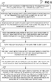
- FIG. 8 shows a block diagram of a rudimentary LEP printing device 800, according to an embodiment of the present disclosure.
- the LEP printing device 800 can be a standalone printing device having just printing functionality, or a multiple-function device (MFD) or an all-in-one (AIO) device having other functionality, such as scanning, copying, and/or faxing functionality, in addition to having printing functionality.
- the LEP printing device 800 is depicted in FIG. 8 as including an LEP printing mechanism 802 and the detecting apparatus 100 of FIGs. 1, 2 , 4 , and/or 5 that has been described.
- the LEP printing device 800 may include other components, in addition to and/or in lieu of those depicted in FIG. 8 .
- the LEP printing mechanism 802 prints images on media like paper by using LEP, in relation to the ink 110 having the solid (pigment) particles 112 within the carrier liquid 110, as can be appreciated by those of ordinary skill within the art.
- the LEP printing mechanism 802 may include a binary ink developer and other components typically and/or commonly found within LEP printing devices like the LEP printing device 800.
- the colorants 112 absorb and/or diverge light.
- the detecting apparatus 100 is thus used to at least assist in determining the concentration of the colorants 112 within the carrier liquid 114, by detecting a measure of light that passes through ink 110 without being absorbed or diverged by the colorants 112 and by detecting a measure of light that is diverged by the colorants 112. These measures of light can be processed in relation to one another to determine or calculate the concentration of the colorants 112 within the carrier liquid 114. In this way, the concentration of the colorants 112 within the carrier liquid 114 can be monitored, so that it is maintained at a substantially constant level for a given type of the ink 110 in order to ensure optimal and/or proper LEP printing by the LEP printing mechanism 802.
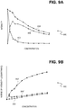
- FIGs. 9A and 9B show graph 900 and 950, respectively of detected light intensity as a function of colorant concentration, according to an embodiment of the present disclosure, and which depicts the advantages provided by embodiments of the present disclosure.
- the graph 900 specifically depicts light intensity as a function of colorant concentration
- the graph specifically depicts the logarithm of the inverse of light intensity as a function of colorant concentration.
- the lines 902 and 902' denote detected light that has not been diverged or absorbed by colorant particles.
- the lines 904 and 904' denote detected light that has been diverged by colorant particles.
- the lines 906 and 906' denote a weighted sum of the detected light that has not been diverged or absorbed by colorant particles and the light that has been diverged by colorant particles.
- the lines 902, 902', 904, 904', and 906' are non-linear.
- the line 906' is linear.
- embodiments of the present disclosure provide for a significantly decrease dependence of the colorant concentration on the nature of the light inclination mechanism of the colorant, such as particle size, shape, and/or refraction index.
- the light detected by the various detector(s) of embodiments of the present disclosure provides the signal represented by the line 906' in FIG. 9B in particular that depends just on the colorant concentration.
- colorant concentration determination is simplified.
- embodiments of the present disclosure provide for a substantially linear dependence of the logarithm of the inverse of the weighted sum of the detector signals, as has been described above. This permits a significantly simplified process of constructing calibration curves and procedures. For this reason as well, colorant concentration determination is also simplified.
Landscapes
- Physics & Mathematics (AREA)
- General Physics & Mathematics (AREA)
- Investigating Or Analysing Materials By Optical Means (AREA)
- Eyeglasses (AREA)
Claims (11)
- Appareil de détection (100) pour aider au moins à déterminer une concentration de colorants (112) à l'intérieur d'un liquide porteur (114), les colorants absorbant au moins la lumière et/ou la lumière divergente, comprenant :une ou plusieurs sources de lumière (102) pour émettre de la lumière ; etun ou plusieurs détecteurs de lumière (104) pour détecter la lumière,les sources de lumière (102) et les détecteurs de lumière (104) étant configurés en position les uns par rapport aux autres de sorte que la lumière directement émise par les sources de lumière (102) et qui n'a pas été absorbée ou déviée par les colorants (112), ainsi que la lumière déviée par les colorants (112) à l'intérieur du liquide porteur (114), sont toutes deux détectées et/ou déterminées,de sorte que la concentration de colorants (112) est déterminée sur la base de la lumière directement émise par les sources de lumière (102) qui n'a pas été absorbée ou déviée par les colorants (112) et/ou sur la base de la lumière déviée par les colorants (112) à l'intérieur du liquide porteur,l'appareil de détection (100) définissant un trajet de lumière transmise (118) ayant une extrémité d'émission et une extrémité de détection, de sorte que la lumière directement émise par les sources de lumière (102) et qui n'a pas été absorbée ou déviée par les colorants (112) est émise au niveau de l'extrémité d'émission du trajet de lumière transmise (118) et est détectée au niveau de l'extrémité de détection du trajet de lumière transmise (118), les sources de lumière (102) comprenant :une ou plusieurs premières sources de lumière (102A) pour émettre une lumière qui se déplace le long du trajet de lumière transmise (118), les premières sources de lumière (102A) étant positionnées au niveau de l'extrémité d'émission du trajet de lumière transmise (118), les premières sources de lumière (102A) étant positionnées le long d'un axe du trajet de lumière transmise (118), l'axe du trajet de lumière transmise (118) s'étendant entre l'extrémité d'émission et l'extrémité de détection du trajet de lumière transmise (118) ; etune ou plusieurs secondes sources de lumière (102B) pour émettre une lumière qui ne se déplace pas le long du trajet de lumière transmise (118), les secondes sources de lumière (102B) étant positionnées à proximité de l'extrémité d'émission du trajet de lumière transmise (118), les secondes sources de lumière (102B) n'étant pas positionnées le long de l'axe du trajet de lumière transmise (118),les premières sources de lumière (102A) n'émettant aucune lumière qui ne se déplace pas le long du trajet de lumière transmise (118) sauf si la lumière est déviée ou absorbée par les colorants (112) et les secondes sources de lumière (102B) n'émettant aucune lumière qui se déplace le long du trajet de lumière transmise (118),et les détecteurs de lumière (104) étant positionnés au niveau de l'extrémité de détection du trajet de lumière transmise (118), et les détecteurs de lumière (104) étant positionnés le long de l'axe du trajet de lumière transmise (118),les détecteurs de lumière (104) détectant la lumière émise par les premières sources de lumière (102A) et qui n'a pas été absorbée ou déviée par les colorants (112), etles détecteurs de lumière (104) détectant la lumière émise par les secondes sources de lumière (102B) et qui a été déviée par les colorants (112) à l'intérieur du liquide porteur (114) ;l'appareil de détection comprenant en outre :une ou plusieurs premières lentilles (106) au niveau de l'extrémité d'émission du trajet de lumière transmise (118) ; et,une ou plusieurs secondes lentilles (108) au niveau de l'extrémité de détection du trajet de lumière transmise (118) et situées à l'opposé des premières lentilles (106), de sorte que les premières lentilles (106) et les secondes lentilles (108) définissent le trajet de lumière transmise (118).
- Appareil de détection selon la revendication 1, dans lequel les premières sources de lumière (102A) et les secondes sources de lumière (102B) sont allumées et éteintes en alternance, de sorte que lorsque les premières sources de lumière (102A) sont allumées, les secondes sources de lumière (102B) sont éteintes, et que lorsque les premières sources de lumière (102A) sont éteintes, les secondes sources de lumière (102B) sont allumées,
les détecteurs de lumière (104) détectant la lumière émise par les premières sources de lumière (102A) et qui n'a pas été absorbée ou déviée par les colorants (112) lorsque les premières sources de lumière (102A) sont allumées et que les secondes sources de lumière (102B) sont éteintes, et
les détecteurs de lumière (104) détectant la lumière émise par les secondes sources de lumière (102B) et qui a été déviée par les colorants (112) à l'intérieur du liquide porteur (114) lorsque les secondes sources de lumière (102B) sont allumées et que les premières sources de lumière (102A) sont éteintes. - Appareil de détection (100) pour aider au moins à déterminer une concentration de colorants (112) à l'intérieur d'un liquide porteur (114), les colorants absorbant au moins la lumière et/ou la lumière divergente, comprenant :une ou plusieurs sources de lumière (102) pour émettre de la lumière ; et,un ou plusieurs détecteurs de lumière (104) pour détecter la lumière,les sources de lumière (102) et les détecteurs de lumière (104) étant configurés en position les uns par rapport aux autres de sorte que la lumière directement émise par les sources de lumière (102) et qui n'a pas été absorbée ou déviée par les colorants (112), ainsi que la lumière déviée par les colorants (112) à l'intérieur du liquide porteur (114), sont toutes deux détectées et/ou déterminées,de sorte que la concentration de colorants (112) est déterminée sur la base de la lumière directement émise par les sources de lumière (102) qui n'a pas été absorbée ou déviée par les colorants (112) et/ou sur la base de la lumière déviée par les colorants (112) à l'intérieur du liquide porteur (114),l'appareil de détection (100) définissant un trajet de lumière transmise (118) ayant une extrémité d'émission et une extrémité de détection, de sorte que la lumière directement émise par les sources de lumière (102) et qui n'a pas été absorbée ou déviée par les colorants (112) est émise au niveau de l'extrémité d'émission du trajet de lumière transmise (118) et est détectée au niveau de l'extrémité de détection du trajet de lumière transmise (118),les sources de lumière (102) n'émettant que de la lumière qui se déplace le long du trajet de lumière transmise (118) sauf si la lumière est déviée ou absorbée par les colorants (112), les sources de lumière (102) n'émettant aucune lumière qui ne se déplace pas le long du trajet de lumière transmise (118), sauf si la lumière est déviée ou absorbée par les colorants (112), les sources de lumière (102) étant positionnées au niveau de l'extrémité d'émission du trajet de lumière transmise (118), les sources de lumière (102) étant positionnées le long d'un axe du trajet de lumière transmise (118), l'axe du trajet de lumière transmise (118) s'étendant entre l'extrémité d'émission et l'extrémité de détection du trajet de lumière transmise (118) ; etles détecteurs de lumière (104) comprenant :un ou plusieurs premiers détecteurs de lumière (104A) pour détecter la lumière émise par les sources de lumière (102) et qui n'a pas été absorbée ou déviée par les colorants (112), les premiers détecteurs de lumière (104A) étant positionnés au niveau de l'extrémité de détection du trajet de lumière transmise (118), les premiers détecteurs de lumière (104A) étant positionnés le long de l'axe du trajet de lumière transmis (118) ; et,un ou plusieurs seconds détecteurs de lumière (104B) pour détecter la lumière émise par les sources de lumière (102) et qui a été déviée par les colorants (112) à l'intérieur du liquide porteur (114),les premiers détecteurs de lumière (104A) ne détectant aucune lumière qui ne se déplace pas le long du trajet de lumière transmise (118) et les seconds détecteurs de lumière (104B) ne détectant aucune lumière qui se déplace le long du trajet de lumière transmise (118).
- Appareil de détection selon la revendication 3, dans lequel les seconds détecteurs de lumière (104B) sont positionnés à proximité de l'extrémité de détection du trajet de lumière transmise (118) et les seconds détecteurs de lumière (104B) ne sont pas positionnés le long de l'axe du trajet de lumière transmise.
- Appareil de détection selon la revendication 3 ou 4, comprenant en outre un miroir (504) pour réfléchir la lumière émise par les sources de lumière (102) et qui a été déviée par les colorants (112) à l'intérieur du liquide porteur (114) vers les seconds détecteurs de lumière (104B).
- Appareil de détection (100) selon la revendication 3, 4 ou 5, dans lequel les sources de lumière (102) sont toutes allumées sensiblement au même moment, de sorte que les premiers détecteurs de lumière (104A) détectent la lumière émise par les sources de lumière (102) et qui n'a pas été absorbée par les colorants (112) sensiblement au même moment où les seconds détecteurs de lumière (104B) détectent la lumière émise par les sources de lumière (102) et qui a été déviée par les colorants (112) à l'intérieur du liquide porteur (114).
- Dispositif d'impression électrophotographique liquide (LEP) (800) comprenant :un mécanisme d'impression LEP (802) pour imprimer des images sur des supports en utilisant la LEP par rapport à une encre ayant des particules de pigment solides en tant que colorants (112) à l'intérieur d'un liquide porteur (110), les particules de pigment solides absorbant au moins la lumière et/ou la lumière divergente ; et,un appareil de détection (100) selon l'une des revendications précédentes.
- Procédé pour déterminer une concentration de colorants (112) à l'intérieur d'un liquide porteur (114), les colorants (112) absorbant au moins la lumière et/ou la lumière divergente, comprenant :la configuration en position d'une ou de plusieurs sources de lumière (102) et d'un ou de plusieurs détecteurs de lumière (104) les uns par rapport aux autres de sorte que les détecteurs de lumière (104) détectent à la fois la lumière directement émise par les sources de lumière (102) et qui n'a pas été absorbée ou déviée par les colorants (112), ainsi que la lumière déviée par les colorants (112) à l'intérieur du liquide porteur (114) ;l'émission de la lumière par les sources de lumière (102) ;la détection de la lumière par les détecteurs de lumière (104) ; et,le traitement d'une mesure de la lumière directement émise par les sources de lumière (102) et qui n'a pas été absorbée ou déviée par les colorants (112), telle que détectée, par rapport à une mesure de la lumière déviée par les colorants (112) à l'intérieur du liquide porteur (114), telle que détectée, pour déterminer la concentration des colorants (112) à l'intérieur du liquide porteur (114) ;comprenant en outre la définition d'un trajet de lumière transmise (118) ayant une extrémité d'émission et une extrémité de détection, de sorte que la lumière directement émise par les sources de lumière (102) et qui n'a pas été absorbée ou déviée par les colorants (112) est émise au niveau de l'extrémité d'émission du trajet de lumière transmise (118) et est détectée au niveau de l'extrémité de détection du trajet de lumière transmise (118),la configuration en position des sources de lumière (102) et des détecteurs de lumière (104) les uns par rapport aux autres comprenant :le positionnement d'une ou de plusieurs premières sources de lumière (102A) des sources de lumière (102) au niveau de l'extrémité d'émission du trajet de lumière transmise (118) et le long d'un axe du trajet de lumière transmise (118), l'axe du trajet de lumière transmise (118) s'étendant entre l'extrémité d'émission et l'extrémité de détection du trajet de lumière transmise (118) ;le positionnement d'une ou de plusieurs secondes sources de lumière (102B) des sources de lumière (102) à proximité de l'extrémité d'émission du trajet de lumière transmise (118) et non pas le long de l'axe du trajet de lumière transmise (118),le positionnement des détecteurs de lumière (104) au niveau de l'extrémité de détection du trajet de lumière transmise (118) et le long de l'axe du trajet de lumière transmise (118),l'émission de la lumière par les sources de lumière (102) consistant à allumer et à éteindre en alternance les premières sources de lumière (102A) et les secondes sources de lumière (102B), de sorte que lorsque les premières sources de lumière (102A) sont allumées, les secondes sources de lumière (102B) sont éteintes, et que lorsque les premières sources de lumière (102A) sont éteintes, les secondes sources de lumière (102B) sont allumées, etla détection de la lumière par les détecteurs de lumière (104) comprenant :les détecteurs de lumière (104) détectant la lumière émise par les premières sources de lumière (102A) et qui n'a pas été absorbée ou déviée par les colorants (112) lorsque les premières sources de lumière (102A) sont allumées et que les secondes sources de lumière (102B) sont éteintes ; et,les détecteurs de lumière (104) détectant la lumière émise par les secondes sources de lumière (102B) et qui a été déviée par les colorants (112) à l'intérieur du liquide porteur (114) lorsque les secondes sources de lumière (102B) sont allumées et que les premières sources de lumière (102A) sont éteintes.
- Procédé selon la revendication 8, comprenant en outre :le fait d'allumer et d'éteindre en alternance les premières sources de lumière (102A) et les secondes sources de lumière (102B) de sorte que lorsque les premières sources de lumière (102A) sont allumées, les secondes sources de lumière (102B) sont éteintes, et que lorsque les premières sources de lumière (102A) sont éteintes, les secondes sources de lumière (102B) sont allumées,les détecteurs de lumière (104) détectant la lumière émise par les premières sources de lumière (102A) et qui n'a pas été absorbée ou déviée par les colorants (112) lorsque les premières sources de lumière (102A) sont allumées et que les secondes sources de lumière (102B) sont éteintes, etles détecteurs de lumière (104) détectant la lumière émise par les secondes sources de lumière (102B) et qui a été déviée par les colorants (112) à l'intérieur du liquide porteur (114) lorsque les secondes sources de lumière (102B) sont allumées et que les premières sources de lumière (102A) sont éteintes.
- Procédé pour déterminer une concentration de colorants (112) à l'intérieur d'un liquide porteur (114), les colorants (112) absorbant au moins la lumière et/ou la lumière divergente, comprenant :la configuration en position d'une ou de plusieurs sources de lumière (102) et d'un ou de plusieurs détecteurs de lumière (104) les uns par rapport aux autres de sorte que les détecteurs de lumière (104) détectent à la fois la lumière directement émise par les sources de lumière (102) et qui n'a pas été absorbée ou déviée par les colorants (112), ainsi que la lumière déviée par les colorants (112) à l'intérieur du liquide porteur (114) ;l'émission de la lumière par les sources de lumière (102) ;la détection de la lumière par les détecteurs de lumière (104) ; et,le traitement d'une mesure de la lumière directement émise par les sources de lumière (102) et qui n'a pas été absorbée ou déviée par les colorants (112), telle que détectée, par rapport à une mesure de la lumière déviée par les colorants (112) à l'intérieur du liquide porteur (114), telle que détectée, pour déterminer la concentration des colorants (112) à l'intérieur du liquide porteur (114) ; comprenant en outre la définition d'un trajet de lumière transmise (118) ayant une extrémité d'émission et une extrémité de détection de sorte que la lumière directement émise par les sources de lumière (102) et qui n'a pas été absorbée ou déviée par les colorants (112) est émise au niveau de l'extrémité d'émission du trajet de lumière transmise (118) et est détectée au niveau de l'extrémité de détection du trajet de lumière transmise (118),la configuration en position des sources de lumière (102) et des détecteurs de lumière (104) les uns par rapport aux autres comprenant :le positionnement des sources de lumière (102) au niveau de l'extrémité d'émission du trajet de lumière transmise (118) et le long d'un axe du trajet de lumière transmise (118) s'étendant entre l'extrémité d'émission et l'extrémité de détection du trajet de lumière transmise (118) ;le positionnement d'un ou de plusieurs premiers détecteurs de lumière (104A) des détecteurs de lumière (104) au niveau de l'extrémité de détection du trajet de lumière transmise (118) et le long de l'axe du trajet de lumière transmise (118) ;le positionnement d'un ou de plusieurs seconds détecteurs de lumière (104B) des détecteurs de lumière (104) à proximité de l'extrémité de détection du trajet de lumière transmise (118) et non pas le long de l'axe du trajet de lumière transmise (118),l'émission de la lumière par les sources de lumière (102) comprenant l'allumage simultané de toutes les sources de lumière (102), etla détection de la lumière par les détecteurs de lumière (104) comprenant :les premiers détecteurs de lumière (104A) détectant la lumière émise par les sources de lumière (102) et qui n'a pas été absorbée par les colorants (112) ; et,les seconds détecteurs de lumière (104B) détectant la lumière émise par les sources de lumière (102) et qui a été déviée par les colorants (112) à l'intérieur du liquide porteur (114), de sorte que les premiers détecteurs de lumière (104A) détectent la lumière émise par les sources de lumière (102) et qui n'a pas été absorbée par les colorants (112) sensiblement au même moment où les seconds détecteurs de lumière (104B) détectent la lumière émise par les sources de lumière (102) et qui a été déviée par les colorants (112) à l'intérieur du liquide porteur (114).
- Procédé selon la revendication 10, dans lequel les sources de lumière (102) sont toutes allumées sensiblement au même moment, de sorte que les premiers détecteurs de lumière (104A) détectent la lumière émise par les sources de lumière (102) et qui n'a pas été absorbée par les colorants (112) sensiblement au même moment où les seconds détecteurs de lumière (104B) détectent la lumière émise par les sources de lumière (102) et qui a été déviée par les colorants (112) à l'intérieur du liquide porteur (114).
Applications Claiming Priority (1)
| Application Number | Priority Date | Filing Date | Title |
|---|---|---|---|
| PCT/US2008/055575 WO2009110880A1 (fr) | 2008-03-01 | 2008-03-01 | Détection de colorants dans un liquide support |
Publications (3)
| Publication Number | Publication Date |
|---|---|
| EP2247449A1 EP2247449A1 (fr) | 2010-11-10 |
| EP2247449A4 EP2247449A4 (fr) | 2014-07-02 |
| EP2247449B1 true EP2247449B1 (fr) | 2018-10-31 |
Family
ID=41056281
Family Applications (1)
| Application Number | Title | Priority Date | Filing Date |
|---|---|---|---|
| EP08731186.6A Not-in-force EP2247449B1 (fr) | 2008-03-01 | 2008-03-01 | Détection de colorants dans un liquide support |
Country Status (5)
| Country | Link |
|---|---|
| US (1) | US8737857B2 (fr) |
| EP (1) | EP2247449B1 (fr) |
| CN (1) | CN101959688B (fr) |
| BR (1) | BRPI0821177A2 (fr) |
| WO (1) | WO2009110880A1 (fr) |
Family Cites Families (21)
| Publication number | Priority date | Publication date | Assignee | Title |
|---|---|---|---|---|
| DD219731A1 (de) * | 1983-11-14 | 1985-03-13 | Polygraph Leipzig | Einrichtung zur messung der farbdichte |
| US4660152A (en) | 1984-06-18 | 1987-04-21 | Xerox Corporation | System and method for monitoring and maintaining concentrate material in a fluid carrier |
| JP3269831B2 (ja) * | 1991-08-26 | 2002-04-02 | 大日本印刷株式会社 | インキ顔料濃度制御方法及び装置 |
| US5793490A (en) | 1992-07-02 | 1998-08-11 | Indigo N.V. | Method and an apparatus for detecting concentrations of first and second toner particles in a dispersion |
| US6036298A (en) * | 1997-06-30 | 2000-03-14 | Hewlett-Packard Company | Monochromatic optical sensing system for inkjet printing |
| KR100234326B1 (ko) * | 1997-08-28 | 1999-12-15 | 윤종용 | 인쇄기의현상액농도및도전율측정장치 |
| DE29721199U1 (de) * | 1997-11-29 | 1998-01-29 | Roland Man Druckmasch | Meßsystem |
| KR100335426B1 (ko) * | 1998-09-04 | 2002-08-21 | 삼성전자 주식회사 | 습식전자사진방식인쇄기의현상액농도감지장치 |
| KR100327244B1 (ko) * | 1998-12-28 | 2002-05-09 | 윤종용 | 습식 인쇄기의 현상액 농도 측정장치 |
| DE29916379U1 (de) * | 1999-09-17 | 1999-12-09 | Roland Man Druckmasch | Vorrichtung zum densitometrischen Ausmessen von Druckprodukten |
| US7262838B2 (en) | 2001-06-29 | 2007-08-28 | Honeywell International Inc. | Optical detection system for flow cytometry |
| US6564714B2 (en) * | 2000-12-06 | 2003-05-20 | Delaware Capital Formation, Inc. | Spectral color control method |
| US6611666B2 (en) * | 2001-06-15 | 2003-08-26 | Nexpress Solutions Llc | Densitometer with improved accuracy for use in color image processing apparatus |
| US6865833B2 (en) * | 2001-11-05 | 2005-03-15 | Board Of Control Of Michigan Technological University | Visual display including linked bubbles |
| DE10228049A1 (de) * | 2002-06-24 | 2004-01-15 | Merck Patent Gmbh | Flüssige Zubereitung enthaltend Oligopeptide |
| JP4529405B2 (ja) * | 2003-09-30 | 2010-08-25 | ブラザー工業株式会社 | インクジェット記録装置 |
| US7284815B2 (en) * | 2004-01-21 | 2007-10-23 | Fujifilm Corporation | Inkjet recording apparatus and ink determination method |
| US20050214015A1 (en) * | 2004-03-25 | 2005-09-29 | Eastman Kodak Company | Densitometer for use in a printer |
| DE102005045357A1 (de) * | 2005-09-22 | 2007-04-05 | Theta System Elektronik Gmbh | Farbdichtemessgerät |
| JP4529878B2 (ja) * | 2005-11-18 | 2010-08-25 | セイコーエプソン株式会社 | 光学センサ、インクカートリッジ及びインクジェット装置 |
| JP4169772B2 (ja) * | 2006-10-19 | 2008-10-22 | 京セラミタ株式会社 | 液体現像剤のトナー濃度測定装置及びそれを備えた画像形成装置 |
-
2008
- 2008-03-01 BR BRPI0821177-9A patent/BRPI0821177A2/pt not_active Application Discontinuation
- 2008-03-01 WO PCT/US2008/055575 patent/WO2009110880A1/fr active Application Filing
- 2008-03-01 US US12/920,263 patent/US8737857B2/en active Active
- 2008-03-01 EP EP08731186.6A patent/EP2247449B1/fr not_active Not-in-force
- 2008-03-01 CN CN2008801277048A patent/CN101959688B/zh not_active Expired - Fee Related
Non-Patent Citations (1)
| Title |
|---|
| None * |
Also Published As
| Publication number | Publication date |
|---|---|
| US20110058837A1 (en) | 2011-03-10 |
| US8737857B2 (en) | 2014-05-27 |
| CN101959688B (zh) | 2013-02-27 |
| EP2247449A1 (fr) | 2010-11-10 |
| EP2247449A4 (fr) | 2014-07-02 |
| WO2009110880A1 (fr) | 2009-09-11 |
| CN101959688A (zh) | 2011-01-26 |
| BRPI0821177A2 (pt) | 2015-06-16 |
Similar Documents
| Publication | Publication Date | Title |
|---|---|---|
| CA2138671C (fr) | Detecteur de concentration pour toner | |
| US9157853B2 (en) | Moisture sensor, moisture detector, and image forming apparatus | |
| US7676169B2 (en) | Multipath toner patch sensor for use in an image forming device | |
| EP2843475A1 (fr) | Dispositif de capteur et appareil de formation d'images l'intégrant | |
| JP4785044B2 (ja) | 反射型光学センサ及び測定面の表面粗さ検出方法 | |
| JPH02264984A (ja) | トナー濃度測定装置を備えた複写機 | |
| US20130259510A1 (en) | Toner sensor module | |
| US20130259501A1 (en) | Printer with unfused toner process control | |
| US8208826B2 (en) | Image forming device provided with sensor and movable shutter | |
| JP2006292746A (ja) | 単一の光検出器を用いた媒体認識 | |
| EP2247449B1 (fr) | Détection de colorants dans un liquide support | |
| US5530529A (en) | Fluid sensing aparatus | |
| WO2017199615A1 (fr) | Dispositif de détection de particules et procédé d'inspection de dispositif de détection de particules | |
| JP3427936B2 (ja) | 分散液内の第1および第2トナー粒子の濃度を検出するための方法および装置 | |
| US5488456A (en) | Method and apparatus for detecting which side of a recording sheet contains a coating | |
| US6289184B1 (en) | Apparatus for measuring concentration of developer of liquid printer | |
| EP2993526A1 (fr) | Capteur reflectif | |
| US7403722B2 (en) | Integrated media and media tray sensing in an image forming device | |
| Schlumm et al. | SOURCE (S) E | |
| JP2001356609A (ja) | 濃度検出装置 | |
| JP3890324B2 (ja) | カラートナー用濃度検出器 | |
| JP2014059454A (ja) | 湿式画像形成装置 | |
| JP2006220811A (ja) | トナー量測定装置及びこれを有する画像形成装置 | |
| JP3676361B2 (ja) | カラートナー用濃度検出器 | |
| JP2003307448A (ja) | 境界位置検出装置および境界位置検出方法 |
Legal Events
| Date | Code | Title | Description |
|---|---|---|---|
| PUAI | Public reference made under article 153(3) epc to a published international application that has entered the european phase |
Free format text: ORIGINAL CODE: 0009012 |
|
| 17P | Request for examination filed |
Effective date: 20100823 |
|
| AK | Designated contracting states |
Kind code of ref document: A1 Designated state(s): AT BE BG CH CY CZ DE DK EE ES FI FR GB GR HR HU IE IS IT LI LT LU LV MC MT NL NO PL PT RO SE SI SK TR |
|
| AX | Request for extension of the european patent |
Extension state: AL BA MK RS |
|
| DAX | Request for extension of the european patent (deleted) | ||
| A4 | Supplementary search report drawn up and despatched |
Effective date: 20140602 |
|
| RIC1 | Information provided on ipc code assigned before grant |
Ipc: G03G 15/10 20060101AFI20140526BHEP Ipc: G01N 21/59 20060101ALI20140526BHEP |
|
| STAA | Information on the status of an ep patent application or granted ep patent |
Free format text: STATUS: EXAMINATION IS IN PROGRESS |
|
| 17Q | First examination report despatched |
Effective date: 20171124 |
|
| GRAP | Despatch of communication of intention to grant a patent |
Free format text: ORIGINAL CODE: EPIDOSNIGR1 |
|
| STAA | Information on the status of an ep patent application or granted ep patent |
Free format text: STATUS: GRANT OF PATENT IS INTENDED |
|
| INTG | Intention to grant announced |
Effective date: 20180618 |
|
| GRAS | Grant fee paid |
Free format text: ORIGINAL CODE: EPIDOSNIGR3 |
|
| GRAA | (expected) grant |
Free format text: ORIGINAL CODE: 0009210 |
|
| STAA | Information on the status of an ep patent application or granted ep patent |
Free format text: STATUS: THE PATENT HAS BEEN GRANTED |
|
| AK | Designated contracting states |
Kind code of ref document: B1 Designated state(s): AT BE BG CH CY CZ DE DK EE ES FI FR GB GR HR HU IE IS IT LI LT LU LV MC MT NL NO PL PT RO SE SI SK TR |
|
| REG | Reference to a national code |
Ref country code: CH Ref legal event code: EP Ref country code: GB Ref legal event code: FG4D |
|
| REG | Reference to a national code |
Ref country code: AT Ref legal event code: REF Ref document number: 1060123 Country of ref document: AT Kind code of ref document: T Effective date: 20181115 |
|
| REG | Reference to a national code |
Ref country code: DE Ref legal event code: R096 Ref document number: 602008057672 Country of ref document: DE |
|
| REG | Reference to a national code |
Ref country code: IE Ref legal event code: FG4D |
|
| REG | Reference to a national code |
Ref country code: NL Ref legal event code: MP Effective date: 20181031 |
|
| REG | Reference to a national code |
Ref country code: LT Ref legal event code: MG4D |
|
| REG | Reference to a national code |
Ref country code: AT Ref legal event code: MK05 Ref document number: 1060123 Country of ref document: AT Kind code of ref document: T Effective date: 20181031 |
|
| PG25 | Lapsed in a contracting state [announced via postgrant information from national office to epo] |
Ref country code: BG Free format text: LAPSE BECAUSE OF FAILURE TO SUBMIT A TRANSLATION OF THE DESCRIPTION OR TO PAY THE FEE WITHIN THE PRESCRIBED TIME-LIMIT Effective date: 20190131 Ref country code: PL Free format text: LAPSE BECAUSE OF FAILURE TO SUBMIT A TRANSLATION OF THE DESCRIPTION OR TO PAY THE FEE WITHIN THE PRESCRIBED TIME-LIMIT Effective date: 20181031 Ref country code: HR Free format text: LAPSE BECAUSE OF FAILURE TO SUBMIT A TRANSLATION OF THE DESCRIPTION OR TO PAY THE FEE WITHIN THE PRESCRIBED TIME-LIMIT Effective date: 20181031 Ref country code: FI Free format text: LAPSE BECAUSE OF FAILURE TO SUBMIT A TRANSLATION OF THE DESCRIPTION OR TO PAY THE FEE WITHIN THE PRESCRIBED TIME-LIMIT Effective date: 20181031 Ref country code: LT Free format text: LAPSE BECAUSE OF FAILURE TO SUBMIT A TRANSLATION OF THE DESCRIPTION OR TO PAY THE FEE WITHIN THE PRESCRIBED TIME-LIMIT Effective date: 20181031 Ref country code: LV Free format text: LAPSE BECAUSE OF FAILURE TO SUBMIT A TRANSLATION OF THE DESCRIPTION OR TO PAY THE FEE WITHIN THE PRESCRIBED TIME-LIMIT Effective date: 20181031 Ref country code: ES Free format text: LAPSE BECAUSE OF FAILURE TO SUBMIT A TRANSLATION OF THE DESCRIPTION OR TO PAY THE FEE WITHIN THE PRESCRIBED TIME-LIMIT Effective date: 20181031 Ref country code: IS Free format text: LAPSE BECAUSE OF FAILURE TO SUBMIT A TRANSLATION OF THE DESCRIPTION OR TO PAY THE FEE WITHIN THE PRESCRIBED TIME-LIMIT Effective date: 20190228 Ref country code: AT Free format text: LAPSE BECAUSE OF FAILURE TO SUBMIT A TRANSLATION OF THE DESCRIPTION OR TO PAY THE FEE WITHIN THE PRESCRIBED TIME-LIMIT Effective date: 20181031 Ref country code: NO Free format text: LAPSE BECAUSE OF FAILURE TO SUBMIT A TRANSLATION OF THE DESCRIPTION OR TO PAY THE FEE WITHIN THE PRESCRIBED TIME-LIMIT Effective date: 20190131 |
|
| RAP2 | Party data changed (patent owner data changed or rights of a patent transferred) |
Owner name: HEWLETT-PACKARD DEVELOPMENT COMPANY, L.P. |
|
| PG25 | Lapsed in a contracting state [announced via postgrant information from national office to epo] |
Ref country code: PT Free format text: LAPSE BECAUSE OF FAILURE TO SUBMIT A TRANSLATION OF THE DESCRIPTION OR TO PAY THE FEE WITHIN THE PRESCRIBED TIME-LIMIT Effective date: 20190301 Ref country code: SE Free format text: LAPSE BECAUSE OF FAILURE TO SUBMIT A TRANSLATION OF THE DESCRIPTION OR TO PAY THE FEE WITHIN THE PRESCRIBED TIME-LIMIT Effective date: 20181031 Ref country code: GR Free format text: LAPSE BECAUSE OF FAILURE TO SUBMIT A TRANSLATION OF THE DESCRIPTION OR TO PAY THE FEE WITHIN THE PRESCRIBED TIME-LIMIT Effective date: 20190201 Ref country code: NL Free format text: LAPSE BECAUSE OF FAILURE TO SUBMIT A TRANSLATION OF THE DESCRIPTION OR TO PAY THE FEE WITHIN THE PRESCRIBED TIME-LIMIT Effective date: 20181031 |
|
| PG25 | Lapsed in a contracting state [announced via postgrant information from national office to epo] |
Ref country code: DK Free format text: LAPSE BECAUSE OF FAILURE TO SUBMIT A TRANSLATION OF THE DESCRIPTION OR TO PAY THE FEE WITHIN THE PRESCRIBED TIME-LIMIT Effective date: 20181031 Ref country code: IT Free format text: LAPSE BECAUSE OF FAILURE TO SUBMIT A TRANSLATION OF THE DESCRIPTION OR TO PAY THE FEE WITHIN THE PRESCRIBED TIME-LIMIT Effective date: 20181031 Ref country code: CZ Free format text: LAPSE BECAUSE OF FAILURE TO SUBMIT A TRANSLATION OF THE DESCRIPTION OR TO PAY THE FEE WITHIN THE PRESCRIBED TIME-LIMIT Effective date: 20181031 |
|
| REG | Reference to a national code |
Ref country code: DE Ref legal event code: R097 Ref document number: 602008057672 Country of ref document: DE |
|
| PG25 | Lapsed in a contracting state [announced via postgrant information from national office to epo] |
Ref country code: SK Free format text: LAPSE BECAUSE OF FAILURE TO SUBMIT A TRANSLATION OF THE DESCRIPTION OR TO PAY THE FEE WITHIN THE PRESCRIBED TIME-LIMIT Effective date: 20181031 Ref country code: EE Free format text: LAPSE BECAUSE OF FAILURE TO SUBMIT A TRANSLATION OF THE DESCRIPTION OR TO PAY THE FEE WITHIN THE PRESCRIBED TIME-LIMIT Effective date: 20181031 Ref country code: RO Free format text: LAPSE BECAUSE OF FAILURE TO SUBMIT A TRANSLATION OF THE DESCRIPTION OR TO PAY THE FEE WITHIN THE PRESCRIBED TIME-LIMIT Effective date: 20181031 |
|
| PLBE | No opposition filed within time limit |
Free format text: ORIGINAL CODE: 0009261 |
|
| STAA | Information on the status of an ep patent application or granted ep patent |
Free format text: STATUS: NO OPPOSITION FILED WITHIN TIME LIMIT |
|
| 26N | No opposition filed |
Effective date: 20190801 |
|
| PG25 | Lapsed in a contracting state [announced via postgrant information from national office to epo] |
Ref country code: MC Free format text: LAPSE BECAUSE OF FAILURE TO SUBMIT A TRANSLATION OF THE DESCRIPTION OR TO PAY THE FEE WITHIN THE PRESCRIBED TIME-LIMIT Effective date: 20181031 Ref country code: SI Free format text: LAPSE BECAUSE OF FAILURE TO SUBMIT A TRANSLATION OF THE DESCRIPTION OR TO PAY THE FEE WITHIN THE PRESCRIBED TIME-LIMIT Effective date: 20181031 |
|
| REG | Reference to a national code |
Ref country code: CH Ref legal event code: PL |
|
| PG25 | Lapsed in a contracting state [announced via postgrant information from national office to epo] |
Ref country code: LU Free format text: LAPSE BECAUSE OF NON-PAYMENT OF DUE FEES Effective date: 20190301 |
|
| REG | Reference to a national code |
Ref country code: BE Ref legal event code: MM Effective date: 20190331 |
|
| PG25 | Lapsed in a contracting state [announced via postgrant information from national office to epo] |
Ref country code: IE Free format text: LAPSE BECAUSE OF NON-PAYMENT OF DUE FEES Effective date: 20190301 Ref country code: LI Free format text: LAPSE BECAUSE OF NON-PAYMENT OF DUE FEES Effective date: 20190331 Ref country code: CH Free format text: LAPSE BECAUSE OF NON-PAYMENT OF DUE FEES Effective date: 20190331 |
|
| PG25 | Lapsed in a contracting state [announced via postgrant information from national office to epo] |
Ref country code: BE Free format text: LAPSE BECAUSE OF NON-PAYMENT OF DUE FEES Effective date: 20190331 |
|
| PG25 | Lapsed in a contracting state [announced via postgrant information from national office to epo] |
Ref country code: TR Free format text: LAPSE BECAUSE OF FAILURE TO SUBMIT A TRANSLATION OF THE DESCRIPTION OR TO PAY THE FEE WITHIN THE PRESCRIBED TIME-LIMIT Effective date: 20181031 |
|
| PG25 | Lapsed in a contracting state [announced via postgrant information from national office to epo] |
Ref country code: MT Free format text: LAPSE BECAUSE OF NON-PAYMENT OF DUE FEES Effective date: 20190301 |
|
| PG25 | Lapsed in a contracting state [announced via postgrant information from national office to epo] |
Ref country code: CY Free format text: LAPSE BECAUSE OF FAILURE TO SUBMIT A TRANSLATION OF THE DESCRIPTION OR TO PAY THE FEE WITHIN THE PRESCRIBED TIME-LIMIT Effective date: 20181031 |
|
| PGFP | Annual fee paid to national office [announced via postgrant information from national office to epo] |
Ref country code: GB Payment date: 20210219 Year of fee payment: 14 |
|
| PG25 | Lapsed in a contracting state [announced via postgrant information from national office to epo] |
Ref country code: HU Free format text: LAPSE BECAUSE OF FAILURE TO SUBMIT A TRANSLATION OF THE DESCRIPTION OR TO PAY THE FEE WITHIN THE PRESCRIBED TIME-LIMIT; INVALID AB INITIO Effective date: 20080301 |
|
| PGFP | Annual fee paid to national office [announced via postgrant information from national office to epo] |
Ref country code: FR Payment date: 20210608 Year of fee payment: 15 |
|
| PGFP | Annual fee paid to national office [announced via postgrant information from national office to epo] |
Ref country code: DE Payment date: 20210528 Year of fee payment: 15 |
|
| GBPC | Gb: european patent ceased through non-payment of renewal fee |
Effective date: 20220301 |
|
| PG25 | Lapsed in a contracting state [announced via postgrant information from national office to epo] |
Ref country code: GB Free format text: LAPSE BECAUSE OF NON-PAYMENT OF DUE FEES Effective date: 20220301 |
|
| REG | Reference to a national code |
Ref country code: DE Ref legal event code: R119 Ref document number: 602008057672 Country of ref document: DE |
|
| PG25 | Lapsed in a contracting state [announced via postgrant information from national office to epo] |
Ref country code: FR Free format text: LAPSE BECAUSE OF NON-PAYMENT OF DUE FEES Effective date: 20230331 Ref country code: DE Free format text: LAPSE BECAUSE OF NON-PAYMENT OF DUE FEES Effective date: 20231003 |