EP2246930A2 - Düsenbatteriepack für ein elektrisches fahrzeug - Google Patents
Düsenbatteriepack für ein elektrisches fahrzeug Download PDFInfo
- Publication number
- EP2246930A2 EP2246930A2 EP09714095A EP09714095A EP2246930A2 EP 2246930 A2 EP2246930 A2 EP 2246930A2 EP 09714095 A EP09714095 A EP 09714095A EP 09714095 A EP09714095 A EP 09714095A EP 2246930 A2 EP2246930 A2 EP 2246930A2
- Authority
- EP
- European Patent Office
- Prior art keywords
- battery cells
- guide plate
- flow guide
- cooling channel
- battery pack
- Prior art date
- Legal status (The legal status is an assumption and is not a legal conclusion. Google has not performed a legal analysis and makes no representation as to the accuracy of the status listed.)
- Granted
Links
Images



Classifications
-
- H—ELECTRICITY
- H01—ELECTRIC ELEMENTS
- H01M—PROCESSES OR MEANS, e.g. BATTERIES, FOR THE DIRECT CONVERSION OF CHEMICAL ENERGY INTO ELECTRICAL ENERGY
- H01M10/00—Secondary cells; Manufacture thereof
- H01M10/60—Heating or cooling; Temperature control
- H01M10/65—Means for temperature control structurally associated with the cells
- H01M10/656—Means for temperature control structurally associated with the cells characterised by the type of heat-exchange fluid
- H01M10/6561—Gases
- H01M10/6566—Means within the gas flow to guide the flow around one or more cells, e.g. manifolds, baffles or other barriers
-
- H—ELECTRICITY
- H01—ELECTRIC ELEMENTS
- H01M—PROCESSES OR MEANS, e.g. BATTERIES, FOR THE DIRECT CONVERSION OF CHEMICAL ENERGY INTO ELECTRICAL ENERGY
- H01M10/00—Secondary cells; Manufacture thereof
- H01M10/60—Heating or cooling; Temperature control
- H01M10/61—Types of temperature control
- H01M10/613—Cooling or keeping cold
-
- B—PERFORMING OPERATIONS; TRANSPORTING
- B60—VEHICLES IN GENERAL
- B60L—PROPULSION OF ELECTRICALLY-PROPELLED VEHICLES; SUPPLYING ELECTRIC POWER FOR AUXILIARY EQUIPMENT OF ELECTRICALLY-PROPELLED VEHICLES; ELECTRODYNAMIC BRAKE SYSTEMS FOR VEHICLES IN GENERAL; MAGNETIC SUSPENSION OR LEVITATION FOR VEHICLES; MONITORING OPERATING VARIABLES OF ELECTRICALLY-PROPELLED VEHICLES; ELECTRIC SAFETY DEVICES FOR ELECTRICALLY-PROPELLED VEHICLES
- B60L50/00—Electric propulsion with power supplied within the vehicle
- B60L50/50—Electric propulsion with power supplied within the vehicle using propulsion power supplied by batteries or fuel cells
- B60L50/60—Electric propulsion with power supplied within the vehicle using propulsion power supplied by batteries or fuel cells using power supplied by batteries
- B60L50/64—Constructional details of batteries specially adapted for electric vehicles
-
- B—PERFORMING OPERATIONS; TRANSPORTING
- B60—VEHICLES IN GENERAL
- B60L—PROPULSION OF ELECTRICALLY-PROPELLED VEHICLES; SUPPLYING ELECTRIC POWER FOR AUXILIARY EQUIPMENT OF ELECTRICALLY-PROPELLED VEHICLES; ELECTRODYNAMIC BRAKE SYSTEMS FOR VEHICLES IN GENERAL; MAGNETIC SUSPENSION OR LEVITATION FOR VEHICLES; MONITORING OPERATING VARIABLES OF ELECTRICALLY-PROPELLED VEHICLES; ELECTRIC SAFETY DEVICES FOR ELECTRICALLY-PROPELLED VEHICLES
- B60L58/00—Methods or circuit arrangements for monitoring or controlling batteries or fuel cells, specially adapted for electric vehicles
- B60L58/10—Methods or circuit arrangements for monitoring or controlling batteries or fuel cells, specially adapted for electric vehicles for monitoring or controlling batteries
- B60L58/24—Methods or circuit arrangements for monitoring or controlling batteries or fuel cells, specially adapted for electric vehicles for monitoring or controlling batteries for controlling the temperature of batteries
-
- H—ELECTRICITY
- H01—ELECTRIC ELEMENTS
- H01M—PROCESSES OR MEANS, e.g. BATTERIES, FOR THE DIRECT CONVERSION OF CHEMICAL ENERGY INTO ELECTRICAL ENERGY
- H01M10/00—Secondary cells; Manufacture thereof
- H01M10/60—Heating or cooling; Temperature control
- H01M10/61—Types of temperature control
- H01M10/617—Types of temperature control for achieving uniformity or desired distribution of temperature
-
- H—ELECTRICITY
- H01—ELECTRIC ELEMENTS
- H01M—PROCESSES OR MEANS, e.g. BATTERIES, FOR THE DIRECT CONVERSION OF CHEMICAL ENERGY INTO ELECTRICAL ENERGY
- H01M10/00—Secondary cells; Manufacture thereof
- H01M10/60—Heating or cooling; Temperature control
- H01M10/62—Heating or cooling; Temperature control specially adapted for specific applications
- H01M10/625—Vehicles
-
- H—ELECTRICITY
- H01—ELECTRIC ELEMENTS
- H01M—PROCESSES OR MEANS, e.g. BATTERIES, FOR THE DIRECT CONVERSION OF CHEMICAL ENERGY INTO ELECTRICAL ENERGY
- H01M10/00—Secondary cells; Manufacture thereof
- H01M10/60—Heating or cooling; Temperature control
- H01M10/64—Heating or cooling; Temperature control characterised by the shape of the cells
- H01M10/647—Prismatic or flat cells, e.g. pouch cells
-
- H—ELECTRICITY
- H01—ELECTRIC ELEMENTS
- H01M—PROCESSES OR MEANS, e.g. BATTERIES, FOR THE DIRECT CONVERSION OF CHEMICAL ENERGY INTO ELECTRICAL ENERGY
- H01M10/00—Secondary cells; Manufacture thereof
- H01M10/60—Heating or cooling; Temperature control
- H01M10/65—Means for temperature control structurally associated with the cells
- H01M10/656—Means for temperature control structurally associated with the cells characterised by the type of heat-exchange fluid
- H01M10/6561—Gases
- H01M10/6563—Gases with forced flow, e.g. by blowers
-
- H—ELECTRICITY
- H01—ELECTRIC ELEMENTS
- H01M—PROCESSES OR MEANS, e.g. BATTERIES, FOR THE DIRECT CONVERSION OF CHEMICAL ENERGY INTO ELECTRICAL ENERGY
- H01M50/00—Constructional details or processes of manufacture of the non-active parts of electrochemical cells other than fuel cells, e.g. hybrid cells
- H01M50/20—Mountings; Secondary casings or frames; Racks, modules or packs; Suspension devices; Shock absorbers; Transport or carrying devices; Holders
- H01M50/204—Racks, modules or packs for multiple batteries or multiple cells
-
- H—ELECTRICITY
- H01—ELECTRIC ELEMENTS
- H01M—PROCESSES OR MEANS, e.g. BATTERIES, FOR THE DIRECT CONVERSION OF CHEMICAL ENERGY INTO ELECTRICAL ENERGY
- H01M50/00—Constructional details or processes of manufacture of the non-active parts of electrochemical cells other than fuel cells, e.g. hybrid cells
- H01M50/20—Mountings; Secondary casings or frames; Racks, modules or packs; Suspension devices; Shock absorbers; Transport or carrying devices; Holders
- H01M50/249—Mountings; Secondary casings or frames; Racks, modules or packs; Suspension devices; Shock absorbers; Transport or carrying devices; Holders specially adapted for aircraft or vehicles, e.g. cars or trains
-
- B—PERFORMING OPERATIONS; TRANSPORTING
- B60—VEHICLES IN GENERAL
- B60K—ARRANGEMENT OR MOUNTING OF PROPULSION UNITS OR OF TRANSMISSIONS IN VEHICLES; ARRANGEMENT OR MOUNTING OF PLURAL DIVERSE PRIME-MOVERS IN VEHICLES; AUXILIARY DRIVES FOR VEHICLES; INSTRUMENTATION OR DASHBOARDS FOR VEHICLES; ARRANGEMENTS IN CONNECTION WITH COOLING, AIR INTAKE, GAS EXHAUST OR FUEL SUPPLY OF PROPULSION UNITS IN VEHICLES
- B60K1/00—Arrangement or mounting of electrical propulsion units
- B60K2001/003—Arrangement or mounting of electrical propulsion units with means for cooling the electrical propulsion units
- B60K2001/005—Arrangement or mounting of electrical propulsion units with means for cooling the electrical propulsion units the electric storage means
-
- B—PERFORMING OPERATIONS; TRANSPORTING
- B60—VEHICLES IN GENERAL
- B60W—CONJOINT CONTROL OF VEHICLE SUB-UNITS OF DIFFERENT TYPE OR DIFFERENT FUNCTION; CONTROL SYSTEMS SPECIALLY ADAPTED FOR HYBRID VEHICLES; ROAD VEHICLE DRIVE CONTROL SYSTEMS FOR PURPOSES NOT RELATED TO THE CONTROL OF A PARTICULAR SUB-UNIT
- B60W2510/00—Input parameters relating to a particular sub-units
- B60W2510/24—Energy storage means
- B60W2510/242—Energy storage means for electrical energy
- B60W2510/244—Charge state
-
- H—ELECTRICITY
- H01—ELECTRIC ELEMENTS
- H01M—PROCESSES OR MEANS, e.g. BATTERIES, FOR THE DIRECT CONVERSION OF CHEMICAL ENERGY INTO ELECTRICAL ENERGY
- H01M10/00—Secondary cells; Manufacture thereof
- H01M10/60—Heating or cooling; Temperature control
- H01M10/65—Means for temperature control structurally associated with the cells
- H01M10/651—Means for temperature control structurally associated with the cells characterised by parameters specified by a numeric value or mathematical formula, e.g. ratios, sizes or concentrations
-
- H—ELECTRICITY
- H01—ELECTRIC ELEMENTS
- H01M—PROCESSES OR MEANS, e.g. BATTERIES, FOR THE DIRECT CONVERSION OF CHEMICAL ENERGY INTO ELECTRICAL ENERGY
- H01M10/00—Secondary cells; Manufacture thereof
- H01M10/60—Heating or cooling; Temperature control
- H01M10/65—Means for temperature control structurally associated with the cells
- H01M10/651—Means for temperature control structurally associated with the cells characterised by parameters specified by a numeric value or mathematical formula, e.g. ratios, sizes or concentrations
- H01M10/652—Means for temperature control structurally associated with the cells characterised by parameters specified by a numeric value or mathematical formula, e.g. ratios, sizes or concentrations characterised by gradients
-
- H—ELECTRICITY
- H01—ELECTRIC ELEMENTS
- H01M—PROCESSES OR MEANS, e.g. BATTERIES, FOR THE DIRECT CONVERSION OF CHEMICAL ENERGY INTO ELECTRICAL ENERGY
- H01M10/00—Secondary cells; Manufacture thereof
- H01M10/60—Heating or cooling; Temperature control
- H01M10/65—Means for temperature control structurally associated with the cells
- H01M10/656—Means for temperature control structurally associated with the cells characterised by the type of heat-exchange fluid
- H01M10/6561—Gases
- H01M10/6563—Gases with forced flow, e.g. by blowers
- H01M10/6565—Gases with forced flow, e.g. by blowers with recirculation or U-turn in the flow path, i.e. back and forth
-
- H—ELECTRICITY
- H01—ELECTRIC ELEMENTS
- H01M—PROCESSES OR MEANS, e.g. BATTERIES, FOR THE DIRECT CONVERSION OF CHEMICAL ENERGY INTO ELECTRICAL ENERGY
- H01M2220/00—Batteries for particular applications
- H01M2220/20—Batteries in motive systems, e.g. vehicle, ship, plane
-
- Y—GENERAL TAGGING OF NEW TECHNOLOGICAL DEVELOPMENTS; GENERAL TAGGING OF CROSS-SECTIONAL TECHNOLOGIES SPANNING OVER SEVERAL SECTIONS OF THE IPC; TECHNICAL SUBJECTS COVERED BY FORMER USPC CROSS-REFERENCE ART COLLECTIONS [XRACs] AND DIGESTS
- Y02—TECHNOLOGIES OR APPLICATIONS FOR MITIGATION OR ADAPTATION AGAINST CLIMATE CHANGE
- Y02E—REDUCTION OF GREENHOUSE GAS [GHG] EMISSIONS, RELATED TO ENERGY GENERATION, TRANSMISSION OR DISTRIBUTION
- Y02E60/00—Enabling technologies; Technologies with a potential or indirect contribution to GHG emissions mitigation
- Y02E60/10—Energy storage using batteries
Definitions
- the present invention relates to a battery pack for a vehicle, and more particularly to a Z-type battery pack having a cooling channel in which a cooling gas is introduced and discharged in the same direction.
- An electric vehicle obtains its driving energy not from combustion of fossil fuel like existing vehicles but from electric energy.
- the electric vehicle has advantages of substantially no exhaust gas and very low noise, but the electric vehicle has been not put to practical use since its battery is too heavy and it takes a long time for charging the battery.
- a battery pack serving as a power source of an electric vehicle should be lighter and smaller, and the time required for charging the battery should be more shortened, so the battery pack is being actively studied.
- the battery pack includes a plurality of battery cells connected in series, and heat is generated from the battery cells when the battery pack is charged or discharged. If the heat generated from the battery cells is neglected, the life span of the battery cells is shortened. Thus, in common cases, the battery pack has a cooling channel for eliminating the heat generated from the battery cells.
- the battery pack may be classified into Z-type battery packs and U-type battery packs depending on the shape of the cooling channel.
- Z-type battery pack air serving as a cooling gas is introduced to and discharged from the cooling channel in the same direction.
- U-type battery pack the direction in which air serving as a cooling gas is introduced to the cooling channel is opposite to the direction in which the air is discharged from the cooling channel.
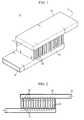
- FIG. 1 is a perspective view showing a conventional Z-type battery pack
- FIG. 2 is a sectional view taken along the line A-A' of FIG. 1 .
- the Z-type battery pack 10 includes a plurality of battery cells 20 connected in series and cooling channels 30, 40 coupled to the battery cells 20.
- the cooling channels 30, 40 include a first cooling channel 30 coupled to a top of the battery cell 20 and a second cooling channel 40 coupled to a bottom of the battery cell 20.
- One side 32 of the first cooling channel 30 is open such that a cooling gas may be introduced therein.
- a plurality of slits 34 are formed in a lower surface of the first cooling channel 30, not coupled with the battery cells 20, such that the introduced cooling gas may be discharged toward the battery cells 20.
- a plurality of slits 44 are formed in an upper surface of the second cooling channel 40, not coupled with the battery cells 20, such that the cooling gas discharged from the first cooling channel 30 is introduced. Also, one side 42 of the second cooling channel 40 is open such that the cooling gas introduced through the slits 44 may be discharged to the outside.
- the cooling gas introduced through the side 32 is discharged to the outside while passing through the slits 34, the spaces between the battery cells 20, and the slits 44 in order. In this procedure, the cooling gas absorbs heat from the battery cells 20, so the battery cells 20 may be cooled.
- FIG. 3 is a graph showing temperature distribution of the battery cells 20 included in the battery pack 10.
- a horizontal axis represents the number of each battery cell 20, and a vertical axis represents temperature of each battery cell 20.
- the number of battery cell 20 is set to increase in a right direction based on FIG. 2 .
- the results shown in FIG. 3 are derived under the condition that loads of 40A are applied to a battery pack 10 including 44 battery cells 20 with an ambient air of 30°C.
- the present invention is designed to solve the problems of the prior art, and therefore it is an object of the present invention to provide a Z-type battery pack for an electric vehicle, which may decrease a maximum temperature of battery cells and reduce temperature variation among battery cells in comparison to conventional cases.
- the present invention provides a Z-type battery pack for an electric vehicle, in which an introduction direction of a cooling gas is identical to a discharging direction thereof, the Z-type battery pack including: a plurality of battery cells arranged as being connected in series; a first cooling channel coupled to one ends of the battery cells to control a flow of a cooling gas such that a cooling gas introduced from the outside is discharged between the battery cells; a second cooling channel coupled to the other ends of the battery cells to control a flow of the cooling gas such that the cooling gas passing between the battery cells is discharged to the outside; and a flux control plate located in the second cooling channel to uniformly keep a flux of the cooling gas passing between the battery cells.
- the flux control plate includes a blocking plate extending from an upper surface of the second cooling channel toward a lower surface thereof and preventing the cooling gas passing between the battery cells from being directly discharged to the outside; and a flow guide plate extending from one end of the blocking plate along a length direction of the second cooling channel, the flow guide plate guiding a flow of the cooing gas such that the cooling gas passing between the battery cells is moved in a direction opposite to the introduction direction of the cooling gas and then discharged to the outside.
- the flow guide plate has a length in the range from 70% to 95% of a distance between battery cells located at the outermost positions. If the length of the flow guide plate is shorter than the lower limit, the flux of cooling gas passing between the battery cells may not be kept uniformly. If the length of the flow guide plate is longer than the upper limit, an excessive load is applied to the motor supplying the cooling gas to the first cooling channel. If the length of the flow guide plate is over the lower limit, temperature variation of the battery cells may be kept to 5°C or less, so the life span of the battery pack may be elongated.
- the flow guide plate has a width identical to a width of the second cooling channel.
- the cooling gas passing between the battery cells cannot flow between the flow guide plate and the side of the second cooling channel, so the flux of cooling gas flowing between the battery cells may be more uniformly kept.
- a distance between the flow guide plate and the upper surface of the second cooling channel is identical to a distance between the flow guide plate and a lower surface of the second cooling channel.
- the flow guide plate is extended in parallel with a length direction of the second cooling channel.
- the flow guide plate may be extended with a slope such that the flow guide plate is closer to an upper or lower surface of the second cooling channel as approaching to an end thereof.
- the slope of the flow guide plate is preferably controlled by fixing a location of an end portion of the flow guide plate and then adjusting a length of the blocking plate.
- a flux of cooling gas passing through spaces between battery cells is kept uniformly, and accordingly a maximum temperature of the battery cells and temperature variation among the battery cells are greatly decreased in comparison to conventional cases, so the life span of the battery pack is extended very long and the possibility of explosion of the battery pack is eliminated.
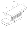
- FIG. 4 is a perspective view showing a Z-type battery pack for an electric vehicle according to a first embodiment of the present invention
- FIG. 5 is a sectional view taken along the line B-B' of Fig. 4
- FIG. 6 is a sectional view taken along the line C-C' of Fig. 4
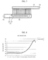
- FIG. 7 is a sectional view showing a Z-type battery pack for an electric vehicle according to a second embodiment of the present invention.
- the Z-type battery pack 100 includes a plurality of battery cells 110, a first cooling channel 130 coupled to one ends of the battery cells 110, a second cooling channel 150 coupled to the other ends of the battery cells 110, and a flux control plate 170 located in the second cooling channel 150.
- the plurality of battery cells 110 are arranged as being connected in series, and the battery cells 110 may be arranged in one row or multiple rows. Voltage charged to the battery cells 110 is used for driving an electric vehicle, and the battery cells 110 are charged again if the battery cells 110 are discharged. The battery cells 110 repeat charging and discharging as mentioned above, during which heat is generated from the battery cells 110.
- One side 132 of the first cooling channel 130 is open such that a cooling gas for cooling the battery cells is introduced from the outside. Also, a plurality of slits 134 are formed in a lower surface of the first cooling channel 130, not coupled with the battery cells 110, such that the introduced cooling gas may be discharged toward the battery cells 110. The cooling gas introduced through the side 132 is flowed into spaces between the battery cells 110 through the plurality of slits 134 to cool the battery cells 110.
- a plurality of slits 154 are formed in an upper surface of the second cooling channel 150, not coupled with the battery cells 110, such that the cooling gas passing through the spaces between the battery cells 110 are introduced thereto. Also, one side 152 of the second cooling channel 150 is open such that the cooling gas introduced through the slits 153 may be discharged to the outside. At this time, a discharging direction of the cooling gas is identical to a direction in which the cooling gas is introduced to the first cooling channel 130.
- the flux control plate 170 is located in the second cooling channel 150 to uniformly keep a flux of cooling gas passing between the battery cells 110.
- embodiments of the flux control plate 170 having the above function are explained in detail.
- the flux control plate 170 includes a blocking plate 172 and a flow guide plate 174.
- the blocking plate 172 prevents the cooling gas passing between the battery cells 110 from being directly discharged to the outside through the side 152.
- One end of the blocking plate 172 is attached to one side of the first cooling channel 130, and the blocking plate 172 is extended from one side of the first cooling channel 130 through the upper surface of the second cooling channel 150 to the inside of the second cooling channel 150.
- a width of the blocking plate 172 is preferably identical to a width W1 of the second cooling channel 150 such that the cooling gas is not directly discharged to the outside through the side 152.
- the flow guide plate 174 guides the flow of cooling gas such that the cooling gas passing between the battery cells 110 is moved in a direction opposite to an introduction direction of the cooling gas (namely, a direction in which the cooling gas is introduced to the first cooling channel 130) and then discharged to the outside through the side 152.
- the flow guide plate 174 is extended in parallel with a length direction of the second cooling channel 150 from one end of the blocking plate 172.
- the flow guide plate 174 has a width identical to the width W1 of the second cooling channel.
- the battery pack 100 includes the flux control plate 170 as mentioned above.
- the pressure difference between the first cooling channel 130 and the second cooling channel 150 is formed more uniformly in comparison to conventional cases, so a flux of cooling gas passing through the spaces formed between the battery cells 110 becomes very uniform in comparison to conventional cases regardless of the distance from the side 132.
- the maximum temperature of the battery cells 110 may be decreased rather than conventional cases, and temperature variation among the battery cells 110 may also be reduced rather than conventional cases.
- the uniformity of flux of the cooling gas passing between the battery cells 110 becomes better as a length L1 of the flow guide plate 174 is greater.
- a load applied to a motor (not shown) supplying the cooling gas is increased.
- the length L1 of the flow guide plate 174 should be set in consideration of the uniformity of flux of the cooling gas passing between the battery cells 110 and the load of a motor supplying the cooling gas.
- the length L1 of the flow guide plate 174 is preferably selected in the range from 70% to 95% of a length L2 between battery cells located at outermost positions. If the length L1 of the flow guide plate is shorter than the lower limit, the flux of cooling gas passing between the battery cells 110 may not be kept uniformly. If the length of the flow guide plate is longer than the upper limit, an excessive load is applied to the motor supplying the cooling gas to the first cooling channel. If the length L1 of the flow guide plate is over the lower limit, temperature variation of the battery cells 110 may be kept to 5°C or less, so the life span of the battery pack 100 may be elongated.
- the width of the flow guide plate 174 is preferably set identically to the width W1 of the second cooling channel, as explained above. However, if there is no serious difference in the flux of cooling gas, the width of the flow guide plate 174 may be set smaller than the width W1 of the second cooling channel.
- the load applied to the motor (not shown) supplying the cooling gas is increased.
- the uniformity of the flux of cooling gas passing between the battery cells 110 is deteriorated when the distance between the flow guide plate 174 and the upper surface of the second cooling channel 150 is longer or shorter than a distance between the flow guide plate 174 and a lower surface of the second cooling channel 150.
- the distance between the flow guide plate 174 and the upper surface of the second cooling channel 150 is preferably set identically to the distance between the flow guide plate 174 and the lower surface of the second cooling channel 150.
- the blocking plate 172 is configured to pass through the upper surface of the second cooling channel 150.
- the blocking plate 172 may be configured as being positioned only in the second cooling channel, as shown in FIG. 7 .
- the flow guide plate 174 is configured in parallel with the length direction of the second cooling channel 150.
- the flow guide plate 174 may be configured with a slope such that the flow guide plate 174 becomes closer to the upper or lower surface of the second cooling channel 150 as approaching its end.
- the slope of the flow guide plate 174 may be controlled by fixing a location of an end portion of the flow guide plate 174 and then adjusting a length of the blocking plate 172. As a distance between the end of the flow guide plate 174 and the upper surface of the second cooling channel 150 is shorter, the load applied to the motor supplying the cooling gas is increased.
- the slope of the flow guide plate 174 is controlled as mentioned above, the uniformity of the flux of cooling gas passing between the battery cells 110 is ensured, and at the same time, the load applied to the motor supplying the cooling gas may be kept uniformly.
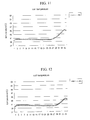
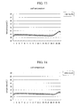
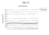
- FIGs. 8 to 15 are graphs representing temperature distribution of the battery cells 110 included in the battery pack 100.
- a horizontal axis represents the number of each battery cell 110
- a vertical axis represents temperature of each battery cell 110.
- the number of each battery cell 110 is increased in a right direction based on FIG. 5 .
- the width of the flow guide plate 174 is set identically to the width W1 of the second cooling channel.
- the length L1 of the flow guide plate 174 is respectively set as 50.0%, 60.0%, 66.3%, 71.8%, 77.3%, 82.8%, 88.3% and 93.8% of the length L2 between the battery cells located at the outermost locations.
- the flow guide plate 174 is formed in parallel with the length direction of the second cooling channel 150, and the flow guide plate 174 is installed at a center between the upper and lower surfaces of the second cooling channel 150.
- the results shown in FIGs. 8 to 15 are derived under the condition that loads of 40A are applied to the battery pack 100 including 35 battery cells 110 with an ambient air of 35°C.
- temperature deviation of the battery cells 110 is decreased as the length L1 of the flow guide plate 174 is longer, and it would be understood that a ratio of L1/L2 is 70% or above, the temperature variation becomes 5°C or less. If the temperature variation is 5°C or below, the life span of the battery pack 100 may be elongated.
Landscapes
- Engineering & Computer Science (AREA)
- Chemical & Material Sciences (AREA)
- Chemical Kinetics & Catalysis (AREA)
- Electrochemistry (AREA)
- General Chemical & Material Sciences (AREA)
- Manufacturing & Machinery (AREA)
- Power Engineering (AREA)
- Mechanical Engineering (AREA)
- Sustainable Development (AREA)
- Sustainable Energy (AREA)
- Life Sciences & Earth Sciences (AREA)
- Transportation (AREA)
- Physics & Mathematics (AREA)
- Aviation & Aerospace Engineering (AREA)
- Algebra (AREA)
- General Physics & Mathematics (AREA)
- Mathematical Analysis (AREA)
- Mathematical Optimization (AREA)
- Pure & Applied Mathematics (AREA)
- Secondary Cells (AREA)
- Battery Mounting, Suspending (AREA)
Applications Claiming Priority (3)
| Application Number | Priority Date | Filing Date | Title |
|---|---|---|---|
| KR20080018411 | 2008-02-28 | ||
| KR1020090016433A KR101091211B1 (ko) | 2008-02-28 | 2009-02-26 | 전기자동차용 제트 타입 배터리팩 |
| PCT/KR2009/000961 WO2009108013A2 (ko) | 2008-02-28 | 2009-02-27 | 전기자동차용 제트 타입 배터리팩 |
Publications (3)
| Publication Number | Publication Date |
|---|---|
| EP2246930A2 true EP2246930A2 (de) | 2010-11-03 |
| EP2246930A4 EP2246930A4 (de) | 2013-03-20 |
| EP2246930B1 EP2246930B1 (de) | 2016-11-23 |
Family
ID=41016604
Family Applications (1)
| Application Number | Title | Priority Date | Filing Date |
|---|---|---|---|
| EP09714095.8A Active EP2246930B1 (de) | 2008-02-28 | 2009-02-27 | Batteriepack für ein elektrisches fahrzeug |
Country Status (6)
| Country | Link |
|---|---|
| US (1) | US8435661B2 (de) |
| EP (1) | EP2246930B1 (de) |
| JP (1) | JP5483602B2 (de) |
| KR (1) | KR101091211B1 (de) |
| CN (1) | CN101960663B (de) |
| WO (1) | WO2009108013A2 (de) |
Cited By (4)
| Publication number | Priority date | Publication date | Assignee | Title |
|---|---|---|---|---|
| DE102010052506A1 (de) * | 2010-11-26 | 2012-05-31 | Ads-Tec Gmbh | Akkupack |
| EP2617081A4 (de) * | 2011-01-24 | 2013-10-23 | Guoan Feng | Kühlvorrichtung für eine batteriepackung |
| EP2590255A4 (de) * | 2010-04-13 | 2015-07-15 | Lg Chemical Ltd | Batteriepackgehäuse mit neuartiger struktur |
| EP2945216A4 (de) * | 2013-01-11 | 2016-11-02 | Futaba Ind Co Ltd | Montierte batteriehaltevorrichtung, montiertes batteriehalteelement und batterie |
Families Citing this family (22)
| Publication number | Priority date | Publication date | Assignee | Title |
|---|---|---|---|---|
| CN101894985B (zh) * | 2010-06-30 | 2014-12-31 | 中国电力科学研究院 | 一种电池组冷却结构 |
| DE102011015337A1 (de) * | 2011-03-28 | 2012-10-04 | Rehau Ag + Co. | Batterietemperiersystem, Kraftfahrzeug mit einem Batterietemperiersystem sowie Verfahren zum Betreiben eines Batterietemperiersystems |
| KR101658027B1 (ko) | 2011-11-22 | 2016-09-21 | 삼성에스디아이 주식회사 | 배터리 팩 |
| KR20130064503A (ko) * | 2011-12-08 | 2013-06-18 | 에스케이이노베이션 주식회사 | 셀조립체 형태의 배터리 냉각장치 |
| CN102637885A (zh) * | 2012-04-27 | 2012-08-15 | 中国东方电气集团有限公司 | 冷却系统及燃料电池堆 |
| KR101669118B1 (ko) | 2013-01-03 | 2016-10-25 | 삼성에스디아이 주식회사 | 배터리 팩 |
| JP6099194B2 (ja) * | 2013-01-31 | 2017-03-22 | 本田技研工業株式会社 | 蓄電装置の冷却構造 |
| CN103413989B (zh) * | 2013-07-25 | 2016-11-09 | 天津市松正电动汽车技术股份有限公司 | 一种电池散热系统 |
| JP6382067B2 (ja) * | 2014-10-27 | 2018-08-29 | 株式会社協豊製作所 | 電池パック |
| DE102015108611A1 (de) * | 2015-06-01 | 2016-12-01 | Dr. Ing. H.C. F. Porsche Aktiengesellschaft | Fahrzeugkomponente |
| KR20180058088A (ko) * | 2016-11-23 | 2018-05-31 | 공주대학교 산학협력단 | 냉각특성이 향상된 전기자동차용 배터리 모듈 |
| US20180287225A1 (en) * | 2017-03-28 | 2018-10-04 | Ford Global Technologies, Llc | System for closed loop direct cooling of a sealed high voltage traction battery pack |
| JP2019008974A (ja) * | 2017-06-23 | 2019-01-17 | 日野自動車株式会社 | 電装品の冷却構造 |
| CN107623153A (zh) * | 2017-08-17 | 2018-01-23 | 天津瑷睿卡仕福测控技术有限公司 | 一种动力电池风冷模组 |
| CN108091961B (zh) * | 2017-12-12 | 2021-09-17 | 桑顿新能源科技(长沙)有限公司 | 一种电池用引流均温液冷板 |
| FR3077430B1 (fr) | 2018-01-29 | 2020-02-14 | Commissariat A L'energie Atomique Et Aux Energies Alternatives | Module d'accumulateurs electriques et batterie comprenant plusieurs modules |
| FR3077431B1 (fr) * | 2018-01-29 | 2020-07-31 | Commissariat Energie Atomique | Module d'accumulateurs electriques et batterie comprenant plusieurs modules |
| CN111525068B (zh) * | 2020-05-06 | 2022-05-17 | 重庆广播电视大学重庆工商职业学院 | 新能源汽车高效散热电池组 |
| KR102857913B1 (ko) * | 2021-06-17 | 2025-09-09 | 주식회사 엘지에너지솔루션 | 개선된 벤팅 성능을 갖는 배터리 모듈 |
| CN113782910B (zh) * | 2021-08-27 | 2023-09-08 | 中国第一汽车股份有限公司 | 一种动力电池包的热流泄放装置、方法、动力电池包和车辆 |
| CN217423575U (zh) * | 2022-03-14 | 2022-09-13 | 阳光电源股份有限公司 | 导流格栅、空调器和储能装置 |
| SE546145C2 (en) | 2023-07-26 | 2024-06-11 | Ab Solask Energi | Battery module and battery cabinet |
Family Cites Families (10)
| Publication number | Priority date | Publication date | Assignee | Title |
|---|---|---|---|---|
| JP4423695B2 (ja) * | 1999-02-23 | 2010-03-03 | トヨタ自動車株式会社 | 集電池 |
| US6641947B1 (en) * | 1999-09-21 | 2003-11-04 | The Gillette Company | Air manager system for metal air battery |
| JP2002033137A (ja) * | 2000-07-17 | 2002-01-31 | Matsushita Electric Ind Co Ltd | 電池電源装置 |
| KR100581251B1 (ko) * | 2003-10-30 | 2006-05-22 | 현대자동차주식회사 | 배터리의 냉각장치 및 방법 |
| KR20050070727A (ko) * | 2003-12-30 | 2005-07-07 | 현대자동차주식회사 | 전기자동차의 배터리 냉각장치 |
| KR100853621B1 (ko) * | 2004-10-26 | 2008-08-25 | 주식회사 엘지화학 | 전지팩의 냉각 시스템 |
| KR100658717B1 (ko) * | 2004-10-28 | 2006-12-15 | 삼성에스디아이 주식회사 | 전지 모듈 및 전지 모듈용 냉각장치 |
| KR100684768B1 (ko) * | 2005-07-29 | 2007-02-20 | 삼성에스디아이 주식회사 | 이차 전지 모듈 |
| KR101029021B1 (ko) | 2005-12-02 | 2011-04-14 | 주식회사 엘지화학 | 높은 냉각 효율성의 전지모듈 |
| JP2007227030A (ja) * | 2006-02-21 | 2007-09-06 | Toyota Motor Corp | 電池パック |
-
2009
- 2009-02-26 KR KR1020090016433A patent/KR101091211B1/ko active Active
- 2009-02-27 WO PCT/KR2009/000961 patent/WO2009108013A2/ko not_active Ceased
- 2009-02-27 CN CN2009801067330A patent/CN101960663B/zh active Active
- 2009-02-27 US US12/919,683 patent/US8435661B2/en active Active
- 2009-02-27 EP EP09714095.8A patent/EP2246930B1/de active Active
- 2009-02-27 JP JP2010548622A patent/JP5483602B2/ja active Active
Cited By (6)
| Publication number | Priority date | Publication date | Assignee | Title |
|---|---|---|---|---|
| EP2590255A4 (de) * | 2010-04-13 | 2015-07-15 | Lg Chemical Ltd | Batteriepackgehäuse mit neuartiger struktur |
| DE102010052506A1 (de) * | 2010-11-26 | 2012-05-31 | Ads-Tec Gmbh | Akkupack |
| DE102010052506B4 (de) | 2010-11-26 | 2024-08-14 | Ads-tec Energy GmbH | Akkupack |
| EP2617081A4 (de) * | 2011-01-24 | 2013-10-23 | Guoan Feng | Kühlvorrichtung für eine batteriepackung |
| US8974943B2 (en) | 2011-01-24 | 2015-03-10 | Guoan Feng | Power battery pack cooling apparatus |
| EP2945216A4 (de) * | 2013-01-11 | 2016-11-02 | Futaba Ind Co Ltd | Montierte batteriehaltevorrichtung, montiertes batteriehalteelement und batterie |
Also Published As
| Publication number | Publication date |
|---|---|
| EP2246930A4 (de) | 2013-03-20 |
| US20110008657A1 (en) | 2011-01-13 |
| KR101091211B1 (ko) | 2011-12-07 |
| WO2009108013A3 (ko) | 2009-11-26 |
| JP5483602B2 (ja) | 2014-05-07 |
| CN101960663A (zh) | 2011-01-26 |
| KR20090093852A (ko) | 2009-09-02 |
| EP2246930B1 (de) | 2016-11-23 |
| JP2011515798A (ja) | 2011-05-19 |
| WO2009108013A2 (ko) | 2009-09-03 |
| CN101960663B (zh) | 2013-07-17 |
| US8435661B2 (en) | 2013-05-07 |
Similar Documents
| Publication | Publication Date | Title |
|---|---|---|
| US8435661B2 (en) | Z-type battery pack for vehicle | |
| US9478778B2 (en) | Middle or large-sized battery pack case providing improved distribution uniformity of coolant flux | |
| US8420245B2 (en) | Middle or large-sized battery pack case providing improved distribution uniformity of coolant flux | |
| US8211564B2 (en) | Middle or large-sized battery pack case providing improved distribution uniformity in coolant flux | |
| US9614206B2 (en) | Middle or large-sized battery pack case providing improved distribution uniformity in coolant flux | |
| CN101604735B (zh) | 具有改进的冷却剂流量分布均一性的中型或大型电池组盒 | |
| JP4659699B2 (ja) | 電池モジュール | |
| JP5384635B2 (ja) | 優れた冷却効率の中型又は大型のバッテリーパックケース | |
| JP2011520235A (ja) | 電気自動車用uタイプバッテリーパック | |
| CN101882691A (zh) | 电池系统 | |
| US20130344358A1 (en) | Battery compartment for a vehicle | |
| US12136715B2 (en) | Battery pack housing | |
| US9825342B2 (en) | Cooling conduit |
Legal Events
| Date | Code | Title | Description |
|---|---|---|---|
| PUAI | Public reference made under article 153(3) epc to a published international application that has entered the european phase |
Free format text: ORIGINAL CODE: 0009012 |
|
| 17P | Request for examination filed |
Effective date: 20100727 |
|
| AK | Designated contracting states |
Kind code of ref document: A2 Designated state(s): AT BE BG CH CY CZ DE DK EE ES FI FR GB GR HR HU IE IS IT LI LT LU LV MC MK MT NL NO PL PT RO SE SI SK TR |
|
| AX | Request for extension of the european patent |
Extension state: AL BA RS |
|
| RIN1 | Information on inventor provided before grant (corrected) |
Inventor name: KANG, DAL-MO Inventor name: IM, YE-HOON Inventor name: CHUNG, CHAE-HO Inventor name: YOON, JONG-MOON |
|
| RIN1 | Information on inventor provided before grant (corrected) |
Inventor name: KANG, DAL-MO Inventor name: CHUNG, CHAE-HO Inventor name: IM, YE-HOON Inventor name: YOON, JONG-MOON |
|
| RIN1 | Information on inventor provided before grant (corrected) |
Inventor name: KANG, DAL-MO Inventor name: CHUNG, CHAE-HO Inventor name: IM, YE-HOON Inventor name: YOON, JONG-MOON |
|
| DAX | Request for extension of the european patent (deleted) | ||
| A4 | Supplementary search report drawn up and despatched |
Effective date: 20130219 |
|
| RIC1 | Information provided on ipc code assigned before grant |
Ipc: B60L 11/18 20060101ALI20130213BHEP Ipc: H01M 10/50 20060101AFI20130213BHEP |
|
| 17Q | First examination report despatched |
Effective date: 20150515 |
|
| REG | Reference to a national code |
Ref country code: DE Ref legal event code: R079 Ref document number: 602009042581 Country of ref document: DE Free format text: PREVIOUS MAIN CLASS: H01M0010500000 Ipc: H01M0010613000 |
|
| GRAP | Despatch of communication of intention to grant a patent |
Free format text: ORIGINAL CODE: EPIDOSNIGR1 |
|
| RIC1 | Information provided on ipc code assigned before grant |
Ipc: H01M 10/6566 20140101ALI20160729BHEP Ipc: H01M 10/613 20140101AFI20160729BHEP Ipc: H01M 10/6563 20140101ALI20160729BHEP |
|
| INTG | Intention to grant announced |
Effective date: 20160831 |
|
| GRAS | Grant fee paid |
Free format text: ORIGINAL CODE: EPIDOSNIGR3 |
|
| GRAA | (expected) grant |
Free format text: ORIGINAL CODE: 0009210 |
|
| AK | Designated contracting states |
Kind code of ref document: B1 Designated state(s): AT BE BG CH CY CZ DE DK EE ES FI FR GB GR HR HU IE IS IT LI LT LU LV MC MK MT NL NO PL PT RO SE SI SK TR |
|
| REG | Reference to a national code |
Ref country code: GB Ref legal event code: FG4D |
|
| REG | Reference to a national code |
Ref country code: CH Ref legal event code: EP |
|
| REG | Reference to a national code |
Ref country code: IE Ref legal event code: FG4D |
|
| REG | Reference to a national code |
Ref country code: AT Ref legal event code: REF Ref document number: 848642 Country of ref document: AT Kind code of ref document: T Effective date: 20161215 |
|
| REG | Reference to a national code |
Ref country code: DE Ref legal event code: R096 Ref document number: 602009042581 Country of ref document: DE |
|
| REG | Reference to a national code |
Ref country code: FR Ref legal event code: PLFP Year of fee payment: 9 |
|
| PG25 | Lapsed in a contracting state [announced via postgrant information from national office to epo] |
Ref country code: LV Free format text: LAPSE BECAUSE OF FAILURE TO SUBMIT A TRANSLATION OF THE DESCRIPTION OR TO PAY THE FEE WITHIN THE PRESCRIBED TIME-LIMIT Effective date: 20161123 |
|
| REG | Reference to a national code |
Ref country code: LT Ref legal event code: MG4D |
|
| REG | Reference to a national code |
Ref country code: NL Ref legal event code: MP Effective date: 20161123 |
|
| REG | Reference to a national code |
Ref country code: AT Ref legal event code: MK05 Ref document number: 848642 Country of ref document: AT Kind code of ref document: T Effective date: 20161123 |
|
| PG25 | Lapsed in a contracting state [announced via postgrant information from national office to epo] |
Ref country code: NL Free format text: LAPSE BECAUSE OF FAILURE TO SUBMIT A TRANSLATION OF THE DESCRIPTION OR TO PAY THE FEE WITHIN THE PRESCRIBED TIME-LIMIT Effective date: 20161123 Ref country code: NO Free format text: LAPSE BECAUSE OF FAILURE TO SUBMIT A TRANSLATION OF THE DESCRIPTION OR TO PAY THE FEE WITHIN THE PRESCRIBED TIME-LIMIT Effective date: 20170223 Ref country code: SE Free format text: LAPSE BECAUSE OF FAILURE TO SUBMIT A TRANSLATION OF THE DESCRIPTION OR TO PAY THE FEE WITHIN THE PRESCRIBED TIME-LIMIT Effective date: 20161123 Ref country code: LT Free format text: LAPSE BECAUSE OF FAILURE TO SUBMIT A TRANSLATION OF THE DESCRIPTION OR TO PAY THE FEE WITHIN THE PRESCRIBED TIME-LIMIT Effective date: 20161123 Ref country code: GR Free format text: LAPSE BECAUSE OF FAILURE TO SUBMIT A TRANSLATION OF THE DESCRIPTION OR TO PAY THE FEE WITHIN THE PRESCRIBED TIME-LIMIT Effective date: 20170224 |
|
| PG25 | Lapsed in a contracting state [announced via postgrant information from national office to epo] |
Ref country code: AT Free format text: LAPSE BECAUSE OF FAILURE TO SUBMIT A TRANSLATION OF THE DESCRIPTION OR TO PAY THE FEE WITHIN THE PRESCRIBED TIME-LIMIT Effective date: 20161123 Ref country code: BE Free format text: LAPSE BECAUSE OF NON-PAYMENT OF DUE FEES Effective date: 20170228 Ref country code: PL Free format text: LAPSE BECAUSE OF FAILURE TO SUBMIT A TRANSLATION OF THE DESCRIPTION OR TO PAY THE FEE WITHIN THE PRESCRIBED TIME-LIMIT Effective date: 20161123 Ref country code: FI Free format text: LAPSE BECAUSE OF FAILURE TO SUBMIT A TRANSLATION OF THE DESCRIPTION OR TO PAY THE FEE WITHIN THE PRESCRIBED TIME-LIMIT Effective date: 20161123 Ref country code: ES Free format text: LAPSE BECAUSE OF FAILURE TO SUBMIT A TRANSLATION OF THE DESCRIPTION OR TO PAY THE FEE WITHIN THE PRESCRIBED TIME-LIMIT Effective date: 20161123 Ref country code: HR Free format text: LAPSE BECAUSE OF FAILURE TO SUBMIT A TRANSLATION OF THE DESCRIPTION OR TO PAY THE FEE WITHIN THE PRESCRIBED TIME-LIMIT Effective date: 20161123 Ref country code: PT Free format text: LAPSE BECAUSE OF FAILURE TO SUBMIT A TRANSLATION OF THE DESCRIPTION OR TO PAY THE FEE WITHIN THE PRESCRIBED TIME-LIMIT Effective date: 20170323 |
|
| PG25 | Lapsed in a contracting state [announced via postgrant information from national office to epo] |
Ref country code: EE Free format text: LAPSE BECAUSE OF FAILURE TO SUBMIT A TRANSLATION OF THE DESCRIPTION OR TO PAY THE FEE WITHIN THE PRESCRIBED TIME-LIMIT Effective date: 20161123 Ref country code: DK Free format text: LAPSE BECAUSE OF FAILURE TO SUBMIT A TRANSLATION OF THE DESCRIPTION OR TO PAY THE FEE WITHIN THE PRESCRIBED TIME-LIMIT Effective date: 20161123 Ref country code: CZ Free format text: LAPSE BECAUSE OF FAILURE TO SUBMIT A TRANSLATION OF THE DESCRIPTION OR TO PAY THE FEE WITHIN THE PRESCRIBED TIME-LIMIT Effective date: 20161123 Ref country code: SK Free format text: LAPSE BECAUSE OF FAILURE TO SUBMIT A TRANSLATION OF THE DESCRIPTION OR TO PAY THE FEE WITHIN THE PRESCRIBED TIME-LIMIT Effective date: 20161123 Ref country code: RO Free format text: LAPSE BECAUSE OF FAILURE TO SUBMIT A TRANSLATION OF THE DESCRIPTION OR TO PAY THE FEE WITHIN THE PRESCRIBED TIME-LIMIT Effective date: 20161123 |
|
| REG | Reference to a national code |
Ref country code: DE Ref legal event code: R097 Ref document number: 602009042581 Country of ref document: DE |
|
| PG25 | Lapsed in a contracting state [announced via postgrant information from national office to epo] |
Ref country code: IT Free format text: LAPSE BECAUSE OF FAILURE TO SUBMIT A TRANSLATION OF THE DESCRIPTION OR TO PAY THE FEE WITHIN THE PRESCRIBED TIME-LIMIT Effective date: 20161123 Ref country code: BG Free format text: LAPSE BECAUSE OF FAILURE TO SUBMIT A TRANSLATION OF THE DESCRIPTION OR TO PAY THE FEE WITHIN THE PRESCRIBED TIME-LIMIT Effective date: 20170223 Ref country code: BE Free format text: LAPSE BECAUSE OF FAILURE TO SUBMIT A TRANSLATION OF THE DESCRIPTION OR TO PAY THE FEE WITHIN THE PRESCRIBED TIME-LIMIT Effective date: 20161123 |
|
| PG25 | Lapsed in a contracting state [announced via postgrant information from national office to epo] |
Ref country code: MC Free format text: LAPSE BECAUSE OF FAILURE TO SUBMIT A TRANSLATION OF THE DESCRIPTION OR TO PAY THE FEE WITHIN THE PRESCRIBED TIME-LIMIT Effective date: 20161123 |
|
| PLBE | No opposition filed within time limit |
Free format text: ORIGINAL CODE: 0009261 |
|
| REG | Reference to a national code |
Ref country code: CH Ref legal event code: PL |
|
| STAA | Information on the status of an ep patent application or granted ep patent |
Free format text: STATUS: NO OPPOSITION FILED WITHIN TIME LIMIT |
|
| PG25 | Lapsed in a contracting state [announced via postgrant information from national office to epo] |
Ref country code: LI Free format text: LAPSE BECAUSE OF NON-PAYMENT OF DUE FEES Effective date: 20170228 Ref country code: CH Free format text: LAPSE BECAUSE OF NON-PAYMENT OF DUE FEES Effective date: 20170228 |
|
| 26N | No opposition filed |
Effective date: 20170824 |
|
| REG | Reference to a national code |
Ref country code: IE Ref legal event code: MM4A |
|
| PG25 | Lapsed in a contracting state [announced via postgrant information from national office to epo] |
Ref country code: SI Free format text: LAPSE BECAUSE OF FAILURE TO SUBMIT A TRANSLATION OF THE DESCRIPTION OR TO PAY THE FEE WITHIN THE PRESCRIBED TIME-LIMIT Effective date: 20161123 |
|
| PG25 | Lapsed in a contracting state [announced via postgrant information from national office to epo] |
Ref country code: LU Free format text: LAPSE BECAUSE OF NON-PAYMENT OF DUE FEES Effective date: 20170227 |
|
| REG | Reference to a national code |
Ref country code: FR Ref legal event code: PLFP Year of fee payment: 10 |
|
| PG25 | Lapsed in a contracting state [announced via postgrant information from national office to epo] |
Ref country code: IE Free format text: LAPSE BECAUSE OF NON-PAYMENT OF DUE FEES Effective date: 20170227 |
|
| PG25 | Lapsed in a contracting state [announced via postgrant information from national office to epo] |
Ref country code: MT Free format text: LAPSE BECAUSE OF NON-PAYMENT OF DUE FEES Effective date: 20170227 |
|
| PG25 | Lapsed in a contracting state [announced via postgrant information from national office to epo] |
Ref country code: HU Free format text: LAPSE BECAUSE OF FAILURE TO SUBMIT A TRANSLATION OF THE DESCRIPTION OR TO PAY THE FEE WITHIN THE PRESCRIBED TIME-LIMIT; INVALID AB INITIO Effective date: 20090227 |
|
| PG25 | Lapsed in a contracting state [announced via postgrant information from national office to epo] |
Ref country code: CY Free format text: LAPSE BECAUSE OF NON-PAYMENT OF DUE FEES Effective date: 20161123 |
|
| PG25 | Lapsed in a contracting state [announced via postgrant information from national office to epo] |
Ref country code: MK Free format text: LAPSE BECAUSE OF FAILURE TO SUBMIT A TRANSLATION OF THE DESCRIPTION OR TO PAY THE FEE WITHIN THE PRESCRIBED TIME-LIMIT Effective date: 20161123 |
|
| PG25 | Lapsed in a contracting state [announced via postgrant information from national office to epo] |
Ref country code: TR Free format text: LAPSE BECAUSE OF FAILURE TO SUBMIT A TRANSLATION OF THE DESCRIPTION OR TO PAY THE FEE WITHIN THE PRESCRIBED TIME-LIMIT Effective date: 20161123 |
|
| PG25 | Lapsed in a contracting state [announced via postgrant information from national office to epo] |
Ref country code: IS Free format text: LAPSE BECAUSE OF FAILURE TO SUBMIT A TRANSLATION OF THE DESCRIPTION OR TO PAY THE FEE WITHIN THE PRESCRIBED TIME-LIMIT Effective date: 20170323 |
|
| REG | Reference to a national code |
Ref country code: DE Ref legal event code: R081 Ref document number: 602009042581 Country of ref document: DE Owner name: LG ENERGY SOLUTION LTD., KR Free format text: FORMER OWNER: LG CHEM. LTD., SEOUL, KR Ref country code: DE Ref legal event code: R081 Ref document number: 602009042581 Country of ref document: DE Owner name: LG ENERGY SOLUTION, LTD., KR Free format text: FORMER OWNER: LG CHEM. LTD., SEOUL, KR |
|
| P01 | Opt-out of the competence of the unified patent court (upc) registered |
Effective date: 20230323 |
|
| REG | Reference to a national code |
Ref country code: GB Ref legal event code: 732E Free format text: REGISTERED BETWEEN 20230824 AND 20230831 |
|
| REG | Reference to a national code |
Ref country code: DE Ref legal event code: R081 Ref document number: 602009042581 Country of ref document: DE Owner name: LG ENERGY SOLUTION, LTD., KR Free format text: FORMER OWNER: LG ENERGY SOLUTION LTD., SEOUL, KR |
|
| PGFP | Annual fee paid to national office [announced via postgrant information from national office to epo] |
Ref country code: GB Payment date: 20260122 Year of fee payment: 18 |
|
| PGFP | Annual fee paid to national office [announced via postgrant information from national office to epo] |
Ref country code: DE Payment date: 20260120 Year of fee payment: 18 |
|
| PGFP | Annual fee paid to national office [announced via postgrant information from national office to epo] |
Ref country code: FR Payment date: 20260121 Year of fee payment: 18 |