EP2244894B1 - Aufhängungssystem für fahrzeug - Google Patents
Aufhängungssystem für fahrzeug Download PDFInfo
- Publication number
- EP2244894B1 EP2244894B1 EP09715426A EP09715426A EP2244894B1 EP 2244894 B1 EP2244894 B1 EP 2244894B1 EP 09715426 A EP09715426 A EP 09715426A EP 09715426 A EP09715426 A EP 09715426A EP 2244894 B1 EP2244894 B1 EP 2244894B1
- Authority
- EP
- European Patent Office
- Prior art keywords
- force
- damping
- sprung
- displacement
- damper
- Prior art date
- Legal status (The legal status is an assumption and is not a legal conclusion. Google has not performed a legal analysis and makes no representation as to the accuracy of the status listed.)
- Not-in-force
Links
- 239000000725 suspension Substances 0.000 title claims description 108
- 238000013016 damping Methods 0.000 claims description 230
- 238000006073 displacement reaction Methods 0.000 claims description 124
- 230000000452 restraining effect Effects 0.000 claims description 75
- 230000001603 reducing effect Effects 0.000 claims description 31
- 230000008859 change Effects 0.000 claims description 18
- 230000033001 locomotion Effects 0.000 claims description 15
- 230000001419 dependent effect Effects 0.000 claims description 14
- 239000003638 chemical reducing agent Substances 0.000 claims description 13
- 230000001133 acceleration Effects 0.000 description 45
- 230000002829 reductive effect Effects 0.000 description 22
- 239000012530 fluid Substances 0.000 description 17
- 230000014509 gene expression Effects 0.000 description 13
- 238000010276 construction Methods 0.000 description 12
- 238000004891 communication Methods 0.000 description 11
- 238000000034 method Methods 0.000 description 10
- 230000009467 reduction Effects 0.000 description 10
- 230000006870 function Effects 0.000 description 7
- 230000007246 mechanism Effects 0.000 description 7
- 230000002401 inhibitory effect Effects 0.000 description 4
- 230000004044 response Effects 0.000 description 4
- 230000005540 biological transmission Effects 0.000 description 3
- 230000002093 peripheral effect Effects 0.000 description 3
- 239000006096 absorbing agent Substances 0.000 description 2
- 238000006243 chemical reaction Methods 0.000 description 2
- 230000010485 coping Effects 0.000 description 2
- 238000010586 diagram Methods 0.000 description 2
- 238000001914 filtration Methods 0.000 description 2
- 230000006872 improvement Effects 0.000 description 2
- 230000008569 process Effects 0.000 description 2
- 230000035939 shock Effects 0.000 description 2
- XUIMIQQOPSSXEZ-UHFFFAOYSA-N Silicon Chemical compound [Si] XUIMIQQOPSSXEZ-UHFFFAOYSA-N 0.000 description 1
- 230000004913 activation Effects 0.000 description 1
- 230000008901 benefit Effects 0.000 description 1
- 230000006835 compression Effects 0.000 description 1
- 238000007906 compression Methods 0.000 description 1
- 230000001747 exhibiting effect Effects 0.000 description 1
- 230000000670 limiting effect Effects 0.000 description 1
- 230000004048 modification Effects 0.000 description 1
- 238000012986 modification Methods 0.000 description 1
- 239000003921 oil Substances 0.000 description 1
- 229910052710 silicon Inorganic materials 0.000 description 1
- 239000010703 silicon Substances 0.000 description 1
Images


Classifications
-
- B—PERFORMING OPERATIONS; TRANSPORTING
- B60—VEHICLES IN GENERAL
- B60G—VEHICLE SUSPENSION ARRANGEMENTS
- B60G17/00—Resilient suspensions having means for adjusting the spring or vibration-damper characteristics, for regulating the distance between a supporting surface and a sprung part of vehicle or for locking suspension during use to meet varying vehicular or surface conditions, e.g. due to speed or load
- B60G17/06—Characteristics of dampers, e.g. mechanical dampers
- B60G17/08—Characteristics of fluid dampers
-
- B—PERFORMING OPERATIONS; TRANSPORTING
- B60—VEHICLES IN GENERAL
- B60G—VEHICLE SUSPENSION ARRANGEMENTS
- B60G17/00—Resilient suspensions having means for adjusting the spring or vibration-damper characteristics, for regulating the distance between a supporting surface and a sprung part of vehicle or for locking suspension during use to meet varying vehicular or surface conditions, e.g. due to speed or load
- B60G17/015—Resilient suspensions having means for adjusting the spring or vibration-damper characteristics, for regulating the distance between a supporting surface and a sprung part of vehicle or for locking suspension during use to meet varying vehicular or surface conditions, e.g. due to speed or load the regulating means comprising electric or electronic elements
- B60G17/0152—Resilient suspensions having means for adjusting the spring or vibration-damper characteristics, for regulating the distance between a supporting surface and a sprung part of vehicle or for locking suspension during use to meet varying vehicular or surface conditions, e.g. due to speed or load the regulating means comprising electric or electronic elements characterised by the action on a particular type of suspension unit
- B60G17/0157—Resilient suspensions having means for adjusting the spring or vibration-damper characteristics, for regulating the distance between a supporting surface and a sprung part of vehicle or for locking suspension during use to meet varying vehicular or surface conditions, e.g. due to speed or load the regulating means comprising electric or electronic elements characterised by the action on a particular type of suspension unit non-fluid unit, e.g. electric motor
-
- B—PERFORMING OPERATIONS; TRANSPORTING
- B60—VEHICLES IN GENERAL
- B60G—VEHICLE SUSPENSION ARRANGEMENTS
- B60G17/00—Resilient suspensions having means for adjusting the spring or vibration-damper characteristics, for regulating the distance between a supporting surface and a sprung part of vehicle or for locking suspension during use to meet varying vehicular or surface conditions, e.g. due to speed or load
- B60G17/015—Resilient suspensions having means for adjusting the spring or vibration-damper characteristics, for regulating the distance between a supporting surface and a sprung part of vehicle or for locking suspension during use to meet varying vehicular or surface conditions, e.g. due to speed or load the regulating means comprising electric or electronic elements
- B60G17/018—Resilient suspensions having means for adjusting the spring or vibration-damper characteristics, for regulating the distance between a supporting surface and a sprung part of vehicle or for locking suspension during use to meet varying vehicular or surface conditions, e.g. due to speed or load the regulating means comprising electric or electronic elements characterised by the use of a specific signal treatment or control method
-
- B—PERFORMING OPERATIONS; TRANSPORTING
- B60—VEHICLES IN GENERAL
- B60G—VEHICLE SUSPENSION ARRANGEMENTS
- B60G21/00—Interconnection systems for two or more resiliently-suspended wheels, e.g. for stabilising a vehicle body with respect to acceleration, deceleration or centrifugal forces
- B60G21/02—Interconnection systems for two or more resiliently-suspended wheels, e.g. for stabilising a vehicle body with respect to acceleration, deceleration or centrifugal forces permanently interconnected
- B60G21/04—Interconnection systems for two or more resiliently-suspended wheels, e.g. for stabilising a vehicle body with respect to acceleration, deceleration or centrifugal forces permanently interconnected mechanically
- B60G21/05—Interconnection systems for two or more resiliently-suspended wheels, e.g. for stabilising a vehicle body with respect to acceleration, deceleration or centrifugal forces permanently interconnected mechanically between wheels on the same axle but on different sides of the vehicle, i.e. the left and right wheel suspensions being interconnected
- B60G21/055—Stabiliser bars
- B60G21/0551—Mounting means therefor
- B60G21/0553—Mounting means therefor adjustable
- B60G21/0555—Mounting means therefor adjustable including an actuator inducing vehicle roll
-
- F—MECHANICAL ENGINEERING; LIGHTING; HEATING; WEAPONS; BLASTING
- F16—ENGINEERING ELEMENTS AND UNITS; GENERAL MEASURES FOR PRODUCING AND MAINTAINING EFFECTIVE FUNCTIONING OF MACHINES OR INSTALLATIONS; THERMAL INSULATION IN GENERAL
- F16F—SPRINGS; SHOCK-ABSORBERS; MEANS FOR DAMPING VIBRATION
- F16F9/00—Springs, vibration-dampers, shock-absorbers, or similarly-constructed movement-dampers using a fluid or the equivalent as damping medium
- F16F9/10—Springs, vibration-dampers, shock-absorbers, or similarly-constructed movement-dampers using a fluid or the equivalent as damping medium using liquid only; using a fluid of which the nature is immaterial
- F16F9/14—Devices with one or more members, e.g. pistons, vanes, moving to and fro in chambers and using throttling effect
-
- B—PERFORMING OPERATIONS; TRANSPORTING
- B60—VEHICLES IN GENERAL
- B60G—VEHICLE SUSPENSION ARRANGEMENTS
- B60G2200/00—Indexing codes relating to suspension types
- B60G2200/10—Independent suspensions
- B60G2200/18—Multilink suspensions, e.g. elastokinematic arrangements
-
- B—PERFORMING OPERATIONS; TRANSPORTING
- B60—VEHICLES IN GENERAL
- B60G—VEHICLE SUSPENSION ARRANGEMENTS
- B60G2200/00—Indexing codes relating to suspension types
- B60G2200/10—Independent suspensions
- B60G2200/18—Multilink suspensions, e.g. elastokinematic arrangements
- B60G2200/184—Assymetric arrangements
-
- B—PERFORMING OPERATIONS; TRANSPORTING
- B60—VEHICLES IN GENERAL
- B60G—VEHICLE SUSPENSION ARRANGEMENTS
- B60G2202/00—Indexing codes relating to the type of spring, damper or actuator
- B60G2202/10—Type of spring
- B60G2202/12—Wound spring
-
- B—PERFORMING OPERATIONS; TRANSPORTING
- B60—VEHICLES IN GENERAL
- B60G—VEHICLE SUSPENSION ARRANGEMENTS
- B60G2202/00—Indexing codes relating to the type of spring, damper or actuator
- B60G2202/20—Type of damper
- B60G2202/22—Rotary Damper
-
- B—PERFORMING OPERATIONS; TRANSPORTING
- B60—VEHICLES IN GENERAL
- B60G—VEHICLE SUSPENSION ARRANGEMENTS
- B60G2202/00—Indexing codes relating to the type of spring, damper or actuator
- B60G2202/30—Spring/Damper and/or actuator Units
- B60G2202/31—Spring/Damper and/or actuator Units with the spring arranged around the damper, e.g. MacPherson strut
- B60G2202/312—The spring being a wound spring
-
- B—PERFORMING OPERATIONS; TRANSPORTING
- B60—VEHICLES IN GENERAL
- B60G—VEHICLE SUSPENSION ARRANGEMENTS
- B60G2202/00—Indexing codes relating to the type of spring, damper or actuator
- B60G2202/40—Type of actuator
- B60G2202/42—Electric actuator
-
- B—PERFORMING OPERATIONS; TRANSPORTING
- B60—VEHICLES IN GENERAL
- B60G—VEHICLE SUSPENSION ARRANGEMENTS
- B60G2204/00—Indexing codes related to suspensions per se or to auxiliary parts
- B60G2204/10—Mounting of suspension elements
- B60G2204/12—Mounting of springs or dampers
- B60G2204/128—Damper mount on vehicle body or chassis
-
- B—PERFORMING OPERATIONS; TRANSPORTING
- B60—VEHICLES IN GENERAL
- B60G—VEHICLE SUSPENSION ARRANGEMENTS
- B60G2204/00—Indexing codes related to suspensions per se or to auxiliary parts
- B60G2204/10—Mounting of suspension elements
- B60G2204/12—Mounting of springs or dampers
- B60G2204/129—Damper mount on wheel suspension or knuckle
-
- B—PERFORMING OPERATIONS; TRANSPORTING
- B60—VEHICLES IN GENERAL
- B60G—VEHICLE SUSPENSION ARRANGEMENTS
- B60G2204/00—Indexing codes related to suspensions per se or to auxiliary parts
- B60G2204/40—Auxiliary suspension parts; Adjustment of suspensions
- B60G2204/419—Gears
-
- B—PERFORMING OPERATIONS; TRANSPORTING
- B60—VEHICLES IN GENERAL
- B60G—VEHICLE SUSPENSION ARRANGEMENTS
- B60G2400/00—Indexing codes relating to detected, measured or calculated conditions or factors
- B60G2400/10—Acceleration; Deceleration
- B60G2400/102—Acceleration; Deceleration vertical
-
- B—PERFORMING OPERATIONS; TRANSPORTING
- B60—VEHICLES IN GENERAL
- B60G—VEHICLE SUSPENSION ARRANGEMENTS
- B60G2400/00—Indexing codes relating to detected, measured or calculated conditions or factors
- B60G2400/10—Acceleration; Deceleration
- B60G2400/104—Acceleration; Deceleration lateral or transversal with regard to vehicle
-
- B—PERFORMING OPERATIONS; TRANSPORTING
- B60—VEHICLES IN GENERAL
- B60G—VEHICLE SUSPENSION ARRANGEMENTS
- B60G2400/00—Indexing codes relating to detected, measured or calculated conditions or factors
- B60G2400/10—Acceleration; Deceleration
- B60G2400/106—Acceleration; Deceleration longitudinal with regard to vehicle, e.g. braking
-
- B—PERFORMING OPERATIONS; TRANSPORTING
- B60—VEHICLES IN GENERAL
- B60G—VEHICLE SUSPENSION ARRANGEMENTS
- B60G2400/00—Indexing codes relating to detected, measured or calculated conditions or factors
- B60G2400/20—Speed
- B60G2400/208—Speed of wheel rotation
-
- B—PERFORMING OPERATIONS; TRANSPORTING
- B60—VEHICLES IN GENERAL
- B60G—VEHICLE SUSPENSION ARRANGEMENTS
- B60G2400/00—Indexing codes relating to detected, measured or calculated conditions or factors
- B60G2400/40—Steering conditions
- B60G2400/41—Steering angle
-
- B—PERFORMING OPERATIONS; TRANSPORTING
- B60—VEHICLES IN GENERAL
- B60G—VEHICLE SUSPENSION ARRANGEMENTS
- B60G2400/00—Indexing codes relating to detected, measured or calculated conditions or factors
- B60G2400/90—Other conditions or factors
- B60G2400/91—Frequency
-
- B—PERFORMING OPERATIONS; TRANSPORTING
- B60—VEHICLES IN GENERAL
- B60G—VEHICLE SUSPENSION ARRANGEMENTS
- B60G2800/00—Indexing codes relating to the type of movement or to the condition of the vehicle and to the end result to be achieved by the control action
- B60G2800/01—Attitude or posture control
- B60G2800/012—Rolling condition
-
- B—PERFORMING OPERATIONS; TRANSPORTING
- B60—VEHICLES IN GENERAL
- B60G—VEHICLE SUSPENSION ARRANGEMENTS
- B60G2800/00—Indexing codes relating to the type of movement or to the condition of the vehicle and to the end result to be achieved by the control action
- B60G2800/01—Attitude or posture control
- B60G2800/014—Pitch; Nose dive
-
- B—PERFORMING OPERATIONS; TRANSPORTING
- B60—VEHICLES IN GENERAL
- B60G—VEHICLE SUSPENSION ARRANGEMENTS
- B60G2800/00—Indexing codes relating to the type of movement or to the condition of the vehicle and to the end result to be achieved by the control action
- B60G2800/90—System Controller type
- B60G2800/91—Suspension Control
- B60G2800/916—Body Vibration Control
Definitions
- the present invention relates to a suspension system for a vehicle, which is provided with a hydraulic damper and also a device including an electromagnetic motor and configured to generate, based on a force generated by the electromagnetic motor, a displacement force causing sprung and unsprung portions of the vehicle to be displaced toward or away from each other.
- a system including a displacement force generator which includes an electromagnetic motor and which is provided in parallel with a suspension spring and a hydraulic damper.
- the displacement force generator is configured to generate, based on a force generated by the electromagnetic motor, a displacement force causing the sprung and unsprung portions to be displaced toward or away from each other, in a manner that enables the generated displacement force to be controllable.
- the generated displacement force is caused to act as a roll restraining force for restraining roll of a body of the vehicle, thereby making it possible to restrain the roll of the vehicle body.
- the displacement force generator of the vehicle suspension system disclosed in the above-identified patent literatures is controlled, for example, to restrain roll of a body of the vehicle and accordingly contributes to provide stability of posture of the vehicle body.
- the system provided with such a displacement force generator is still in a developing stage and there is still room for improvements. That is, it is considered that the practicability of the system can be increased by various improvements applied to the system.
- the present invention was made in the light of the background art discussed above, and has an object of the invention to provide a vehicle suspension system having a high practicability.
- a suspension system for a vehicle including (a) a suspension spring, (b) a hydraulic damper disposed in parallel with the suspension spring, and configured to generate a damping force against displacement of sprung and unsprung portions of the vehicle relative to each other such that an amount of the damping force is changeable; and (c) a displacement force generator disposed in parallel with the suspension spring, and configured to generate a displacement force causing the sprung and unsprung portions to be displaceable toward and away from each other in a manner that enables the generated force to be controllable, wherein the suspension system configured to execute a sprung-portion vibration damping control for controlling the displacement force, such that the generated displacement force acts as a damping force against sprung-portion vibration which occurs in the sprung portion, and wherein the damping-force controlling portion is configured, upon execution of the sprung-portion vibration damping control, to execute a damping force reducing control for reducing the damping force that is to be generated by the damper, depending
- the generated displacement force is caused to act as the damping force against the sprung-portion vibration, so as to enable the sprung-portion vibration to be effectively damped.
- the damping force generated by the hydraulic damper hereinafter referred to as "hydraulic damping force" where appropriate, so as to be distinguished from the displacement force which is generated by the displacement force generator and which acts as the damping force against the sprung-portion vibration
- hydraulic damping force is caused to act against the displacement of the sprung and unsprung portions relative to each other, there is a risk that the sprung-portion vibration damping control executed by the displacement force generator would be affected by influence of the hydraulic damping force generated by the hydraulic damper.
- the hydraulic damping force correlates closely with road-holding ability of the vehicle, there is a risk that reduction of the hydraulic damping force would lead to reduction of the road-holding ability of the vehicle, particularly, upon occurrence of vibrations of relatively high frequency range. Therefore, in the suspension system constructed according to the present invention, in the low intensity situation in which the intensity of the unsprung-portion resonance frequency vibration is not higher than the threshold intensity value, the hydraulic damping force is reduced so as to make it possible to reduce influence of the hydraulic damping force affecting the sprung-portion vibration damping control.
- the hydraulic damping force is not so reduced as in the low intensity situation, so that it is possible to restrain reduction of the road-holding ability of the vehicle upon occurrence of vibrations of relatively high frequency range.
- a mode of the claimable invention can be constituted by not only any one of these modes but also either a mode provided by any one of these modes and additional component or components incorporated therein and a mode provided by any one of these modes without some of components recited therein.
- a suspension system for a vehicle including:
- the displacement force generated by the displacement force generator is caused to act as the damping force against the sprung-portion vibration, for thereby executing the sprung-portion vibration damping control.
- the hydraulic damper which is disposed in parallel with the displacement force generator, is configured to generate the hydraulic damping force acting against displacement of the sprung and unsprung portions relative to each other, the hydraulic damping force could act on the sprung-portion vibration, so that there is a risk that the hydraulic damping force would affect the sprung-portion vibration damping control executed by the displacement force generator. In view of such a risk, it is desirable to minimize the hydraulic damping force upon execution of the sprung-portion vibration damping control.
- the hydraulic damping force is reduced by taking account of the influence of the hydraulic damping force affecting the sprung-portion vibration
- the hydraulic damping force would less affect unsprung-portion vibration (which occurs in the unsprung portion) as well as the sprung-portion vibration, thereby reducing effect of damping the unsprung-portion vibration so that there is a risk that the road-holding ability of the vehicle could be reduced.
- the road-holding ability would be reduced with reduction of the hydraulic damping force, particularly, upon occurrence of vibrations of relatively high frequency range.
- the hydraulic damping force upon execution of the sprung-portion vibration damping control, is made smaller in the low intensity situation (in which the intensity of the unsprung-portion resonance frequency vibration is not higher than the threshold intensity value), than in the high intensity situation (in which the intensity is higher than the threshold intensity value). Therefore, in the system according to this mode (1), in the low intensity situation, the hydraulic damping force is reduced so as to make it possible to reduce influence of the hydraulic damping force affecting the sprung-portion vibration damping control. On the other hand, in the high intensity situation, the hydraulic damping force is not so reduced as in the low intensity situation, so that it is possible to restrain reduction of the road-holding ability of the vehicle upon occurrence of vibrations of relatively high frequency range.
- the "hydraulic damper” recited in this mode (1) may have a construction that is not particularly limited, and may be of any types such as cylinder type and rotary type.
- the "damping force changer" included in the damper may be configured to change the amount of the hydraulic damping force (that is to be generated by the damper), for example, by changing a damping coefficient of the damper, as long as it is capable of changing the amount of the hydraulic damping force without depending on relative velocity of the sprung and unsprung portions. That is, the "damping force reducing control" recited in this mode (1) may be a control for reducing the damping coefficient of the damper.
- the damping force changer may be configured, for example, to selectively establish and release connection or interlocking between the damper and one of the sprung and unsprung portions, so that the amount of the hydraulic damping force can be zeroed, by inhibiting generation of the hydraulic damping force by releasing the interlocking between the damper and the one of the sprung and unsprung portions. That is, in the damping force reducing control, the amount of the hydraulic damping force may be reduced to 0 (zero).
- a judgment as to whether the intensity of the unsprung-portion resonance frequency vibration is higher than the threshold intensity value does not necessarily have to be made based on the unsprung-portion resonance frequency vibration as such, but may be made based on vibrations of unsprung-portion resonance frequency range which has a center corresponding to the unsprung-portion resonance frequency and which ranges, for example, from 3Hz subtracted from the unsprung-portion resonance frequency to 3Hz added to the unsprung-portion resonance frequency.
- the judgment may be made based on an average value of the intensities of the vibrations of unsprung-portion resonance frequency range, or based on a maximum value of the intensities of the vibrations of unsprung-portion resonance frequency range.
- the intensity of the unsprung-portion resonance frequency vibration when the intensity of the unsprung-portion resonance frequency vibration, the average value of the intensities of the vibrations of unsprung-portion resonance frequency range or the maximum value of the intensities of the vibrations of unsprung-portion resonance frequency range is higher than a predetermined value, it is possible to judge that the intensity is higher than the threshold intensity value.
- the "intensity of the unsprung-portion resonance frequency vibration" recited in this mode (1) may be interpreted to mean, for example, amplitude or acceleration of the unsprung-portion resonance frequency vibration, or amplitudes or accelerations of the vibrations of unsprung-portion resonance frequency range.
- the "sprung-portion vibration damping control" recited in this mode (1) may be a control executed based on a so-called skyhook damper theory, i.e., a control for causing the displacement force to act as the damping force whose amount is determined based on absolute velocity of the sprung portion. More specifically, the sprung-portion vibration damping control recited in this mode (1) may be a control executed with a so-called pseudo ground hook damper theory being taken into account, i.e., a control for causing the displacement force to act as the damping force whose amount is determined based on absolute velocities of the sprung and unsprung portions.
- the "sprung portion” recited in this mode (1) may be broadly interpreted to mean a portion of a vehicle body that is supported by the suspension spring, while the “unsprung portion” recited in this mode (1) may be broadly interpreted to mean a suspension arm or other vehicle component that is vertically movable together with an axle shaft of the vehicle.
- the hydraulic damper is, in general, configured to generate the hydraulic damping force by limiting flow of a working fluid within the hydraulic damper, which flow is caused upon displacement of the sprung and unsprung portions relative to each other.
- the damper is provided with a mechanism for changing its damping coefficient
- a changing mechanism is configured to change a flow passage area so as to change an amount of resistance acting against the flow of the working fluid.
- the "damping force changer" included in the damper may be a damping-coefficient changing mechanism that is configured to change the flow passage area.
- the damping coefficient of a conventional hydraulic damper i.e., damper that is to be provided in a suspensions system not equipped with the displacement force generator
- the damping coefficient of a conventional hydraulic damper is, commonly, about 3000 - 5000 N ⁇ sec / m.
- the damping coefficient of the damper is not higher than 500 N ⁇ sec / m, it is possible to reduce influence of the hydraulic damping force affecting the sprung-portion vibration damping control.
- the amount of the hydraulic damping force may be reduced to zero by inhibiting generation of the hydraulic damping force, or may be reduced substantially to zero by minimizing the damping coefficient.
- the generation of the hydraulic damping force can be inhibited by releasing interlocking of the damper with at least one of the sprung and unsprung portions, as described below.
- a damping force reducing mechanism that is configured to change a flow passage area so as to change an amount of resistance acting against the working fluid in the damper, it is possible to minimize the damping coefficient by maximizing the flow passage area.
- the damping coefficient can be made small by employing, as the working fluid in the damper, silicon oil or other fluid having a low degree of viscosity.
- the damper includes a first interlocked portion that is interlocked with the sprung portion and a second interlocked portion that is interlocked with the unsprung portion, and is configured to generate the damping force against the displacement of the sprung and unsprung portions relative to each other, by generating a resistance force against displacement of the first and second interlocking portions relative to each other
- the damping force changer includes an interlock releaser that is configured to release interlocking between the sprung portion and the first interlocking portion and/or interlocking between the unsprung portion and the second interlocking portion
- the damping-force controlling portion is configured, in the damping force reducing control, to cause the interlock releaser to release the interlocking between the sprung portion and the first interlocking portion and/or the interlocking between the unsprung portion and the second interlocking portion.
- the generation of the hydraulic damping force can be inhibited in the damping force reducing control, so that it is possible to eliminate influence of the hydraulic damping force affecting the sprung-portion vibration damping control in the low intensity situation in which the intensity of the unsprung-portion resonance frequency vibration is not higher than the threshold intensity value.
- the sprung-portion vibration can be effectively damped through the sprung-portion vibration damping control that is executed by the displacement-force controlling portion.
- the displacement force which is to be generated by the displacement force generator, is changeable by controlling actuation of the electromagnetic motor.
- problems such as followability of the actuation of the electromagnetic motor make it difficult to satisfactorily damp vibrations of relatively high frequency range in execution of the sprung-portion vibration damping control.
- it is desirable that the vibrations of high frequency range are damped by the hydraulic damper.
- the damping coefficient of the hydraulic damper correlates with transmittability of vibrations from the unsprung portion to the sprung portion, and vibrations of relatively high frequency range become more difficult to be transmitted from the unsprung portion to the sprung portion, in general, as the damping coefficient becomes lower.
- the damping coefficient of the hydraulic damper is low.
- the damping coefficient of the hydraulic damper correlates closely also with road-holding ability of the vehicle, and the road-holding ability upon occurrence of vibrations of relatively high frequency range tends to be reduced with reduction of the damping coefficient, as described below in detail.
- the damping coefficient is reduced to a certain degree, the road-holding ability upon occurrence of the vibrations of relatively high frequency range tends to be considerably reduced.
- the range from 1000 to 2000 N ⁇ sec/m which is recited as a range of the damping coefficient in this mode (5), is a range of the damping coefficient determined by taking account of balance between the transmittability of vibrations of relatively high frequency range and the road-holding ability upon occurrence of vibrations of relatively high frequency range. Therefore, in the system according to this mode (5), even in the high intensity situation in which the intensity of the unsprung-portion resonance frequency vibration is higher than the threshold intensity value, vibrations that are difficult to be followed by the displacement force generator can be restrained from being transmitted to the sprung portion while a satisfactory degree of the road-holding ability can be obtained.
- the sprung-portion vibration damping control is executed in accordance with a rule that makes it possible to cause the displacement force generator to generate the damping force which is based on the motor force generated by the electromagnetic motor and which is not dependent on relative velocity of the sprung and unsprung portions. That is, in this system, it is possible to execute a control for generating the damping force dependent on the absolute velocity of the sprung portion, i.e., a control based on a so-called skyhook damper theory, so that the sprung-portion vibration can be effectively damped.
- the displacement-force controlling portion is configured to execute a posture change restraining control for restraining change of posture of a body of the vehicle, by controlling the displacement force that is to be generated by the displacement force generator such that at least one component of the generated displacement force acts as a roll restraining force for restraining roll of the body of the vehicle and/or a pitch restraining force for restraining pitch of the body of the vehicle.
- the displacement force is caused to act as a posture-change restraining force for restraining change of posture of the vehicle body, and at least one of a roll restraining control and a pitching restraining control is executed.
- the "roll restraining force" recited in this mode (7) serves to reduce an amount of roll of the vehicle body that arises from turning of the vehicle so as to restrain the roll of the vehicle body, and may be determined based on, for example, a roll moment arising from the turning of the vehicle.
- the "pitch restraining force" recited in this mode (7) serves to reduce an amount of pitch of the vehicle body that arises from acceleration and deceleration of the vehicle so as to restrain the pitch of the vehicle body, and may be determined based on, for example, a pitch moment arising from the acceleration and deceleration of the vehicle. It is noted that, where the above-described sprung-portion vibration damping control and posture change restraining control are to be executed concurrently with each other, the displacement force that is to be generated by the displacement force generator is adapted to include a component acting as the posture-change restraining force in addition to a component acting as the damping force against the sprung-portion vibration.
- the displacement force generator includes (c-1) an elastic body connected at one of opposite end portions thereof to one of the sprung and unsprung portions, and (c-2) an electromagnetic actuator which is disposed between the other of the opposite end portions of the elastic body and the other of the sprung and unsprung portions and which interconnects the elastic body and the other of the sprung and unsprung portions, and wherein the electromagnetic actuator includes the electromagnetic motor, and is configured to generate an actuator force based on the motor force generated by the electromagnetic motor, such that the generated actuator force acts on the elastic body so as to change an amount of deformation of the elastic body that is dependent on an amount of actuation of the actuator, and such that the generated actuator force is transmitted to the sprung and unsprung portions via the elastic body so as to act as the displacement force.
- the displacement force generator has a construction as specified above.
- the "displacement force generator” described in this mode (8) is configured to cause the actuator force (generated by the actuator) to act on the elastic body so as to change the amount of deformation of the elastic body that is dependent on the amount of actuation of the actuator.
- the "elastic body” recited in this mode (8) may be provided by any one of various forms of elastic bodies such as coil spring and torsion spring, as long as it is capable of exhibiting an elastic force that is dependent on an amount of its deformation.
- the elastic body includes (c-1-i) a shaft portion which is rotatably held by a body of the vehicle and (c-1-ii) an arm portion which extends from one of opposite end portions of the shaft portion in a direction intersecting the shaft portion and which is connected at a distal end portion thereof to a wheel holder holding a wheel of the vehicle, and wherein the actuator is fixed to the body of the vehicle, and is configured to rotate the shaft portion about an axis of the shaft portion by the actuator force generated by the actuator.
- the "elastic body” described in the present mode includes the shaft portion and the arm portion, at least one of which has a function serving as the elastic body.
- the shaft portion may be arranged to be twisted so as to serves as a spring, and/or the arm portion may be arranged to be deflected so as to serve as a spring.
- the elastic body may be constituted by either an assembly of the shaft and arm portions provided by respective members that are connected to each other, or a single piece including the shaft and arm portions that are provided by a single member.
- the actuator is configured to have a positive/negative efficiency product that is not larger than 1 / 2, where the positive/negative efficiency product is defined as a product of a positive efficiency of the actuator and a negative efficiency of the actuator, the positive efficiency is defined as a ratio of an amount of an external force acting on the actuator, to an amount of the motor force minimally required to cause the actuation of the actuator against the external force, and the negative efficiency is defined as a ratio of an amount of the motor force minimally required to inhibit the actuator from being actuated by an external force acting on the actuator, to an amount of the external force.
- the "positive/negative efficiency product" described in the present mode may be considered as a ratio of an amount of the motor force minimally required to inhibit the actuator from being actuated by a certain amount of the external force acting on the actuator, to an amount of the motor force minimally required to cause the actuation of the actuator against the external force.
- a low value of the positive/negative efficiency product indicates that the actuator is hard to be actuated by the external force.
- the electromagnetic motor requires a relatively small amount of electric power for maintaining a wheel-body distance (i.e., a vertical distance between the wheel and the vehicle body) under application of the external force to the actuator, for restraining roll and pitch of the vehicle body. Therefore, the system according to this mode (10) is a suspension system that is advantageous from a point of view of electric power saving.
- the actuator includes a speed reducer configured to decelerate motion that is inputted from the electromagnetic motor, and is configured to output the decelerated motion as the actuation of the actuator, and wherein the speed reducer has a speed ratio that is not higher than 1/100.
- the speed ratio of the speed reducer of the actuator is relatively low, namely, a ratio of an actuation amount of the actuator to a motion amount of the electromagnetic motor is relatively low. It can be considered that the above-described positive/negative efficiency product is, in general, reduced by employing the speed reducer having a low speed ratio. In view of this, the system of this mode can be considered as a kind of the system in which the actuator having a relatively low positive/negative efficiency product is employed. The employment of the speed reducer having the low speed ratio permits the electromagnetic motor to be made compact in size.
- Fig. 1 schematically shows a vehicle suspension system 10, which includes four suspension devices 20 that are provided for respective four wheels 12 (i.e., front right, front left, rear right and rear left wheels 12) and a controller device configured to control the suspension devices 20.
- Each of the suspension devices 20 provided for a front wheel 12 as a steered wheel is equipped with a mechanism for allowing the wheel 12 to be steered, while each of the suspension devices 20 provided for a rear wheel 12 as a non-steered wheel is not equipped with such a steering mechanism.
- suspension devices 20 can be regarded to be identical in construction with one another except for presence or absence of the steering mechanism, there will be described, as a representative of the four suspension devices 20, one of the suspension devices 20 that is provided for the rear wheel 12, in the interest of simplification of the description.
- each suspension device 20 of independent type is provided by a multi-link suspension, and is equipped with an arm assembly as a wheel holder that includes a total of five suspension arms, i.e., a first upper arm 30, a second upper arm 32, a first lower arm 34, a second lower arm 36 and a toe control arm 38.
- Each of the five suspension arms 30, 32, 34, 36, 38 is connected at one of its longitudinal end portions to a body of the vehicle, pivotably relative to the vehicle body, and is connected at the other longitudinal end portion to an axle carrier 40 by which the wheel 12 is rotatably carried.
- Each suspension device 20 includes a coil spring 52 as a suspension spring and a hydraulic damper 56 of rotary type, and interconnects the corresponding wheel 12 and the vehicle body.
- the coil spring 52 is disposed between a mount portion 50 and the above-described second lower arm 36.
- the mount portion 50 is disposed in a tire housing which constitutes a part of a sprung portion of the vehicle, while the second lower arm 46 constitutes a part of an unsprung portion of the vehicle.
- the damper 56 is provided in one of opposite end portions of the second lower arm 36 that is close to the vehicle body, and the second lower arm 36 is connected via the damper 56 to the vehicle body, pivotably relative to the vehicle.
- the hydraulic damper 56 includes a generally cylindrical-shaped damper housing 60, a hollow-shaped damper shaft 62 and a pair of vanes 64.
- the damper housing 60 is fixedly fitted in the end portion of the second lower arm 36, and stores a working fluid therein.
- the damper shaft 62 extends throughout the damper housing 60.
- the pair of vanes 64 are fixed to an outer circumferential surface of the damper shaft. 62, and are symmetrical with respect to an axis of the damper shaft 62.
- the damper shaft 62 is in slidable contact with the damper housing 60 via annular seal members, and is rotatable about its axis.
- the pair of vanes 64 which are fixed to the damper shaft 62 within the damper housing 60, is rotatable together with the damper shaft 62 about the axis of the shaft 62.
- the damper housing 60 has a pair of protruding portions 66 which extend radially inwardly from respective portions of an inner circumferential surface of the damper housing 60 and which are symmetrical with respect to an axis of the damper housing 60, so that an inner space of the damper housing 60 is sectioned, by the pair of protruding portions 66, into a pair of fluid chambers.
- the vehicle body includes a yoke portion 68 to which the second lower arm 36 is attached through the damper 56.
- the yoke portion 68 has two mutually opposed walls that are interconnected through a bushing 70, as shown in Fig. 4 .
- the hollow-shaped damper shaft 62 of the damper 56 is rotatably mounted on the bushing 70 via ball bearings, so that the second lower arm 36 is pivotably connected to the vehicle body via the damper 56.
- the damper 56 further includes an electromagnetic clutch 72 that is also attached to the bushing 70.
- the clutch 72 includes a casing 74, an annular-shaped engagement member 76 and a coil 78.
- the casing 74 is fastened to the yoke portion 68, and has a through-hole throughout which the bushing 70 extends.
- the engagement member 76 is disposed between the casing 74 and a flange portion 80 that is provided in an axial end portion of the damper shaft 62.
- the coil 78 is disposed in a portion of the casing 74 which is opposed to the engagement member 76.
- the engagement member 76 is attached to the flange portion 80 of the damper shaft 62 through four attachment pins 82 (only two of which are shown in Fig. 4 ), such that the engagement member 76 is movable toward and away from the flange portion 80.
- the four attachment pins 82 are provided in respective four portions of the flange portion 80, which are equi-angularly spaced apart from each other in a circumferential direction of the flange portion 80.
- Each of the attachment pins 82 has a head portion (large diameter portion) provided by one of its axially opposite end portions that is remote from the engagement member 76, and a compression coil spring 84 is disposed between the flange portion 80 and the head portion of each attachment pin 82.
- the engagement member 76 is forced toward the flange portion 80 by an elastic force of the coil spring 84 that is compressed between the flange portion 80 and the head portion of each attachment pin 82.
- the engagement member 76 While the electromagnetic clutch 72 is being placed in its deenergized state, the engagement member 76 is spaced apart from the casing 74, as shown in Fig. 4 . In this state, when the second lower arm 36 is pivoted relative to the vehicle body, the damper shaft 62 is rotated together with the pivot movement of the second lower arm 36. That is, the damper shaft 62 is not rotated relative to the damper housing 60. On the other hand, while the electromagnetic clutch 72 is placed in its energized state, the engagement member 76 is attracted to the coil 78 so as to be brought into contact at its contact surface with casing 74.
- the damper shaft 62 is fixed relative to casing 74, i.e., relative to the vehicle body, owing to the friction force.
- the damper shaft 62 is rotated relative to the damper housing 60 whereby the vanes 64 are rotated within the damper housing 60.
- the rotated vanes 64 When the vanes 64 are rotated within the damper housing 69 as a result of the pivot movement of the second lower arm 36 during the energized state of the electromagnetic clutch 72, the rotated vanes 64 receive resistance applied from the working fluid that is stored in the damper housing 60. This resistance acts as a damping force against the rotation of the vanes 64, i.e., the pivot movement of the second lower arm 36. The pivot movement of the second lower arm 36 is caused as a result of displacement of the sprung and unsprung portions toward or away from each other.
- the damper housing 60 is interlocked with the unsprung portion, while the damper shaft 62 and the vanes 64 are interlockable with the sprung portion.
- the hydraulic damper 56 is configured to generate the damping force acting against the relative displacement of the sprung and unsprung portions, by generating the resistance acting against relative displacement of first and second interlocking portions, wherein the first interlocking portion is provided by the damper shaft 62 and the pair of vanes 64 while the second interlocking portion is provided by the damper housing 60.
- the electromagnetic clutch 72 When the electromagnetic clutch 72 is placed into its deenergized state, the interlocking between the sprung portion and the damper shaft 62 as the first interlocking portion is released. In this sense, the electromagnetic clutch 72 functions as an interlock releaser.
- the hydraulic damper 56 When the electromagnetic clutch 72 is placed in its energized state, the hydraulic damper 56 generates the damping force acting against the relative displacement of the sprung and unsprung portions.
- the hydraulic damper 56 When the electromagnetic clutch 72 is placed in its deenergized state, the hydraulic damper 56 does not generates the damping force acting against the relative displacement of the sprung and unsprung portions. That is, the clutch 72 functions also as a damping force changer configured to change an amount of the damping force.
- Each of the suspension devices 20 includes a wheel-body distance adjuster device 120 that is capable of adjusting a vertical distance between the vehicle body and a corresponding one of the wheels 12 of the vehicle.
- the adjuster device 120 includes an elastic member in the form of a L-shaped bar 122 having a generally L shape as seen in its plan view and a drive source in the form of an actuator 126 configured to rotate the L-shaped bar 122. As shown in Figs.
- the L-shape bar 122 includes a shaft portion 130 which extends substantially in a width or lateral direction of the vehicle, and an arm portion 132 which is contiguous to the shaft portion 130 and which extends in a direction not parallel to the shaft portion 130, e.g., substantially in a rearward direction of the vehicle.
- the shaft portion 130 of the L-shaped bar 122 is rotatably held, at its portion that is close to the arm portion 132, by a retainer 134 that is fixed to the vehicle body.
- the actuator 126 is fixed through an attachment 136 (that is provided in an end portion of the actuator 126) to a widthwise central portion of the vehicle body.
- the shaft portion 130 is connected at one of its longitudinal end portions (that is located on an inner side of the other of the longitudinal end portions in the width direction of the vehicle) to the actuator 126.
- the arm portion 132 is connected at one of its longitudinal end portions (that is remote from the shaft portion 130) to the second lower arm 36 via a link rod 137.
- a link-rod connection portion 138 is provided on the second lower arm 46 of the suspension device 30, so that the link rod 137 is rockably connected at its longitudinally opposite end portions to the link-rod connection portion 138 and the arm portion 132 of the L-shaped bar 122, respectively.
- the actuator 126 of the adjuster device 120 includes an electromagnetic motor 140 as a drive source, and a speed reducer 142 arranged to transmit a rotational motion that is inputted from the motor 140 while reducing speed of the rotational motion.
- the motor 140 and the speed reducer 142 are disposed within a housing 144 as an outer shell member of the actuator 126.
- the housing 144 is fixedly attached to the vehicle body through the above-described attachment member 136 that is fixed to an end portion of the housing 144.
- the L-shaped bar 122 is arranged to extend throughout the housing 144 and project out from another end portion of the housing 144.
- the L-shaped bar 122 is connected, at its portion that is located within the housing 144, to the speed reducer 142.
- a bearing bushing 146 is provided to support an axially intermediate portion of the shaft portion 130 of the L-shaped bar 122, so that the shaft portion 130 is rotatably held by the housing 144 through the bearing bushing 146.
- the motor 140 includes a plurality of coils 148 that are fixedly disposed on a circumference along an inner surface of a circumferential wall of the housing 144, a motor shaft 150 that is provided by a hollow member rotatably held by the housing 144, and a permanent magnet 152 which is fixed to an outer circumferential surface of the motor shaft 150 and which is radially opposed to the coils 148.
- the motor 140 is provided by a three-phase DC brushless motor, so that each of the coils 148 serves as a stator while the permanent magnet 152 serves as a rotor.
- a motor rotational angle sensor 154 is provided in the housing 144, so as to detect a rotational angle (angular position) of the motor shaft 150, i.e., a rotational angle (angular position) of the motor 140.
- the rotational angle sensor 154 is constituted principally by a rotary encoder, and outputs a signal that is used in controlling the actuator 126, namely, controlling the adjuster device 120.
- the speed reducer 142 is provided by a harmonic gear set (which is also called “harmonic drive (trademark)” or “strain wave gearing”), and includes a wave generator 156, a flexible gear (flexspline) 158 and a ring gear (circular spline) 160.
- the wave generator 156 includes an elliptic cam and a ball bearing fitted on an outer circumferential surface of the elliptic cam, and is fixed to an end portion of the motor shaft 150.
- the flexible gear 158 is provided by a cup-shaped member having a circumferential wall portion that is elastically deformable, and a plurality of teeth (e.g., a total of 400 teeth in the present embodiment) formed on its outer circumferential surface.
- the teeth are located in one of axially opposite end portions of the flexible gear 158 that is close to an opening end of the cup-shaped flexible gear 158.
- the flexible gear 158 is connected to a gear connection portion of the shaft portion 130 of the L-shaped bar 122, so as to be held by the shaft portion 130. Described more specifically, the shaft portion 130 of the L-shaped bar 122 is arranged to extend throughout the motor shaft 150 provided by the hollow member.
- the above-described gear connection portion of the shaft portion 130 projects out from the motor shaft 150, and extends through a hole formed through a bottom wall of the cup-shaped flexible gear 158.
- the gear connection portion of the shaft portion 130 is serrated on its outer circumferential surface so as to be held in engagement with an inner circumferential surface of the hole formed through the bottom wall of the cup-shaped flexible gear 158 that is also serrated. Owing to the serration engagement (spline engagement), the shaft portion 130 and the flexible gear 158 are connected to each other, and are unrotatable relative to each other.
- the ring gear 160 is provided by a ring member fixed to the housing 144, and has a plurality of teeth (e.g., a total of 402 teeth in the present embodiment) formed on its inner circumferential surface.
- the flexible gear 158 is fitted at its circumferential wall portion on the wave generator 156, and is elastically deformed to have an elliptic shape. The flexible gear 158 meshes, at two portions thereof that lie substantially on a long axis of the elliptic shape, with the ring gear 160, while not meshing at the other portions thereof with the ring gear 160.
- the speed reducer 142 In the speed reducer 142 constructed as described above, while the wave generator 156 is rotated by one rotation (by 360°), namely, while the motor shaft 150 of the electromagnetic motor 140 is rotated by one rotation, the flexible gear 158 and the ring gear 160 are rotated relative to each other by an amount corresponding to two teeth, i.e., a difference therebetween with respect to the number of teeth, so that the speed reducer 142 has a speed ratio of 1 / 200.
- This speed ratio of 1 / 200 is a relatively low speed ratio, and means that a rotational speed of the actuator 126 relative to a rotational speed of the motor 140 is relative low. Owing to the low speed ratio, the motor 140 of the actuator 126 can be made compact in size. Further, owing to the low speed reduction ratio, the actuator 126 is made hard to be actuated by, for example, an external force applied thereto.
- the L-shaped bar 122 When the electromagnetic motor 140 is driven, the L-shaped bar 122 is rotated by a motor force that is generated by the motor 140, whereby the shaft portion 130 of the L-shaped bar 122 is twisted. As a result of the twisting deformation or torsion of the shaft portion 130, a reaction force is generated and then transmitted to the second lower arm 36 via the arm portion 132, link rod 137 and link-rod connection portion 138.
- This reaction force acts as a displacement force forcing upwardly or downwardly a distal end portion of the second lower arm 36 toward or away from the vehicle body, namely, forcing the corresponding wheel 12 and the vehicle body toward each other or away from each other.
- an actuator force which is a force generated by the actuator 126, acts as the displacement force through the L-shaped bar 122 serving as an elastic body.
- the adjuster device 120 can be considered to have a function serving as a displacement force generator that is configured to generate the displacement force. By adjusting an amount of the displacement force, it is possible to adjust a vertical distance between the vehicle body and the wheel, i.e., a distance between the sprung and unsprung portions.
- Each suspension device 20 has a construction that is conceptually illustrated in Fig. 7 .
- the coil spring 52, hydraulic damper 56 and adjuster device 120 are disposed in parallel with one another between a part of the vehicle body as the sprung portion including the mount portion 50 and the unsprung portion including the second lower arm 36.
- the adjuster device 120 is constituted by the L-shaped bar 122 (serving as the elastic body) and the actuator 126 that are disposed in series with each other between the sprung and unsprung portions.
- the L-shaped bar 122 is disposed in parallel with the coil spring 52 and the damper 56, and the actuator 126 is disposed between the L-shaped bar 122 and the mount portion 50 (as the part of the vehicle body) so as to interconnect the L-shaped bar 122 and the mount portion 50.
- the adjuster device 120 is configured to generate the displacement force causing the sprung and unsprung portions to be displaced toward or away from each other, and is capable of changing an amount of the displacement force. Described specifically, the actuator 126 causes the L-shaped bar 122 as the elastic body to be deformed by the actuator force based on the motor force, namely, causes the shaft portion 130 of the L-shaped bar 122 to be twisted by the actuator force, so that the actuator force serves as the displacement force that is applied to the sprung and unsprung portions of the vehicle via the L-shaped bar 122.
- the amount of deformation of the L-shaped bar 122 i.e., the amount of twisting deformation of the shaft portion 130 corresponds to the amount of actuation of the actuator 126 and also the amount of the actuator force. Since the displacement force is based on an elastic force generated by the deformation of the L-shaped bar 122, the amount of the displacement force corresponds to the amount of actuation of the actuator 126 and the amount of the actuator force. Therefore, the amount of the displacement force can be changed by changing at least one of the amount of actuation of the actuator 126 and the amount of the actuator force. In the present suspension system 10, the displacement force is controlled by controlling directly the amount of actuation of the actuator 126.
- the actuation amount of the actuator 126 is treated as an amount from a reference operating position of the actuator 126.
- the reference operating position corresponds to an operating position of the actuator 126 in which no actuator force is generated by the actuator 126 in a reference state in which it is regarded that an external force such as roll moment and pitch moment does not substantially act on the vehicle body without vibration being caused in the vehicle body and the wheel 12.
- the actuation amount of the actuator 126 and the rotational angle of the electromagnetic motor 140 correspond to each other, the rotational angle of the motor 140 (that is detected by the rotation angle sensor 154), in place of the actuation amount of the actuator 126, is subjected to the controls in the present embodiment.
- an adjuster electronic control unit (adjuster ECU) 170 is provided for controlling the four adjuster devices 120, and a damper electronic control unit (damper ECU) 172 is provided for controlling the four dampers 56.
- the controller of the present suspension system 10 is constructed to include the two ECUs 170, 172.
- the adjuster ECU 170 is configured to control actuations of the actuators 126 of the respective adjuster devices 120, and includes four inverters 174 serving as drive circuits for the electromagnetic motors 140 of the respective actuators 126 and an adjuster controller 176 that is constituted principally by a computer including CPU, ROM and RAM.
- the damper ECU 172 is configured to control operations of the electromagnetic clutches 72 of the respective dampers 56, and includes four drivers 178 serving as drive circuits and a damper controller 180 that is constituted principally by a computer including CPU, ROM and RAM (see Fig. 13 ).
- the inverters 174 and the drivers 178 are connected to a battery 184 via a converter 182.
- the inverters 174 are connected to the motors 140 of the respective adjuster devices 120.
- the drivers 178 are connected to the electromagnetic clutches 72 of the respective dampers 56.
- Each of the electromagnetic motors 140 included in the actuators 126 of the respective adjuster devices 120 is driven by a constant voltage, and an amount of the electric power supplied to each motor 140 is changed by changing an amount of electric current supplied to each motor 140.
- the amount of the supplied electric current is changed by changing a ratio (i.e., duty ratio) of pulse ON time to a sum of the pulse ON time and pulse OFF time in PWM (pulse width modulation) control that is performed by the corresponding inverter 174.
- the steering sensor 190 is arranged to detect an operating angle of a steering wheel as a steering operating member, i.e., an operating amount (as a kind of a steering amount) of the steering wheel.
- the lateral acceleration sensor 192 is arranged to detect an actual acceleration of the vehicle body as measured in the lateral direction of the vehicle.
- the longitudinal acceleration sensor 194 is arranged to detect the actual acceleration of the vehicle body as measured in the longitudinal direction of the vehicle.
- Each vertical acceleration sensor 196 is provided in the corresponding mount portion 50 of the vehicle body, and is arranged to detect a sprung-portion vertical acceleration, i.e., the actual acceleration of the vehicle body as measured in the vertical direction of the vehicle.
- a brake electronic control unit (brake ECU) 200 which is provided for controlling a brake system of the vehicle.
- wheel speed sensors 202 each of which is provided to detect a rotational speed of a corresponding one of the four wheels, so that the brake ECU 200 has a function of estimating a running speed (hereinafter referred to as "vehicle speed" where appropriate) of the vehicle based on the values detected by the wheel speed sensors 202.
- the adjuster controller 176 is configured to obtain the vehicle speed from the brake ECU 200, as needed. Further, the adjuster controller 176 is connected to the inverters 174, so as to control the adjuster devices 120 by controlling the inverters 174. It is noted that the ROM included in the computer of the adjuster controller 176 stores therein programs and various data used for controlling the adjuster device 120.
- the damper controller 180 To the damper controller 180, the above-described vertical acceleration sensors 196 are connected. Further, the damper controller 180 is connected to the drivers 178, so as to control operations of the respective electromagnetic clutches 72 by controlling the drivers 178. It is noted that the ROM included in the computer of the damper controller 180 stores therein programs and various data used for controlling the dampers 56.
- the actuator negative efficiency ⁇ N corresponds to a parameter indicative of an amount of the motor force minimally required to inhibit the rotation of the electromagnetic motor 140 that could be caused by an external force acting on the motor 140. More precisely, the negative efficiency ⁇ N is defined as a ratio of the amount of the motor force minimally required to inhibit the rotation of the motor 140 caused by the external force, to an amount of the external force.
- the actuator positive efficiency ⁇ p corresponds to a parameter indicative of the amount of the motor force minimally required to cause the shaft portion 122 of the L-shaped bar 122 to be rotated against the external force.
- the positive efficiency ⁇ P is defined as a ratio of an amount of the external force, to the amount of the motor force minimally required to cause the rotation of the shaft portion 122.
- Fig. 8 is a graph representing a relationship between the motor force and the actuator force.
- the positive efficiency ⁇ P corresponds to an inclination of a positive-efficiency characteristic line that is shown in Fig. 8
- the negative efficiency ⁇ N corresponds to an inverse of an inclination of a negative-efficiency characteristic line that is also shown in Fig. 8 .
- the motor force amount Fm P of the motor 140 required under the positive efficiency characteristic is considerably different from the motor force amount Fm N of the motor 140 required under the negative efficiency characteristic (Fm P > Fm N ).
- a positive/negative efficiency product ⁇ P ⁇ ⁇ N which is defined as a product of the positive efficiency ⁇ P and the negative efficiency ⁇ N , can be considered as a ratio of an amount of the motor force minimally required to inhibit an actuation of the actuator caused by a certain amount of the external force, to an amount of the motor force minimally required to cause the actuation of the actuator against the certain amount of the external force. Therefore, a low value of the positive/negative efficiency product ⁇ P ⁇ ⁇ N indicates that a low ratio of the motor force amount Fm N required under the negative efficiency characteristic to the motor force amount Fm P of the motor 140 required under the positive efficiency characteristic. That is, a low value of the positive/negative efficiency product indicates that the actuator is hard to be actuated by the external force.
- the positive/negative efficiency product ⁇ P ⁇ ⁇ N is relative low, specifically, 1 / 3 in the present actuator 126, so that the actuator 126 is relatively hard to be actuated by the external force.
- the required amount of the motor force can be made smaller when an operating position of the actuator 126 is to be maintained under application of the external force thereto, than when the actuator 126 is to be actuated against the external force. Since it can be considered that the motor force is proportional to an electric power supplied to the motor, it is possible to remarkably reduce consumption of the electric power in the present actuator 26 in which the positive/negative efficiency product ⁇ P ⁇ ⁇ N is relatively low.
- the actuator 126 when roll of the vehicle body is to be restrained, upon turning of the vehicle, by controlling the actuator 126, the actuator 126 is actuated against a roll moment arising from the turning of the vehicle in an initial stage of the turning, and the operating position of the actuator 126 is maintained under application of the roll moment in an intermediate stage of the turning.
- the present actuator 126 it is possible to reduce an amount of the electric power consumed by the electromagnetic motor 140 when the roll is to be restrained.
- pitch of the vehicle body upon acceleration or deceleration of the vehicle, too, the operating position of the actuator 126 is maintained under application of a pitch moment arising from the acceleration or deceleration of the vehicle in a certain stage of the acceleration or deceleration.
- the displacement forces generated by the respective adjuster devices 120 are controllable independently of each other, thereby making it possible to execute a vibration damping control for damping vibration of each of the sprung portions which correspond to the respective adjuster devices 120, a roll restraining control for restraining roll of the vehicle body, and a pitch restraining control for restraining pitch of the vehicle body.
- a total control integrating these three controls is executed.
- the rotational angle of the electromagnetic motor 140 is controlled based on, for example, a motion velocity of the sprung member and roll and pitch moments received by the vehicle body, such that a suitable amount of displacement force is generated by the adjuster device 120.
- a target rotational angle of the motor 140 is determined based on the motion velocity of the sprung member and the roll and pitch moments received by the vehicle body, and the motor 140 is controlled such that an actual rotational angle of the motor 140 is equalized to the target rotational angle. It is noted that each of the vibration damping control, roll restraining control and pitch restraining control can be considered as a kind of posture change restraining control since these controls are executed for restraining change of posture of the vehicle body.
- the target rotational angle of the electromagnetic motor 140 is determined as a sum of a plurality of components of the target rotational angle which are respectively directed to the vibration damping control, roll restraining control and pitch restraining control.
- the plurality of components of the target rotational angle of the motor 140 include:
- the displacement force is generated as a damping force whose amount corresponds to a vertical velocity of the vehicle body, i.e., an absolute velocity of the sprung portion of the vehicle, so that the vibration damping control is executed based on a so-called "skyhook damper theory".
- K 1 is a gain for converting a damping force against the sprung portion vibration, into the vibration damping component ⁇ * U
- “Cs" is a damping coefficient based on the skyhook damper theory.
- each of the adjuster devices 120 provided for inside wheels is controlled to cause the displacement force to act in a bound direction
- each of the adjuster devices 120 provided for outside wheels is controlled to cause the displacement force to act in a rebound direction, in response to a roll moment arising from the turning of the vehicle.
- the roll restraining component ⁇ * R is determined based on the lateral acceleration parameter value Gy* that is determined as described above.
- the adjuster controller 176 of the adjuster ECU 170 stores a data map indicative of relationship between the roll restraining component ⁇ * R and the lateral acceleration parameter value Gy*, so that the roll restraining component ⁇ * R can be determined with reference to the data map.
- the pitch restraining control is executed, for example, upon braking (deceleration) of the vehicle and upon acceleration of the vehicle.
- a front-end dive of the vehicle body is restrained, by controlling each of the adjuster devices 120 provided for the front wheels to cause the displacement force to act in the rebound direction, while controlling each of the adjuster devices 120 provided for the rear wheels to cause the displacement force to act in the bound direction, in response to a pitch moment which arises from the braking (deceleration) of the vehicle and which causes the front-end dive of the vehicle body.
- a rear-end squat of the vehicle body is restrained, by controlling each of the adjuster devices 120 provided for the rear wheels to cause the displacement force to act in the rebound direction, while controlling each of the adjuster devices 120 provided for the front wheels to cause the displacement force to act in the bound direction, in response to a pitch moment which arises from the acceleration of the vehicle and which causes the rear-end squat of the vehicle body.
- the front-end dive and the rear-end squat of the vehicle body are restrained by controlling the displacement forces generated by the respective adjuster devices 120.
- the motor 140 is controlled such that the actual rotational angle ⁇ of the motor 140 is equalized to the target rotational angle ⁇ *.
- a right side of the above expression which is according to PI control rule, consists of a first term and a second term that are a proportional term and an integral term, respectively. "K P ", "K I " represent proportional and integral gains, respectively.
- Int ( ⁇ ) represents an integral value of the rotational angle deviation ⁇ . It is noted that a sign (indicative of positive or negative) of the rotational angle deviation ⁇ represents a direction in which the motor 140 is to be rotated for equalizing the actual rotational angle ⁇ to the target rotational angle ⁇ *, and that an absolute value of the rotational angle deviation ⁇ represents an amount by which the motor 140 is to be rotated for equalizing the actual rotational angle ⁇ to the target rotational angle ⁇ *.
- the two terms of the right side of the above expression can be considered to be components of the target electric current amount i*.
- the component of the first term is a proportional-term electric-current component i h based on the rotational angle deviation ⁇ , while the component of the second term is an integral-term electric-current component is based on an integral value of the rotational angle deviation ⁇ .
- the actuator 126 is actuated while receiving an external force such as elasticity of the L-shaped bar 122.
- the integral-term electric-current component is can be considered as an electric-current component required to inhibit the motor 140 from being rotated by the external force, namely, a component of the motor force required to maintain an operating position of the actuator 126 under application of the external force thereto.
- the proportional-term electric-current component i h can be considered as an electric-current component required to cause the actuator 126 to be suitably actuated under application of the external force thereto, namely, a component of the motor force required to cause the actuator 126 to be actuated against the external force.
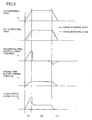
- the above-described integral-term electric-current component is may be an electric-current component that is required for generating the motor force whose amount is dependent on the negative efficiency ⁇ N , since the integral-term electric-current component is may be, generally, in view of the actuator efficiency, an electric-current component that is required for maintaining the rotational angle ⁇ of the motor 140. Therefore, the integral gain K I as a gain of the second term of the right side of the above expression (for determining the target electric current amount i*) is set such that the integral-term electric-current component is is dependent on the negative -efficiency characteristic. For example, in execution of the roll restraining control for restraining the roll caused during turning of the vehicle, as shown in Fig.
- the displacement force i.e., the roll restraining force that is to be generated by the adjuster device 120 is changed whereby the target rotational angle ⁇ * of the motor 140 is changed.
- the integral-term electric-current component is is determined in accordance with the negative efficiency ⁇ N such that the rotational angle ⁇ of the motor 140 is substantially held in the target rotational angle ⁇ * throughout an initial stage [a], an intermediate stage [b] and a final stage [c] of the turning of the vehicle.
- the above-described proportional-term electric-current component i h is provided for eliminating the deviation of the actual rotational angle ⁇ from the target rotational angle ⁇ * under application of an external force
- the proportional gain K P as a gain of the first term of the right side of the above expression is set such that the proportional-term electric-current component i h is compensated (increased or reduced) suitably depending on the rotational angle deviation ⁇ .
- the motor 140 has to be supplied with the electric current whose amount enables generation of the motor force such that an amount of the generated motor force is not smaller than an amount dependent on the positive efficiency characteristic.
- the proportional gain K P is set to a value that enables generation of the motor force according to the positive efficiency characteristic without the rotational angle deviation ⁇ being considerably increased.
- the positive efficiency ⁇ P and the negative efficiency ⁇ N of the actuator 126 are taken into account, by determining the target electric current amount i* according to the above expression in which the proportional gain K P and the integral gain K I are suitably set.
- the direction of the motor force generated by the electromagnetic motor 140 is dependent on whether the target electric current amount i* is a positive value or a negative value.
- the duty ratio and the direction of the generated motor force are determined based on the target electric current amount i*.
- a command indicative of the determined duty ratio and motor force direction is supplied to the inverter 174, so that the drive of the motor 140 is controlled based on the command by the inverter 174.
- each of the four adjuster devices 120 is configured to generate the displacement force that is to be generated, thereby restraining undesirable motion of the vehicle body such as roll and pitch of the vehicle body and damping the sprung-portion vibration.
- each adjuster device 120 has a difficulty in coping with vibrations of relatively high frequency.
- each hydraulic damper 56 included in the system 10 is provided by a damper suitable for damping vibrations of relatively high frequency, so that transmission of the vibrations of relatively high frequency to the vehicle body is restrained by operation of the damper 56. That is, in the present system 10, the vibrations of low frequency range including a resonance frequency of the sprung member is coped with by the adjuster device 120, because the vibrations of the low frequency range can be followed by operation of the actuator 126. Meanwhile, the vibrations of high frequency range including a resonance frequency of the unsprung member is coped with by the damper 56. For assuring this function, the damper 56 has a damping coefficient that is tuned to be low as much as possible.
- the value of the damping coefficient of the hydraulic damper 56 affects not only transmittability of vibration from the unsprung portion to the sprung portion but also road-holding ability of the wheel. Specifically described, as shown in Fig. 10 , with respect to fluctuation of a load applied to a contact portion of the wheel which is in contact with a road surface, a rate of fluctuation of the load applied to the contact portion of the wheel upon occurrence of vibrations of the unsprung-member resonance frequency range is increased with reduction of the damping coefficient. Particularly, when the damping coefficient is reduced to a certain degree, the load fluctuation rate is considerably increased, as is understood from Fig. 10 .
- the load fluctuation rate and the road-holding ability correlate with each other such that the road-holding ability is reduced with increase of the load fluctuation rate.
- the road-holding ability upon occurrence of vibrations of the unsprung-member resonance frequency range is reduced with reduction of the damping coefficient. That is, when the damping coefficient is reduced to a certain degree, the road-holding ability upon occurrence of vibrations of the unsprung-member resonance frequency range is considerably reduced. Therefore, in the present system 10, the damping coefficient of the hydraulic damper 56 is set by taking account of a suitable balance between the road-holding ability upon occurrence of vibrations of relatively high frequency range and the transmittability of vibrations of the relatively high frequency range.
- the damping coefficient of the damper 56 is set to 1500 N ⁇ sec / m (as a value obtained under an assumption that the hydraulic damping force is arranged to act directly on the wheel that is displaced relative to the vehicle body), which is lower than a half of 3000-5000 N ⁇ sec / m that is a damping coefficient of a conventional shock absorber of a suspension system not having the adjuster device 120.
- the damping coefficient of the hydraulic damper 56 is set as described above, it is possible to restrain transmission of vibrations of high frequency range (which are difficult to be damped by the adjuster device 120) to the sprung portion while obtaining a certain degree of the road-holding ability upon occurrence of vibrations of the high frequency range.
- the hydraulic damping force generated by the hydraulic damper 56 acts against displacement of the sprung and unsprung portions relative to each other, there is a risk that the hydraulic damping force would affect the control of the adjuster device 120, particularly, the sprung-portion vibration damping control executed to cause the displacement force to act as the damping force against vibration of the sprung portion.
- the hydraulic damping force is generated in case of occurrence of vibrations of the relatively high frequency range, for coping with the vibrations of the relatively high frequency range, and is inhibited from being generated in the other case, for eliminating influence of the hydraulic damping force affecting the control of the adjuster device 120.
- the hydraulic damper force is normally inhibited from being generated, by placing the electromagnetic clutch 72 in its deenergized state, and is allowed to be generated in response to displacement of the sprung and unsprung portions relative to each other, in case of occurrence of the unsprung-portion resonance frequency vibration, by placing the clutch 72 in its energized state.
- a damping force reducing control is executed to reduce the amount of the hydraulic damping force to 0 (zero).
- a control in which as if the damping coefficient of the hydraulic damper 56 were tuned to 0 (zero).
- the judgment as to whether the unsprung-portion resonance frequency vibration is occurring or not can be made by seeing an intensity of a component of unsprung-portion resonance frequency range, which is extracted from the sprung-portion vibration through a suitable filtering procedure. Described specifically, the sprung-portion vertical acceleration Gu is detected by the vertical acceleration sensor 196, and vibrations of the unsprung-portion resonance frequency range are extracted based on the detected sprung-portion vertical acceleration Gu, wherein the unsprung-portion resonance frequency range has a center corresponding to the unsprung-portion resonance frequency, and ranges from 3Hz subtracted from the unsprung-portion resonance frequency to 3Hz added to the unsprung-portion resonance frequency.
- a maximum value ⁇ of amplitudes as the intensities of the vibrations of the unsprung-portion resonance frequency range is calculated.
- a threshold value ⁇ 1 it is judged that the unsprung-portion resonance frequency vibration is occurring. That is, it is judged that the unsprung-portion resonance frequency vibration is occurring when the intensity of the unsprung-portion resonance frequency vibration is higher than a threshold intensity value, and it is judged that the unsprung-portion resonance frequency vibration is not occurring when the intensity of the unsprung-portion resonance frequency vibration is not higher than the threshold intensity value.
- the displacement force which is to be generated by the adjuster device 120, is controlled through an adjuster-device controlling routine program that is executed by the adjuster controller 176, as shown in flow chart of Fig. 11 .
- the electromagnetic clutch 72 of the hydraulic damper 56 is controlled through a damper controlling routine program that is executed by the hydraulic damper controller 180, as shown in flow chart of Fig. 12 .
- These two routine programs are concurrently and repeatedly executed at a short time interval (e.g., several tens of milliseconds), while an ignition switch of the vehicle is placed in its ON state.
- the routine programs will be described with reference to the flow charts of Figs. 11 and 12 .
- adjuster-device controlling routine program is executed for each one of the actuators 126 of the respective four adjuster devices 120, and that the damper controlling routine program is executed for each one of the electromagnetic clutches 72 of the respective four hydraulic dampers 56.
- control procedures for one of the actuators 126 and control procedures for one of the electromagnetic clutches 72 will be described in the interest of simplification of the description.
- step S1 that is implemented to calculate the sprung-portion absolute velocity Vu, based on the sprung-portion vertical acceleration Gu detected by the vertical acceleration sensor 196.
- step S1 is followed by step S2 in which the vibration damping target rotational angle component ⁇ * U directed to the sprung-portion vibration damping control is determined based on the calculated sprung-portion absolute velocity Vu.
- step S3 is implemented to calculate the lateral acceleration parameter value Gy*, based on the lateral acceleration measured value Gyr (detected by the lateral acceleration sensor 192) and the lateral acceleration estimated value Gyc.
- Step S3 is followed by step S4 in which the roll restraining target rotational angle component ⁇ * R directed to the roll restraining control is determined based on the calculated lateral acceleration parameter value Gy*.
- step S5 is implemented to detect the longitudinal acceleration Gzg through the longitudinal acceleration sensor 194.
- step S6 is followed by step S6 in which the pitch restraining target rotational angle component ⁇ * P directed to the pitch restraining control is determined based on the detected longitudinal acceleration Gzg.
- step S7 is implemented to determine the target motor rotational angle ⁇ * as a sum of the vibration damping component ⁇ * U , roll restraining component ⁇ * R and pitch restraining component ⁇ * P .
- step S8 After determination of the target motor rotational angle ⁇ *, the actual rotational angle ⁇ is obtained based on a value detected by the motor rotational angle sensor 154 in step S8, and the deviation ⁇ of the actual rotational angle ⁇ from the target rotational angle ⁇ * is determined in step S9. Then; in step S10, the target electric current amount i* is determined based on the rotational angle deviation ⁇ and the above-described expression in accordance with the PI control rule.
- step S11 One cycle of execution of the adjuster-device controlling routine program is completed with step S11 in which a control signal based on the determined target electric current amount i* is transmitted to the inverter 174.
- step S21 in which the sprung-portion vertical acceleration Gu is detected by the vertical acceleration sensor 196.
- step S22 the maximum value ⁇ of amplitudes of vibrations of the unsprung-portion resonance frequency range is calculated, after the vibrations of the unsprung-portion resonance frequency range have been extracted through the filtering procedure.
- step S23 is followed by step S23 that is implemented to judge whether the calculated maximum value a of amplitudes is larger than the threshold value ⁇ 1 .
- step S24 a command requesting the electromagnetic clutch 72 to be placed in the energized state is directed to the driver 178.
- the control flow goes to step S25 in which a command requesting the electromagnetic clutch 72 to be placed in the deenergized state is directed to the driver 178.
- the adjuster controller 176 which executes the above-described adjuster-device controlling routine program, can be considered to include functional portions as shown in Fig. 13 , in view of the procedures in the execution of the controlling routine program.
- the adjuster controller 176 has a displacement-force controlling portion 210 as a functional portion assigned to implement steps S1 through S11, namely, as a functional portion configured to control the displacement force that is to be generated by the adjuster device 120.
- the displacement-force controlling portion 210 has a sprung-portion vibration damping control executing portion 212, a roll restraining control executing portion 214 and a pitch restraining control executing portion 216.
- the sprung-portion vibration damping control executing portion 212 is a functional portion assigned to implement steps S1 and S2, namely, a functional portion configured to execute the sprung-portion vibration damping control.
- the roll restraining control executing portion 214 is a functional portion assigned to implement steps S3 and S4, namely, a functional portion configured to execute the roll restraining control.
- the pitch restraining control executing portion 216 is a functional portion assigned to implement steps S5 and S6, namely, a functional portion configured to execute the pitch restraining control.
- the damper controller 180 which executes the above-described damper controlling routine program, also can be considered to include functional portions as shown in Fig. 13 , in view of the procedures in the execution of the controlling routine program.
- the damper controller 180 has an unsprung-portion resonance frequency vibration judging portion 218 and a damping-force controlling portion 220.
- the unsprung-portion resonance frequency vibration judging portion 218 is a functional portion assigned to implement steps S21 through S23, namely, a functional portion configured to judge whether the unsprung-portion resonance frequency vibration is occurring or not.
- the damping-force controlling portion 220 is a functional portion assigned to implement steps S24 and S25, namely, a functional portion configured to control the hydraulic damping force that is to be generated by the hydraulic damper 56.
- the damping force controlling portion 220 has a damping-force generating portion 222 and a damping-force reducing control executing portion 224.
- the damping-force generating portion 222 is a functional portion assigned to implement step S24, namely, a functional portion configured to generate the hydraulic damping force.
- the damping-force reducing control executing portion 224 is a functional portion assigned to implement step S25, namely, a functional portion configured to execute the damping-force reducing control by inhibiting generation of the hydraulic damping force.
- Fig. 14 schematically shows a vehicle suspension system 230 that is constructed according to a second embodiment of the invention.
- the above-described suspension system 10 according to the first embodiment is equipped with the hydraulic dampers 56 of rotary type.
- the present suspensions system 230 is equipped with hydraulic dampers 232 of cylinder type.
- the same reference signs as used in the above-described suspension system 10 will be used to identify the functionally corresponding elements, and redundant description of these elements is not provided.
- the suspension system 230 includes four suspension devices 234 that are provided for respective four wheels 12 (i.e., front right, front left, rear right and rear left wheels 12).
- each suspension device 234 of independent type is provided by a multi-link suspension, and is equipped with an arm assembly as the wheel holder, like each suspension device 20 of the above-described suspension system 10 according to the first embodiment.
- Each suspension device 234 has a coil spring 236 as the suspension spring and the hydraulic damper 232 of cylinder type, which are disposed in parallel with each other between the mount portion 54 and the second lower arm 36.
- the hydraulic damper 232 is constructed to include a generally tubular-shaped damper housing 240, a piston 242 and a piston rod 244.
- the damper housing 240 is connected to the second lower arm 36, and stores a working fluid therein.
- the piston 242 is fluid-tightly and slidably fitted inside the damper housing 240.
- the piston rod 244 has a lower end portion connected to the piston 242, and an upper end portion projecting upwardly from the damper housing 240.
- the piston rod 244 extends through a cap portion 250 that is provided in an upper portion of the damper housing 240, and is in sliding contact with the cap portion 250 via a seal.
- An inside space of the damper housing 240 is divided by the piston 242 into an upper chamber 248 and a lower chamber 246 that are located on respective upper and lower sides of the piston 242.
- the damper 232 is of twin-tube type, so that the damper housing 240 is constructed to include an outer cylinder 252 and an inner cylinder 254 such that a reservoir chamber 256 is defined between the outer and inner cylinders 252, 254.
- the piston 242 is ffuid-tightly and slidably fitted inside the inner cylinder 254.
- the hydraulic damper 232 is provided with a solenoid 260 having a housing 262 that is connected at its peripheral portion to the mount portion 50 via a rubber cushion.
- An upper end portion of the piston rod 244 is fixedly connected to a lower portion of the housing 262 of the solenoid 260, whereby the piston rod 244 is fixed relative to the mount portion 50.
- the piston rod 244 is hollow-like shaped, so as to have a through-hole 266 extending therethrough.
- a rod 268 of the solenoid 260 is introduced in the through-hole 266 so as to be axially movable, so that the rod 268 is axially moved upon activation of the solenoid 260.
- the through-hole 266 of the piston rod 244 has a large diameter portion 270 and a small diameter portion 272 that extends downwardly from the large diameter portion 270.
- a step portion 274 is provided in a boundary between the large diameter portion 270 and the small diameter portion 272 of the through-hole 266.
- a communication passage 276 is provided on an upper side of the step portion 274, so as to allow communication between the upper chamber 248 and the through-hole 266.
- the upper chamber 248 and the lower chamber 246 are held in communication with each other via the communication passage 276 and the through-hole 266.
- the above-described rod 268 of the solenoid 260 is inserted from an upper end portion of the piston rod 244.
- the rod 268 has a lower end portion that is introducible into the small diameter portion 272 of the through-hole 266.
- the rod 268 has an outside diameter that is larger than an inside diameter of the small diameter portion 272 of the through-hole 266, so that the small diameter portion 272 of the through-hole 266 can be closed by the lower end portion of the rod 268 upon downward movement of the rod 268. That is, when the solenoid 260 is placed in its deenergized state, the upper and lower chambers 248, 246 are held in communication with each other via the communication passage 276 and the through-hole 266.
- the through-hole 266 is closed by the rod 268 of the solenoid 260 whereby the communication of the upper and lower chambers 248, 246 via the communication passage 276 and the through-hole 266 is cut off.
- the hydraulic damper 232 allows transfer of the working fluid between the upper and lower chambers 248, 246 via vertically extending communication passages formed through the piston 242, upon displacement of the piston 242.
- a flow restrictor provided in each of the vertically extending communication passages applies resistance to the transfer of the working fluid between the upper and lower chambers 248, 246.
- a base valve body 278 disposed between the lower chamber 246 and the reservoir chamber 264 applies resistance to transfer of the working fluid between the lower chamber 246 and the reservoir chamber 264.
- the hydraulic damper 232 is configured to generate a damping force which is based on the resistance force applied to the transfer of the working fluid caused by displacement of the piston 242 and which acts against the displacement of the piston 242, i.e., displacement of the sprung and unsprung portions toward and away from each other. Further, the damper 232 is capable of changing an amount of the damping force by operation of the solenoid 260, without depending on relative velocity of the sprung and unsprung portions. In other words, the damper 232 is constructed to be capable of changing its damping coefficient, i.e., damping characteristic against displacement of the sprung and unsprung portions relative to each other.
- the damper 232 has a damping force changer that is at least partially constituted by the solenoid 260, through-hole 266 and communication passage 276. The damping force changer has a function of changing the damping coefficient of the damper 232.
- a lower retainer 280 having an annular shape is mounted on an outer peripheral portion of the damper housing 240.
- An upper retainer 282 having an annular shape is disposed on a lower surface of the mount portion 50, with a rubber vibration isolator being interposed between the upper retainer 282 and the lower surface of the mount portion 50.
- the coil spring 236 is interposed between the upper and lower retainers 282, 280 so as to be supported by the retainers 282, 280.
- An annular member 284 is fixedly mounted on an outer peripheral portion of a portion of the piston rod 244 which is accommodated in the upper chamber 248.
- An annular cushion rubber 286 is bonded onto an upper surface of the annular member 284.
- a tubular cushion rubber 288 is bonded onto a lower surface of the solenoid 260.
- the annular member 284 is brought into contact with a lower surface of the cap portion 250 of the damper housing 240 through the cushion rubber 286.
- an upper surface of the cap portion 250 is brought into contact with the lower surface of the solenoid 260 through the tubular cushion rubber 288. That is, the damper 232 has a bound stopper and a rebound stopper, i.e., stoppers against the relative displacement of the vehicle body and the wheel toward and away from each other.
- an adjuster electronic control unit (adjuster ECU) 170 is provided for controlling the four adjuster devices 120
- a damper electronic control unit (damper ECU) 300 is provided for controlling the four dampers 232.
- the controller of the present suspension system 230 is constructed to include the two ECUs 170, 300.
- the damper ECU 300 is configured to control operations of the solenoids 260 of the respective dampers 232, and includes four drivers 302 serving as drive circuits and a damper controller 304 that is constituted principally by a computer including CPU, ROM and RAM (see Fig. 18 ).
- the drivers 302 are connected to a battery 184 via a converter 182, and are connected to the solenoids 260 of the respective dampers 232. Further, the damper controller 304 is connected to the drivers 302, so that the operations of the solenoids 260 are controllable by controlling the drivers 302.
- each hydraulic damper 232 of the present system 230 is disposed in parallel with the corresponding adjuster device 120, so that the hydraulic damping force generated by the damper 232 acts on the sprung and unsprung portions.
- the control of the adjuster device 120 could be affected by the hydraulic damping force generated by the damper 232.
- the damping force reducing control is executed by taking account of the road-holding ability of the wheel and the influence of the hydraulic damping force affecting the control of the adjuster device 120.
- the damping force reducing control is not a control for inhibiting generation of the hydraulic damping force but a control for reducing the damping coefficient of the hydraulic damper 232.
- the damping coefficient is normally made low so as to reduce influence of the hydraulic damping force affecting control of the adjuster device 120, and is increased in case of occurrence of the unsprung-portion resonance frequency vibration so as to increase the road-holding ability of the wheel upon occurrence of the unsprung-portion resonance frequency vibration.
- the through-hole 266 is normally held open by placing the solenoid 260 in its deenergized state so as to reduce the damping coefficient, i.e., the damping characteristic against displacement of the sprung and unsprung portions toward and away from each other, and is closed by placing the solenoid in its energized state in case of occurrence of the unsprung-portion resonance frequency vibration so as to increase the damping coefficient.
- the damping coefficient of the hydraulic damper 232 when the through-hole 266 is closed, is set to 1500 N ⁇ sec / m (as a value obtained under an assumption that the hydraulic damping force is arranged to act directly on the wheel that is displaced relative to the vehicle body) by taking account of a suitable balance between the road-holding ability upon occurrence of vibrations of relatively high frequency range and transmittability of vibrations of the relatively high frequency range.
- the damping coefficient of the damper 232 when the through-hole 266 is open, is set to 500 N ⁇ sec / m which is about one-tenth to one-sixth as low as 3000-5000 N ⁇ sec / m as a damping coefficient of a conventional shock absorber of a suspension system. Therefore, in the present system 230, it is possible to reduce influence of the hydraulic damping force affecting the control of the adjuster device 120 when the unsprung-portion resonance frequency vibration is not occurring.
- the adjuster device 120 is controlled through the adjuster-device controlling routine program that is executed by the adjuster controller 176, as shown in flow chart of Fig. 11 .
- the solenoid 260 of the hydraulic damper 232 is controlled through a damper controlling routine program that is executed by the hydraulic damper controller 304, as shown in flow chart of Fig. 17 .
- These two routine programs are concurrently and repeatedly executed at a short time interval (e.g., several tens of milliseconds), while the ignition switch is placed in its ON state. Since the adjuster-device controlling routine program is the same as that in the above-described first embodiment, it will not be described. Since the damper controlling routine program is similar to that in the above-described first embodiment, it will be briefly described.
- the damper controlling routine program like in the damper controlling routine program in the above-described first embodiment, it is first judged whether the unsprung-portion resonance frequency vibration is occurring or not in steps S31 through S33. When it is judged that the unsprung-portion resonance frequency vibration is occurring, a command requesting the solenoid 260 to be placed in its energized state is transmitted to the driver 302 in step S34. When it is judged that the unsprung-portion resonance frequency vibration is not occurring, a command requesting the solenoid 260 to be placed in its deenergized state is transmitted to the driver 302 in step S35, so as to execute the damping force reducing control.
- the adjuster controller 176 of the adjuster ECU 170 (which executes the above-described adjuster-device controlling routine program) and the damper controller 302 of the damper ECU 300 (which executes the above-described damper controlling routine program) can be considered to include functional portions as shown in Fig. 18 , in view of the procedures in the executions of the controlling routine programs. Since the functional portions included in the adjuster controller 176 of the adjuster ECU 170 are the same as those in the above-described first embodiment, they will not be described. Since the functional portions included in the damper controller 302 of the damper ECU 300 are similar to those included in the damper controller 180 of the damper ECU 172 in the above-described first embodiment, they will be briefly described.
- the damper controller 302 has an unsprung-portion resonance frequency vibration judging portion 310 and a damping-force controlling portion 312.
- the unsprung-portion resonance frequency vibration judging portion 310 is a functional portion assigned to implement steps S31 through S33, namely, a functional portion configured to judge whether the unsprung-portion resonance frequency vibration is occurring or not.
- the damping-force controlling portion 312 is a functional portion assigned to implement steps S34 and S35, namely, a functional portion configured to control the hydraulic damping force that is to be generated by the hydraulic damper 232.
- the damping-force controlling portion 312 has a damping-coefficient increasing portion 314 and a damping-force reducing control executing portion 316.
- the damping-coefficient increasing portion 314 is a functional portion assigned to implement step S34, namely, a functional portion configured to increase the damping coefficient.
- the damping-force reducing control executing portion 316 is a functional portion assigned to implement step S35, namely, a functional portion configured to execute the damping-force reducing control by reducing the damping coefficient.
Landscapes
- Engineering & Computer Science (AREA)
- Mechanical Engineering (AREA)
- General Engineering & Computer Science (AREA)
- Vehicle Body Suspensions (AREA)
- Vibration Prevention Devices (AREA)
Claims (11)
- Aufhängungssystem (10; 230) für ein Fahrzeug mit:(a) einer Aufhängungsfeder (52; 236), die zwischen gefederten und ungefederten Abschnitten (50, 36) des Fahrzeugs angeordnet ist;(b) einem hydraulischen Dämpfer (56; 232), der parallel zu der Aufhängungsfeder angeordnet ist und dazu aufgebaut ist, eine Dämpfungskraft gegen die Verschiebung der gefederten und ungefederten Abschnitte relativ zueinander so zu erzeugen, dass eine Größe der Dämpfungskraft durch eine Dämpfungskraftänderungseinrichtung (72; 260, 266, 276) änderbar ist, die in dem Dämpfer enthalten ist;(c) einem Verschiebungskrafterzeuger (120), der parallel zu der Aufhängungsfeder angeordnet ist und dazu aufgebaut ist, auf der Grundlage einer Motorkraft, die von einem in dem Verschiebungskrafterzeuger enthaltenen elektromagnetischen Motor (140) erzeugt wird, eine Verschiebungskraft zu erzeugen, die die gefederten und ungefederten Abschnitte dazu veranlasst, zueinander hin oder voneinander weg verschoben zu werden; und(d) einer Steuerung (170, 172; 170, 300), die (d-1) einen Dämpfungskraftsteuerabschnitt (220; 312), der dazu aufgebaut ist, die Dämpfungskraftänderungseinrichtung so zu steuern, dass die von dem Dämpfer zu erzeugende Dämpfungskraft gesteuert wird, und (d-2) einen Verschiebungskraftsteuerabschnitt (210) aufweist, der dazu aufgebaut ist, eine Betätigung des elektromagnetischen Motors so zu steuern, dass die von dem Verschiebungskrafterzeuger zu erzeugende Verschiebungskraft gesteuert wird,wobei der Verschiebungskraftsteuerabschnitt dazu aufgebaut ist, eine Schwingungsdämpfungssteuerung für den gefederten Abschnitt durchzuführen, um die von dem Verschiebungskrafterzeuger zu erzeugende Verschiebungskraft so zu steuern, dass die erzeugte Verschiebungskraft als eine Dämpfungskraft gegen eine im gefederten Abschnitt auftretende Schwingung des gefederten Abschnitts wirkt,
wobei das Aufhängungssystem dadurch gekennzeichnet ist, dass
der Dämpfungskraftsteuerabschnitt dazu aufgebaut ist, bei Ausführung der Schwingungsdämpfungssteuerung durch den Verschiebungskraftsteuerabschnitt eine Dämpfungskraftverringerungssteuerung durchzuführen, um die von dem Dämpfer erzeugte Dämpfungskraft abhängig von einer Eigenfrequenzschwingung des ungefederten Abschnitts zu verringern, die in dem Fahrzeug auftritt und die zu einer Eigenfrequenz des ungefederten Abschnitts passt, so dass die Dämpfungskraft, die von dem Dämpfer erzeugt wird, in einer Situation niedriger Intensität, in der eine Intensität der Eigenfrequenzschwingung des ungefederten Abschnitts nicht höher als ein Intensitätsschwellenwert ist, kleiner ist als in einer Situation hoher Intensität eingestellt wird, in der die Intensität höher als der Intensitätsschwellenwert ist. - Aufhängungssystem (10; 230) nach Anspruch 1, wobei die Dämpfungskraftverringerungssteuerung ausgeführt wird, um die von dem Dämpfer (56; 232) zu erzeugende Dämpfungskraft so zu verringern, dass ein Dämpfungskoeffizient des Dämpfers in der Situation niedriger Intensität nicht größer als 500 N●sec/m ist.
- Aufhängungssystem (10) nach Anspruch 2, wobei die Dämpfungskraftverringerungssteuerung ausgeführt wird, um die von dem Dämpfer (56) erzeugte Dämpfungskraft so zu verringern, dass eine Größe der erzeugten Dämpfungskraft in der Situation niedriger Intensität im Wesentlichen Null ist.
- Aufhängungssystem (10) nach Anspruch 3,
wobei der Dämpfer (56) einen ersten verriegelten Abschnitt (62, 64) umfasst, der mit dem gefederten Abschnitt (50) verriegelt ist, und einen zweiten verriegelten Abschnitt (60) aufweist, der mit dem ungefederten Abschnitt (36) verriegelt ist, und dazu aufgebaut ist, die Dämpfungskraft gegen die Verschiebung der gefederten und ungefederten Abschnitte relativ zueinander zu erzeugen, indem er eine Widerstandskraft gegen die Verschiebung der ersten und zweiten verriegelten Abschnitte gegeneinander erzeugt,
wobei die Dämpfungskraftänderungseinrichtung (72) eine Verriegelungslösungseinrichtung (72) aufweist, die dazu aufgebaut ist, die Verriegelung zwischen dem gefederten Abschnitt und dem ersten verriegelten Abschnitt und/oder die Verriegelung zwischen dem ungefederten Abschnitt und dem zweiten verriegelten Abschnitt zu lösen,
und wobei der Dämpfungskraftsteuerabschnitt (220) dazu aufgebaut ist, die Verriegelungslösungseinrichtung in der Dämpfungskraftverringerungssteuerung dazu zu veranlassen, die Verriegelung zwischen dem gefederten Abschnitt und dem ersten verriegelten Abschnitt und/oder die Verriegelung zwischen dem ungefederten Abschnitt und dem zweiten verriegelten Abschnitt zu lösen. - Aufhängungssystem (10; 230) nach einem der Ansprüche 1 bis 4, wobei der Dämpfungskraftsteuerabschnitt (220; 312) dazu aufgebaut ist, bei der Ausführung der Schwingungsdämpfungssteuerung für den gefederten Abschnitt die vom Dämpfer (56, 232) zu erzeugende Dämpfungskraft so zu steuern, dass ein Dämpfungskoeffizient des Dämpfers in der Situation hoher Intensität in einem Bereich von 1000 bis 2000 N•sec/m liegt.
- Aufhängungssystem (10; 230) nach einem der Ansprüche 1 bis 5, wobei der Verschiebungskraftsteuerabschnitt (210) dazu aufgebaut ist, in der Schwingungsdämpfungssteuerung für den gefederten Abschnitt die vom Verschiebungskrafterzeuger (120) zu erzeugende Verschiebungskraft so zu steuern, dass eine Größe zumindest einer Komponente der erzeugten Verschiebungskraft von einer Absolutgeschwindigkeit des gefederten Abschnitts (50) abhängt.
- Aufhängungssystem (10; 230) nach einem der Ansprüche 1 bis 6, wobei der Verschiebungskraftsteuerabschnitt (210) dazu aufgebaut ist, eine Haltungsänderungsbeschränkungssteuerung zum Beschränken einer Haltungsänderung einer Karosserie des Fahrzeugs durch Steuern der von dem Verschiebungskrafterzeuger (120) zu erzeugenden Verschiebungskraft so durchzuführen, dass mindestens eine Komponente der erzeugten Verschiebungskraft als eine Wankbeschränkungskraft zum Beschränken des Wankens der Karosserie des Fahrzeugs und/oder eine Nickbeschränkungskraft zum Beschränken des Nickens der Karosserie des Fahrzeugs wirkt.
- Aufhängungssystem (10; 230) nach einem der Ansprüche 1 bis 7,
wobei der Verschiebungskrafterzeuger(120) Folgendes umfasst: (c-1) einen elastischen Körper (122), der an einem von gegenüberliegenden Endabschnitten mit einem der gefederten und ungefederten Abschnitte (50, 36) verbunden ist, und (c-2) ein elektromagnetisches Stellglied (126), das zwischen dem anderen aus den gegenüberliegenden Endabschnitten des elastischen Körpers und dem anderen aus den gefederten und ungefederten Teilen angeordnet ist und das den elastischen Körper mit dem anderen aus den gefederten und ungefederten Teilen verbindet,
und wobei das elektromagnetische Stellglied den elektromagnetischen Motor (140) umfasst und dazu aufgebaut ist, eine Stellkraft auf der Grundlage der von dem elektromagnetischen Motor erzeugten Motorkraft so zu erzeugen, dass die erzeugte Stellkraft derart auf den elastischen Körper wirkt, dass sie eine Größe der Verformung des elastischen Körpers ändert, die von einer Größe der Betätigung des Stellglieds abhängt, und so, dass die erzeugte Stellkraft so über den elastischen Körper an die gefederten und ungefederten Abschnitte übertragen wird, dass sie als die Verschiebungskraft wirkt. - Aufhängungssystem (10; 230) nach Anspruch 8,
wobei der elastische Körper (122) Folgendes umfasst: (c-1-i) einen Wellenabschnitt (130), der an einer Karosserie des Fahrzeugs drehbar gelagert ist und (c-1-ii) einen Armabschnitt (132), der sich von einem der gegenüberliegenden Endabschnitte des Wellenabschnitts in einer Richtung erstreckt, die den Wellenabschnitt schneidet und der an seinem entfernten Endabschnitt mit einem Radlager (30, 32, 34, 36, 38) verbunden ist, das ein Rad (12) des Fahrzeugs lagert,
und wobei das Stellglied (126) an der Karosserie des Fahrzeugs befestigt ist und dazu aufgebaut ist, den Wellenabschnitt durch die von dem Stellglied erzeugte Stellkraft um eine Achse des Wellenabschnitts zu drehen. - Aufhängungssystem (10; 230) nach Anspruch 8 oder 9, wobei das Stellglied (126) dazu aufgebaut ist, ein positives/negatives Effizienzprodukt aufzuweisen, das nicht größer als 1/2 ist,
wobei das positive/negative Effizienzprodukt als ein Produkt einer positiven Effizient des Stellglieds und einer negativen Effizienz des Stellglieds definiert ist, wobei
die positive Effizienz als ein Verhältnis einer Größe einer externen Kraft, die auf das Stellglied wirkt, zu einer Größe der Motorkraft definiert ist, die mindestens benötigt wird, um die Betätigung des Stellglieds gegen die externe Kraft zu bewirken, und
die negative Effizienz als ein Verhältnis einer Größe der Motorkraft, die mindestens benötigt wird, um die Betätigung des Stellglieds durch eine auf das Stellglied wirkende externe Kraft zu verhindern, zu einer Größe der externen Kraft definiert ist. - Aufhängungssystem (10; 230) nach einem der Ansprüche 8 bis 10,
wobei das Stellglied (126) eine Drehzahluntersetzung (142) umfasst, die dazu aufgebaut ist, eine von dem elektromagnetischen Motor (140) eingegebene Bewegung zu untersetzen und dazu aufgebaut ist, die untersetzte Bewegung als die Betätigung des Stellglieds auszugeben,
und wobei die Drehzahluntersetzung ein Drehzahlverhältnis aufweist, das nicht höher als 1/100 ist.
Applications Claiming Priority (2)
| Application Number | Priority Date | Filing Date | Title |
|---|---|---|---|
| JP2008044014A JP4930411B2 (ja) | 2008-02-26 | 2008-02-26 | 車両用サスペンションシステム |
| PCT/JP2009/053804 WO2009107832A1 (en) | 2008-02-26 | 2009-02-24 | Suspension system for vehicle |
Publications (2)
| Publication Number | Publication Date |
|---|---|
| EP2244894A1 EP2244894A1 (de) | 2010-11-03 |
| EP2244894B1 true EP2244894B1 (de) | 2012-10-31 |
Family
ID=40626747
Family Applications (1)
| Application Number | Title | Priority Date | Filing Date |
|---|---|---|---|
| EP09715426A Not-in-force EP2244894B1 (de) | 2008-02-26 | 2009-02-24 | Aufhängungssystem für fahrzeug |
Country Status (4)
| Country | Link |
|---|---|
| US (1) | US8240679B2 (de) |
| EP (1) | EP2244894B1 (de) |
| JP (1) | JP4930411B2 (de) |
| WO (1) | WO2009107832A1 (de) |
Families Citing this family (27)
| Publication number | Priority date | Publication date | Assignee | Title |
|---|---|---|---|---|
| EP2065295A1 (de) * | 2007-11-27 | 2009-06-03 | TNO Bedrijven B.V. | Aufhängungsanordnung zur Aufhängung des Fahrerhauses eines LKWs oder eines ähnlichen Fahrzeugs |
| WO2010131341A1 (ja) * | 2009-05-13 | 2010-11-18 | トヨタ自動車株式会社 | 制振制御装置 |
| US9592714B2 (en) | 2010-09-03 | 2017-03-14 | Toyota Jidosha Kabushiki Kaisha | Vehicle control device |
| JP5571519B2 (ja) * | 2010-09-27 | 2014-08-13 | 日立オートモティブシステムズ株式会社 | 車体姿勢制御装置 |
| JP5934470B2 (ja) * | 2011-03-30 | 2016-06-15 | 日立オートモティブシステムズ株式会社 | サスペンション装置 |
| JP5829268B2 (ja) * | 2011-04-27 | 2015-12-09 | 株式会社日立製作所 | 車両サスペンションシステム |
| DE102011102743A1 (de) | 2011-05-28 | 2012-11-29 | Audi Ag | Kraftfahrzeug |
| JP5733426B2 (ja) * | 2012-01-11 | 2015-06-10 | トヨタ自動車株式会社 | 車両 |
| DE102013002714B4 (de) * | 2013-02-16 | 2016-06-30 | Audi Ag | Drehfederanordnung für eine Radaufhängung eines Kraftfahrzeugs |
| DE102014003222B4 (de) * | 2014-03-05 | 2017-09-07 | Audi Ag | Koaxiale Federanordnung |
| JP6412409B2 (ja) * | 2014-11-07 | 2018-10-24 | Kyb株式会社 | サスペンション装置およびサスペンション制御装置 |
| CN104773045B (zh) * | 2015-04-27 | 2017-11-14 | 席玉林 | 组合弹簧补偿悬挂装置 |
| DE102016009081A1 (de) * | 2016-07-26 | 2018-02-01 | Man Truck & Bus Ag | Verfahren und Vorrichtung zur Steuerung oder Regelung einer Fahrerhaus-Lagerung |
| EP3357719A1 (de) * | 2017-02-06 | 2018-08-08 | Ovalo GmbH | Aktive radaufhängung für ein fahrzeug |
| JP2021195097A (ja) * | 2020-06-18 | 2021-12-27 | ロベルト・ボッシュ・ゲゼルシャフト・ミト・ベシュレンクテル・ハフツングRobert Bosch Gmbh | 制御装置、車両及び制御方法 |
| US20220410646A1 (en) * | 2021-06-25 | 2022-12-29 | Virginia Tech Intellectual Properties, Inc. | Automotive double damper suspension system |
| US11904841B2 (en) | 2021-10-12 | 2024-02-20 | DRiV Automotive Inc. | Suspension system integration with advanced driver assistance system |
| US11938772B2 (en) | 2021-10-12 | 2024-03-26 | DRiV Automotive Inc. | System for grading filling of a hydraulic suspension system |
| US11865889B2 (en) | 2021-10-12 | 2024-01-09 | DRiV Automotive Inc. | Suspension system with comfort valves between cross-over hydraulic circuits |
| US12168378B2 (en) | 2021-10-12 | 2024-12-17 | DRiV Automotive Inc. | Accumulator check systems and methods |
| US11912092B2 (en) | 2021-10-12 | 2024-02-27 | DRiV Automotive Inc. | Suspension leak check systems and methods |
| US11919355B2 (en) | 2021-10-12 | 2024-03-05 | DRiV Automotive Inc. | Valve diagnostic systems and methods |
| US12097739B2 (en) | 2021-10-12 | 2024-09-24 | DRiV Automotive Inc. | Pump rinsing systems and methods |
| US12059937B2 (en) * | 2021-10-12 | 2024-08-13 | DRiV Automotive Inc. | Suspension system with roll and pitch stiffness deactivation based on road profile information |
| US11865887B2 (en) | 2021-10-12 | 2024-01-09 | DRiV Automotive Inc. | Suspension system with incremental roll and pitch stiffness control |
| MA57938B1 (fr) * | 2022-09-26 | 2024-07-31 | Université Hassan 1er de Settat | Système de stabilisation par suspension hydro-électromagnétique |
| JP2025035781A (ja) * | 2023-09-04 | 2025-03-14 | トヨタ自動車株式会社 | サスペンション制御システム |
Family Cites Families (20)
| Publication number | Priority date | Publication date | Assignee | Title |
|---|---|---|---|---|
| US4491207A (en) * | 1983-07-15 | 1985-01-01 | Lord Corporation | Fluid control means for vehicle suspension system |
| JPS6118513A (ja) * | 1984-07-04 | 1986-01-27 | Nissan Motor Co Ltd | 車両用サスペンシヨン制御装置 |
| JPS61155010A (ja) * | 1984-10-24 | 1986-07-14 | Nissan Motor Co Ltd | 車両におけるサスペンシヨン制御装置 |
| JPH0811484B2 (ja) * | 1985-09-27 | 1996-02-07 | 日産自動車株式会社 | 車両のサスペンシヨン制御装置 |
| US5072965A (en) | 1989-05-31 | 1991-12-17 | Mitsubishi Denki K.K. | Suspension control device |
| EP0417702B1 (de) | 1989-09-11 | 1997-01-08 | Toyota Jidosha Kabushiki Kaisha | Aufhängungsregelsystem |
| JP2621512B2 (ja) | 1989-10-16 | 1997-06-18 | トヨタ自動車株式会社 | サスペンション制御装置 |
| US5293969A (en) | 1991-02-14 | 1994-03-15 | Atsugi Unisia Corporation | Electromagnetic suspension device |
| JP2917652B2 (ja) | 1991-06-10 | 1999-07-12 | 株式会社デンソー | サスペンション制御装置 |
| JP2603386Y2 (ja) | 1991-11-22 | 2000-03-06 | 株式会社ユニシアジェックス | 車両懸架装置 |
| JP4049999B2 (ja) | 2001-01-12 | 2008-02-20 | 本田技研工業株式会社 | サスペンションの制御方法 |
| JP3892228B2 (ja) | 2001-01-12 | 2007-03-14 | 本田技研工業株式会社 | 電磁アクチュエータの制御方法および電磁アクチュエータの制御装置 |
| JP4142551B2 (ja) | 2003-10-17 | 2008-09-03 | トヨタ自動車株式会社 | 車両懸架装置 |
| JP2006082751A (ja) * | 2004-09-17 | 2006-03-30 | Toyota Motor Corp | スタビライザシステム |
| JP4525918B2 (ja) | 2005-04-15 | 2010-08-18 | トヨタ自動車株式会社 | 減衰力発生システムおよびそれを含んで構成された車両用サスペンションシステム |
| JP4846439B2 (ja) * | 2006-05-15 | 2011-12-28 | トヨタ自動車株式会社 | 車両用サスペンションシステム |
| JP4333792B2 (ja) * | 2007-10-17 | 2009-09-16 | トヨタ自動車株式会社 | 車体ロール抑制システム |
| JP4877240B2 (ja) * | 2008-01-29 | 2012-02-15 | トヨタ自動車株式会社 | 車両用サスペンションシステム |
| JP4920006B2 (ja) * | 2008-05-15 | 2012-04-18 | トヨタ自動車株式会社 | 車両用サスペンションシステム |
| JP4935757B2 (ja) * | 2008-05-27 | 2012-05-23 | トヨタ自動車株式会社 | 車両用サスペンションシステム |
-
2008
- 2008-02-26 JP JP2008044014A patent/JP4930411B2/ja active Active
-
2009
- 2009-02-24 WO PCT/JP2009/053804 patent/WO2009107832A1/en not_active Ceased
- 2009-02-24 US US12/673,831 patent/US8240679B2/en not_active Expired - Fee Related
- 2009-02-24 EP EP09715426A patent/EP2244894B1/de not_active Not-in-force
Also Published As
| Publication number | Publication date |
|---|---|
| JP4930411B2 (ja) | 2012-05-16 |
| JP2009202622A (ja) | 2009-09-10 |
| EP2244894A1 (de) | 2010-11-03 |
| US8240679B2 (en) | 2012-08-14 |
| WO2009107832A1 (en) | 2009-09-03 |
| US20110025001A1 (en) | 2011-02-03 |
Similar Documents
| Publication | Publication Date | Title |
|---|---|---|
| EP2244894B1 (de) | Aufhängungssystem für fahrzeug | |
| EP2279088B1 (de) | Aufhängungssystem für ein fahrzeug | |
| US8195361B2 (en) | Vehicle suspension system | |
| EP2244895B1 (de) | Aufhängungssystem für fahrzeug | |
| JP4525651B2 (ja) | 車両用サスペンションシステム | |
| EP2170635B1 (de) | Aufhängungssystem | |
| US8296009B2 (en) | Suspension controller | |
| EP1894756B1 (de) | Fahrzeugaufhängungssystem | |
| KR100978772B1 (ko) | 차량 스태빌라이저 시스템 | |
| US7270335B2 (en) | Electromagnetic suspension apparatus for automotive vehicles and method for controlling electric motor of the same | |
| EP2202105B1 (de) | System zur einschränkung der rollbewegung einer fahrzeugkarosserie | |
| US20100207343A1 (en) | Suspension system for vehicle | |
| JP4941416B2 (ja) | 車両用サスペンションシステム | |
| JP4872782B2 (ja) | 車両用サスペンションシステム | |
| JP4867587B2 (ja) | 車両用サスペンションシステム | |
| EP4667248A1 (de) | Kraftfahrzeug mit aktiven aufhängungen und steuerverfahren für das kraftfahrzeug | |
| JP4872686B2 (ja) | 車両用サスペンションシステム |
Legal Events
| Date | Code | Title | Description |
|---|---|---|---|
| PUAI | Public reference made under article 153(3) epc to a published international application that has entered the european phase |
Free format text: ORIGINAL CODE: 0009012 |
|
| 17P | Request for examination filed |
Effective date: 20100223 |
|
| AK | Designated contracting states |
Kind code of ref document: A1 Designated state(s): AT BE BG CH CY CZ DE DK EE ES FI FR GB GR HR HU IE IS IT LI LT LU LV MC MK MT NL NO PL PT RO SE SI SK TR |
|
| AX | Request for extension of the european patent |
Extension state: AL BA RS |
|
| DAX | Request for extension of the european patent (deleted) | ||
| GRAP | Despatch of communication of intention to grant a patent |
Free format text: ORIGINAL CODE: EPIDOSNIGR1 |
|
| RIN1 | Information on inventor provided before grant (corrected) |
Inventor name: KAJINO, HIDENORI |
|
| GRAS | Grant fee paid |
Free format text: ORIGINAL CODE: EPIDOSNIGR3 |
|
| GRAA | (expected) grant |
Free format text: ORIGINAL CODE: 0009210 |
|
| AK | Designated contracting states |
Kind code of ref document: B1 Designated state(s): AT BE BG CH CY CZ DE DK EE ES FI FR GB GR HR HU IE IS IT LI LT LU LV MC MK MT NL NO PL PT RO SE SI SK TR |
|
| REG | Reference to a national code |
Ref country code: GB Ref legal event code: FG4D Ref country code: CH Ref legal event code: EP |
|
| REG | Reference to a national code |
Ref country code: AT Ref legal event code: REF Ref document number: 581786 Country of ref document: AT Kind code of ref document: T Effective date: 20121115 |
|
| REG | Reference to a national code |
Ref country code: IE Ref legal event code: FG4D |
|
| REG | Reference to a national code |
Ref country code: DE Ref legal event code: R096 Ref document number: 602009010821 Country of ref document: DE Effective date: 20121227 |
|
| RAP2 | Party data changed (patent owner data changed or rights of a patent transferred) |
Owner name: TOYOTA JIDOSHA KABUSHIKI KAISHA |
|
| REG | Reference to a national code |
Ref country code: AT Ref legal event code: MK05 Ref document number: 581786 Country of ref document: AT Kind code of ref document: T Effective date: 20121031 |
|
| REG | Reference to a national code |
Ref country code: LT Ref legal event code: MG4D |
|
| REG | Reference to a national code |
Ref country code: NL Ref legal event code: VDEP Effective date: 20121031 |
|
| PG25 | Lapsed in a contracting state [announced via postgrant information from national office to epo] |
Ref country code: HR Free format text: LAPSE BECAUSE OF FAILURE TO SUBMIT A TRANSLATION OF THE DESCRIPTION OR TO PAY THE FEE WITHIN THE PRESCRIBED TIME-LIMIT Effective date: 20121031 Ref country code: FI Free format text: LAPSE BECAUSE OF FAILURE TO SUBMIT A TRANSLATION OF THE DESCRIPTION OR TO PAY THE FEE WITHIN THE PRESCRIBED TIME-LIMIT Effective date: 20121031 Ref country code: LT Free format text: LAPSE BECAUSE OF FAILURE TO SUBMIT A TRANSLATION OF THE DESCRIPTION OR TO PAY THE FEE WITHIN THE PRESCRIBED TIME-LIMIT Effective date: 20121031 Ref country code: IS Free format text: LAPSE BECAUSE OF FAILURE TO SUBMIT A TRANSLATION OF THE DESCRIPTION OR TO PAY THE FEE WITHIN THE PRESCRIBED TIME-LIMIT Effective date: 20130228 Ref country code: NO Free format text: LAPSE BECAUSE OF FAILURE TO SUBMIT A TRANSLATION OF THE DESCRIPTION OR TO PAY THE FEE WITHIN THE PRESCRIBED TIME-LIMIT Effective date: 20130131 Ref country code: SE Free format text: LAPSE BECAUSE OF FAILURE TO SUBMIT A TRANSLATION OF THE DESCRIPTION OR TO PAY THE FEE WITHIN THE PRESCRIBED TIME-LIMIT Effective date: 20121031 Ref country code: ES Free format text: LAPSE BECAUSE OF FAILURE TO SUBMIT A TRANSLATION OF THE DESCRIPTION OR TO PAY THE FEE WITHIN THE PRESCRIBED TIME-LIMIT Effective date: 20130211 Ref country code: NL Free format text: LAPSE BECAUSE OF FAILURE TO SUBMIT A TRANSLATION OF THE DESCRIPTION OR TO PAY THE FEE WITHIN THE PRESCRIBED TIME-LIMIT Effective date: 20121031 |
|
| PG25 | Lapsed in a contracting state [announced via postgrant information from national office to epo] |
Ref country code: GR Free format text: LAPSE BECAUSE OF FAILURE TO SUBMIT A TRANSLATION OF THE DESCRIPTION OR TO PAY THE FEE WITHIN THE PRESCRIBED TIME-LIMIT Effective date: 20130201 Ref country code: BE Free format text: LAPSE BECAUSE OF FAILURE TO SUBMIT A TRANSLATION OF THE DESCRIPTION OR TO PAY THE FEE WITHIN THE PRESCRIBED TIME-LIMIT Effective date: 20121031 Ref country code: PL Free format text: LAPSE BECAUSE OF FAILURE TO SUBMIT A TRANSLATION OF THE DESCRIPTION OR TO PAY THE FEE WITHIN THE PRESCRIBED TIME-LIMIT Effective date: 20121031 Ref country code: PT Free format text: LAPSE BECAUSE OF FAILURE TO SUBMIT A TRANSLATION OF THE DESCRIPTION OR TO PAY THE FEE WITHIN THE PRESCRIBED TIME-LIMIT Effective date: 20130228 Ref country code: LV Free format text: LAPSE BECAUSE OF FAILURE TO SUBMIT A TRANSLATION OF THE DESCRIPTION OR TO PAY THE FEE WITHIN THE PRESCRIBED TIME-LIMIT Effective date: 20121031 Ref country code: SI Free format text: LAPSE BECAUSE OF FAILURE TO SUBMIT A TRANSLATION OF THE DESCRIPTION OR TO PAY THE FEE WITHIN THE PRESCRIBED TIME-LIMIT Effective date: 20121031 |
|
| PG25 | Lapsed in a contracting state [announced via postgrant information from national office to epo] |
Ref country code: AT Free format text: LAPSE BECAUSE OF FAILURE TO SUBMIT A TRANSLATION OF THE DESCRIPTION OR TO PAY THE FEE WITHIN THE PRESCRIBED TIME-LIMIT Effective date: 20121031 |
|
| PG25 | Lapsed in a contracting state [announced via postgrant information from national office to epo] |
Ref country code: CZ Free format text: LAPSE BECAUSE OF FAILURE TO SUBMIT A TRANSLATION OF THE DESCRIPTION OR TO PAY THE FEE WITHIN THE PRESCRIBED TIME-LIMIT Effective date: 20121031 Ref country code: BG Free format text: LAPSE BECAUSE OF FAILURE TO SUBMIT A TRANSLATION OF THE DESCRIPTION OR TO PAY THE FEE WITHIN THE PRESCRIBED TIME-LIMIT Effective date: 20130131 Ref country code: DK Free format text: LAPSE BECAUSE OF FAILURE TO SUBMIT A TRANSLATION OF THE DESCRIPTION OR TO PAY THE FEE WITHIN THE PRESCRIBED TIME-LIMIT Effective date: 20121031 Ref country code: SK Free format text: LAPSE BECAUSE OF FAILURE TO SUBMIT A TRANSLATION OF THE DESCRIPTION OR TO PAY THE FEE WITHIN THE PRESCRIBED TIME-LIMIT Effective date: 20121031 Ref country code: EE Free format text: LAPSE BECAUSE OF FAILURE TO SUBMIT A TRANSLATION OF THE DESCRIPTION OR TO PAY THE FEE WITHIN THE PRESCRIBED TIME-LIMIT Effective date: 20121031 |
|
| PG25 | Lapsed in a contracting state [announced via postgrant information from national office to epo] |
Ref country code: RO Free format text: LAPSE BECAUSE OF FAILURE TO SUBMIT A TRANSLATION OF THE DESCRIPTION OR TO PAY THE FEE WITHIN THE PRESCRIBED TIME-LIMIT Effective date: 20121031 Ref country code: IT Free format text: LAPSE BECAUSE OF FAILURE TO SUBMIT A TRANSLATION OF THE DESCRIPTION OR TO PAY THE FEE WITHIN THE PRESCRIBED TIME-LIMIT Effective date: 20121031 |
|
| PLBE | No opposition filed within time limit |
Free format text: ORIGINAL CODE: 0009261 |
|
| STAA | Information on the status of an ep patent application or granted ep patent |
Free format text: STATUS: NO OPPOSITION FILED WITHIN TIME LIMIT |
|
| PG25 | Lapsed in a contracting state [announced via postgrant information from national office to epo] |
Ref country code: MC Free format text: LAPSE BECAUSE OF NON-PAYMENT OF DUE FEES Effective date: 20130228 |
|
| REG | Reference to a national code |
Ref country code: CH Ref legal event code: PL |
|
| 26N | No opposition filed |
Effective date: 20130801 |
|
| GBPC | Gb: european patent ceased through non-payment of renewal fee |
Effective date: 20130224 |
|
| PG25 | Lapsed in a contracting state [announced via postgrant information from national office to epo] |
Ref country code: LI Free format text: LAPSE BECAUSE OF NON-PAYMENT OF DUE FEES Effective date: 20130228 Ref country code: CH Free format text: LAPSE BECAUSE OF NON-PAYMENT OF DUE FEES Effective date: 20130228 |
|
| REG | Reference to a national code |
Ref country code: DE Ref legal event code: R097 Ref document number: 602009010821 Country of ref document: DE Effective date: 20130801 |
|
| PG25 | Lapsed in a contracting state [announced via postgrant information from national office to epo] |
Ref country code: CY Free format text: LAPSE BECAUSE OF FAILURE TO SUBMIT A TRANSLATION OF THE DESCRIPTION OR TO PAY THE FEE WITHIN THE PRESCRIBED TIME-LIMIT Effective date: 20121031 |
|
| REG | Reference to a national code |
Ref country code: IE Ref legal event code: MM4A |
|
| PG25 | Lapsed in a contracting state [announced via postgrant information from national office to epo] |
Ref country code: IE Free format text: LAPSE BECAUSE OF NON-PAYMENT OF DUE FEES Effective date: 20130224 Ref country code: GB Free format text: LAPSE BECAUSE OF NON-PAYMENT OF DUE FEES Effective date: 20130224 |
|
| PG25 | Lapsed in a contracting state [announced via postgrant information from national office to epo] |
Ref country code: MT Free format text: LAPSE BECAUSE OF FAILURE TO SUBMIT A TRANSLATION OF THE DESCRIPTION OR TO PAY THE FEE WITHIN THE PRESCRIBED TIME-LIMIT Effective date: 20121031 |
|
| REG | Reference to a national code |
Ref country code: DE Ref legal event code: R084 Ref document number: 602009010821 Country of ref document: DE |
|
| REG | Reference to a national code |
Ref country code: DE Ref legal event code: R084 Ref document number: 602009010821 Country of ref document: DE Effective date: 20141117 |
|
| REG | Reference to a national code |
Ref country code: FR Ref legal event code: PLFP Year of fee payment: 7 |
|
| PGFP | Annual fee paid to national office [announced via postgrant information from national office to epo] |
Ref country code: DE Payment date: 20150218 Year of fee payment: 7 |
|
| PGFP | Annual fee paid to national office [announced via postgrant information from national office to epo] |
Ref country code: FR Payment date: 20150210 Year of fee payment: 7 |
|
| PG25 | Lapsed in a contracting state [announced via postgrant information from national office to epo] |
Ref country code: TR Free format text: LAPSE BECAUSE OF FAILURE TO SUBMIT A TRANSLATION OF THE DESCRIPTION OR TO PAY THE FEE WITHIN THE PRESCRIBED TIME-LIMIT Effective date: 20121031 |
|
| PG25 | Lapsed in a contracting state [announced via postgrant information from national office to epo] |
Ref country code: MK Free format text: LAPSE BECAUSE OF FAILURE TO SUBMIT A TRANSLATION OF THE DESCRIPTION OR TO PAY THE FEE WITHIN THE PRESCRIBED TIME-LIMIT Effective date: 20121031 Ref country code: LU Free format text: LAPSE BECAUSE OF NON-PAYMENT OF DUE FEES Effective date: 20130224 Ref country code: HU Free format text: LAPSE BECAUSE OF FAILURE TO SUBMIT A TRANSLATION OF THE DESCRIPTION OR TO PAY THE FEE WITHIN THE PRESCRIBED TIME-LIMIT; INVALID AB INITIO Effective date: 20090224 |
|
| REG | Reference to a national code |
Ref country code: DE Ref legal event code: R119 Ref document number: 602009010821 Country of ref document: DE |
|
| REG | Reference to a national code |
Ref country code: FR Ref legal event code: ST Effective date: 20161028 |
|
| PG25 | Lapsed in a contracting state [announced via postgrant information from national office to epo] |
Ref country code: FR Free format text: LAPSE BECAUSE OF NON-PAYMENT OF DUE FEES Effective date: 20160229 Ref country code: DE Free format text: LAPSE BECAUSE OF NON-PAYMENT OF DUE FEES Effective date: 20160901 |