EP2244840B2 - Procede et dispositif d'amenee d'air dans une zone d'application d'une installation de peinture - Google Patents
Procede et dispositif d'amenee d'air dans une zone d'application d'une installation de peinture Download PDFInfo
- Publication number
- EP2244840B2 EP2244840B2 EP09716029.5A EP09716029A EP2244840B2 EP 2244840 B2 EP2244840 B2 EP 2244840B2 EP 09716029 A EP09716029 A EP 09716029A EP 2244840 B2 EP2244840 B2 EP 2244840B2
- Authority
- EP
- European Patent Office
- Prior art keywords
- air
- conditioning unit
- partial
- conditioned
- air flow
- Prior art date
- Legal status (The legal status is an assumption and is not a legal conclusion. Google has not performed a legal analysis and makes no representation as to the accuracy of the status listed.)
- Active
Links
Images


Classifications
-
- B—PERFORMING OPERATIONS; TRANSPORTING
- B05—SPRAYING OR ATOMISING IN GENERAL; APPLYING FLUENT MATERIALS TO SURFACES, IN GENERAL
- B05B—SPRAYING APPARATUS; ATOMISING APPARATUS; NOZZLES
- B05B14/00—Arrangements for collecting, re-using or eliminating excess spraying material
- B05B14/40—Arrangements for collecting, re-using or eliminating excess spraying material for use in spray booths
- B05B14/43—Arrangements for collecting, re-using or eliminating excess spraying material for use in spray booths by filtering the air charged with excess material
-
- B—PERFORMING OPERATIONS; TRANSPORTING
- B05—SPRAYING OR ATOMISING IN GENERAL; APPLYING FLUENT MATERIALS TO SURFACES, IN GENERAL
- B05B—SPRAYING APPARATUS; ATOMISING APPARATUS; NOZZLES
- B05B16/00—Spray booths
-
- B—PERFORMING OPERATIONS; TRANSPORTING
- B05—SPRAYING OR ATOMISING IN GENERAL; APPLYING FLUENT MATERIALS TO SURFACES, IN GENERAL
- B05B—SPRAYING APPARATUS; ATOMISING APPARATUS; NOZZLES
- B05B16/00—Spray booths
- B05B16/60—Ventilation arrangements specially adapted therefor
-
- B—PERFORMING OPERATIONS; TRANSPORTING
- B05—SPRAYING OR ATOMISING IN GENERAL; APPLYING FLUENT MATERIALS TO SURFACES, IN GENERAL
- B05B—SPRAYING APPARATUS; ATOMISING APPARATUS; NOZZLES
- B05B16/00—Spray booths
- B05B16/90—Spray booths comprising conveying means for moving objects or other work to be sprayed in and out of the booth, e.g. through the booth
- B05B16/95—Spray booths comprising conveying means for moving objects or other work to be sprayed in and out of the booth, e.g. through the booth the objects or other work to be sprayed lying on, or being held above the conveying means, i.e. not hanging from the conveying means
-
- B—PERFORMING OPERATIONS; TRANSPORTING
- B05—SPRAYING OR ATOMISING IN GENERAL; APPLYING FLUENT MATERIALS TO SURFACES, IN GENERAL
- B05D—PROCESSES FOR APPLYING FLUENT MATERIALS TO SURFACES, IN GENERAL
- B05D3/00—Pretreatment of surfaces to which liquids or other fluent materials are to be applied; After-treatment of applied coatings, e.g. intermediate treating of an applied coating preparatory to subsequent applications of liquids or other fluent materials
- B05D3/04—Pretreatment of surfaces to which liquids or other fluent materials are to be applied; After-treatment of applied coatings, e.g. intermediate treating of an applied coating preparatory to subsequent applications of liquids or other fluent materials by exposure to gases
-
- B—PERFORMING OPERATIONS; TRANSPORTING
- B05—SPRAYING OR ATOMISING IN GENERAL; APPLYING FLUENT MATERIALS TO SURFACES, IN GENERAL
- B05D—PROCESSES FOR APPLYING FLUENT MATERIALS TO SURFACES, IN GENERAL
- B05D1/00—Processes for applying liquids or other fluent materials
- B05D1/02—Processes for applying liquids or other fluent materials performed by spraying
-
- B—PERFORMING OPERATIONS; TRANSPORTING
- B05—SPRAYING OR ATOMISING IN GENERAL; APPLYING FLUENT MATERIALS TO SURFACES, IN GENERAL
- B05D—PROCESSES FOR APPLYING FLUENT MATERIALS TO SURFACES, IN GENERAL
- B05D3/00—Pretreatment of surfaces to which liquids or other fluent materials are to be applied; After-treatment of applied coatings, e.g. intermediate treating of an applied coating preparatory to subsequent applications of liquids or other fluent materials
- B05D3/04—Pretreatment of surfaces to which liquids or other fluent materials are to be applied; After-treatment of applied coatings, e.g. intermediate treating of an applied coating preparatory to subsequent applications of liquids or other fluent materials by exposure to gases
- B05D3/0486—Operating the coating or treatment in a controlled atmosphere
-
- B—PERFORMING OPERATIONS; TRANSPORTING
- B05—SPRAYING OR ATOMISING IN GENERAL; APPLYING FLUENT MATERIALS TO SURFACES, IN GENERAL
- B05D—PROCESSES FOR APPLYING FLUENT MATERIALS TO SURFACES, IN GENERAL
- B05D7/00—Processes, other than flocking, specially adapted for applying liquids or other fluent materials to particular surfaces or for applying particular liquids or other fluent materials
- B05D7/50—Multilayers
- B05D7/52—Two layers
Definitions
- the present invention relates to a device for supplying air to an application area of a paint shop, comprising a circulating air circuit and at least one conditioning unit, which conditions at least a part of the air guided in the circulating air circuit, wherein the device comprises at least one humidity conditioning unit.
- the supply of air to an application area of a painting installation takes place in the known devices in that a total air flow to be conditioned passes through a plurality of successive conditioning units. For example, the total air flow is first moistened in a conditioning unit and then heated in a further conditioning unit.
- the present invention has for its object to provide a device for supplying air to an application area of a paint shop of the type mentioned, which allows a particularly energy-efficient operation.
- the solution according to the invention has the advantage that the total air flow guided in the device does not have to flow through each conditioning unit one after the other. Rather, different flow paths are provided for at least two partial air streams, wherein the at least two partial air streams in the different flow paths can be differently conditioned.
- the device is particularly energy efficient due to the reduced flow resistance, which results from the fact that not every conditioning unit is flowed through by the total air flow in succession.
- the different conditioning units are only flowed through by a partial air flow of the total air flow, they can be made smaller, more space-efficient and more energy efficient due to the lower flow.
- a particularly simple control or regulation of the device can result from the fact that a total air flow must not be conditioned by means of a large conditioning unit, for example, with respect to a small change in temperature, but that, for example, by means of a smaller conditioning only a part of the total air flow current heated or cooled correspondingly stronger and then the unheated or cooled partial air flow of the total air flow is supplied again.
- an air humidity conditioning unit designed as an air humidification unit can be provided.
- the device comprises at least one air temperature conditioning unit for influencing the temperature of at least one partial air flow.
- In one embodiment of the invention may be provided as a heating unit formed Heiltemperaturkonditionierussi.
- the temperature of the at least one partial air flow can be regulated or controlled by means of the at least one air temperature conditioning unit.
- the device comprises at least one fan for driving at least one partial air flow guided in the circulating air circuit, the fan being arranged downstream of an air temperature conditioning unit designed as a cooling device. Since a fan always heats an airflow passing through it, placing the fan downstream of a cooling device has the advantage that the air flow can be dehumidified more. In an arrangement of the fan upstream of a cooling device, however, the air flow is first heated and thus obstructing dehumidification, since the heated air from the fan can absorb more moisture.
- the device comprises at least one bypass line, by means of which at least one partial air flow can be guided past at least one conditioning unit without being conditioned by the same.
- a partial air flow which already within a predetermined tolerance range, for example, already corresponding to a specification Air temperature and / or humidity, are supplied directly to the application area of a paint shop, without being conditioned by the conditioning unit.
- the device comprises a first conditioning unit, a second conditioning unit arranged downstream of the first conditioning unit and at least one flow path branch arranged between the two conditioning units.
- the first conditioning unit is designed as an air temperature conditioning unit and the second conditioning unit is designed as an air humidity conditioning unit.
- a flow path branch arranged between the two conditioning units an air flow which flows through the air temperature conditioning unit can be divided so that only a partial air flow of the air flow flowing through the air temperature conditioning unit flows through the humidity control unit. This is particularly advantageous when a relatively large change in temperature is to be achieved by means of the air temperature conditioning unit, but only a relatively small change in humidity by means of the humidity control unit.
- the first conditioning unit is designed as a humidity conditioning unit and the second conditioning unit is designed as an air temperature conditioning unit.
- an air flow flowing through the air humidity conditioning unit can be divided by means of the flow path branch so that only a partial air flow of the air flow flowing through the air humidity conditioning unit is conditioned by means of the air temperature conditioning unit. This is particularly advantageous if a relatively large change in humidity is to be achieved by means of the humidity control unit, but only a relatively small change in temperature by means of Lucastemperaturkonditionierussi.
- the device comprises a first conditioning unit, a second conditioning unit arranged downstream of the first conditioning unit, and at least one flow path junction arranged between the two conditioning units.
- the first conditioning unit is designed as Heiltemperaturkonditionierritt and the second conditioning unit as Heilfeuchtmaschineskonditionierussi.
- the first partial air flow flowing through the air temperature conditioning unit can be brought together by means of the flow path combination with a second partial air flow.
- the resulting combined air stream can then be conditioned by means of the air humidity conditioning unit.
- the first conditioning unit is designed as a humidity conditioning unit and the second conditioning unit is designed as an air temperature conditioning unit.
- the first partial air flow flowing through the air humidity conditioning unit can be combined with a second partial air flow by means of the flow path combination.
- the resulting combined air stream can then be conditioned by means of the air temperature conditioning unit.
- the device comprises at least one flow path branch and at least one fan for driving at least one partial air flow guided in the circulating air circuit, the fan being arranged upstream of the flow path branching.
- the fan being arranged upstream of the flow path branching.
- the device has at least one flow path combination and at least one fan for driving at least one guided in the recirculation circuit Partial air flow, wherein the fan is arranged downstream of the Strömungswegzusammen arrangement.
- the blower by means of the blower, the air flow originating from the at least two flow paths and brought together by means of the flow path combination can be driven on the pressure side.
- the device comprises at least two air inlets for the air flowing through the application area, wherein at least a partial air flow of the air flowing into a first air inlet at least in terms of its temperature by means of a Lucastemperaturkonditionieratti and at least a partial air flow in a second air inlet flowing air is conditioned at least in terms of its humidity by means of a humidity conditioning unit.
- a humidity conditioning unit is particularly advantageous when only slight changes in temperature and / or changes in humidity in the air flow to be supplied to the application area of the paint shop have to be achieved by means of the conditioning units.
- the device comprises a supply air system for supplying supply air to the recirculation circuit and an exhaust system for discharging exhaust air from the recirculation circuit.
- the recirculation circuit by means of the supply air supply air in the form of indoor air, outdoor air and / or fresh air can be fed to renew the guided in the recirculation air.
- a portion of the guided in the recirculation air is removed as exhaust air and replaced by supply air.
- the present invention further relates to a method for conditioning air to be supplied to a painting installation, wherein at least part of the air is guided in a circulating air circuit.
- the present invention has for its object to provide such a method which allows in an energy-efficient manner to condition the air supplied to an application area of a paint shop.
- the method according to the invention offers the advantage that a total airflow to be supplied to the application area does not have to flow through each conditioning unit individually one after the other.
- the guided in the different flow paths partial air flows are rather different conditions, so that the conditioning units can be made smaller, space-saving and energy efficient due to the lower flow.
- At least a part of at least one partial air flow is conditioned by means of at least one air temperature conditioning unit.
- supply air is supplied to the circulating air circuit by means of a supply air system.
- the ratio of circulating air volume flow to supply air volume flow is greater than four.
- the conditioning units of the device then already make it possible to maintain the temperature and / or air humidity of the total air flow to be supplied to the application area of the paint shop in accordance with a specification. A preconditioning of the supply air is then unnecessary.
- the ratio of circulated air volume flow to fresh air volume flow rate is from approximately 15: 1 to approximately 25: 1, preferably approximately 20: 1. Then only small temperature differences and / or differences in humidity must be compensated by means of the conditioning units, so that a particularly energy-saving operation of the device is possible.
- the device according to the invention for supplying air to an application area of a paint shop is particularly suitable for carrying out the method according to the invention.
- no separate supply system for fresh air is provided.
- supply air is only outside air in the form of indoor air, which is heated by a fan.
- a small heating coil may be provided to pre-condition the outside air.
- partial flow conditioning takes place in such a way that, on the one hand, it is cooled and, on the other hand, moistened in parallel.
- the powder absorbs part of the humidity, it can be provided that the air to be conditioned is preferably supplied to the amount of water that is absorbed by the powder.
- the inventive device for supplying air to an application area of a paint shop is in principle suitable for any paint shop.
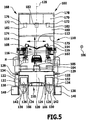
- Fig. 1 to 7 illustrated as a whole with 100 designated paint shop for painting workpieces, in particular of vehicle bodies 102, comprises a purely schematically illustrated conveyor 104, by means of which the vehicle bodies 102, which above a in Fig. 5 shown upper side 105 of the conveying device 104 can be arranged along a conveying direction 106 by an application area 108 of a designated as a whole by 110 paint booth can be moved.
- the conveyor 104 may be formed, for example, as an inverted circular conveyor or as an inverted monorail conveyor.
- the application area 108 is the interior of the painting booth 110, which is bounded on both sides of the conveyor 104 by a respective outer wall of the painting booth 110 designed as a booth wall 114 in a direction perpendicular to the conveying direction 106, which corresponds to the longitudinal direction of the painting booth 110.
- painting devices 116 designed as painting robots are arranged in the painting booth 110 (see FIG Fig. 2 . 3 . 5 and 6 ).
- a cleaning device designated as a whole 118 is arranged under the spray booth 110.
- the cleaning device 118 is used for separating wet paint overspray from an air stream, which is passed through the application area 108 of the paint booth 110 down into the cleaning device 118.
- the cleaning device 118 comprises a substantially cuboid filter chamber 120, which is bounded in the transverse direction 112 of the paint booth 110 by vertical side walls 122, which are substantially aligned with the side cabin walls 114 of the paint booth 110, so that the filter chamber 120 substantially the same extent in one to the conveying direction 106 has vertical and horizontal direction as the paint booth 110th
- the side walls 122 form the lateral outer walls of the filter chamber 120.
- a plurality, for example eight, filter devices 124 are arranged, in which regenerable surface filters are provided.
- the eight filter devices 124 are arranged in this embodiment in two rows of four filter devices 124, wherein the two rows are each aligned parallel to the conveying direction 106 and horizontally and with respect to a vertically and in the conveying direction 106 extending longitudinal center plane 128 of the painting booth 110 are arranged mirror-symmetrically to each other.
- an air supply device 129 is provided on both sides in this embodiment.
- an air curtain can be produced above the filter devices 124, which prevents settling of wet paint overspray on the upper side of the filter devices 124.
- a funnel-shaped receptacle 130 for receiving wet paint overspray and filter aid material, which is cleaned by the regenerable surface filters, is arranged in each case.
- each filter device 124 is bounded on its side facing away from the longitudinal center plane 128 of the paint booth 110 by a respective base body 134.
- the paint shop 100 in this embodiment comprises eight main body 134.
- Each main body 134 in this embodiment comprises a cleaning device, not shown in the drawings, for periodically cleaning wet-paint overspray particles and filter aid material (precoat material), which have been infiltrated on the surface filters of the filter devices 124.
- a cleaning device not shown in the drawings, for periodically cleaning wet-paint overspray particles and filter aid material (precoat material), which have been infiltrated on the surface filters of the filter devices 124.
- each main body 134 two vertical connecting channels 138 are arranged, which open into collecting channels 140 and allow fluid communication between the main bodies 134 and the collecting channels 140.
- two collecting channels 140 are provided, which extend below the main body 134 and the connecting channels 138 and are aligned parallel to the conveying direction 106.
- the collecting channels 140 are formed with respect to the longitudinal center plane 128 mirror-symmetrical to each other and arranged and spaced from each other. They each include one of the longitudinal center plane 128 of the painting booth 110 facing inside 142, which is further spaced from the longitudinal center plane 128 of the painting booth 110 as the outer walls 132 of the filter devices 124th
- the collecting channels 140 extend in a direction parallel to the conveying direction 106 substantially over the entire length of the painting booth 110 and have a taken in a direction perpendicular to the conveying direction 106 rectangular cross-section.
- a fan 148 arranged (see, in particular Fig. 7 ).
- a return line 150 is arranged in each case.
- Each of the return lines 150 includes an adapter element 152 and a rectilinear return section 154, wherein the rectilinear return section 154 of the return line 150 is in fluid communication with one of the fans 148 by way of the adapter element 152.
- the rectilinear return sections 154 of the two return lines 150 are aligned vertically and with respect to the longitudinal center plane 128 of the painting booth 110 mirror-symmetrical to each other and arranged and arranged spaced from each other.
- the rectilinear return sections 154 comprise mutually opposite inner sides 156 facing the longitudinal center plane 128 of the painting booth 110 and outer sides 158 facing away from the inner sides 156.
- the rectilinear return sections 154 have a rectangular cross-section taken in the horizontal direction.
- the rectilinear return sections 154 are arranged on the painting installation 100 such that the inner sides 156 of the rectilinear return sections 154 have a smaller distance from the longitudinal center plane 128 of the paint booth 110 than the cabin walls 114 of the paint booth 110 and the outer walls 132 of the filter devices 124.
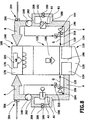
- the outer sides 158 of the rectilinear return sections 154 each have a distance D from the longitudinal center plane 128 of the spray booth 110, which is smaller than the sum of the distance d1 between a cabin wall 114 of the spray booth 110 and the longitudinal center plane 128 of the spray booth 110 and the distance d2 between the inner side 156 and the outer side 158 of the rectilinear return section 154 of the return line 150 (see FIG Fig. 6 and 7 ).
- the outer sides 158 of the rectilinear return sections 154 are aligned with the cabin walls 114 of the paint booth 110.
- the rectilinear return sections 154 of the return line 150 extend in the illustrated embodiment of a lower end 164 which is located approximately at the level of an upper edge 166 of the receptacle 130, vertically up to an upper end 160 which adjacent to a the paint booth 110 provided plenum 168 is arranged.
- the rectilinear return section 154 thus extends over a height h that is substantially greater than the distance H between a bottom 175 of a filter cover 174 and the top 105 of the conveyor 104 (see FIG Fig. 7 ).
- the rectilinear return sections 154 are in fluid communication with the air supply devices 129 to permit supply of circulating air from the rectilinear return sections 154 directly into the filter chamber 120.
- valves designed as blocking flaps 210 are provided (see FIG Fig. 8 ).
- the air supply devices 129 are on both sides of the filter chamber 120 with one (in the Fig. 1 to 7 not shown) supply air system 194 (see Fig. 8 ) in fluid communication.
- supply air system 194 To control the air supply devices 129 supplied from the supply air systems 194 supply air flow formed as supply air valves 196 valves.
- each rectilinear return section 154 At the upper end 160 of each rectilinear return section 154, a curved return section 162 is provided which is in fluid communication with the rectilinear return section 154.
- the plenum 168 includes a substantially cuboidal chamber 170 which extends in the conveying direction 106 over substantially the entire length of the painting booth 110 and is delimited in the transverse direction 112 of the painting booth 110 by vertical side walls 172 connected to the lateral cabin walls 114 of FIG Paint booth 110 are aligned so that the chamber 170 has substantially the same horizontal cross-sectional area as the paint booth 110.
- the side walls 172 form the lateral outer walls of the plenum 168.
- the chamber 170 of the plenum 168 is separated from the application area 108 of the paint booth 110 by means of the horizontally oriented filter cover 174, the horizontal underside 175 of the filter cover 174 facing the application area 108 of the paint booth 110.
- a false ceiling 176 in the plenum 168 which divides the chamber 170 of the plenum 168 into an upper area 178 and a lower area 180.
- a plurality, for example twenty-eight, safety filters 182 are arranged, which are used to remove any remaining in the air flow impurities in order to avoid any supply of contamination to the application area 108 of the paint booth 110.
- the curved return sections 162 are disposed in indentations 184 of the side walls 172 of the chamber 170 (see, in particular Fig. 1 ).
- the indentations 184 are aligned vertically and, for example, arranged on the workpiece inlet sides 144 of the painting booth 110 facing the ends of the side walls 172 of the chamber 170.
- openings 186 are provided, at which the curved return sections 162 open into the upper region 178 of the chamber 170 of the plenum 168.
- the indentations 184 extend over the entire height of the plenum 168 and over the entire height of the paint booth 110.
- the rectilinear return sections 154 of the return lines 150 run partially within the indentations 184 and thus, compared to an arrangement of the rectilinear return sections 154 outside the indentations 184, have a smaller distance from the longitudinal center plane 128 of the paint booth 110.
- the rectilinear return sections 154 extend at least partially both within an outer contour 111 of the paint booth 110 and within an outer contour 169 of the plenum 168 ( Fig. 7 ).
- the outer contour 111 of the spray booth 110 is the outer boundary of the space area which, when each cross section of the spray booth 110 taken perpendicular to the conveying direction 106 is moved along the conveying direction 106 to the ends of the spray booth 110, is swept by at least one of these cross sections.
- the outer contour thus defined always encloses a spatial region which is at least as large as the spatial region surrounded by the outer walls of the painting booth 110, but may also contain spatial regions lying outside the outer walls.
- An object can therefore be arranged outside the area of space surrounded by the outer walls and yet within the associated outer contour.
- the outer contour 169 of the plenum 168 is the outer boundary of the space area which, when each cross section of the plenum 168 taken perpendicular to the conveying direction 106 is moved along the conveying direction 106 to the ends of the painting booth 110, is swept by at least one of these cross sections.
- the rectilinear return sections 154 extend vertically downwardly into the region of the filter chamber 120 and therefore extend at least partially within an outer contour 121 of the filter chamber 120, in which embodiment the outer contour 121 of the filter chamber 120 is the outer boundary of the spatial region, if any taken perpendicular to the conveying direction 106 cross section of the filter chamber 120 along the conveying direction 106 is moved to the ends of the painting booth 110 is swept by at least one of these cross sections (see Fig. 6 and 7 ).
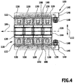
- two conditioning units 188 are provided in this embodiment, namely an air humidity conditioning unit 190 which is arranged in the collecting duct 140 on the left with respect to the conveying direction 106, and an air temperature conditioning unit 192 which is in the direction of conveyance 106 arranged right collecting duct 140 is arranged (see Fig. 4 ).
- Both the air humidity conditioning unit 190 and the air temperature conditioning unit 192 are arranged relative to the conveying direction 106 between two adjacent connecting channels 138, which connect the base bodies 134 to the collecting channels 140.
- the humidity regulating unit 190 is arranged relative to the conveying direction 106 between a second connecting channel 138 in the conveying direction 106 and a third connecting channel 138 of the eight in the conveying direction 106 in succession and with respect to the conveying direction 106 on the left arranged connecting channels 138.
- the air temperature conditioning unit 192 and the humidity control unit 190 are arranged mirror-symmetrically with respect to the longitudinal center plane 128 of the paint booth 110.
- the air temperature conditioning unit 192 is thus arranged relative to the conveying direction 106 between a second connecting channel 138 in the conveying direction 106 and a third connecting channel 138 of the eight in the conveying direction 106 in succession and with respect to the conveying direction 106 on the right arranged connecting channels 138.
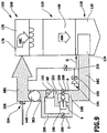
- the paint shop 100 described above works as follows (see in particular Fig. 7 ):
- a guided in the application area 108 of the paint booth 110 air flow is contaminated due to the painting of the painting 116 with wet paint overspray particles.
- the contaminated air stream is directed out of the paint booth 110 into the filter chamber 120 of the cleaning device 118.
- the air flow designated as the total air flow AB is split into a first partial air flow A and into a second partial air flow B.
- the first partial air flow A flows into the filter devices 124 arranged with respect to the conveying direction 106 to the left of the longitudinal center plane 128 of the painting booth 110.
- the second partial air flow B flows into the filter devices 124 arranged with respect to the conveying direction 106 to the right of the longitudinal center plane 128 of the painting booth 110.
- the filter devices 124 of the cleaning device 118 clean the air streams A and B from the wet paint overspray particles, with the cleaned air from the interior spaces 126 of the filter devices 124 entering the base bodies 134.
- the wet paint overspray particles and precoat particles infiltrated on the surface filters of the filter devices 124 are periodically cleaned of the surface filters and taken up in the receptacles 130.
- the cleaned air collected in the collecting ducts 140 is guided counter to the conveying direction 106 to the ends 146 of the collecting ducts 140 facing the workpiece inlet side 144 of the painting booth 110.
- the third connection channel 138 of the eight with respect to the conveying direction 106 left connection channels 138 is a Unterteilluftstrom A2, which by a first in the conveying direction 106 and second in the conveying direction 106 connecting channel 138 of the eight with respect to the conveying direction 106 left connection channels 138th flows, not conditioned.
- the arrangement of the conditioning units 188 in the collecting channels 140 causes the Unterteililluftströme A1 and A2 and the Unterteililluftströme B1 and B2 downstream of the respective conditioning unit 188, that is downstream of the humidity conditioning unit 190 and downstream of the Heiltemperaturkonditionieratti 192, merged again to the partial air streams A and B respectively become.
- the partial air streams A and B are passed through the blower 148 in the return lines 150 and guided within the rectilinear return sections 154 in the upper part of the paint shop 100.
- the partial air streams A and B guided in the return lines 150 are deflected and fed to the upper area 178 of the chamber 170 of the plenum 168.
- Both the safety filter 182 and the filter cover 174 further serve to equalize the air flow through the application area 108 of the paint booth 110 and the reduction of turbulence.
- a cross-flow Q of 900 m 3 / h with a temperature of 34 ° C and 42% humidity is added by the air supply devices 129 each.
- This transverse air flow Q can be supplied as circulating air via the barrier flaps 210 from the rectilinear return sections 154 or as supply air via the inlet flaps 196 from the supply air systems 194. It can also be provided that the cross-flow of air Q is mixed at partially open barrier flaps 210 and supply flaps 196 from circulating air and supply air.
- the partial air flows A and B are split into differently conditionable lower partial air flows A1, A2, B1 and B2.
- the divider air flow A1 of the partial air flow A is supplied to the humidity control unit 190.
- the sub-unit air flow A1 is humidified in this embodiment by the humidity control unit 190.
- the base air flow A2 is conducted past the humidity control unit 190 by means of a bypass line 208 and thus not conditioned.
- a valve designed as a bypass valve 200 may be provided in the flow path of the Unterteilil Kunststoffstroms A2, that is, in the bypass line 208.
- bypass flap 200 it is possible to regulate and / or control which portion of the partial air flow A is conditioned by means of the humidity control unit 190.
- a flow path merging 202 is provided downstream of the humidity control unit 190 (which is realized in the described embodiment by the junctions of the two connecting channels 138 adjacent to the blower 148 in the collecting duct 140 on the left with respect to the conveying direction 106).
- a blower 148 Downstream of the flow path merger 202, a blower 148 is arranged, which drives the partial air flow A.
- the blower fan 148 has an output of approximately 18.5 kW.
- an exhaust system 204 Downstream of the blower 148, an exhaust system 204 is arranged, wherein an exhaust air flow can be regulated by means of a designed as exhaust valve 206 valve.
- the discharged by means of the exhaust system 204 from the partial air flow A exhaust air flow is 900 m 3 / h.
- the divisional airflow B1 of the partial airflow B is supplied to the air temperature conditioning unit 192.
- the divider air flow B1 is cooled by the air temperature conditioning unit 192 in this embodiment.
- the divider air stream B2 is conducted past the air temperature conditioning unit 192 by means of a bypass line 208 and thus not conditioned.
- a valve designed as a bypass valve 200 may be provided in the flow path of the Unterteilil Kunststoffstroms B2, that is, in the bypass line 208.
- bypass flap 200 it is possible to regulate and / or control which portion of the partial air flow B is conditioned by means of the air temperature conditioning unit 192.
- a flow path merger 202 is provided downstream of the air temperature conditioning unit 192 (which in the embodiment described is realized by the junctions of the two connecting channels 138 adjacent to the blower 148 in the right-hand collecting duct 140 with respect to the conveying direction 106).
- a blower 148 Downstream of the flow path assembly 202, a blower 148 is arranged, which drives the partial air flow B.
- the blower fan 148 has an output of approximately 18.5 kW.
- an exhaust system 204 Downstream of the blower 148, an exhaust system 204 is arranged, wherein an exhaust air flow can be regulated by means of a designed as exhaust valve 206 valve.
- the discharged by means of the exhaust system 204 from the partial air flow B exhaust air flow is 900 m 3 / h.
- the partial air streams A and B are combined in the upper region 178 of the chamber 170 of the plenum 168 to the total air flow AB.
- the total air flow AB is then guided through the safety filter 182 arranged in the false ceiling 176 into the lower region 180 of the chamber 170 of the plenum 168 and from there through the filter cover 174 into the application region 108 of the paint booth 110.
- the air is thus at least partially guided in a circulating air circuit, that is to say that at least part of the air removed from the application area 108 of the paint booth 110 is returned to the application area 108 of the paint booth 110 after cleaning and conditioning.
- the air reaches a sinking speed of approximately 0.3 m / s with a total air flow AB of a total of 36,000 m 3 / h.
- FIG. 9 illustrated second embodiment of a device for supplying air to an application area of a paint shop differs from that in the Fig. 1 to 8 shown first embodiment in that an extraction of the total air flow AB in the filter chamber 120 of the paint system 100 is only one side.
- Only the partial air flow B is conditioned by means of a humidity conditioning unit 190.
- the partial air flow A is guided past the air humidity conditioning unit 190 by a bypass line 208 and combined at a flow path junction 202 with the air conditioned by the humidity control unit 190 of the partial air flow B to the partial air flow AB.
- the combined partial air flow AB is conditioned by means of the air temperature conditioning unit 192.
- the total air flow ABC is supplied by means of the blower 148 to the plenum 168.
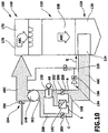
- An in Fig. 10 illustrated third embodiment of a device for supplying air to an application area of a paint shop differs from the in Fig. 9 illustrated second embodiment in that the humidity control unit 190 and the Heiltemperaturkonditionieriki 192 are arranged interchanged with each other.
- the partial air flow B is conditioned by means of the air temperature conditioning unit 192. After a merger of the so - called conditioned partial air flow B with the unconditioned partial air flow A is carried out a conditioning of the partial air flow AB by means of the humidity control unit 190th
- the in Fig. 10 illustrated third embodiment of the device for supplying air to an application area of a paint shop in terms of design and function with the in Fig. 9 illustrated second embodiment, to the above description in this respect reference is made.
- An in Fig. 11 illustrated fourth embodiment of a device for supplying air to an application area of a paint shop differs from the in Fig. 10 illustrated third embodiment in that the blower 148 is disposed not downstream of the flow path assembly 202, but upstream of the flow path branch 198, wherein at the Strömungswegzwezweigung 198 three partial air streams A, B and C branch off.
- the partial air flow A is conditioned by the humidity control unit 190.
- the partial airflow B is conditioned by means of the air temperature conditioning unit 192.
- the partial air flow C is not conditioned.
- the in Fig. 11 illustrated fourth embodiment of the device for supplying air to an application area of a paint shop in terms of design and function with the in Fig. 10 illustrated third embodiment, the above description of which reference is made.
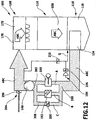
- An in Fig. 12 illustrated fifth embodiment of a device for supplying air to an application area of a paint shop differs from the in Fig. 11 4, in that the fan 148 is disposed not upstream of the flow path branch 198 but downstream of the flow path merger 202.
- an arrangement of the blower 148 downstream of a cooling device offers the advantage that the air flow is dehumidified more.
- the blower 148 is arranged upstream of a cooling device, the air flow is first heated and dehumidification is thus hindered, since the air heated by the blower 148 can absorb more moisture.
- the in Fig. 12 illustrated fifth embodiment of the device for supplying air to an application area of a paint shop in terms of design and function with the in Fig. 11 4, the above description of which is incorporated herein by reference.
- the division of a total air flow into partial air flows and the subsequent different conditioning of the partial air flows enable a particularly energy-efficient conditioning and supply of the air to be supplied to an application area of a paint shop.
Landscapes
- Details Or Accessories Of Spraying Plant Or Apparatus (AREA)
- Nozzles (AREA)
Claims (11)
- Dispositif d'amenée d'air dans une zone d'application (108) d'une installation de peinture (100), comportant un circuit de circulation d'air et au moins une unité de conditionnement (188) conditionnant au moins une partie de l'air guidé dans le circuit de circulation d'air,
le dispositif comprenant au moins une unité de conditionnement de l'humidité de l'air (190)
caractérisé en ce que,
le dispositif comprend plusieurs trajets d'écoulement différents pour au moins deux flux d'air partiels (A, B), les deux flux d'air partiels (A, B) ou plus pouvant être conditionnés différemment dans les différents trajets d'écoulement, pouvant être rassemblés et mélangés avant d'entrer dans la zone d'application (108) et pouvant être amenés par la suite en tant que flux d'air global mélangé (AB) à la zone d'application (108),
le dispositif comprenant au moins une soufflante (148) destinée à entraîner au moins un flux d'air partiel (A, B) guidé dans le circuit de circulation d'air, la soufflante (148) étant disposée en aval d'une unité de conditionnement de la température de l'air (192) du dispositif réalisée sous la forme d'un dispositif de refroidissement. - Dispositif selon la revendication 1, caractérisé en ce que le dispositif comprend au moins une unité de conditionnement de la température de l'air (192) destinée à agir sur la température d'au moins un courant d'air partiel (A, B).
- Dispositif selon la revendication 2, caractérisé en ce qu'au moins deux flux d'air partiels (A, B) peuvent être conditionnés au moyen d'au moins une unité de conditionnement (188), au moins un des flux d'air partiels (A, B) pouvant être humidifié.
- Dispositif selon l'une quelconque des revendications 1 à 3, caractérisé en ce que le dispositif comprend au moins une conduite de dérivation (208) au moyen de laquelle au moins un flux d'air partiel (A, B) peut être guidé devant au moins une unité de conditionnement (188) sans être conditionné par celle-ci.
- Dispositif selon l'une quelconque des revendications 1 à 4, caractérisé en ce que le dispositif comprend au moins une bifurcation de trajet d'écoulement (198) et au moins un ventilateur (148) destiné à entraîner au moins un flux d'air partiel (A, B) guidé dans le circuit de circulation d'air, le ventilateur (148) étant disposé en amont de la bifurcation de trajet d'écoulement (198).
- Dispositif selon l'une quelconque des revendications 1 à 5, caractérisé en ce que le dispositif comprend une installation d'air frais (194) destinée à amener de l'air frais au circuit de circulation d'air et une installation d'air vicié (204) destinée à évacuer l'air vicié du circuit de circulation d'air.
- Procédé de conditionnement d'un air destiné à être amené à une zone d'application (108) d'une installation de peinture (100), au moins une partie de l'air étant guidée dans un circuit de circulation d'air, un flux d'air global (AB) destiné à être amené à la zone d'application (108) en vue de son conditionnement étant divisé en au moins deux différents flux d'air partiels (A, B) conditionnés différemment, au moins une partie d'au moins un flux d'air partiel (A, B) étant conditionnée au moyen d'au moins une unité de conditionnement de l'humidité de l'air (190), caractérisé en ce que les deux flux d'air partiels (A, B) ou plus sont rassemblés et mélangés avant de pénétrer dans la zone d'application (108) de l'installation de peinture (100) puis amenés en tant que flux d'air global mélangé (AB) à la zone d'application (108),
au moins un flux d'air partiel (A, B) guidé dans le circuit de circulation d'air étant entraîné au moyen d'au moins une soufflante (148), laquelle est disposée en aval d'une unité de conditionnement de la température de l'air (192) réalisée sous la forme d'un dispositif de refroidissement. - Procédé selon la revendication 7, caractérisé en ce qu'au moins une partie d'au moins un flux d'air partiel (A, B) est conditionnée au moyen d'au moins une unité de conditionnement de la température de l'air (192).
- Procédé selon l'une quelconque des revendications 7 ou 8, caractérisé en ce que le rapport de l'air prélevé de la zone d'application (108) de l'installation de peinture (100) à l'air amené en sus atteint au moins 4:1.
- Procédé selon l'une quelconque des revendications 7 à 9, caractérisé en ce qu'au moins un flux d'air partiel (A, B) est guidé devant au moins une unité de conditionnement (188) sans être conditionné par celle-ci au moyen d'au moins une conduite de dérivation (208).
- Utilisation d'un dispositif selon l'une quelconque des revendications 1 à 6 destiné à mettre en oeuvre un procédé selon l'une quelconque des revendications 7 à 10.
Priority Applications (2)
| Application Number | Priority Date | Filing Date | Title |
|---|---|---|---|
| PL09716029T PL2244840T5 (pl) | 2008-02-29 | 2009-02-18 | Urządzenie do doprowadzania i sposób doprowadzania powietrza do obszaru aplikacji instalacji lakierniczej |
| EP13158416.1A EP2602027A3 (fr) | 2008-02-29 | 2009-02-18 | Dispositif et procédé d'acheminement d'air jusqu'à une zone d'application d'une installation de peinture |
Applications Claiming Priority (2)
| Application Number | Priority Date | Filing Date | Title |
|---|---|---|---|
| DE102008013714A DE102008013714A1 (de) | 2008-02-29 | 2008-02-29 | Vorrichtung und Verfahren zum Zuführen von Luft zu einem Applikationsbereich einer Lackieranlage |
| PCT/EP2009/001151 WO2009106255A1 (fr) | 2008-02-29 | 2009-02-18 | Procédé et dispositif d'amenée d'air dans une zone d'application d'une installation de peinture |
Related Child Applications (3)
| Application Number | Title | Priority Date | Filing Date |
|---|---|---|---|
| EP13158416.1A Division EP2602027A3 (fr) | 2008-02-29 | 2009-02-18 | Dispositif et procédé d'acheminement d'air jusqu'à une zone d'application d'une installation de peinture |
| EP13158416.1A Division-Into EP2602027A3 (fr) | 2008-02-29 | 2009-02-18 | Dispositif et procédé d'acheminement d'air jusqu'à une zone d'application d'une installation de peinture |
| EP13158416.1 Division-Into | 2013-03-08 |
Publications (3)
| Publication Number | Publication Date |
|---|---|
| EP2244840A1 EP2244840A1 (fr) | 2010-11-03 |
| EP2244840B1 EP2244840B1 (fr) | 2013-04-24 |
| EP2244840B2 true EP2244840B2 (fr) | 2016-07-27 |
Family
ID=40636995
Family Applications (2)
| Application Number | Title | Priority Date | Filing Date |
|---|---|---|---|
| EP13158416.1A Withdrawn EP2602027A3 (fr) | 2008-02-29 | 2009-02-18 | Dispositif et procédé d'acheminement d'air jusqu'à une zone d'application d'une installation de peinture |
| EP09716029.5A Active EP2244840B2 (fr) | 2008-02-29 | 2009-02-18 | Procede et dispositif d'amenee d'air dans une zone d'application d'une installation de peinture |
Family Applications Before (1)
| Application Number | Title | Priority Date | Filing Date |
|---|---|---|---|
| EP13158416.1A Withdrawn EP2602027A3 (fr) | 2008-02-29 | 2009-02-18 | Dispositif et procédé d'acheminement d'air jusqu'à une zone d'application d'une installation de peinture |
Country Status (10)
| Country | Link |
|---|---|
| EP (2) | EP2602027A3 (fr) |
| KR (1) | KR20100124728A (fr) |
| CN (1) | CN101959615B (fr) |
| BR (1) | BRPI0908902A2 (fr) |
| DE (1) | DE102008013714A1 (fr) |
| ES (1) | ES2422158T5 (fr) |
| MX (1) | MX2010009450A (fr) |
| PL (1) | PL2244840T5 (fr) |
| PT (1) | PT2244840E (fr) |
| WO (1) | WO2009106255A1 (fr) |
Families Citing this family (8)
| Publication number | Priority date | Publication date | Assignee | Title |
|---|---|---|---|---|
| DE102010030280A1 (de) | 2010-06-18 | 2011-12-22 | Dürr Systems GmbH | Lackieranlage mit Leitungssystem für das Umwälzen von Gas und/oder Luft |
| DE102010033711A1 (de) * | 2010-08-06 | 2012-02-09 | Eisenmann Ag | Im Umluftbetrieb arbeitende Lackieranlage |
| DE102011076469A1 (de) * | 2011-01-26 | 2012-07-26 | Dürr Systems GmbH | Oberflächenbehandlungsvorrichtung und Verfahren zum Betrieb einer Oberflächenbehandlungsvorrichtung |
| DE102015214706A1 (de) | 2015-07-31 | 2017-02-02 | Dürr Systems Ag | Behandlungsanlage und Verfahren zum Behandeln von Werkstücken |
| DE102015214711A1 (de) | 2015-07-31 | 2017-02-02 | Dürr Systems Ag | Behandlungsanlage und Verfahren zum Behandeln von Werkstücken |
| DE102016114466A1 (de) * | 2016-08-04 | 2018-02-08 | Eisenmann Se | Konditioniervorrichtung und Verfahren zum Konditionieren eines gasförmigen Mediums sowie Anlage und Verfahren zum Behandeln von Werkstücken |
| EP3618795A4 (fr) | 2017-05-05 | 2021-04-14 | Badri Amurthur | Procédés et appareil de stimulation |
| CN111774268A (zh) * | 2020-07-22 | 2020-10-16 | 顾丽霞 | 一种玻璃门用玻璃胶快速固化方法 |
Citations (2)
| Publication number | Priority date | Publication date | Assignee | Title |
|---|---|---|---|---|
| EP0595864B1 (fr) † | 1991-07-24 | 1995-05-17 | HERRMANN, Johannes | Cabine de laquage et de sechage |
| DE102006008431A1 (de) † | 2006-02-23 | 2007-08-30 | Rehau Ag + Co. | Lackieranlage mit einer Spritzkabine mit Abscheidesystem |
Family Cites Families (8)
| Publication number | Priority date | Publication date | Assignee | Title |
|---|---|---|---|---|
| GB1474732A (en) * | 1975-03-11 | 1977-05-25 | Carrier Drysys Ltd | Paint-spraying booths |
| JPS5858177A (ja) * | 1981-09-30 | 1983-04-06 | Toyota Central Res & Dev Lab Inc | 塗装ブ−ス |
| SE454328B (sv) * | 1982-04-30 | 1988-04-25 | Flaekt Ab | Forfarande och anordning for ventilering av en sprutbox |
| JPS58195675U (ja) * | 1982-06-17 | 1983-12-26 | トヨタ自動車株式会社 | 塗装ブ−ス |
| DE8327215U1 (de) * | 1983-09-22 | 1987-04-23 | RMG Beierling GmbH, 4791 Altenbeken | Lackier- und Abdunstanlage mit Umluftbelüftung |
| US5922130A (en) * | 1997-03-31 | 1999-07-13 | Sermatech International, Inc. | Spray booth for applying coatings to substrate |
| DE102007015150A1 (de) * | 2007-03-02 | 2008-09-04 | Wurster, Gerd | Lackieranlage |
| DE202007005748U1 (de) * | 2007-04-19 | 2007-11-22 | Teubner, Christian | Lackiereinrichtung |
-
2008
- 2008-02-29 DE DE102008013714A patent/DE102008013714A1/de not_active Withdrawn
-
2009
- 2009-02-18 WO PCT/EP2009/001151 patent/WO2009106255A1/fr not_active Ceased
- 2009-02-18 EP EP13158416.1A patent/EP2602027A3/fr not_active Withdrawn
- 2009-02-18 CN CN2009801069374A patent/CN101959615B/zh active Active
- 2009-02-18 BR BRPI0908902A patent/BRPI0908902A2/pt not_active Application Discontinuation
- 2009-02-18 PL PL09716029T patent/PL2244840T5/pl unknown
- 2009-02-18 ES ES09716029.5T patent/ES2422158T5/es active Active
- 2009-02-18 EP EP09716029.5A patent/EP2244840B2/fr active Active
- 2009-02-18 PT PT97160295T patent/PT2244840E/pt unknown
- 2009-02-18 KR KR1020107018738A patent/KR20100124728A/ko not_active Ceased
- 2009-02-18 MX MX2010009450A patent/MX2010009450A/es active IP Right Grant
Patent Citations (2)
| Publication number | Priority date | Publication date | Assignee | Title |
|---|---|---|---|---|
| EP0595864B1 (fr) † | 1991-07-24 | 1995-05-17 | HERRMANN, Johannes | Cabine de laquage et de sechage |
| DE102006008431A1 (de) † | 2006-02-23 | 2007-08-30 | Rehau Ag + Co. | Lackieranlage mit einer Spritzkabine mit Abscheidesystem |
Also Published As
| Publication number | Publication date |
|---|---|
| CN101959615A (zh) | 2011-01-26 |
| KR20100124728A (ko) | 2010-11-29 |
| EP2602027A3 (fr) | 2014-01-22 |
| PL2244840T3 (pl) | 2013-09-30 |
| ES2422158T5 (es) | 2017-02-10 |
| PT2244840E (pt) | 2013-05-06 |
| EP2602027A2 (fr) | 2013-06-12 |
| ES2422158T3 (es) | 2013-09-09 |
| EP2244840B1 (fr) | 2013-04-24 |
| EP2244840A1 (fr) | 2010-11-03 |
| BRPI0908902A2 (pt) | 2017-09-19 |
| MX2010009450A (es) | 2010-09-24 |
| DE102008013714A1 (de) | 2009-11-05 |
| CN101959615B (zh) | 2013-06-05 |
| PL2244840T5 (pl) | 2017-01-31 |
| WO2009106255A1 (fr) | 2009-09-03 |
Similar Documents
| Publication | Publication Date | Title |
|---|---|---|
| EP2244840B2 (fr) | Procede et dispositif d'amenee d'air dans une zone d'application d'une installation de peinture | |
| EP2258485B2 (fr) | Dispositif de séparation de pulvérisations de laque humide | |
| EP2244839B2 (fr) | Installation de peinture | |
| EP3712547A1 (fr) | Dispositif de mise en température destiné à la mise en température des objets | |
| EP2418431B1 (fr) | Dispositif de climatisation doté d'un dispositif de conditionnement de l'air | |
| EP3866985A1 (fr) | Installation de traitement et procédé de traitement | |
| DE202020103567U1 (de) | Behandlungsanlage | |
| DE102005013709A1 (de) | Vorrichtung zum Abtrennen von Naßlack-Overspray | |
| EP1704926B1 (fr) | Dispositif de séparation de l'excédent de peinture liquide | |
| EP0410098B1 (fr) | Système d'espace en construction modulaire pour un climat spécial | |
| DE102005013710A1 (de) | Vorrichtung zum Abtrennen von Naßlack-Overspray | |
| EP4025856A1 (fr) | Dispositif de séparation, installation de traitement, procédé de séparation de deux zones d'un espace et procédé de traitement de pièces | |
| DE19822537A1 (de) | Reinigungsvorrichtung für Karosserien von Fahrzeugen | |
| DE102020216427A1 (de) | Trennvorrichtung, Behandlungsanlage und Verfahren zum Behandeln von Werkstücken | |
| DE102004063654B4 (de) | Lackieranlage mit im Umluftverfahren betriebener Lackierkabine | |
| DE3832915A1 (de) | Reinraum | |
| CH699036B1 (de) | Farbspritzkabine. | |
| DE19958002A1 (de) | Belüftungsvorrichtung und Verfahren zur Belüftung eines Freiflächenarbeitsplatzes in einer Werkshalle | |
| DD298303A5 (de) | Modulares sonderklima-raumsystem |
Legal Events
| Date | Code | Title | Description |
|---|---|---|---|
| PUAI | Public reference made under article 153(3) epc to a published international application that has entered the european phase |
Free format text: ORIGINAL CODE: 0009012 |
|
| 17P | Request for examination filed |
Effective date: 20100727 |
|
| AK | Designated contracting states |
Kind code of ref document: A1 Designated state(s): AT BE BG CH CY CZ DE DK EE ES FI FR GB GR HR HU IE IS IT LI LT LU LV MC MK MT NL NO PL PT RO SE SI SK TR |
|
| AX | Request for extension of the european patent |
Extension state: AL BA RS |
|
| DAX | Request for extension of the european patent (deleted) | ||
| GRAP | Despatch of communication of intention to grant a patent |
Free format text: ORIGINAL CODE: EPIDOSNIGR1 |
|
| RIC1 | Information provided on ipc code assigned before grant |
Ipc: B05D 1/02 20060101ALN20121002BHEP Ipc: B05B 15/12 20060101AFI20121002BHEP Ipc: B05D 3/04 20060101ALN20121002BHEP |
|
| GRAS | Grant fee paid |
Free format text: ORIGINAL CODE: EPIDOSNIGR3 |
|
| GRAA | (expected) grant |
Free format text: ORIGINAL CODE: 0009210 |
|
| AK | Designated contracting states |
Kind code of ref document: B1 Designated state(s): AT BE BG CH CY CZ DE DK EE ES FI FR GB GR HR HU IE IS IT LI LT LU LV MC MK MT NL NO PL PT RO SE SI SK TR |
|
| REG | Reference to a national code |
Ref country code: GB Ref legal event code: FG4D Free format text: NOT ENGLISH |
|
| REG | Reference to a national code |
Ref country code: CH Ref legal event code: EP |
|
| REG | Reference to a national code |
Ref country code: PT Ref legal event code: SC4A Free format text: AVAILABILITY OF NATIONAL TRANSLATION Effective date: 20130426 |
|
| REG | Reference to a national code |
Ref country code: AT Ref legal event code: REF Ref document number: 608272 Country of ref document: AT Kind code of ref document: T Effective date: 20130515 |
|
| REG | Reference to a national code |
Ref country code: IE Ref legal event code: FG4D Free format text: LANGUAGE OF EP DOCUMENT: GERMAN |
|
| REG | Reference to a national code |
Ref country code: NL Ref legal event code: T3 |
|
| REG | Reference to a national code |
Ref country code: DE Ref legal event code: R096 Ref document number: 502009006936 Country of ref document: DE Effective date: 20130620 |
|
| REG | Reference to a national code |
Ref country code: RO Ref legal event code: EPE |
|
| REG | Reference to a national code |
Ref country code: ES Ref legal event code: FG2A Ref document number: 2422158 Country of ref document: ES Kind code of ref document: T3 Effective date: 20130909 |
|
| REG | Reference to a national code |
Ref country code: LT Ref legal event code: MG4D |
|
| REG | Reference to a national code |
Ref country code: PL Ref legal event code: T3 |
|
| REG | Reference to a national code |
Ref country code: SK Ref legal event code: T3 Ref document number: E 14411 Country of ref document: SK |
|
| REG | Reference to a national code |
Ref country code: HU Ref legal event code: AG4A Ref document number: E016919 Country of ref document: HU |
|
| PG25 | Lapsed in a contracting state [announced via postgrant information from national office to epo] |
Ref country code: GR Free format text: LAPSE BECAUSE OF FAILURE TO SUBMIT A TRANSLATION OF THE DESCRIPTION OR TO PAY THE FEE WITHIN THE PRESCRIBED TIME-LIMIT Effective date: 20130725 Ref country code: SI Free format text: LAPSE BECAUSE OF FAILURE TO SUBMIT A TRANSLATION OF THE DESCRIPTION OR TO PAY THE FEE WITHIN THE PRESCRIBED TIME-LIMIT Effective date: 20130424 Ref country code: NO Free format text: LAPSE BECAUSE OF FAILURE TO SUBMIT A TRANSLATION OF THE DESCRIPTION OR TO PAY THE FEE WITHIN THE PRESCRIBED TIME-LIMIT Effective date: 20130724 Ref country code: SE Free format text: LAPSE BECAUSE OF FAILURE TO SUBMIT A TRANSLATION OF THE DESCRIPTION OR TO PAY THE FEE WITHIN THE PRESCRIBED TIME-LIMIT Effective date: 20130424 Ref country code: IS Free format text: LAPSE BECAUSE OF FAILURE TO SUBMIT A TRANSLATION OF THE DESCRIPTION OR TO PAY THE FEE WITHIN THE PRESCRIBED TIME-LIMIT Effective date: 20130824 Ref country code: LT Free format text: LAPSE BECAUSE OF FAILURE TO SUBMIT A TRANSLATION OF THE DESCRIPTION OR TO PAY THE FEE WITHIN THE PRESCRIBED TIME-LIMIT Effective date: 20130424 |
|
| PG25 | Lapsed in a contracting state [announced via postgrant information from national office to epo] |
Ref country code: CY Free format text: LAPSE BECAUSE OF FAILURE TO SUBMIT A TRANSLATION OF THE DESCRIPTION OR TO PAY THE FEE WITHIN THE PRESCRIBED TIME-LIMIT Effective date: 20130424 Ref country code: HR Free format text: LAPSE BECAUSE OF FAILURE TO SUBMIT A TRANSLATION OF THE DESCRIPTION OR TO PAY THE FEE WITHIN THE PRESCRIBED TIME-LIMIT Effective date: 20130424 Ref country code: BG Free format text: LAPSE BECAUSE OF FAILURE TO SUBMIT A TRANSLATION OF THE DESCRIPTION OR TO PAY THE FEE WITHIN THE PRESCRIBED TIME-LIMIT Effective date: 20130724 Ref country code: LV Free format text: LAPSE BECAUSE OF FAILURE TO SUBMIT A TRANSLATION OF THE DESCRIPTION OR TO PAY THE FEE WITHIN THE PRESCRIBED TIME-LIMIT Effective date: 20130424 |
|
| PLBI | Opposition filed |
Free format text: ORIGINAL CODE: 0009260 |
|
| PG25 | Lapsed in a contracting state [announced via postgrant information from national office to epo] |
Ref country code: EE Free format text: LAPSE BECAUSE OF FAILURE TO SUBMIT A TRANSLATION OF THE DESCRIPTION OR TO PAY THE FEE WITHIN THE PRESCRIBED TIME-LIMIT Effective date: 20130424 Ref country code: DK Free format text: LAPSE BECAUSE OF FAILURE TO SUBMIT A TRANSLATION OF THE DESCRIPTION OR TO PAY THE FEE WITHIN THE PRESCRIBED TIME-LIMIT Effective date: 20130424 |
|
| 26 | Opposition filed |
Opponent name: EISENMANN AG Effective date: 20140121 |
|
| PLAX | Notice of opposition and request to file observation + time limit sent |
Free format text: ORIGINAL CODE: EPIDOSNOBS2 |
|
| REG | Reference to a national code |
Ref country code: DE Ref legal event code: R026 Ref document number: 502009006936 Country of ref document: DE Effective date: 20140121 |
|
| PLAF | Information modified related to communication of a notice of opposition and request to file observations + time limit |
Free format text: ORIGINAL CODE: EPIDOSCOBS2 |
|
| BERE | Be: lapsed |
Owner name: DURR SYSTEMS G.M.B.H. Effective date: 20140228 |
|
| PLBB | Reply of patent proprietor to notice(s) of opposition received |
Free format text: ORIGINAL CODE: EPIDOSNOBS3 |
|
| PG25 | Lapsed in a contracting state [announced via postgrant information from national office to epo] |
Ref country code: LU Free format text: LAPSE BECAUSE OF FAILURE TO SUBMIT A TRANSLATION OF THE DESCRIPTION OR TO PAY THE FEE WITHIN THE PRESCRIBED TIME-LIMIT Effective date: 20140218 |
|
| REG | Reference to a national code |
Ref country code: CH Ref legal event code: PL |
|
| PG25 | Lapsed in a contracting state [announced via postgrant information from national office to epo] |
Ref country code: LI Free format text: LAPSE BECAUSE OF NON-PAYMENT OF DUE FEES Effective date: 20140228 Ref country code: CH Free format text: LAPSE BECAUSE OF NON-PAYMENT OF DUE FEES Effective date: 20140228 |
|
| REG | Reference to a national code |
Ref country code: IE Ref legal event code: MM4A |
|
| PG25 | Lapsed in a contracting state [announced via postgrant information from national office to epo] |
Ref country code: IE Free format text: LAPSE BECAUSE OF NON-PAYMENT OF DUE FEES Effective date: 20140218 Ref country code: BE Free format text: LAPSE BECAUSE OF NON-PAYMENT OF DUE FEES Effective date: 20140228 |
|
| REG | Reference to a national code |
Ref country code: FR Ref legal event code: PLFP Year of fee payment: 7 |
|
| REG | Reference to a national code |
Ref country code: DE Ref legal event code: R082 Ref document number: 502009006936 Country of ref document: DE Representative=s name: HOEGER, STELLRECHT & PARTNER PATENTANWAELTE MB, DE |
|
| RIC2 | Information provided on ipc code assigned after grant |
Ipc: B05B 15/12 20060101AFI20151110BHEP Ipc: B05D 1/02 20060101ALN20151110BHEP Ipc: B05D 3/04 20060101ALN20151110BHEP |
|
| REG | Reference to a national code |
Ref country code: FR Ref legal event code: PLFP Year of fee payment: 8 |
|
| PG25 | Lapsed in a contracting state [announced via postgrant information from national office to epo] |
Ref country code: MT Free format text: LAPSE BECAUSE OF FAILURE TO SUBMIT A TRANSLATION OF THE DESCRIPTION OR TO PAY THE FEE WITHIN THE PRESCRIBED TIME-LIMIT Effective date: 20130424 |
|
| PUAH | Patent maintained in amended form |
Free format text: ORIGINAL CODE: 0009272 |
|
| STAA | Information on the status of an ep patent application or granted ep patent |
Free format text: STATUS: PATENT MAINTAINED AS AMENDED |
|
| 27A | Patent maintained in amended form |
Effective date: 20160727 |
|
| AK | Designated contracting states |
Kind code of ref document: B2 Designated state(s): AT BE BG CH CY CZ DE DK EE ES FI FR GB GR HR HU IE IS IT LI LT LU LV MC MK MT NL NO PL PT RO SE SI SK TR |
|
| REG | Reference to a national code |
Ref country code: DE Ref legal event code: R102 Ref document number: 502009006936 Country of ref document: DE |
|
| REG | Reference to a national code |
Ref country code: NL Ref legal event code: FP |
|
| REG | Reference to a national code |
Ref country code: DE Ref legal event code: R081 Ref document number: 502009006936 Country of ref document: DE Owner name: DUERR SYSTEMS AG, DE Free format text: FORMER OWNER: DUERR SYSTEMS GMBH, 74321 BIETIGHEIM-BISSINGEN, DE Ref country code: DE Ref legal event code: R082 Ref document number: 502009006936 Country of ref document: DE Representative=s name: HOEGER, STELLRECHT & PARTNER PATENTANWAELTE MB, DE |
|
| REG | Reference to a national code |
Ref country code: SK Ref legal event code: T5 Ref document number: E 14411 Country of ref document: SK |
|
| REG | Reference to a national code |
Ref country code: ES Ref legal event code: DC2A Ref document number: 2422158 Country of ref document: ES Kind code of ref document: T5 Effective date: 20170210 |
|
| REG | Reference to a national code |
Ref country code: FR Ref legal event code: PLFP Year of fee payment: 9 |
|
| REG | Reference to a national code |
Ref country code: DE Ref legal event code: R079 Ref document number: 502009006936 Country of ref document: DE Free format text: PREVIOUS MAIN CLASS: B05B0015120000 Ipc: B05B0016000000 |
|
| REG | Reference to a national code |
Ref country code: FR Ref legal event code: PLFP Year of fee payment: 10 |
|
| PGFP | Annual fee paid to national office [announced via postgrant information from national office to epo] |
Ref country code: MC Payment date: 20180214 Year of fee payment: 10 Ref country code: TR Payment date: 20180216 Year of fee payment: 10 |
|
| PG25 | Lapsed in a contracting state [announced via postgrant information from national office to epo] |
Ref country code: MK Free format text: LAPSE BECAUSE OF FAILURE TO SUBMIT A TRANSLATION OF THE DESCRIPTION OR TO PAY THE FEE WITHIN THE PRESCRIBED TIME-LIMIT Effective date: 20130424 |
|
| REG | Reference to a national code |
Ref country code: DE Ref legal event code: R082 Ref document number: 502009006936 Country of ref document: DE Representative=s name: DTS PATENT- UND RECHTSANWAELTE SCHNEKENBUEHL U, DE Ref country code: DE Ref legal event code: R082 Ref document number: 502009006936 Country of ref document: DE Representative=s name: HOEGER, STELLRECHT & PARTNER PATENTANWAELTE MB, DE |
|
| PG25 | Lapsed in a contracting state [announced via postgrant information from national office to epo] |
Ref country code: MC Free format text: LAPSE BECAUSE OF NON-PAYMENT OF DUE FEES Effective date: 20190228 |
|
| PGFP | Annual fee paid to national office [announced via postgrant information from national office to epo] |
Ref country code: FI Payment date: 20210218 Year of fee payment: 13 Ref country code: PT Payment date: 20210204 Year of fee payment: 13 Ref country code: RO Payment date: 20210204 Year of fee payment: 13 Ref country code: NL Payment date: 20210217 Year of fee payment: 13 |
|
| PGFP | Annual fee paid to national office [announced via postgrant information from national office to epo] |
Ref country code: AT Payment date: 20210218 Year of fee payment: 13 |
|
| REG | Reference to a national code |
Ref country code: DE Ref legal event code: R082 Ref document number: 502009006936 Country of ref document: DE Representative=s name: DTS PATENT- UND RECHTSANWAELTE SCHNEKENBUEHL U, DE Ref country code: DE Ref legal event code: R082 Ref document number: 502009006936 Country of ref document: DE Representative=s name: DTS PATENT- UND RECHTSANWAELTE PARTMBB, DE |
|
| REG | Reference to a national code |
Ref country code: FI Ref legal event code: MAE |
|
| REG | Reference to a national code |
Ref country code: NL Ref legal event code: MM Effective date: 20220301 |
|
| REG | Reference to a national code |
Ref country code: AT Ref legal event code: MM01 Ref document number: 608272 Country of ref document: AT Kind code of ref document: T Effective date: 20220218 |
|
| PG25 | Lapsed in a contracting state [announced via postgrant information from national office to epo] |
Ref country code: RO Free format text: LAPSE BECAUSE OF NON-PAYMENT OF DUE FEES Effective date: 20220218 Ref country code: PT Free format text: LAPSE BECAUSE OF NON-PAYMENT OF DUE FEES Effective date: 20220818 Ref country code: FI Free format text: LAPSE BECAUSE OF NON-PAYMENT OF DUE FEES Effective date: 20220218 Ref country code: AT Free format text: LAPSE BECAUSE OF NON-PAYMENT OF DUE FEES Effective date: 20220218 |
|
| PG25 | Lapsed in a contracting state [announced via postgrant information from national office to epo] |
Ref country code: NL Free format text: LAPSE BECAUSE OF NON-PAYMENT OF DUE FEES Effective date: 20220301 |
|
| P01 | Opt-out of the competence of the unified patent court (upc) registered |
Effective date: 20230628 |
|
| PG25 | Lapsed in a contracting state [announced via postgrant information from national office to epo] |
Ref country code: TR Free format text: LAPSE BECAUSE OF NON-PAYMENT OF DUE FEES Effective date: 20190218 |
|
| PGFP | Annual fee paid to national office [announced via postgrant information from national office to epo] |
Ref country code: HU Payment date: 20250220 Year of fee payment: 17 |
|
| PGFP | Annual fee paid to national office [announced via postgrant information from national office to epo] |
Ref country code: DE Payment date: 20250218 Year of fee payment: 17 |
|
| PGFP | Annual fee paid to national office [announced via postgrant information from national office to epo] |
Ref country code: FR Payment date: 20250221 Year of fee payment: 17 Ref country code: CZ Payment date: 20250212 Year of fee payment: 17 |
|
| PGFP | Annual fee paid to national office [announced via postgrant information from national office to epo] |
Ref country code: IT Payment date: 20250221 Year of fee payment: 17 Ref country code: SK Payment date: 20250211 Year of fee payment: 17 Ref country code: GB Payment date: 20250219 Year of fee payment: 17 |
|
| PGFP | Annual fee paid to national office [announced via postgrant information from national office to epo] |
Ref country code: PL Payment date: 20250207 Year of fee payment: 17 |
|
| PGFP | Annual fee paid to national office [announced via postgrant information from national office to epo] |
Ref country code: ES Payment date: 20250331 Year of fee payment: 17 |