EP2244580B1 - Vorrichtung und verfahren zum trennen von oberflächenschichten bei produkten der nahrungsmittelindustrie - Google Patents
Vorrichtung und verfahren zum trennen von oberflächenschichten bei produkten der nahrungsmittelindustrie Download PDFInfo
- Publication number
- EP2244580B1 EP2244580B1 EP09710041.6A EP09710041A EP2244580B1 EP 2244580 B1 EP2244580 B1 EP 2244580B1 EP 09710041 A EP09710041 A EP 09710041A EP 2244580 B1 EP2244580 B1 EP 2244580B1
- Authority
- EP
- European Patent Office
- Prior art keywords
- separating
- transport
- product
- gap
- deflecting
- Prior art date
- Legal status (The legal status is an assumption and is not a legal conclusion. Google has not performed a legal analysis and makes no representation as to the accuracy of the status listed.)
- Active
Links
Images

Classifications
-
- A—HUMAN NECESSITIES
- A22—BUTCHERING; MEAT TREATMENT; PROCESSING POULTRY OR FISH
- A22C—PROCESSING MEAT, POULTRY, OR FISH
- A22C25/00—Processing fish ; Curing of fish; Stunning of fish by electric current; Investigating fish by optical means
- A22C25/17—Skinning fish
-
- A—HUMAN NECESSITIES
- A22—BUTCHERING; MEAT TREATMENT; PROCESSING POULTRY OR FISH
- A22B—SLAUGHTERING
- A22B5/00—Accessories for use during or after slaughtering
- A22B5/16—Skinning instruments or knives
- A22B5/166—Drum skinners
-
- Y—GENERAL TAGGING OF NEW TECHNOLOGICAL DEVELOPMENTS; GENERAL TAGGING OF CROSS-SECTIONAL TECHNOLOGIES SPANNING OVER SEVERAL SECTIONS OF THE IPC; TECHNICAL SUBJECTS COVERED BY FORMER USPC CROSS-REFERENCE ART COLLECTIONS [XRACs] AND DIGESTS
- Y10—TECHNICAL SUBJECTS COVERED BY FORMER USPC
- Y10T—TECHNICAL SUBJECTS COVERED BY FORMER US CLASSIFICATION
- Y10T83/00—Cutting
- Y10T83/04—Processes
Definitions
- the invention relates to a device for separating surface layers in products of the food industry, comprising a transport element for transporting the products from an inlet region to an outlet region, wherein the transport element is guided at least in the outlet region to a substantially cylindrically shaped deflecting element, a pressing element for pressing the products to the transport element and a separating element for separating the surface layer from the product, wherein the separating element is arranged to form a separating gap between the separating element and the transport element in the outlet region of the transport element.
- the invention further relates to a method for removing surface layers in products of the food industry, comprising the steps of: transporting the product to be processed by means of a transport element from an inlet region into an outlet region, feeding the product into a separating gap which is located between a separating element located in the outlet region and the transport element is formed, pressing the product to be processed by means of a pressure element to the transport element during the separation process, and separating a surface layer by means of the arranged in the outlet region of the transport element separating element.
- a generic device or a generic method is off WO 02/078453 known.
- Such devices and methods are used in the food industry and especially in the fish processing industry.
- the separation of the skin and / or fat layer from the fillet can be done in one or more consecutive cuts Separations done.
- the separating elements for separating the surface layer are usually rectilinear. This means that between the separating element and the transport element or the deflecting element located in the region of the separating element, which serves as a kind of cutting counter, there results a separating gap which remains the same over the entire width of the transport element. This results in that the surface layer to be separated has the same thickness over the entire width.
- the salmon in the mainbone area has a thicker layer of fat than in areas remote from the mainbone. Also, the thickness and width of the fat layer in the longitudinal direction of the fillet changes.
- a device in which a conveyor belt serves as a support surface for the products.
- This conveyor belt is associated with an adjustable support with an adjustable profile transverse to the transport direction of the products.
- the support lies below the conveyor belt and comprises liftable and lowerable elements which are arranged side by side transversely to the transport direction for producing the profile forming a process gap.
- this device has the disadvantage that it requires a lot of control effort.
- the structural design is very complex and therefore expensive. It is therefore an object of the present invention to provide a simple and easy to handle device which ensures a variable process gap in addition to the separation gap. Furthermore, it is an object of the invention to propose a corresponding method.
- the deflection element arranged in the outlet region is designed to exercise a rotational movement and can be controlled accordingly and has an alternating in the axial direction and / or circumferential direction to form a process gap cross-sectional shape.
- the changing shape or shape of the deflecting element on the side facing the separating element on the one hand and the controllability of the deflecting element on the other hand make it possible for the process gap to be variable, so that product-specific separating processes can be realized.
- An expedient development of the invention is characterized in that the deflecting element is concave in section at least in sections.
- the process gap may be formed at least partially larger or deeper, so that e.g. In the area of the main bone, more fat can be removed than in the margins of a fillet.
- the concave configuration of the lateral surface of the deflecting element varies both in the axial direction and in the circumferential direction in the width and / or depth.
- the axial direction denotes the direction transverse to the transport direction of the products.
- the circumferential direction describes the direction of rotation of the deflecting element.
- a preferred embodiment of the invention is characterized in that the deflecting element can be controlled during the separation process to change the process gap. By turning the deflecting element, the process gap can be selectively changed, from product to product or during the processing of a product.
- the object is achieved by a method with the steps mentioned above in that the deflecting element is driven to exercise a rotational movement, so that in addition to the separating gap, a variable process gap is formed.
- the device shown in the figures serves to separate a fatty layer of fillets of the species salmon.
- the device is also suitable for processing / processing other products and in particular also for separating other surface layers, such as e.g. Skin layers or the like suitable and usable.
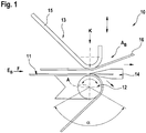
- Substantially illustrated device 10 for separating skin layers and / or fat layers of fish fillets comprises a transport element 11.
- the transport element 11 is preferably designed as an endless circulating and flexible conveyor belt or the like. Other embodiments of the transport element 11, for example as a suction belt, flexible conveyor chain or the like, are also possible.
- the transport element 11 is guided around a plurality of drive and / or deflection elements, in particular also around a substantially cylindrically configured deflecting element 12.
- the products to be processed are conveyed in the conveying direction F by a Feeding area E B transported to a discharge area A B. In the outlet area A B of the transport element 11, the cylindrical deflecting element 12 is arranged.
- the device 10 comprises a pressing element 13 for pressing the products against the transport element 11 and a separating element 14 for separating the surface layer from the product.
- the separating element 14 is likewise arranged in the outlet region A B of the transport element 11 and forms a separating gap between itself and the transport element 11.
- the separating element 14 is designed to be movable.
- the pressing member 13 is also adjustable, and preferably in the vertical direction to the conveying plane for changing the distance to the transport element 11.
- the pressing member 13 is preferably made of a Andrückfinger 15 and a guide belt 16 or the like.
- the pressure element 13 which may also have any other conventional design, extends at least over the product width, but preferably over the entire width of the transport element 11. With respect to the deflection element 12, which will be described in detail below, the pressure element 13 is directly above the deflecting element 12. Preferably, the pressing element 13 is arranged such that the pressing force K is directed perpendicular to the axis A of the deflecting element 12.
- the pressing element 13 can also be designed as a guide element and / or serve as a guide. In further embodiments not shown, the pressing element 13 may also be assigned a guide element which lies in the conveying direction F in front of the pressing element 13 and may have different configurations. In particular, the guide element can be adapted to the contour of the products and designed or arranged in a cascade.
- the arranged in the outlet region A B of the transport element 11 deflecting element 12 is formed at least partially movable.
- the deflecting element 12 is designed to exercise a rotational movement and controlled accordingly.
- the cylindrical deflecting element 12 is rotatable about an axis A.
- the rotation about the axis A for example, in a defined and limited by stops or the like angle range ⁇ or circumferentially.
- a process gap is formed or defined in addition to the separating gap, which ensures an individual and in particular also variable cutting guide.
- the process gap can be changed both in the width, ie transversely to the conveying direction F, as well as in the depth, that is, vertically to the conveying plane separately from the separating gap or independently thereof.
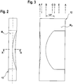
- the deflecting element 12 is at least partially concave in the region of its lateral surface M F.
- the recess formed in the lateral surface M F can also assume other shapes and forms.
- the concave configuration of the lateral surface M F of the deflecting element 12 varies both in the axial direction and in the circumferential direction in the width and / or depth, as in particular from the FIGS. 2 to 4 becomes clear.
- the concave recess preferably extends over part of the width of the deflecting element 12 (see FIGS. 2 and 3 ).
- the recess may also extend over the entire width. Also in the circumferential direction, the recess is only partially formed (see FIG. 4 ). An education of the recess over the entire circumference is also possible.
- the deflection element 12 is (on) controllable, such that optionally during a separating cut on a product or between parting cuts from product to product by rotation of the deflecting element 12, a different contour serves as a counter-position to the separating element 14, so that the cutting guide changes.
- the process gap can be changed continuously or intermittently.
- the formation of the deflecting element 12 is particularly clear.
- the section between levels B and D corresponds to FIG. 3 is shown as unwound lateral surface M F , the peripheral portion BD of 120 ° in FIG. 4 ,
- the FIG. 5 are illustrative in FIG. 4 indicated sections CA, EB, AC, FD and BE darqterrorism.
- the apparatus 10 may further include means (not shown) for detecting the deflecting element 12 for detecting geometric data and / or image data Be assigned to products.
- the device 10 comprises a control means (likewise not illustrated).
- the control means may be designed and arranged to control the deflecting element 12 and / or the separating element 14. Control means and means for detecting the geometric data and / or image data are operatively connected to each other.
- the transport element 11 is particularly suitable for a so-called pinch drive.
- Other conventional drives are also used.
- the separating element 14 may be a band knife, an oscillating knife or any other suitable cutting and / or separating means.
- the pressure element 15 is preferably adapted to the product side facing the contour of the respective product. Level or curved or otherwise shaped formations are also used.
- the deflecting element 12 may also be a profiled and pivotable deflecting edge or the like in non-illustrated embodiments.
- a first product is conveyed from the inlet region E B by means of the transport element 11 to the outlet region A B.
- the separating element 14 is adjusted to form a separating gap relative to the transport element 11.
- the product runs on the transport element 11 lying under the pressure element 13, which presses the product with a preferably defined force against the transport element 11.
- the product is conveyed against the knife or cutting edge of the fixed, rotating or oscillating separating element 14.
- the pressing member 13 presses the product with a pressing force F on the transport element 11, whereby the flexible transport element 11 and thus also the product conforms to the contour of the arranged below a run of the transport element 11 deflecting element 12.
- the surface layer so for example a skin and / or fat layer is separated from the fillet.
- the separated surface layer is discharged obliquely downward between the separating element 14 and the transport element 11, while the filet is discharged obliquely upward between the separating element 14 and the guide belt 15 of the pressing element 13.
- the cutting guide can be varied during the separation process by the deflection element 12 is rotated counterclockwise or clockwise, so that the separating element 14 is opposite to a modified contour as a counter-position.
- the control of the deflector 12 may be e.g. even after a product change, so that an adaptation of the process gap is product-specific.
Landscapes
- Life Sciences & Earth Sciences (AREA)
- Engineering & Computer Science (AREA)
- Food Science & Technology (AREA)
- Wood Science & Technology (AREA)
- Zoology (AREA)
- Meat, Egg Or Seafood Products (AREA)
- Processing Of Meat And Fish (AREA)
- Branching, Merging, And Special Transfer Between Conveyors (AREA)
Priority Applications (1)
| Application Number | Priority Date | Filing Date | Title |
|---|---|---|---|
| PL09710041T PL2244580T3 (pl) | 2008-02-15 | 2009-02-04 | Urządzenie i sposób do oddzielania warstw powierzchniowych w produktach przemysłu spożywczego |
Applications Claiming Priority (2)
| Application Number | Priority Date | Filing Date | Title |
|---|---|---|---|
| DE200810009922 DE102008009922B4 (de) | 2008-02-15 | 2008-02-15 | Vorrichtung und Verfahren zum Trennen von Oberflächenschichten bei Produkten der Nahrungsmittelindustrie |
| PCT/EP2009/000999 WO2009100912A1 (de) | 2008-02-15 | 2009-02-04 | Vorrichtung und verfahren zum trennen von oberflächenschichten bei produkten der nahrungsmittelindustrie |
Publications (2)
| Publication Number | Publication Date |
|---|---|
| EP2244580A1 EP2244580A1 (de) | 2010-11-03 |
| EP2244580B1 true EP2244580B1 (de) | 2017-01-18 |
Family
ID=40521911
Family Applications (1)
| Application Number | Title | Priority Date | Filing Date |
|---|---|---|---|
| EP09710041.6A Active EP2244580B1 (de) | 2008-02-15 | 2009-02-04 | Vorrichtung und verfahren zum trennen von oberflächenschichten bei produkten der nahrungsmittelindustrie |
Country Status (8)
| Country | Link |
|---|---|
| US (1) | US8246427B2 (pl) |
| EP (1) | EP2244580B1 (pl) |
| CA (1) | CA2714571C (pl) |
| CL (1) | CL2009000344A1 (pl) |
| DE (1) | DE102008009922B4 (pl) |
| DK (1) | DK2244580T3 (pl) |
| PL (1) | PL2244580T3 (pl) |
| WO (1) | WO2009100912A1 (pl) |
Families Citing this family (4)
| Publication number | Priority date | Publication date | Assignee | Title |
|---|---|---|---|---|
| BR112014023228B1 (pt) * | 2012-03-26 | 2019-11-26 | Mars Inc | moldagem rotativa ultrassônica |
| WO2013164861A1 (en) * | 2012-05-04 | 2013-11-07 | Skaginn Hf. | Device and method for skinning food products |
| US9752079B2 (en) | 2014-10-14 | 2017-09-05 | Exxonmobil Upstream Research Company | Electrostatic filtration of fine solids from bitumen |
| US11807472B2 (en) * | 2020-11-16 | 2023-11-07 | Prime Equipment Group, Llc | Product transfer roller |
Family Cites Families (12)
| Publication number | Priority date | Publication date | Assignee | Title |
|---|---|---|---|---|
| US2645812A (en) * | 1947-05-02 | 1953-07-21 | Frederick H Jensen | Fish fillet splitting and skinning machine |
| US3249139A (en) * | 1962-11-13 | 1966-05-03 | Wolverine Shoe & Tanning Corp | Skinning machine having automatic blade pitch control |
| US5591076A (en) * | 1995-04-21 | 1997-01-07 | Nordischer Maschinenbau Rud. Baader Gmbh & Co Kg | Apparatus for processing flat fish |
| NL1007704C1 (nl) * | 1997-12-05 | 1999-06-08 | Fieret Handelsonderneming C V | Visonthuidmachine. |
| DE19834524A1 (de) * | 1998-07-31 | 2000-02-10 | Nordischer Maschinenbau | Vorrichtung bzw. Verfahren zur Verarbeitung von Fleisch |
| DE19834866A1 (de) | 1998-08-01 | 2000-02-10 | Nordischer Maschinenbau | Vorrichtung zum Abtragen einer Oberflächenschicht von tierischem Muskelgewebe |
| US6129625A (en) * | 1999-08-26 | 2000-10-10 | Townsend Engineering Company | Method of trimming a meat portion by ultrasonic and electronic analysis |
| DE10027242A1 (de) | 2000-05-31 | 2001-12-06 | Biforce Anstalt Vaduz | Vorrichtung zum Enthäuten von Fischen |
| DK174906B1 (da) * | 2001-02-07 | 2004-02-16 | Joergin Bech | Fiskeafskindingsapparat og -fremgangsmåde. |
| DE10117304A1 (de) | 2001-03-31 | 2002-10-10 | Nordischer Maschinenbau | Verfahren und Vorrichtung zum Bearbeiten von Fischfilets |
| AT5839U3 (de) * | 2002-09-25 | 2003-09-25 | Plasser Bahnbaumasch Franz | Maschine und verfahren zum unterstopfen von schwellen eines gleises |
| DE102005047752B3 (de) | 2005-09-28 | 2006-10-05 | Nordischer Maschinenbau Rud. Baader Gmbh + Co Kg | Vorrichtung und Verfahren zum Oberflächentrimmen von Fleisch sowie Vorrichtung zum Verarbeiten von Fleisch mit einer Vorrichtung zum Oberflächentrimmen |
-
2008
- 2008-02-15 DE DE200810009922 patent/DE102008009922B4/de not_active Expired - Fee Related
-
2009
- 2009-02-04 DK DK09710041.6T patent/DK2244580T3/en active
- 2009-02-04 CA CA 2714571 patent/CA2714571C/en active Active
- 2009-02-04 US US12/867,331 patent/US8246427B2/en active Active
- 2009-02-04 EP EP09710041.6A patent/EP2244580B1/de active Active
- 2009-02-04 PL PL09710041T patent/PL2244580T3/pl unknown
- 2009-02-04 WO PCT/EP2009/000999 patent/WO2009100912A1/de not_active Ceased
- 2009-02-13 CL CL2009000344A patent/CL2009000344A1/es unknown
Non-Patent Citations (1)
| Title |
|---|
| None * |
Also Published As
| Publication number | Publication date |
|---|---|
| CL2009000344A1 (es) | 2010-10-15 |
| CA2714571C (en) | 2013-01-08 |
| DE102008009922B4 (de) | 2010-04-29 |
| PL2244580T3 (pl) | 2017-07-31 |
| DE102008009922A1 (de) | 2009-08-27 |
| US8246427B2 (en) | 2012-08-21 |
| WO2009100912A1 (de) | 2009-08-20 |
| DK2244580T3 (en) | 2017-04-24 |
| US20100313720A1 (en) | 2010-12-16 |
| EP2244580A1 (de) | 2010-11-03 |
| CA2714571A1 (en) | 2009-08-20 |
| US20120000331A9 (en) | 2012-01-05 |
Similar Documents
| Publication | Publication Date | Title |
|---|---|---|
| DE69635833T2 (de) | Verfahren und Vorrichtung zur Herstellung von geriebenem Käse | |
| EP3897169B1 (de) | Anordnung und verfahren zum automatischen entfernen eines aus rotfleisch, dem so genannten "dark meat", bestehenden streifens aus einem fischfilet | |
| EP3849318B1 (de) | Teigbandformorgan mit schneideeinrichtung | |
| WO2011092087A1 (de) | Vorrichtung zum trennen von miteinander vermischten stoffen unterschiedlicher fliessfähigkeit | |
| EP1832170A2 (de) | Vorrichtung zum Schneiden und Separieren eines kontinuierlich oder getaktet geführten Teigbandes | |
| DE102008009922B4 (de) | Vorrichtung und Verfahren zum Trennen von Oberflächenschichten bei Produkten der Nahrungsmittelindustrie | |
| EP3829838B1 (de) | Trennvorrichtung und verfahren zum auftrennen einer flachbahn in eine vielzahl von verbundenen streifen sowie vorrichtung und verfahren zum herstellen eines strangs | |
| EP3289880B1 (de) | Vorrichtung und verfahren zum formen und unterteilen wenigstens eines pastösen lebensmittelstrangs in scheibenförmige produkte | |
| AT513260B1 (de) | Anlage zum Herstellen von Endprodukten durch das Zerschneiden von flachen Blöcken, insbesondere von Flach- und Hohlwaffelblöcken | |
| DE4328627A1 (de) | Verfahren und Separator zum Gewinnen des Restfleisches von Knochensträngen | |
| EP3962722B1 (de) | Vorrichtung und Verfahren zum trennen von miteinander vermischten Stoffen unterschiedlicher Fliessfähigkeit | |
| EP2412632A1 (de) | Tiefziehverpackungsmachine und Verfahren zum Befüllen von Verpackungsmulden mit Produkten | |
| EP3581374B9 (de) | Vorrichtung zum trennen von miteinander vermischten stoffen unterschiedlicher fliessfähigkeit mit einem abstreifelement | |
| DE4424461B4 (de) | Vorrichtung zum Extrudieren von essbarem Teig | |
| EP3380419B1 (de) | Verfahren und vorrichtung zum portionieren von lebensmittelscheiben mit formveränderung, insbesondere faltung, der portion | |
| EP3569397B1 (de) | Vorrichtung und verfahren zum trennen von miteinander vermischten stoffen unterschiedlicher fliessfähigkeit | |
| AT507711A1 (de) | Vorrichtung zum formen von gutbällchen, insbesondere aus einer fleischmasse | |
| DE60203885T2 (de) | Vorrichtung und verfahren zum enthäuten von fischen | |
| DE602004007548T2 (de) | Verfahren zur phasenweisen trennung eines wurststrangs, trennelement und anordnung zum trennen von elementen | |
| DE19917390C2 (de) | Vorrichtung zum Bearbeiten eines Teigstrangs | |
| DE102015120481B4 (de) | Vorrichtung zum Bearbeiten eines Lebensmittelprodukts mit einer Oberflächenschicht | |
| EP1136164A2 (de) | Verfahren und Sägeeinrichtung zum Abtrennen von Profilabschnitten | |
| DE10103740A1 (de) | Verfahren und Vorrichtung für das Schneiden wenigstens eines Stranges eines Lebensmittels | |
| WO2021110672A1 (de) | Schneidvorrichtung und verfahren zum endgültigen trennen von fischfilets von schwanz voraus in transportrichtung t entlang eines transportpfads transportierten fischen | |
| DE2553586A1 (de) | Verfahren zum bearbeiten von fischskeletten |
Legal Events
| Date | Code | Title | Description |
|---|---|---|---|
| PUAI | Public reference made under article 153(3) epc to a published international application that has entered the european phase |
Free format text: ORIGINAL CODE: 0009012 |
|
| 17P | Request for examination filed |
Effective date: 20100911 |
|
| AK | Designated contracting states |
Kind code of ref document: A1 Designated state(s): AT BE BG CH CY CZ DE DK EE ES FI FR GB GR HR HU IE IS IT LI LT LU LV MC MK MT NL NO PL PT RO SE SI SK TR |
|
| AX | Request for extension of the european patent |
Extension state: AL BA RS |
|
| DAX | Request for extension of the european patent (deleted) | ||
| GRAP | Despatch of communication of intention to grant a patent |
Free format text: ORIGINAL CODE: EPIDOSNIGR1 |
|
| INTG | Intention to grant announced |
Effective date: 20160816 |
|
| GRAS | Grant fee paid |
Free format text: ORIGINAL CODE: EPIDOSNIGR3 |
|
| GRAA | (expected) grant |
Free format text: ORIGINAL CODE: 0009210 |
|
| AK | Designated contracting states |
Kind code of ref document: B1 Designated state(s): AT BE BG CH CY CZ DE DK EE ES FI FR GB GR HR HU IE IS IT LI LT LU LV MC MK MT NL NO PL PT RO SE SI SK TR |
|
| REG | Reference to a national code |
Ref country code: GB Ref legal event code: FG4D Free format text: NOT ENGLISH |
|
| REG | Reference to a national code |
Ref country code: FR Ref legal event code: PLFP Year of fee payment: 9 |
|
| REG | Reference to a national code |
Ref country code: CH Ref legal event code: EP |
|
| REG | Reference to a national code |
Ref country code: AT Ref legal event code: REF Ref document number: 862363 Country of ref document: AT Kind code of ref document: T Effective date: 20170215 |
|
| REG | Reference to a national code |
Ref country code: IE Ref legal event code: FG4D Free format text: LANGUAGE OF EP DOCUMENT: GERMAN |
|
| REG | Reference to a national code |
Ref country code: DE Ref legal event code: R096 Ref document number: 502009013581 Country of ref document: DE |
|
| REG | Reference to a national code |
Ref country code: NL Ref legal event code: FP |
|
| REG | Reference to a national code |
Ref country code: DK Ref legal event code: T3 Effective date: 20170418 |
|
| REG | Reference to a national code |
Ref country code: NO Ref legal event code: T2 Effective date: 20170118 |
|
| REG | Reference to a national code |
Ref country code: LT Ref legal event code: MG4D |
|
| PG25 | Lapsed in a contracting state [announced via postgrant information from national office to epo] |
Ref country code: BE Free format text: LAPSE BECAUSE OF NON-PAYMENT OF DUE FEES Effective date: 20170228 |
|
| PG25 | Lapsed in a contracting state [announced via postgrant information from national office to epo] |
Ref country code: FI Free format text: LAPSE BECAUSE OF FAILURE TO SUBMIT A TRANSLATION OF THE DESCRIPTION OR TO PAY THE FEE WITHIN THE PRESCRIBED TIME-LIMIT Effective date: 20170118 Ref country code: GR Free format text: LAPSE BECAUSE OF FAILURE TO SUBMIT A TRANSLATION OF THE DESCRIPTION OR TO PAY THE FEE WITHIN THE PRESCRIBED TIME-LIMIT Effective date: 20170419 Ref country code: LT Free format text: LAPSE BECAUSE OF FAILURE TO SUBMIT A TRANSLATION OF THE DESCRIPTION OR TO PAY THE FEE WITHIN THE PRESCRIBED TIME-LIMIT Effective date: 20170118 Ref country code: HR Free format text: LAPSE BECAUSE OF FAILURE TO SUBMIT A TRANSLATION OF THE DESCRIPTION OR TO PAY THE FEE WITHIN THE PRESCRIBED TIME-LIMIT Effective date: 20170118 |
|
| PG25 | Lapsed in a contracting state [announced via postgrant information from national office to epo] |
Ref country code: ES Free format text: LAPSE BECAUSE OF FAILURE TO SUBMIT A TRANSLATION OF THE DESCRIPTION OR TO PAY THE FEE WITHIN THE PRESCRIBED TIME-LIMIT Effective date: 20170118 Ref country code: LV Free format text: LAPSE BECAUSE OF FAILURE TO SUBMIT A TRANSLATION OF THE DESCRIPTION OR TO PAY THE FEE WITHIN THE PRESCRIBED TIME-LIMIT Effective date: 20170118 Ref country code: BG Free format text: LAPSE BECAUSE OF FAILURE TO SUBMIT A TRANSLATION OF THE DESCRIPTION OR TO PAY THE FEE WITHIN THE PRESCRIBED TIME-LIMIT Effective date: 20170418 Ref country code: SE Free format text: LAPSE BECAUSE OF FAILURE TO SUBMIT A TRANSLATION OF THE DESCRIPTION OR TO PAY THE FEE WITHIN THE PRESCRIBED TIME-LIMIT Effective date: 20170118 Ref country code: PT Free format text: LAPSE BECAUSE OF FAILURE TO SUBMIT A TRANSLATION OF THE DESCRIPTION OR TO PAY THE FEE WITHIN THE PRESCRIBED TIME-LIMIT Effective date: 20170518 |
|
| REG | Reference to a national code |
Ref country code: CH Ref legal event code: PL |
|
| REG | Reference to a national code |
Ref country code: DE Ref legal event code: R097 Ref document number: 502009013581 Country of ref document: DE |
|
| PG25 | Lapsed in a contracting state [announced via postgrant information from national office to epo] |
Ref country code: IT Free format text: LAPSE BECAUSE OF FAILURE TO SUBMIT A TRANSLATION OF THE DESCRIPTION OR TO PAY THE FEE WITHIN THE PRESCRIBED TIME-LIMIT Effective date: 20170118 Ref country code: CH Free format text: LAPSE BECAUSE OF NON-PAYMENT OF DUE FEES Effective date: 20170228 Ref country code: CZ Free format text: LAPSE BECAUSE OF FAILURE TO SUBMIT A TRANSLATION OF THE DESCRIPTION OR TO PAY THE FEE WITHIN THE PRESCRIBED TIME-LIMIT Effective date: 20170118 Ref country code: LI Free format text: LAPSE BECAUSE OF NON-PAYMENT OF DUE FEES Effective date: 20170228 Ref country code: RO Free format text: LAPSE BECAUSE OF FAILURE TO SUBMIT A TRANSLATION OF THE DESCRIPTION OR TO PAY THE FEE WITHIN THE PRESCRIBED TIME-LIMIT Effective date: 20170118 Ref country code: EE Free format text: LAPSE BECAUSE OF FAILURE TO SUBMIT A TRANSLATION OF THE DESCRIPTION OR TO PAY THE FEE WITHIN THE PRESCRIBED TIME-LIMIT Effective date: 20170118 Ref country code: SK Free format text: LAPSE BECAUSE OF FAILURE TO SUBMIT A TRANSLATION OF THE DESCRIPTION OR TO PAY THE FEE WITHIN THE PRESCRIBED TIME-LIMIT Effective date: 20170118 |
|
| PLBE | No opposition filed within time limit |
Free format text: ORIGINAL CODE: 0009261 |
|
| STAA | Information on the status of an ep patent application or granted ep patent |
Free format text: STATUS: NO OPPOSITION FILED WITHIN TIME LIMIT |
|
| REG | Reference to a national code |
Ref country code: IE Ref legal event code: MM4A |
|
| PG25 | Lapsed in a contracting state [announced via postgrant information from national office to epo] |
Ref country code: MC Free format text: LAPSE BECAUSE OF FAILURE TO SUBMIT A TRANSLATION OF THE DESCRIPTION OR TO PAY THE FEE WITHIN THE PRESCRIBED TIME-LIMIT Effective date: 20170118 |
|
| 26N | No opposition filed |
Effective date: 20171019 |
|
| PG25 | Lapsed in a contracting state [announced via postgrant information from national office to epo] |
Ref country code: LU Free format text: LAPSE BECAUSE OF NON-PAYMENT OF DUE FEES Effective date: 20170204 |
|
| REG | Reference to a national code |
Ref country code: BE Ref legal event code: MM Effective date: 20170228 |
|
| REG | Reference to a national code |
Ref country code: FR Ref legal event code: PLFP Year of fee payment: 10 |
|
| PG25 | Lapsed in a contracting state [announced via postgrant information from national office to epo] |
Ref country code: SI Free format text: LAPSE BECAUSE OF FAILURE TO SUBMIT A TRANSLATION OF THE DESCRIPTION OR TO PAY THE FEE WITHIN THE PRESCRIBED TIME-LIMIT Effective date: 20170118 Ref country code: IE Free format text: LAPSE BECAUSE OF NON-PAYMENT OF DUE FEES Effective date: 20170204 |
|
| REG | Reference to a national code |
Ref country code: AT Ref legal event code: MM01 Ref document number: 862363 Country of ref document: AT Kind code of ref document: T Effective date: 20170204 |
|
| PG25 | Lapsed in a contracting state [announced via postgrant information from national office to epo] |
Ref country code: AT Free format text: LAPSE BECAUSE OF NON-PAYMENT OF DUE FEES Effective date: 20170204 |
|
| PG25 | Lapsed in a contracting state [announced via postgrant information from national office to epo] |
Ref country code: MT Free format text: LAPSE BECAUSE OF FAILURE TO SUBMIT A TRANSLATION OF THE DESCRIPTION OR TO PAY THE FEE WITHIN THE PRESCRIBED TIME-LIMIT Effective date: 20170118 |
|
| PG25 | Lapsed in a contracting state [announced via postgrant information from national office to epo] |
Ref country code: HU Free format text: LAPSE BECAUSE OF FAILURE TO SUBMIT A TRANSLATION OF THE DESCRIPTION OR TO PAY THE FEE WITHIN THE PRESCRIBED TIME-LIMIT; INVALID AB INITIO Effective date: 20090204 |
|
| PG25 | Lapsed in a contracting state [announced via postgrant information from national office to epo] |
Ref country code: CY Free format text: LAPSE BECAUSE OF NON-PAYMENT OF DUE FEES Effective date: 20170118 |
|
| PG25 | Lapsed in a contracting state [announced via postgrant information from national office to epo] |
Ref country code: MK Free format text: LAPSE BECAUSE OF FAILURE TO SUBMIT A TRANSLATION OF THE DESCRIPTION OR TO PAY THE FEE WITHIN THE PRESCRIBED TIME-LIMIT Effective date: 20170118 |
|
| PG25 | Lapsed in a contracting state [announced via postgrant information from national office to epo] |
Ref country code: TR Free format text: LAPSE BECAUSE OF FAILURE TO SUBMIT A TRANSLATION OF THE DESCRIPTION OR TO PAY THE FEE WITHIN THE PRESCRIBED TIME-LIMIT Effective date: 20170118 |
|
| P01 | Opt-out of the competence of the unified patent court (upc) registered |
Effective date: 20230517 |
|
| PGFP | Annual fee paid to national office [announced via postgrant information from national office to epo] |
Ref country code: NL Payment date: 20260218 Year of fee payment: 18 |
|
| PGFP | Annual fee paid to national office [announced via postgrant information from national office to epo] |
Ref country code: GB Payment date: 20260219 Year of fee payment: 18 |
|
| PGFP | Annual fee paid to national office [announced via postgrant information from national office to epo] |
Ref country code: NO Payment date: 20260217 Year of fee payment: 18 Ref country code: DK Payment date: 20260217 Year of fee payment: 18 Ref country code: DE Payment date: 20260217 Year of fee payment: 18 |
|
| PGFP | Annual fee paid to national office [announced via postgrant information from national office to epo] |
Ref country code: IS Payment date: 20260209 Year of fee payment: 18 Ref country code: FR Payment date: 20260219 Year of fee payment: 18 |
|
| PGFP | Annual fee paid to national office [announced via postgrant information from national office to epo] |
Ref country code: PL Payment date: 20260107 Year of fee payment: 18 |