EP2242327A1 - Elektrische Heizvorrichtung - Google Patents
Elektrische Heizvorrichtung Download PDFInfo
- Publication number
- EP2242327A1 EP2242327A1 EP10002636A EP10002636A EP2242327A1 EP 2242327 A1 EP2242327 A1 EP 2242327A1 EP 10002636 A EP10002636 A EP 10002636A EP 10002636 A EP10002636 A EP 10002636A EP 2242327 A1 EP2242327 A1 EP 2242327A1
- Authority
- EP
- European Patent Office
- Prior art keywords
- heating device
- electric heating
- terminal
- tab
- tongue
- Prior art date
- Legal status (The legal status is an assumption and is not a legal conclusion. Google has not performed a legal analysis and makes no representation as to the accuracy of the status listed.)
- Granted
Links
- 238000005485 electric heating Methods 0.000 title claims description 18
- 229910052751 metal Inorganic materials 0.000 claims abstract description 32
- 239000002184 metal Substances 0.000 claims abstract description 32
- 238000010438 heat treatment Methods 0.000 claims abstract description 20
- 238000005452 bending Methods 0.000 claims description 8
- 230000007704 transition Effects 0.000 claims description 3
- 238000003780 insertion Methods 0.000 claims description 2
- 230000037431 insertion Effects 0.000 claims description 2
- 210000002105 tongue Anatomy 0.000 description 15
- 238000003754 machining Methods 0.000 description 3
- 238000011161 development Methods 0.000 description 2
- 230000018109 developmental process Effects 0.000 description 2
- 239000000463 material Substances 0.000 description 2
- 230000013011 mating Effects 0.000 description 2
- 238000004080 punching Methods 0.000 description 2
- 229910001128 Sn alloy Inorganic materials 0.000 description 1
- QCEUXSAXTBNJGO-UHFFFAOYSA-N [Ag].[Sn] Chemical compound [Ag].[Sn] QCEUXSAXTBNJGO-UHFFFAOYSA-N 0.000 description 1
- 229910052782 aluminium Inorganic materials 0.000 description 1
- XAGFODPZIPBFFR-UHFFFAOYSA-N aluminium Chemical compound [Al] XAGFODPZIPBFFR-UHFFFAOYSA-N 0.000 description 1
- 230000005540 biological transmission Effects 0.000 description 1
- 230000015572 biosynthetic process Effects 0.000 description 1
- 239000004020 conductor Substances 0.000 description 1
- 230000001419 dependent effect Effects 0.000 description 1
- 238000005538 encapsulation Methods 0.000 description 1
- 230000002250 progressing effect Effects 0.000 description 1
- 229910052709 silver Inorganic materials 0.000 description 1
- 239000004332 silver Substances 0.000 description 1
Images

Classifications
-
- H—ELECTRICITY
- H05—ELECTRIC TECHNIQUES NOT OTHERWISE PROVIDED FOR
- H05B—ELECTRIC HEATING; ELECTRIC LIGHT SOURCES NOT OTHERWISE PROVIDED FOR; CIRCUIT ARRANGEMENTS FOR ELECTRIC LIGHT SOURCES, IN GENERAL
- H05B3/00—Ohmic-resistance heating
- H05B3/40—Heating elements having the shape of rods or tubes
- H05B3/42—Heating elements having the shape of rods or tubes non-flexible
- H05B3/48—Heating elements having the shape of rods or tubes non-flexible heating conductor embedded in insulating material
- H05B3/50—Heating elements having the shape of rods or tubes non-flexible heating conductor embedded in insulating material heating conductor arranged in metal tubes, the radiating surface having heat-conducting fins
-
- B—PERFORMING OPERATIONS; TRANSPORTING
- B60—VEHICLES IN GENERAL
- B60H—ARRANGEMENTS OF HEATING, COOLING, VENTILATING OR OTHER AIR-TREATING DEVICES SPECIALLY ADAPTED FOR PASSENGER OR GOODS SPACES OF VEHICLES
- B60H1/00—Heating, cooling or ventilating [HVAC] devices
- B60H1/22—Heating, cooling or ventilating [HVAC] devices the heat being derived otherwise than from the propulsion plant
- B60H1/2215—Heating, cooling or ventilating [HVAC] devices the heat being derived otherwise than from the propulsion plant the heat being derived from electric heaters
-
- F—MECHANICAL ENGINEERING; LIGHTING; HEATING; WEAPONS; BLASTING
- F24—HEATING; RANGES; VENTILATING
- F24H—FLUID HEATERS, e.g. WATER OR AIR HEATERS, HAVING HEAT-GENERATING MEANS, e.g. HEAT PUMPS, IN GENERAL
- F24H3/00—Air heaters
- F24H3/02—Air heaters with forced circulation
- F24H3/04—Air heaters with forced circulation the air being in direct contact with the heating medium, e.g. electric heating element
- F24H3/0405—Air heaters with forced circulation the air being in direct contact with the heating medium, e.g. electric heating element using electric energy supply, e.g. the heating medium being a resistive element; Heating by direct contact, i.e. with resistive elements, electrodes and fins being bonded together without additional element in-between
- F24H3/0429—For vehicles
-
- F—MECHANICAL ENGINEERING; LIGHTING; HEATING; WEAPONS; BLASTING
- F24—HEATING; RANGES; VENTILATING
- F24H—FLUID HEATERS, e.g. WATER OR AIR HEATERS, HAVING HEAT-GENERATING MEANS, e.g. HEAT PUMPS, IN GENERAL
- F24H9/00—Details
- F24H9/18—Arrangement or mounting of grates or heating means
- F24H9/1854—Arrangement or mounting of grates or heating means for air heaters
- F24H9/1863—Arrangement or mounting of electric heating means
- F24H9/1872—PTC
-
- B—PERFORMING OPERATIONS; TRANSPORTING
- B60—VEHICLES IN GENERAL
- B60H—ARRANGEMENTS OF HEATING, COOLING, VENTILATING OR OTHER AIR-TREATING DEVICES SPECIALLY ADAPTED FOR PASSENGER OR GOODS SPACES OF VEHICLES
- B60H1/00—Heating, cooling or ventilating [HVAC] devices
- B60H1/22—Heating, cooling or ventilating [HVAC] devices the heat being derived otherwise than from the propulsion plant
- B60H2001/2268—Constructional features
- B60H2001/2278—Connectors, water supply, housing, mounting brackets
-
- H—ELECTRICITY
- H05—ELECTRIC TECHNIQUES NOT OTHERWISE PROVIDED FOR
- H05B—ELECTRIC HEATING; ELECTRIC LIGHT SOURCES NOT OTHERWISE PROVIDED FOR; CIRCUIT ARRANGEMENTS FOR ELECTRIC LIGHT SOURCES, IN GENERAL
- H05B2203/00—Aspects relating to Ohmic resistive heating covered by group H05B3/00
- H05B2203/022—Heaters specially adapted for heating gaseous material
- H05B2203/023—Heaters of the type used for electrically heating the air blown in a vehicle compartment by the vehicle heating system
Definitions
- the present invention relates to an electric heating device for a motor vehicle with a frame in which a layered PTC heating elements comprising a plurality of parallel metal strips and PTC elements arranged therebetween and a plurality of radiator elements are provided, wherein selected sheet metal strips of the PTC heating elements for forming electrical connection lugs are extended laterally beyond the layered structure and with a connector housing connected to the frame.
- Such a generic electric heater is, for example, from the date of the applicant EP 1 157 867 B1 or the EP 1 432 287 A1 known.
- the connector housing is latched to the frame and has passages for the selected metal bands.
- the metal strips are provided offset relative to the planes of the PTC heating elements within the layered structure by bending.
- a plurality of metal strips are provided for the formation of terminal lugs within the plug housing for electrical connection to a mating connector (EP 1 432 287 A1 ).
- a mating connector EP 1 432 287 A1
- EP 1 157 867 B1 is provided within the connector housing, a control device having a circuit board, with which selected metal bands respectively the terminal lugs are electrically connected.
- the connector housing is used in the latter case for attaching the terminal to the layered structure.
- it also has connections for the power current, which can be designed as plug connections.
- the plug housing usually has electrical plug contacts for the control line leading to the printed circuit board within the plug housing.
- the present invention is based on the problem of specifying a simply constructed electric heating device for a motor vehicle.
- connection element is provided in the plug housing, which has a plug tongue and at least one contact tongue receptacle formed.
- the contact tongue receiving a contact between the connecting element and at least one associated terminal lug can be formed.
- the connection element electrically connects, as a separate component, a connection tongue which is exposed on the connector housing for connection of the electrical heating device, usually to the power current with one, preferably a plurality of connection lugs.
- the corresponding connection element thus forms a simple electrical bridge in order to electrically connect the plurality of connection lugs, preferably in extension of the PTC heating elements, to at least one connection tongue.
- the PTC heating elements can therefore be installed in the layered structure without position-related individualization. All PTC heating elements can therefore be designed identically. Furthermore, for example, a circuit board or the like for electrical connection to the layered structure, which is also referred to as a heating block, be dispensed with.
- connection elements are preferably designed as busbars, i. are formed from a sheet metal strip with good electrical conductivity.
- the at least one connecting element is produced by stamped and bent machining.
- Particularly preferred only two connection elements are provided. These form in the region of the connector housing two connection tongues for connection to ground on the one hand and to the positive pole of the vehicle on the other. These two connection elements preferably connect all the lugs led out of the layered structure.
- the present invention offers the advantage of having an existing electric heater as the simplest one, which is available per se and, for example, for operation in conjunction with an electronic control device with power transistors provided on a printed circuit board, wherein the circuit board can be electrically connected to the respective terminal lugs Embodiment sesen in which all terminal lugs are electrically connected to the two terminal tongues.
- the otherwise complicated when installing a complex control device in the connector housing designed electrical heating device can then be easily formed, in the simple case in which all terminal lugs are electrically connected via the two connection elements, is dispensed with heating stages. Rather, the electric heater only completely switched on or off. Individual heating strands can not be controlled separately in such an embodiment, which is still considered to be disadvantageous today with regard to the limited available vehicle electrical system voltage.
- At least one of the connecting elements forms at least one contact tongue receptacle in the form of a tab, which forms the plug-in contact.
- the tab is then formed so that it receives the terminal lug in it and thereby electrically connects the connection element with the associated terminal lug.
- the tab is preferably formed by sheet metal bending and preferably has at least one portion which rests with a certain elastic bias on the outer surface of the terminal lug in order to securely contact these electrically with the connection element.
- the connection element has at least two tabs in order to electrically contact two different connection tabs with the connection element.
- the said connection element extends over several layers of the layer structure and extends regularly transversely to the same.
- such a type formed connection element extends as an elongated metal strip substantially perpendicular to the extension of the individual metal strips or terminal lugs.
- each tab associated with a corresponding terminal lug has counter-rotating and mutually arcuate lug arms whose free ends are provided opposite a lug base.
- the base preferably extends substantially parallel to a longitudinal side of the terminal lug.
- the cooperating with the terminal lug surface of the tab base or the surfaces of the tab arms can be designed so that a punctual and predetermined contact surface is given.
- a convexly provided in the direction of the terminal lug curvature may be formed, which is also coated for improved electrical conduction with a highly conductive material such as silver or a silver-tin alloy.
- the tab arms should be shaped in the direction of the terminal lug, so that this one cause certain elastic contact on the opposite side of the tab base longitudinal side of the terminal lug.
- the tab base in the insertion direction of the terminal lugs has a greater extension than the tab arms
- the tab arms cause some electrical contact with the terminal lug, but mainly by the tabs by elastic bias contacting the terminal lug and thus form a plug-in contact
- the lug base primarily causes the electrical transmission of the power current through the increased surface relative to the lashing arms.
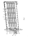
- FIG. 1 time schematically an electric heater with a two-part plastic frame 2, the frame shells are clipped together and a heating block comprising a plurality of designated with reference numeral 4 PTC heating elements and not shown in the illustration radiator elements in it.
- the frame has a frame opening 6, which is penetrated by longitudinal struts 8 and cross struts 10.
- the cross struts 10 serve to reinforce the frame 2 and the abutment of a force, which by one example, at least on one side at the longitudinal edge of the frame 2 in this recorded Spring is effected. This spring braces the layers of the layered heating block within the frame 2 against each other.
- the longitudinal struts 8 are located at the level of the individual PTC heating rods 4. It is to be envisaged that between adjacent longitudinal struts 8, one of the slat layers is provided in the form of a meandering bent sheet-metal strip, for example an aluminum sheet.
- the PTC heating elements 4 consisting of parallel extending metal bands that record between them not shown PTC elements in it. These PTC elements are usually accommodated in a so-called positioning frame which, with a smaller thickness than the PTC elements, holds them between the two metal strips.
- one of the metal strips is laterally extended beyond the layered structure. It is assumed that these are the ends of the reproduced in the drawing metal strips 12, which form terminal lugs 14 outside of the layered structure.
- the terminal lugs 14 are provided with a smaller width than the metal strips 12 in the region of the layered structure. All terminal lugs 14 extend parallel to each other and are provided substantially at a constant distance relative to each other.
- the terminal lugs 14 are exposed outside the frame 12 and are all electrically contacted with connection elements 16, 18. Specifically, the terminal lugs 14.1, 14.3 and 14.5 are connected to the formed as a plus terminal member 16, whereas the terminal lugs 14.2 and 14.4 are electrically connected to the ground terminal member 18.
- the respective connection elements 16, 18 form terminal tongues 20, 22 to a contact plug for the power current, which are aligned with an extension parallel to the metal strips 12.
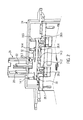
- connection elements 16, 18 are located in a connector housing 24 which is projected eccentrically by a plug housing part 26, which receives the connection tongues 20, 22 in itself and functional surfaces for locking a mating connector, not shown, the female plug contact for receiving the connection tabs 20, 22nd includes, trains.
- the positive connection element 16 comprises three tabs 28 formed by punching machining, which are laterally adjacent to a connecting web in the extension direction of the connection lugs 14 30 are provided and formed in one piece with this.
- Said connecting web 30 of the positive connection element 16 has at the end two lugs 28.1 and 28.5, which are provided offset relative to the connecting web 30 in the direction of the layered structure, and a tab 28.3, offset on the opposite side to the connecting web 30 at this is formed.
- the tabs are formed by free cutting and bending, ie by punch-bending machining of a piece of sheet metal, which forms the connecting web 30 and the associated terminal tongue 20.
- the terminal tongue 20 is provided by bending relative to the plane of extension of the connecting web 30 parallel to the extension direction of the terminal lugs 14.
- the ground connection element 18 has only two tabs 28.2 and 28.4, which project beyond a connecting web 32 of the ground connection element 18 in the direction of the layered structure.
- All lugs 28 are formed for resilient receiving associated terminal lugs 14.
- Each of the tabs 28 has - as in FIG. 3 illustrates - a parallel to a main side surface of the associated terminal lug 14 extending tab base 34 and two of the tab base 34 on opposite sides outgoing tab arms 36, the free ends extending substantially parallel to the tab base 34.
- the strap arms 36 are bent around in such a way that they elastically receive the associated connection lug 14 and make electrical contact with the associated connection element 16 or 18.
- the corresponding tabs 28 and the connecting webs 30, 32 and the associated connection tabs 20 and 22 are formed from a metal strip by punching and bending.
- tabs 28.1, 28.3 and 28.5 are provided on the same side laterally to the connecting web 30.
- the sheet material of the ground connection element 18 is bent, so that its tab 28.2 is between the tabs 28.1 and 28.3 for the positive pole and the tab 28.4 is between the tabs 28.3 and 28.5 for the positive pole.
- the arrangement shown is only insignificantly wider than the width of the connection tabs 20, 22 or of the respective tabs 28.
- the width is to be understood as the extension which extends at right angles to the longitudinal extent of the respective connection webs 30 and 32.
- first Laschenarm 36.1 by a cutout against the connecting web and a second Laschenarm 36.2 by free cutting against the tab base 34, which forms a mounting portion 38 is formed in each case.
- the two outer tabs 28.1 and 28.5 respectively form support points for the attachment of the corresponding connection element 16, 18 to the sheet metal strips 12. These bases are effective when sliding the plug housing 24 on the frame 2 in the manner described below.
- the connector housing 24 is attached by clipping on the plastic frame 2 with this.
- the terminal lugs 14 are inserted into the associated tabs 28.
- Individual tabs 28 may be arranged so with respect to the associated metal strips 12, that at the transition between the slightly wider sheet metal strips 12 and the terminal lugs 14 formed by these metal strips 12, an abutment of the tabs 28 is effected.
- the connection elements 16, 18 are preferably connected by encapsulation with the plastic material of the plug housing 24.
Landscapes
- Engineering & Computer Science (AREA)
- Physics & Mathematics (AREA)
- Thermal Sciences (AREA)
- Mechanical Engineering (AREA)
- Chemical & Material Sciences (AREA)
- Combustion & Propulsion (AREA)
- General Engineering & Computer Science (AREA)
- Air-Conditioning For Vehicles (AREA)
- Resistance Heating (AREA)
Abstract
Description
- Die vorliegende Erfindung betrifft eine elektrische Heizvorrichtung für ein Kraftfahrzeug mit einem Rahmen, in dem ein geschichteter umfassend mehrere parallele Blechbänder und dazwischen angeordnete PTC-Elemente aufweisende PTC-Heizstäbe und mehrere Radiatorelemente vorgesehen sind, wobei ausgewählte Blechbänder der PTC-Heizstäbe zur Bildung von elektrischen Anschlussfahnen seitlich über den geschichteten Aufbau hinaus verlängert sind, und mit einem mit dem Rahmen verbundenen Steckergehäuse.
- Eine derartige gattungsgemäße elektrische Heizvorrichtung ist beispielsweise aus der auf die Anmelderin zurückgehenden
EP 1 157 867 B1 bzw. derEP 1 432 287 A1 bekannt. Bei dem letztgenannten Stand der Technik ist das Steckergehäuse mit dem Rahmen verrastet und weist Durchlässe für die ausgewählten Blechbänder auf. Teilweise sind die Blechbänder relativ zu den Ebenen der PTC-Heizstäbe innerhalb des geschichteten Aufbaus durch Umbiegen versetzt vorgesehen. - Bei dem vorerwähnten gattungsbildenden Stand der Technik sind mehrere Blechbänder zur Ausbildung von Anschlussfahnen innerhalb des Steckergehäuses zum elektrischen Anschluss an einen Gegenstecker vorgesehen (
EP 1 432 287 A1 ). Bei dem anderen zuvor genannten Stand der Technik (EP 1 157 867 B1 ) ist innerhalb des Steckergehäuses eine Steuervorrichtung vorgesehen, welche eine Platine aufweist, mit welcher ausgewählte Blechbänder respektive deren Anschlussfahnen elektrisch verbunden sind. Das Steckergehäuse dient in dem letztgenannten Fall zum Anstecken des Anschlusses an den geschichteten Aufbau. Es weist aber auch Anschlüsse für den Leistungsstrom auf, die als Steckeranschlüsse ausgebildet sein können. Des Weiteren hat das Steckergehäuse üblicherweise elektrische Steckkontakte für die Steuerleitung, die zu der Leiterplatte innerhalb des Steckergehäuses führt. - Der vorliegenden Erfindung liegt das Problem zugrunde, eine einfach aufgebaute elektrische Heizvorrichtung für ein Kraftfahrzeug anzugeben.
- Zur Lösung dieses Problems wird mit der vorliegenden Erfindung eine elektrische Heizvorrichtung mit den Merkmalen von Anspruch 1 angegeben. Diese unterscheidet sich von dem gattungsbildenden Stand der Technik dadurch, dass in dem Steckergehäuse ein Anschlusselement vorgesehen ist, welches eine Steckerzunge und wenigstens eine Kontaktzungenaufnahme ausbildet. Durch die Kontaktzungenaufnahme kann ein Kontakt zwischen dem Anschlusselement und wenigstens einer zugeordneten Anschlussfahne ausgebildet werden. Das Anschlusselement verbindet dementsprechend als separates Bauteil elektrisch eine an dem Steckergehäuse freiliegende Anschlusszunge zum Anschluss der elektrischen Heizvorrichtung, üblicherweise an den Leistungsstrom mit einer, vorzugsweise mehreren Anschlussfahnen. Das entsprechende Anschlusselement bildet somit eine einfach ausgebildete elektrische Brücke, um die mehreren, vorzugsweise in Verlängerung der PTC-Heizstäbe vorgesehenen Anschlussfahnen mit wenigstens einer Anschlusszunge elektrisch zu verbinden.
- Mit dieser Ausgestaltung kann das Umbiegen von Blechbändern zur gewünschten Anordnung der durch diese ausgebildeten Anschlussfahnen verzichtet werden. Die PTC-Heizstäbe lassen sich daher ohne lagebezogene Individualisierung in den geschichteten Aufbau einbauen. Sämtliche PTC-Heizstäbe können daher identisch ausgebildet sein. Des Weiteren kann beispielsweise auf eine Platine oder dergleichen zum elektrischen Anschluss an den geschichteten Aufbau, der auch als Heizblock bezeichnet wird, verzichtet werden.
- Die Anschlusselemente sind vorzugsweise als Stromschienen ausgebildet, d.h. sind aus einem Blechstreifen mit guter elektrischer Leitfähigkeit ausgeformt. Vorzugsweise ist das wenigstens eine Anschlusselement durch Stanz-Biege-Bearbeitung hergestellt. Besonders bevorzugt sind lediglich zwei Anschlusselemente vorgesehen. Diese bilden im Bereich des Steckergehäuses zwei Anschlusszungen zum Anschluss an Masse einerseits und an den Plus-Pol des Fahrzeuges andererseits aus. Diese beiden Anschlusselemente verbinden vorzugsweise sämtliche aus dem geschichteten Aufbau herausgeführten Anschlussfahnen.
- Die vorliegende Erfindung bietet den Vorteil, eine an sich verfügbare und beispielsweise für den Betrieb in Verbindung mit einer elektronischen Steuerungsvorrichtung mit Leistungstransistoren, die auf einer Leiterplatte vorgesehen sind, wobei die Leiterplatte elektrisch mit den jeweiligen Anschlussfahnen verbunden werden kann, bereits bestehende elektrische Heizvorrichtung als einfachste Ausgestaltung auszuformen, bei welcher sämtliche Anschlussfahnen elektrisch mit den beiden Anschlusszungen verbunden sind. Die ansonsten bei Einbau einer aufwendigen Steuervorrichtung in das Steckergehäuse aufwendig ausgestaltete elektrische Heizvorrichtung kann danach einfach ausgebildet werden, wobei in dem einfachen Fall, bei dem sämtliche Anschlussfahnen über die zwei Anschlusselemente elektrisch verbindbar sind, auf Heizstufen verzichtet wird. Vielmehr kann die elektrische Heizvorrichtung lediglich vollständig ein- bzw. ausgeschaltet werden. Einzelne Heizstränge können bei einer derartigen Ausgestaltung nicht separat angesteuert werden, was bis heute mit Rücksicht auf die nur begrenzt verfügbare Bordnetzspannung als nachteilig angesehen wird.
- Gemäß einer bevorzugten Weiterbildung der vorliegenden Erfindung bildet wenigstens eines der Anschlusselemente wenigstens einer Kontaktzungenaufnahme in Form einer Lasche aus, welche den Steckkontakt ausbildet. Die Lasche ist danach so ausgeformt, dass sie die Anschlussfahne in sich aufnimmt und dabei das Anschlusselement elektrisch mit der zugeordneten Anschlussfahne verbindet. Die Lasche ist vorzugsweise durch Blechbiegen geformt und hat bevorzugt wenigstens einen Abschnitt, der mit einer gewissen elastischen Vorspannung an der Außenfläche der Anschlussfahne anliegt, um diese sicher elektrisch mit dem Anschlusselement zu kontaktieren. Vorzugsweise weist das Anschlusselement wenigstens zwei Laschen auf, um zwei unterschiedliche Anschlussfahnen mit dem Anschlusselement elektrisch zu kontaktieren. Bei dieser bevorzugten Ausgestaltung erstreckt sich das besagte Anschlusselement über mehrere Schichten des Schichtaufbaus und erstreckt sich regelmäßig quer zu selbigen. Üblicherweise erstreckt sich ein solcher Art ausgebildetes Anschlusselement als länglicher Blechstreifen im Wesentlichen rechtwinklig zu der Erstreckung der einzelnen Blechbänder bzw. Anschlussfahnen. Eine solche Ausgestaltung erlaubt eine relativ kompakt bauende elektrische Heizvorrichtung mit einem relativ kompakten Steckergehäuse.
- Im Hinblick auf eine bestmögliche elektrische Kontaktierung mit den Anschlussfahnen weist jede einer entsprechenden Anschlussfahne zugeordnete Lasche gegenläufig und aufeinander zu umbogene Laschenarme auf, deren freie Enden gegenüberliegend einer Laschenbasis vorgesehen sind. Die Basis erstreckt sich dabei vorzugsweise im Wesentlichen parallel zu einer Längsseite der Anschlussfahne. Entsprechendes gilt für die beiden gegenüberliegend der Laschenbasis vorgesehenen Laschenarme. Dabei kann die mit der Anschlussfahne zusammenwirkende Oberfläche der Laschenbasis bzw. die Oberflächen der Laschenarme so ausgestaltet sein, dass eine punktuelle und vorbestimmte Kontaktfläche gegeben ist. So kann eine sich konvex in Richtung auf die Anschlussfahne vorgesehene Wölbung ausgebildet sein, die darüber hinaus zur verbesserten elektrischen Leitung mit einem gut leitenden Material wie beispielsweise Silber oder einer Silber-Zinn-Legierung beschichtet ist. Die Laschenarme sollten so in Richtung auf die Anschlussfahne geformt sein, dass diese eine gewisse elastische Anlage an der der Laschenbasis gegenüberliegenden Längsseite der Anschlussfahne bewirken.
- Gemäß einer weiteren bevorzugten Ausgestaltung der vorliegenden Erfindung, bei der die Laschenbasis in Einsteckrichtung der Anschlussfahnen eine größere Erstreckung als die Laschenarme hat, wird davon ausgegangen, dass die Laschenarme zwar eine gewisse elektrische Kontaktierung mit der Anschlussfahne bewirken, jedoch hauptsächlich die Laschen durch elastische Vorspannung mit der Anschlussfahne kontaktieren und so einen Steckkontakt ausbilden, wohingegen die Laschenbasis durch die gegenüber der Laschenarme vergrößerte Oberfläche vornehmlich die elektrische Übertragung des Leistungsstromes bewirkt.
- Bevorzugte Weiterbildungen der Erfindung sind in den weiteren abhängigen Ansprüchen angegeben.
- Weitere Einzelheiten und Vorteile der vorliegenden Erfindung ergeben sich aus der nachfolgenden Beschreibung eines Ausführungsbeispiels in Verbindung mit der Zeichnung. In dieser zeigen:
- Figur 1
- eine perspektivische Längsschnittansicht mit geschnittenem Steckergehäuse des Ausführungsbeispiels;
- Figur 2
- das Steckergehäuse des Ausführungsbeispieles nach
Figur 1 in vergrößerter Darstellung, und - Figur 3
- die beiden Anschlusselemente des Ausführungsbeispieles in einer im Ausführungsbeispiel verwirklichten Anordnung zueinander.
-
Figur 1 zeit schematisch eine elektrische Heizvorrichtung mit einem zweiteiligen Kunststoffrahmen 2, dessen Rahmenschalen miteinander verclipst sind und der einen Heizblock umfassend mehrere mit Bezugszeichen 4 gekennzeichnete PTC-Heizstäbe und in der Darstellung nicht gezeigte Radiatorelemente in sich aufnimmt. Der Rahmen hat eine Rahmenöffnung 6, die durch Längsstreben 8 und Querstreben 10 durchsetzt ist. Die Querstreben 10 dienen der Verstärkung des Rahmens 2 und der Widerlagerung einer Kraft, die durch eine beispielsweise jedenfalls einseitig am Längsrand des Rahmens 2 in diesem aufgenommenen Feder bewirkt wird. Diese Feder verspannt die Lagen des geschichteten Heizblock innerhalb des Rahmens 2 gegeneinander. - Die Längsstreben 8 befinden sich auf Höhe der einzelnen PTC-Heizstäbe 4. Man muss sich vorstellen, dass zwischen benachbarten Längsstreben 8 jeweils eine der Lamellenlagen vorgesehen ist in Form eines mäandrierend gebogenen Blechstreifens, beispielsweise eines Aluminiumblechs.
- Die PTC-Heizstäbe 4 bestehend aus sich parallel erstreckenden Blechbändern, die zwischen sich vorliegend nicht gezeigte PTC-Elemente in sich aufnehmen. Diese PTC-Elemente sind üblicherweise in einem sogenannten Positionsrahmen aufgenommen, der mit geringere Dicke als die PTC-Elemente diese zwischen den beiden Blechbändern hält.
- Bei dem gezeigten Ausführungsbeispiel ist jeweils eines der Blechbänder seitlich über den geschichteten Aufbau hinaus verlängert. Es sei angenommen, dass es sich hierbei um die Enden der in der Zeichnung wiedergegebenen Blechbänder 12 handelt, die außerhalb des geschichteten Aufbaus Anschlussfahnen 14 ausbilden. Die Anschlussfahnen 14 sind mit geringerer Breite als die Blechbänder 12 im Bereich des geschichteten Aufbaus vorgesehen. Sämtliche Anschlussfahnen 14 erstrecken sich parallel zueinander und sind im Wesentlichen mit konstantem Abstand relativ zueinander vorgesehen. Die Anschlussfahnen 14 liegen außerhalb des Rahmens 12 frei und sind sämtlich mit Anschlusselementen 16, 18 elektrisch kontaktiert. Konkret sind die Anschlussfahnen 14.1, 14.3 und 14.5 mit dem als Plus-Anschlusselement ausgebildeten Bauteil 16 verbunden, wohingegen die Anschlussfahnen 14.2 und 14.4 elektrisch mit dem Masse-Anschlusselement 18 verbunden sind. Die jeweiligen Anschlusselemente 16, 18 bilden Anschlusszungen 20, 22 zu einem Kontaktstecker für den Leistungsstrom aus, die mit einer Erstreckung parallel zu den Blechbändern 12 ausgerichtet sind.
- Die Anschlusselemente 16, 18 befinden sich in einem Steckergehäuse 24, das exzentrisch von einem Steckergehäuseteil 26 überragt wird, welches die Anschlusszungen 20, 22 in sich aufnimmt und Funktionsflächen für die Verrastung eines nicht gezeigten Gegensteckers, der weibliche Steckkontakt zur Aufnahme der Anschlusszungen 20, 22 umfasst, ausbildet.
- Das Plus-Anschlusselement 16 umfasst drei durch Stanzbearbeitung ausgeformte Laschen 28, die in Erstreckungsrichtung der Anschlussfahnen 14 seitlich neben einem Anschlusssteg 30 vorgesehen und einteilig mit diesem ausgebildet sind. Der besagte Anschlusssteg 30 des Plus-Anschlusselementes 16 hat endseitig zwei Laschen 28.1 und 28.5, die relativ zu dem Anschlusssteg 30 in Richtung auf den geschichteten Aufbau hin versetzt vorgesehen sind, und eine Lasche 28.3, die auf der gegenüberliegenden Seite versetzt zu dem Anschlusssteg 30 an diesen angeformt ist. Die Laschen sind durch Freischneiden und Umbiegen, d.h. mittels Stanz-Biege-Bearbeitung aus einem Blechstück geformt, welches den Anschlusssteg 30 sowie die zugehörige Anschlusszunge 20 ausformt. Auch die Anschlusszunge 20 ist durch Umbiegen relativ zu der Erstreckungsebene des Anschlusssteges 30 parallel zu der Erstreckungsrichtung der Anschlussfahnen 14 vorgesehen.
- Das Masse-Anschlusselement 18 hat lediglich zwei Laschen 28.2 und 28.4, welche einen Anschlusssteg 32 des Masse-Anschlusselementes 18 in Richtung auf den geschichteten Aufbau überragen.
- Sämtliche Laschen 28 sind zur federnden Aufnahme zugeordneter Anschlussfahnen 14 ausgeformt. Jede einzelne der Laschen 28 hat - wie in
Figur 3 verdeutlicht - einen sich parallel zu einer Hauptseitenfläche der zugeordneten Anschlussfahne 14 erstreckende Laschenbasis 34 sowie zwei von der Laschenbasis 34 an gegenüberliegenden Seiten abgehende Laschenarme 36, deren freie Enden sich im Wesentlichen parallel zu der Laschenbasis 34 erstreckt. Die Laschenarme 36 sind derart umbogen, dass sie die zugeordnete Anschlussfahne 14 elastisch aufnehmen und elektrisch mit dem zugeordneten Anschlusselement 16 bzw. 18 kontaktieren. - Wie aus
Figur 3 ersichtlich, sind die entsprechenden Laschen 28 und die Anschlussstege 30, 32 sowie die zugehörigen Anschlusszungen 20 bzw. 22 aus einem Blechstreifen durch Stanzen und Biegen ausgebildet. - Die an dem Plus-Anschlusselement 16 vorgesehenen Laschen 28.1, 28.3 und 28.5 sind an der gleichen Seite seitlich zu dem Anschlusssteg 30 vorgesehen. In gegenläufiger Richtung ist das Blechmaterial des Masse-Anschlusselementes 18 gebogen, so dass deren Lasche 28.2 sich zwischen den Laschen 28.1 und 28.3 für den Pluspol und deren Lasche 28.4 sich zwischen den Laschen 28.3 und 28.5 für den Pluspol befindet. Die in
Figur 3 gezeigte Anordnung ist nur unwesentlich breiter als die Breite der Anschlusszungen 20, 22 bzw. der jeweiligen Laschen 28. Als Breite ist diejenige Erstreckung zu verstehen, die sich rechtwinklig zu der Längserstreckung der jeweiligen Anschlussstege 30 bzw. 32 erstreckt. - Von den Laschenarmen 36 der Laschen 28 ist jeweils ein erster Laschenarm 36.1 durch einen Freischnitt gegenüber dem Anschlusssteg und ein zweiter Laschenarm 36.2 durch Freischneiden gegenüber der Laschenbasis 34, die einen Befestigungsabschnitt 38 ausbildet, gebildet. An dem Plus-Anschlusselement 16 bilden die beiden äußeren Laschen 28.1 und 28.5 jeweils Stützpunkte für die Befestigung des entsprechenden Anschlusselementes 16, 18 an den Blechbändern 12 aus. Diese Stützpunkte werden beim Aufschieben des Steckergehäuses 24 auf den Rahmen 2 in der nachfolgend beschriebenen Weise wirksam.
- Das Steckergehäuse 24 ist durch Aufclipsen auf der den Kunststoffrahmen 2 mit diesem befestigt. Dabei werden zunächst die Anschlussfahnen 14 in die zugeordneten Laschen 28 eingeschoben. Mit fortschreitender Aufsteckbewegung gleiten die Laschen 28 entlang der entsprechenden Anschlussfahnen 14. Die Bewegung findet ihr Ende, wenn das Steckergehäuse 24 mit den dem stirnseitigen Rand des Rahmens 2 verrastet. Einzelne Laschen 28 können dabei so in Bezug auf die zugeordneten Blechbänder 12 angeordnet sein, dass am Übergang zwischen den etwas breiteren Blechbändern 12 und den durch diese Blechbänder 12 gebildeten Anschlussfahnen 14 eine Anlage der Laschen 28 bewirkt wird. Die Anschlusselemente 16, 18 sind vorzugsweise durch Umspritzen mit dem Kunststoffmaterial des Steckergehäuses 24 verbunden.
-
- 2
- Rahmen
- 4
- PTC-Heizstäbe
- 6
- Rahmenöffnung
- 8
- Längsstreben
- 10
- Querstreben
- 12
- Blechbänder
- 14
- Anschlussfahnen
- 16
- Anschlusselement (Plus-Pol)
- 18
- Anschlusselement (Masse-Pol)
- 20
- Anschlusszunge (Plus-Pol)
- 22
- Anschlusszunge (Masse-Pol)
- 24
- Steckergehäuse
- 26
- Steckergehäuseteil
- 28
- Lasche
- 30
- Anschlusssteg (Plus-Pol)
- 32
- Anschlusssteg (Masse-Pol)
- 34
- Laschenbasis
- 36
- Laschenarm
- 36.1
- erster Laschenarm
- 36.2
- zweiter Laschenarm
- 38
- Laschenbefestigungsabschnitt
Claims (15)
- Elektrische Heizvorrichtung für ein Kraftfahrzeug mit einem Rahmen (2) in dem ein geschichteter Aufbau umfassend mehrere parallele Blechbänder (12) und dazwischen angeordnete PTC-Elemente aufweisende PTC-Heizstäbe (4) und mehrere Radiatorelemente vorgesehen ist, wobei ausgewählte Blechbänder (12) der PTC-Heizstäbe (4) zur Bildung von elektrischen Anschlussfahnen (14) seitlich über den geschichteten Aufbau hinaus verlängert sind, und mit einem mit dem Rahmen (2) verbundenen Steckergehäuse (24),
gekennzeichnet durch
wenigstens ein eine Steckerzunge (20; 22) ausbildendes Anschlusselement (16; 18), das in dem Steckergehäuse (24) aufgenommen ist und wenigstens eine Kontaktzungenaufnahme (28) ausbildet, durch welche ein Steckkontakt zwischen dem Anschlusselement (16, 18) und einer zugeordneten Anschlussfahne (14) gebildet ist. - Elektrische Heizvorrichtung nach einem der vorherigen Ansprüche gekennzeichnet durch eine Masse-Anschlusselement (18) und ein Plus-Anschlusselement (16), wobei das Masse-Anschlusselement (18) in dem Steckergehäuse (24) eine Masse-Anschlusszunge (22) und das Plus-Anschlusselement (16) in dem Steckergehäuse (24) eine Plus-Anschlusszunge (20) ausbildet.
- Elektrische Heizvorrichtung nach einem der vorherigen Ansprüche, dadurch gekennzeichnet, dass das wenigstens eine Anschlusselement (16; 18) zur Ausbildung einer Kontaktzungenaufnahme (28) wenigstens eine durch Blechbiegen geformte Lasche (28) aufweist.
- Elektrische Heizvorrichtung nach Anspruch 3, dadurch gekennzeichnet, dass wenigstens eines der Anschlusselemente (16; 18) einen mehrere Schichten des Schichtaufbaus überbrückenden Anschlusssteg (30; 32) aufweist, an dem wenigstens zwei Laschen (28.2, 28.4; 28.1, 28.3, 28.5) ausgeformt sind.
- Elektrische Heizvorrichtung nach Anspruch 3 oder 4, dadurch gekennzeichnet, dass die Laschen (28) gegenläufig und aufeinander zu umbogene Laschenarme (36) sowie eine gegenüberliegend der freien Enden der Laschenarme (36) vorgesehene Laschenbasis (34) umfassen.
- Elektrische Heizvorrichtung nach Anspruch 5, dadurch gekennzeichnet, dass die Laschenbasis (34) in Einsteckrichtung der Anschlussfahnen (14) eine größere Erstreckung hat als die Laschenarme (36).
- Elektrische Heizvorrichtung nach Anspruch 5 oder 6, dadurch gekennzeichnet, dass die Laschenbasis (34) in etwa rechtwinklig zu dem Anschlusssteg (30; 32) ausgebildet ist.
- Elektrische Heizvorrichtung nach einem der Ansprüche 5 bis 7, dadurch gekennzeichnet, dass die Laschenbasis (34) über einen sich parallel zu dem Anschlusssteg (30; 32) erstreckenden Laschenbefestigungsabschnitt (38) mit dem Anschlusssteg (30; 32) verbunden ist.
- Elektrische Heizvorrichtung nach Anspruch 8, dadurch gekennzeichnet, dass die Laschenbasis (34) durch Freischneiden gegenüber dem Anschlusssteg (30; 32) und einer der Laschenarme (36.1) durch Freischneiden gegenüber der Laschenbasis (34) und der andere Laschenarm (36.2) durch Freischneiden gegenüber dem Anschlusssteg (30, 32) gebildet sind.
- Elektrische Heizvorrichtung nach einem der vorherigen Ansprüche, dadurch gekennzeichnet, dass sich die Steckerzunge (20; 22) rechtwinklig zu dem Anschlusssteg (30; 32) des zugeordneten Anschlusselementes (16; 18) erstreckt.
- Elektrische Heizvorrichtung nach einem der vorherigen Ansprüche, dadurch gekennzeichnet, dass die Anschlussfahnen (14) mit geringerer Breite als die Blechbänder (12) ausgebildet sind und dass die einer Anschlussfahne (14) zugeordnete Lasche (28) auf einem Übergang zwischen der Anschlussfahne (14) und dem zugeordneten Blechband (12) aufsitzt.
- Elektrische Heizvorrichtung nach Anspruch 11, dadurch gekennzeichnet, dass wenigstens zwei Laschen (28.1, 28.3) jeweils eines Anschlusselementes (16; 18) auf dem Übergang zwischen dem Blechband (12) und der Anschlussfahne (14) aufsitzen.
- Elektrische Heizvorrichtung nach einem der vorherigen Ansprüche, dadurch gekennzeichnet, dass sämtliche Anschlussfahnen (14) elektrisch über die Anschlusselemente (16; 18) angeschlossen sind.
- Elektrische Heizvorrichtung nach einem der vorherigen Ansprüche, dadurch gekennzeichnet, dass die Anschlussfahnen (14) in dem Steckergehäuse (24) befestigt sind und dass das Steckergehäuse (24) auf den Rahmen (2) aufgesteckt ist.
- Elektrische Heizvorrichtung nach einem der vorherigen Ansprüche, dadurch gekennzeichnet, dass der Rahmen (2) und das Steckergehäuse (24) aus Kunststoff gebildet sind.
Applications Claiming Priority (1)
| Application Number | Priority Date | Filing Date | Title |
|---|---|---|---|
| DE202009005582U DE202009005582U1 (de) | 2009-04-14 | 2009-04-14 | Elektrische Heizvorrichtung |
Publications (3)
| Publication Number | Publication Date |
|---|---|
| EP2242327A1 true EP2242327A1 (de) | 2010-10-20 |
| EP2242327B1 EP2242327B1 (de) | 2016-05-25 |
| EP2242327B2 EP2242327B2 (de) | 2020-03-25 |
Family
ID=42307881
Family Applications (1)
| Application Number | Title | Priority Date | Filing Date |
|---|---|---|---|
| EP10002636.8A Active EP2242327B2 (de) | 2009-04-14 | 2010-03-12 | Elektrische Heizvorrichtung |
Country Status (2)
| Country | Link |
|---|---|
| EP (1) | EP2242327B2 (de) |
| DE (1) | DE202009005582U1 (de) |
Cited By (6)
| Publication number | Priority date | Publication date | Assignee | Title |
|---|---|---|---|---|
| EP2515388A1 (de) | 2011-04-18 | 2012-10-24 | Eberspächer catem GmbH & Co. KG | Elektrische Heizvorrichtung |
| EP2806707A1 (de) * | 2013-05-21 | 2014-11-26 | Behr France Rouffach SAS | Heizkörper |
| EP3480532A1 (de) * | 2017-11-02 | 2019-05-08 | Eberspächer catem GmbH & Co. KG | Elektrische heizvorrichtung |
| DE102018220858A1 (de) | 2018-12-03 | 2020-06-04 | Eberspächer Catem Gmbh & Co. Kg | Elektrische Heizvorrichtung |
| CN111629515A (zh) * | 2019-02-28 | 2020-09-04 | 法雷奥汽车空调湖北有限公司 | 汇流条系统 |
| DE102019132998A1 (de) * | 2019-12-04 | 2021-06-10 | Eichenauer Heizelemente Gmbh & Co. Kg | Behälterheizung |
Families Citing this family (3)
| Publication number | Priority date | Publication date | Assignee | Title |
|---|---|---|---|---|
| FR3075553B1 (fr) * | 2017-12-19 | 2022-05-20 | Valeo Systemes Thermiques | Dispositif de chauffage electrique avec moyens de mise a la masse |
| FR3083744A1 (fr) * | 2018-07-13 | 2020-01-17 | Valeo Systemes Thermiques | Cadre de dispositif de chauffage electrique de vehicule |
| CN111619303A (zh) * | 2019-02-28 | 2020-09-04 | 法雷奥汽车空调湖北有限公司 | 具有壳体组件的加热装置 |
Citations (7)
| Publication number | Priority date | Publication date | Assignee | Title |
|---|---|---|---|---|
| WO2002057100A2 (de) * | 2001-01-17 | 2002-07-25 | Beru Aktiengesellschaft | Elektrische heizung für ein kraftfahrzeug |
| EP1157867B1 (de) | 2000-05-23 | 2002-12-18 | Catem GmbH & Co.KG | Elektrische Heizvorrichtung, insbesondere für den Einsatz in Kraftfahrzeugen |
| EP1432287A1 (de) | 2002-12-19 | 2004-06-23 | Catem GmbH & Co.KG | Elektrische Heizvorrichtung mit Gehäuse |
| EP1521499A1 (de) * | 2003-10-02 | 2005-04-06 | Behr France S.A.R.L. | Steckanordnung für eine Heizungsanordnung mit PTC-Elementen, insbesondere für ein Kraftfahrzeug |
| EP1580495A1 (de) * | 2004-03-22 | 2005-09-28 | Halla Climate Control Corporation | Elektrische Heizvorrichtung |
| DE202007001079U1 (de) * | 2007-01-18 | 2008-05-21 | Eichenauer Heizelemente Gmbh & Co. Kg | Kraftfahrzeugheizung |
| EP1928214A1 (de) * | 2006-11-30 | 2008-06-04 | Catem GmbH & Co.KG | Elektrische Heizvorrichtung |
Family Cites Families (9)
| Publication number | Priority date | Publication date | Assignee | Title |
|---|---|---|---|---|
| DE3869773C5 (de) † | 1988-07-15 | 2010-06-24 | Dbk David + Baader Gmbh | Radiator. |
| JP3298493B2 (ja) † | 1997-03-18 | 2002-07-02 | 株式会社デンソー | 車両暖房用熱交換器 |
| DE59911409D1 (de) † | 1999-06-15 | 2005-02-10 | David & Baader Dbk Spezfab | Heizvorrichtung zur Lufterwärmung |
| IT249474Y1 (it) † | 2000-02-17 | 2003-05-19 | Eltek Spa | Radiatore elettrico. |
| EP1503153B1 (de) † | 2003-07-31 | 2011-03-30 | Behr France Rouffach SAS | Vorrichtung zum Austausch von Wärme |
| DE50308124D1 (de) † | 2003-07-31 | 2007-10-18 | Behr France Rouffach Sas | Elektrische Heizvorrichtung |
| DE602004002556T2 (de) † | 2004-03-09 | 2007-01-18 | Cebi S.P.A., Cascine Vica Rivoli | Elektrische Heizvorrichtung für Kraftfahrzeugventilationseinrichtung |
| ATE399664T1 (de) † | 2004-07-28 | 2008-07-15 | Behr France Rouffach Sas | Heizungsanordnung mit einem heizelement, insbesondere für ein kraftfahrzeug |
| DE202005002115U1 (de) † | 2005-02-09 | 2006-06-14 | Catem Gmbh & Co. Kg | Elektrische Heizvorrichtung, insbesondere für den Einsatz in Kraftfahrzeugen |
-
2009
- 2009-04-14 DE DE202009005582U patent/DE202009005582U1/de not_active Expired - Lifetime
-
2010
- 2010-03-12 EP EP10002636.8A patent/EP2242327B2/de active Active
Patent Citations (7)
| Publication number | Priority date | Publication date | Assignee | Title |
|---|---|---|---|---|
| EP1157867B1 (de) | 2000-05-23 | 2002-12-18 | Catem GmbH & Co.KG | Elektrische Heizvorrichtung, insbesondere für den Einsatz in Kraftfahrzeugen |
| WO2002057100A2 (de) * | 2001-01-17 | 2002-07-25 | Beru Aktiengesellschaft | Elektrische heizung für ein kraftfahrzeug |
| EP1432287A1 (de) | 2002-12-19 | 2004-06-23 | Catem GmbH & Co.KG | Elektrische Heizvorrichtung mit Gehäuse |
| EP1521499A1 (de) * | 2003-10-02 | 2005-04-06 | Behr France S.A.R.L. | Steckanordnung für eine Heizungsanordnung mit PTC-Elementen, insbesondere für ein Kraftfahrzeug |
| EP1580495A1 (de) * | 2004-03-22 | 2005-09-28 | Halla Climate Control Corporation | Elektrische Heizvorrichtung |
| EP1928214A1 (de) * | 2006-11-30 | 2008-06-04 | Catem GmbH & Co.KG | Elektrische Heizvorrichtung |
| DE202007001079U1 (de) * | 2007-01-18 | 2008-05-21 | Eichenauer Heizelemente Gmbh & Co. Kg | Kraftfahrzeugheizung |
Cited By (10)
| Publication number | Priority date | Publication date | Assignee | Title |
|---|---|---|---|---|
| EP2515388A1 (de) | 2011-04-18 | 2012-10-24 | Eberspächer catem GmbH & Co. KG | Elektrische Heizvorrichtung |
| EP2806707A1 (de) * | 2013-05-21 | 2014-11-26 | Behr France Rouffach SAS | Heizkörper |
| EP2806708A1 (de) * | 2013-05-21 | 2014-11-26 | Behr France Rouffach SAS | Heizkörper |
| EP3480532A1 (de) * | 2017-11-02 | 2019-05-08 | Eberspächer catem GmbH & Co. KG | Elektrische heizvorrichtung |
| EP3480532B1 (de) | 2017-11-02 | 2020-08-19 | Eberspächer catem GmbH & Co. KG | Elektrische heizvorrichtung |
| DE102018220858A1 (de) | 2018-12-03 | 2020-06-04 | Eberspächer Catem Gmbh & Co. Kg | Elektrische Heizvorrichtung |
| EP3667197A1 (de) | 2018-12-03 | 2020-06-17 | Eberspächer catem GmbH & Co. KG | Elektrische heizvorrichtung |
| US11912106B2 (en) | 2018-12-03 | 2024-02-27 | Eberspächer Catem Gmbh & Co. Kg | Electric heating device |
| CN111629515A (zh) * | 2019-02-28 | 2020-09-04 | 法雷奥汽车空调湖北有限公司 | 汇流条系统 |
| DE102019132998A1 (de) * | 2019-12-04 | 2021-06-10 | Eichenauer Heizelemente Gmbh & Co. Kg | Behälterheizung |
Also Published As
| Publication number | Publication date |
|---|---|
| DE202009005582U1 (de) | 2010-09-02 |
| EP2242327B2 (de) | 2020-03-25 |
| EP2242327B1 (de) | 2016-05-25 |
Similar Documents
| Publication | Publication Date | Title |
|---|---|---|
| EP2242327B1 (de) | Elektrische Heizvorrichtung | |
| EP1207588B1 (de) | Elektrischer Verbinder für flexible Flachkabel oder flexible Leiterplatten | |
| DE102015114741B4 (de) | Steckverbinder und Set aus Steckverbinder und Verbinderteil | |
| EP3293833B1 (de) | Stromschienenverbinder | |
| EP3375048B1 (de) | Steckkontakt | |
| EP0959529B1 (de) | Elektrische Anschlussbaueinheit | |
| DE102013013458B3 (de) | Kontaktelement | |
| EP2475057B1 (de) | Kabeltragvorrichtung | |
| DE102013107156B4 (de) | Leiterplattenverbinder | |
| DE19949387B4 (de) | Kontaktteil für Anschlussklemme | |
| DE102009019699A1 (de) | Anschlussklemme für Leiterplatten | |
| DE102008055721B4 (de) | Reihenklemme mit Stromschiene, Stromschiene für eine Reihenklemme und Verfahren zur Herstellung einer derartigen Stromschiene | |
| EP1357642B1 (de) | Anschlusssystem | |
| DE1765978B1 (de) | Schaltungsblock zum elektrischen verbinden mittels steck verbindungen von elektrischen schaltungselementen | |
| DE10255674B4 (de) | Reihenklemme mit steckbarem Querbrücker | |
| EP3353860B1 (de) | Anschlussgehäuse mit einer anschlussvorrichtung für leiter | |
| DE102017117300A1 (de) | Querbrücker und Reihenklemmenanordnung | |
| DE102016107898B4 (de) | Laterale Leiterplattenverbindung | |
| DE102015113512B3 (de) | Klemmanordnung und Federkraftklemme | |
| DE19964616B4 (de) | Klemme zum elektrischen Verbinden wenigstens eines elektrischen Kontaktelements mit einem Leiterdraht und Verfahren zum Montieren einer Klemme | |
| DE102017108444B4 (de) | Elektrisches Kontaktelement für eine Leiterplatte und damit ausgestattete Stromschnittstelle | |
| DE3434969C2 (de) | Schraubenlose Anschlußklemme | |
| DE102015100912A1 (de) | Leiterplatten-Verbinderanordnung und Leiterplattenverbinder hierzu | |
| DE102011120864B4 (de) | Mehrpoliges Reitersicherungselement | |
| DE4136031C1 (en) | Double plug contact for car electric installation - consists of 2 terminal contact fins integral with strip conductor web |
Legal Events
| Date | Code | Title | Description |
|---|---|---|---|
| PUAI | Public reference made under article 153(3) epc to a published international application that has entered the european phase |
Free format text: ORIGINAL CODE: 0009012 |
|
| AK | Designated contracting states |
Kind code of ref document: A1 Designated state(s): AT BE BG CH CY CZ DE DK EE ES FI FR GB GR HR HU IE IS IT LI LT LU LV MC MK MT NL NO PL PT RO SE SI SK SM TR |
|
| AX | Request for extension of the european patent |
Extension state: AL BA ME RS |
|
| 17P | Request for examination filed |
Effective date: 20101011 |
|
| GRAP | Despatch of communication of intention to grant a patent |
Free format text: ORIGINAL CODE: EPIDOSNIGR1 |
|
| INTG | Intention to grant announced |
Effective date: 20160205 |
|
| GRAS | Grant fee paid |
Free format text: ORIGINAL CODE: EPIDOSNIGR3 |
|
| GRAA | (expected) grant |
Free format text: ORIGINAL CODE: 0009210 |
|
| AK | Designated contracting states |
Kind code of ref document: B1 Designated state(s): AT BE BG CH CY CZ DE DK EE ES FI FR GB GR HR HU IE IS IT LI LT LU LV MC MK MT NL NO PL PT RO SE SI SK SM TR |
|
| REG | Reference to a national code |
Ref country code: GB Ref legal event code: FG4D Free format text: NOT ENGLISH |
|
| REG | Reference to a national code |
Ref country code: CH Ref legal event code: EP |
|
| REG | Reference to a national code |
Ref country code: IE Ref legal event code: FG4D Free format text: LANGUAGE OF EP DOCUMENT: GERMAN Ref country code: AT Ref legal event code: REF Ref document number: 803245 Country of ref document: AT Kind code of ref document: T Effective date: 20160615 |
|
| REG | Reference to a national code |
Ref country code: DE Ref legal event code: R096 Ref document number: 502010011719 Country of ref document: DE |
|
| REG | Reference to a national code |
Ref country code: LT Ref legal event code: MG4D |
|
| REG | Reference to a national code |
Ref country code: NL Ref legal event code: MP Effective date: 20160525 |
|
| PG25 | Lapsed in a contracting state [announced via postgrant information from national office to epo] |
Ref country code: NL Free format text: LAPSE BECAUSE OF FAILURE TO SUBMIT A TRANSLATION OF THE DESCRIPTION OR TO PAY THE FEE WITHIN THE PRESCRIBED TIME-LIMIT Effective date: 20160525 Ref country code: LT Free format text: LAPSE BECAUSE OF FAILURE TO SUBMIT A TRANSLATION OF THE DESCRIPTION OR TO PAY THE FEE WITHIN THE PRESCRIBED TIME-LIMIT Effective date: 20160525 Ref country code: FI Free format text: LAPSE BECAUSE OF FAILURE TO SUBMIT A TRANSLATION OF THE DESCRIPTION OR TO PAY THE FEE WITHIN THE PRESCRIBED TIME-LIMIT Effective date: 20160525 Ref country code: NO Free format text: LAPSE BECAUSE OF FAILURE TO SUBMIT A TRANSLATION OF THE DESCRIPTION OR TO PAY THE FEE WITHIN THE PRESCRIBED TIME-LIMIT Effective date: 20160825 |
|
| PG25 | Lapsed in a contracting state [announced via postgrant information from national office to epo] |
Ref country code: SE Free format text: LAPSE BECAUSE OF FAILURE TO SUBMIT A TRANSLATION OF THE DESCRIPTION OR TO PAY THE FEE WITHIN THE PRESCRIBED TIME-LIMIT Effective date: 20160525 Ref country code: HR Free format text: LAPSE BECAUSE OF FAILURE TO SUBMIT A TRANSLATION OF THE DESCRIPTION OR TO PAY THE FEE WITHIN THE PRESCRIBED TIME-LIMIT Effective date: 20160525 Ref country code: ES Free format text: LAPSE BECAUSE OF FAILURE TO SUBMIT A TRANSLATION OF THE DESCRIPTION OR TO PAY THE FEE WITHIN THE PRESCRIBED TIME-LIMIT Effective date: 20160525 Ref country code: LV Free format text: LAPSE BECAUSE OF FAILURE TO SUBMIT A TRANSLATION OF THE DESCRIPTION OR TO PAY THE FEE WITHIN THE PRESCRIBED TIME-LIMIT Effective date: 20160525 Ref country code: GR Free format text: LAPSE BECAUSE OF FAILURE TO SUBMIT A TRANSLATION OF THE DESCRIPTION OR TO PAY THE FEE WITHIN THE PRESCRIBED TIME-LIMIT Effective date: 20160826 Ref country code: PT Free format text: LAPSE BECAUSE OF FAILURE TO SUBMIT A TRANSLATION OF THE DESCRIPTION OR TO PAY THE FEE WITHIN THE PRESCRIBED TIME-LIMIT Effective date: 20160926 |
|
| PG25 | Lapsed in a contracting state [announced via postgrant information from national office to epo] |
Ref country code: SK Free format text: LAPSE BECAUSE OF FAILURE TO SUBMIT A TRANSLATION OF THE DESCRIPTION OR TO PAY THE FEE WITHIN THE PRESCRIBED TIME-LIMIT Effective date: 20160525 Ref country code: CZ Free format text: LAPSE BECAUSE OF FAILURE TO SUBMIT A TRANSLATION OF THE DESCRIPTION OR TO PAY THE FEE WITHIN THE PRESCRIBED TIME-LIMIT Effective date: 20160525 Ref country code: EE Free format text: LAPSE BECAUSE OF FAILURE TO SUBMIT A TRANSLATION OF THE DESCRIPTION OR TO PAY THE FEE WITHIN THE PRESCRIBED TIME-LIMIT Effective date: 20160525 Ref country code: DK Free format text: LAPSE BECAUSE OF FAILURE TO SUBMIT A TRANSLATION OF THE DESCRIPTION OR TO PAY THE FEE WITHIN THE PRESCRIBED TIME-LIMIT Effective date: 20160525 Ref country code: RO Free format text: LAPSE BECAUSE OF FAILURE TO SUBMIT A TRANSLATION OF THE DESCRIPTION OR TO PAY THE FEE WITHIN THE PRESCRIBED TIME-LIMIT Effective date: 20160525 |
|
| REG | Reference to a national code |
Ref country code: DE Ref legal event code: R026 Ref document number: 502010011719 Country of ref document: DE |
|
| PLBI | Opposition filed |
Free format text: ORIGINAL CODE: 0009260 |
|
| PG25 | Lapsed in a contracting state [announced via postgrant information from national office to epo] |
Ref country code: PL Free format text: LAPSE BECAUSE OF FAILURE TO SUBMIT A TRANSLATION OF THE DESCRIPTION OR TO PAY THE FEE WITHIN THE PRESCRIBED TIME-LIMIT Effective date: 20160525 Ref country code: SM Free format text: LAPSE BECAUSE OF FAILURE TO SUBMIT A TRANSLATION OF THE DESCRIPTION OR TO PAY THE FEE WITHIN THE PRESCRIBED TIME-LIMIT Effective date: 20160525 |
|
| PLBI | Opposition filed |
Free format text: ORIGINAL CODE: 0009260 |
|
| REG | Reference to a national code |
Ref country code: FR Ref legal event code: PLFP Year of fee payment: 8 |
|
| 26 | Opposition filed |
Opponent name: DBK DAVID + BAADER GMBH Effective date: 20170223 |
|
| PLAX | Notice of opposition and request to file observation + time limit sent |
Free format text: ORIGINAL CODE: EPIDOSNOBS2 |
|
| 26 | Opposition filed |
Opponent name: VALEO SYSTEMES THERMIQUES S.A.S Effective date: 20170224 |
|
| PG25 | Lapsed in a contracting state [announced via postgrant information from national office to epo] |
Ref country code: SI Free format text: LAPSE BECAUSE OF FAILURE TO SUBMIT A TRANSLATION OF THE DESCRIPTION OR TO PAY THE FEE WITHIN THE PRESCRIBED TIME-LIMIT Effective date: 20160525 |
|
| PLBB | Reply of patent proprietor to notice(s) of opposition received |
Free format text: ORIGINAL CODE: EPIDOSNOBS3 |
|
| REG | Reference to a national code |
Ref country code: CH Ref legal event code: PL |
|
| GBPC | Gb: european patent ceased through non-payment of renewal fee |
Effective date: 20170312 |
|
| PG25 | Lapsed in a contracting state [announced via postgrant information from national office to epo] |
Ref country code: MC Free format text: LAPSE BECAUSE OF FAILURE TO SUBMIT A TRANSLATION OF THE DESCRIPTION OR TO PAY THE FEE WITHIN THE PRESCRIBED TIME-LIMIT Effective date: 20160525 |
|
| REG | Reference to a national code |
Ref country code: IE Ref legal event code: MM4A |
|
| PG25 | Lapsed in a contracting state [announced via postgrant information from national office to epo] |
Ref country code: LU Free format text: LAPSE BECAUSE OF NON-PAYMENT OF DUE FEES Effective date: 20170312 |
|
| PG25 | Lapsed in a contracting state [announced via postgrant information from national office to epo] |
Ref country code: IE Free format text: LAPSE BECAUSE OF NON-PAYMENT OF DUE FEES Effective date: 20170312 Ref country code: GB Free format text: LAPSE BECAUSE OF NON-PAYMENT OF DUE FEES Effective date: 20170312 Ref country code: LI Free format text: LAPSE BECAUSE OF NON-PAYMENT OF DUE FEES Effective date: 20170331 Ref country code: CH Free format text: LAPSE BECAUSE OF NON-PAYMENT OF DUE FEES Effective date: 20170331 |
|
| REG | Reference to a national code |
Ref country code: BE Ref legal event code: MM Effective date: 20170331 |
|
| REG | Reference to a national code |
Ref country code: FR Ref legal event code: PLFP Year of fee payment: 9 |
|
| REG | Reference to a national code |
Ref country code: AT Ref legal event code: MM01 Ref document number: 803245 Country of ref document: AT Kind code of ref document: T Effective date: 20170312 |
|
| PG25 | Lapsed in a contracting state [announced via postgrant information from national office to epo] |
Ref country code: BE Free format text: LAPSE BECAUSE OF NON-PAYMENT OF DUE FEES Effective date: 20170331 |
|
| PG25 | Lapsed in a contracting state [announced via postgrant information from national office to epo] |
Ref country code: AT Free format text: LAPSE BECAUSE OF NON-PAYMENT OF DUE FEES Effective date: 20170312 |
|
| PG25 | Lapsed in a contracting state [announced via postgrant information from national office to epo] |
Ref country code: MT Free format text: LAPSE BECAUSE OF FAILURE TO SUBMIT A TRANSLATION OF THE DESCRIPTION OR TO PAY THE FEE WITHIN THE PRESCRIBED TIME-LIMIT Effective date: 20160525 |
|
| PG25 | Lapsed in a contracting state [announced via postgrant information from national office to epo] |
Ref country code: HU Free format text: LAPSE BECAUSE OF FAILURE TO SUBMIT A TRANSLATION OF THE DESCRIPTION OR TO PAY THE FEE WITHIN THE PRESCRIBED TIME-LIMIT; INVALID AB INITIO Effective date: 20100312 |
|
| APBM | Appeal reference recorded |
Free format text: ORIGINAL CODE: EPIDOSNREFNO |
|
| APBP | Date of receipt of notice of appeal recorded |
Free format text: ORIGINAL CODE: EPIDOSNNOA2O |
|
| APAH | Appeal reference modified |
Free format text: ORIGINAL CODE: EPIDOSCREFNO |
|
| PG25 | Lapsed in a contracting state [announced via postgrant information from national office to epo] |
Ref country code: BG Free format text: LAPSE BECAUSE OF FAILURE TO SUBMIT A TRANSLATION OF THE DESCRIPTION OR TO PAY THE FEE WITHIN THE PRESCRIBED TIME-LIMIT Effective date: 20160525 |
|
| APAH | Appeal reference modified |
Free format text: ORIGINAL CODE: EPIDOSCREFNO |
|
| PG25 | Lapsed in a contracting state [announced via postgrant information from national office to epo] |
Ref country code: CY Free format text: LAPSE BECAUSE OF NON-PAYMENT OF DUE FEES Effective date: 20160525 |
|
| APBU | Appeal procedure closed |
Free format text: ORIGINAL CODE: EPIDOSNNOA9O |
|
| PG25 | Lapsed in a contracting state [announced via postgrant information from national office to epo] |
Ref country code: MK Free format text: LAPSE BECAUSE OF FAILURE TO SUBMIT A TRANSLATION OF THE DESCRIPTION OR TO PAY THE FEE WITHIN THE PRESCRIBED TIME-LIMIT Effective date: 20160525 |
|
| PUAH | Patent maintained in amended form |
Free format text: ORIGINAL CODE: 0009272 |
|
| STAA | Information on the status of an ep patent application or granted ep patent |
Free format text: STATUS: PATENT MAINTAINED AS AMENDED |
|
| 27A | Patent maintained in amended form |
Effective date: 20200325 |
|
| AK | Designated contracting states |
Kind code of ref document: B2 Designated state(s): AT BE BG CH CY CZ DE DK EE ES FI FR GB GR HR HU IE IS IT LI LT LU LV MC MK MT NL NO PL PT RO SE SI SK SM TR |
|
| REG | Reference to a national code |
Ref country code: DE Ref legal event code: R102 Ref document number: 502010011719 Country of ref document: DE |
|
| PG25 | Lapsed in a contracting state [announced via postgrant information from national office to epo] |
Ref country code: TR Free format text: LAPSE BECAUSE OF FAILURE TO SUBMIT A TRANSLATION OF THE DESCRIPTION OR TO PAY THE FEE WITHIN THE PRESCRIBED TIME-LIMIT Effective date: 20160525 |
|
| PG25 | Lapsed in a contracting state [announced via postgrant information from national office to epo] |
Ref country code: IS Free format text: LAPSE BECAUSE OF FAILURE TO SUBMIT A TRANSLATION OF THE DESCRIPTION OR TO PAY THE FEE WITHIN THE PRESCRIBED TIME-LIMIT Effective date: 20160925 |
|
| REG | Reference to a national code |
Ref country code: FR Ref legal event code: PLFP Year of fee payment: 13 |
|
| PGFP | Annual fee paid to national office [announced via postgrant information from national office to epo] |
Ref country code: FR Payment date: 20220323 Year of fee payment: 13 |
|
| PGFP | Annual fee paid to national office [announced via postgrant information from national office to epo] |
Ref country code: IT Payment date: 20220331 Year of fee payment: 13 |
|
| PG25 | Lapsed in a contracting state [announced via postgrant information from national office to epo] |
Ref country code: FR Free format text: LAPSE BECAUSE OF NON-PAYMENT OF DUE FEES Effective date: 20230331 |
|
| PG25 | Lapsed in a contracting state [announced via postgrant information from national office to epo] |
Ref country code: IT Free format text: LAPSE BECAUSE OF NON-PAYMENT OF DUE FEES Effective date: 20230312 |
|
| PGFP | Annual fee paid to national office [announced via postgrant information from national office to epo] |
Ref country code: DE Payment date: 20240321 Year of fee payment: 15 |