EP2241941A2 - Bilderzeugungsvorrichtung - Google Patents
Bilderzeugungsvorrichtung Download PDFInfo
- Publication number
- EP2241941A2 EP2241941A2 EP10156676A EP10156676A EP2241941A2 EP 2241941 A2 EP2241941 A2 EP 2241941A2 EP 10156676 A EP10156676 A EP 10156676A EP 10156676 A EP10156676 A EP 10156676A EP 2241941 A2 EP2241941 A2 EP 2241941A2
- Authority
- EP
- European Patent Office
- Prior art keywords
- image
- toner
- image forming
- low
- gloss
- Prior art date
- Legal status (The legal status is an assumption and is not a legal conclusion. Google has not performed a legal analysis and makes no representation as to the accuracy of the status listed.)
- Withdrawn
Links
- 238000011144 upstream manufacturing Methods 0.000 claims description 12
- 230000015572 biosynthetic process Effects 0.000 claims description 11
- 238000012546 transfer Methods 0.000 description 49
- 238000012545 processing Methods 0.000 description 22
- 239000003086 colorant Substances 0.000 description 13
- 238000004140 cleaning Methods 0.000 description 11
- 238000010586 diagram Methods 0.000 description 5
- 238000000034 method Methods 0.000 description 5
- 230000000215 hyperchromic effect Effects 0.000 description 3
- 239000000463 material Substances 0.000 description 3
- 239000000853 adhesive Substances 0.000 description 2
- 230000001070 adhesive effect Effects 0.000 description 2
- 238000012937 correction Methods 0.000 description 2
- 238000001514 detection method Methods 0.000 description 2
- 239000011521 glass Substances 0.000 description 2
- 238000003384 imaging method Methods 0.000 description 2
- 238000012986 modification Methods 0.000 description 2
- 230000004048 modification Effects 0.000 description 2
- 229920003002 synthetic resin Polymers 0.000 description 2
- 239000000057 synthetic resin Substances 0.000 description 2
- 239000004962 Polyamide-imide Substances 0.000 description 1
- 239000004642 Polyimide Substances 0.000 description 1
- 238000003705 background correction Methods 0.000 description 1
- 238000006243 chemical reaction Methods 0.000 description 1
- 239000000428 dust Substances 0.000 description 1
- 230000008030 elimination Effects 0.000 description 1
- 238000003379 elimination reaction Methods 0.000 description 1
- 230000003287 optical effect Effects 0.000 description 1
- 239000002245 particle Substances 0.000 description 1
- 229920002312 polyamide-imide Polymers 0.000 description 1
- 229920001225 polyester resin Polymers 0.000 description 1
- 239000004645 polyester resin Substances 0.000 description 1
- 229920001721 polyimide Polymers 0.000 description 1
- 238000000926 separation method Methods 0.000 description 1
Images




Classifications
-
- G—PHYSICS
- G03—PHOTOGRAPHY; CINEMATOGRAPHY; ANALOGOUS TECHNIQUES USING WAVES OTHER THAN OPTICAL WAVES; ELECTROGRAPHY; HOLOGRAPHY
- G03G—ELECTROGRAPHY; ELECTROPHOTOGRAPHY; MAGNETOGRAPHY
- G03G15/00—Apparatus for electrographic processes using a charge pattern
- G03G15/65—Apparatus which relate to the handling of copy material
- G03G15/6582—Special processing for irreversibly adding or changing the sheet copy material characteristics or its appearance, e.g. stamping, annotation printing, punching
- G03G15/6585—Special processing for irreversibly adding or changing the sheet copy material characteristics or its appearance, e.g. stamping, annotation printing, punching by using non-standard toners, e.g. transparent toner, gloss adding devices
-
- G—PHYSICS
- G03—PHOTOGRAPHY; CINEMATOGRAPHY; ANALOGOUS TECHNIQUES USING WAVES OTHER THAN OPTICAL WAVES; ELECTROGRAPHY; HOLOGRAPHY
- G03G—ELECTROGRAPHY; ELECTROPHOTOGRAPHY; MAGNETOGRAPHY
- G03G15/00—Apparatus for electrographic processes using a charge pattern
- G03G15/01—Apparatus for electrographic processes using a charge pattern for producing multicoloured copies
- G03G15/0142—Structure of complete machines
- G03G15/0178—Structure of complete machines using more than one reusable electrographic recording member, e.g. one for every monocolour image
- G03G15/0194—Structure of complete machines using more than one reusable electrographic recording member, e.g. one for every monocolour image primary transfer to the final recording medium
-
- G—PHYSICS
- G03—PHOTOGRAPHY; CINEMATOGRAPHY; ANALOGOUS TECHNIQUES USING WAVES OTHER THAN OPTICAL WAVES; ELECTROGRAPHY; HOLOGRAPHY
- G03G—ELECTROGRAPHY; ELECTROPHOTOGRAPHY; MAGNETOGRAPHY
- G03G2215/00—Apparatus for electrophotographic processes
- G03G2215/00362—Apparatus for electrophotographic processes relating to the copy medium handling
- G03G2215/00789—Adding properties or qualities to the copy medium
- G03G2215/00805—Gloss adding or lowering device
- G03G2215/0081—Gloss level being selectable
Definitions
- the present invention relates to an image forming apparatus.
- an apparatus which has not only a plurality of image forming sections that form images of yellow, magenta, cyan, black, etc. by way of example but also an image forming section that forms an image using a transparent toner to improve the transfer properties of a color image onto embossed paper or the like having irregularities on its surface has been known in the background art.
- An image forming apparatus has an intermediate transferer, a detection section, a determination section and a chromatic toner application signal forming section.
- the detection section detects a black toner image held on a toner image carrier.
- the black toner image is formed based on image information.
- the determination section determines whether at least one chromatic toner should be selectively applied to each pixel or region of the detected black toner image based on the image information, or not.
- the chromatic toner application signal forming section rewrites the image information to apply the chromatic toner to selected pixels or regions of the black toner image.
- the chromatic toner is transferred onto the intermediate transferer before the black toner is transferred onto the intermediate transfer.
- an image forming apparatus is a tandem type color image forming apparatus having a plurality of image forming sections.
- Each image forming section includes an image carrier, a charging section, a latent image forming section, andadevelopingsection.
- the charging section charges the surface of the image carrier.
- the latent image forming section forms a latent image on the image carrier charged in accordance with image information.
- the latent image is formed for an image to be obtained.
- the developing section develops the latent image for the image so as to form a toner image for the image.
- At least one of the image forming sections is mounted with a hypochromic toner.
- At least one of the other image forming sections is mounted with a hyperchromic toner.
- the hypochromic toner and the hyperchromic toner are mixed in accordance with the level of the image.
- the image forming section mounted with the hypochromic toner performs a cleanerless process, and the imaging forming sections form toner images in turn so that the hypochromic toner is placed on the upstream side of the hyperchromic toner.
- An object to be achieved by the invention is to provide an intermediate transfer type image forming apparatus which can prevent gloss from occurring in an image of a low-gloss toner with low glossiness due to a transparent toner transferred under the low-gloss toner on an intermediate transferer when an image is formed using the low-gloss toner and the transparent toner.
- an image forming apparatus including:
- an image forming apparatus including:
- an image forming apparatus according to any one of the first to third configurations, wherein:
- an image forming apparatus according to any one of the first to third configurations, wherein:
- the first configuration of the invention when an image is formed using the low-gloss toner with low glossiness and the transparent toner in the intermediate transfer type image forming apparatus, it is possible to prevent gloss from occurring in an image of the low-gloss toner due to the transparent toner transferred under the low-gloss toner on the intermediate transferer.
- the second configuration of the invention in the image forming apparatus where the plurality of image forming sections are arrayed in the image formation order, it is possible to prevent gloss from occurring in an image of the low-gloss toner due to the transparent toner transferred under the low-gloss toner on the intermediate transferer.
- the third configuration of the invention it is possible to use a simple configuration to prevent gloss from occurring in an image of the low-gloss toner due to the transparent toner transferred under the low-gloss toner on the intermediate transferer.
- gloss can be suppressed from occurring in a black image often used in a character image, a graphic art image or the like, and gloss can be given to a black image in a color photographic image or the like.
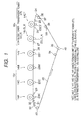
- 14CT, 14LG_K, 14Y, 14M, 14C, 14K image forming unit of transparent toner (CT), low-gloss black (LG_K), yellow (Y), magenta (M), cyan (C), black (K), 22: intermediate transfer belt, and 100: control unit.
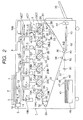
- Fig. 2 is a schematic configuration diagram showing a tandem type digital color printer as an image forming apparatus according to a first exemplary embodiment of the invention.
- the tandem type digital color printer has an image reading unit and also serves as a full color copying machine or a facsimile machine.
- the image forming apparatus does not have to have the image reading unit, but may form an image based on image data output from a not-shown personal computer or the like.
- the reference numeral 1 represents a tandem type digital color printer body.
- the digital color printer body 1 has an image reading unit 3 in an upper portion of its one side (left in the illustrated example).
- the image reading unit 3 reads an image of a document 2.
- An image processing unit 4 and an image output unit 5 are disposed inside the color printer body 1.
- the image processing unit 4 performs predetermined image processing upon image data output from the image reading unit 3, a not-shown personal computer or the like, or image data transmitted through a telephone line, a LAN, or the like.
- the image output unit 5 outputs an image based on the image data on which the predetermined image processing has been performed in the image processing unit 4.
- the image forming operation including an image forming position in the image output unit 5 is controlled by a control circuit 100 serving as a control section.
- the image reading unit 3 is configured as follows. A platen cover 6 is opened and closed to mount the document 2 on a platen glass 7. The document 2 mounted on the platen glass 7 is lit by a light source 8, while an image of reflected light from the document 2 is scanned and exposed on an image reading element 13 through a reduction scanning optical system constituted by a full-rate mirror 9, half mirrors 10 and 11 and an imaging lens 12.
- the image reading element 13 is constituted by a CCD or the like. The image of the document 2 is read with a predetermined dot density by the image reading element 13.
- the image of the document 2 read by the image reading unit 3 is sent to the image processing unit 4 as document reflectance data of three colors such as red (R), green (G) and blue (B) (e.g. 8 bit for each color).
- predetermined image processing such as shading correction, position error correction, brightness/color-space conversion, gamma correction, frame elimination, color/movement editing, etc. is performed on the reflectance data of the document 2.
- the image data on which the predetermined image processing has been performed in the image processing unit 4 are converted into image data of four colors, yellow (Y), magenta (M), cyan (C) and black (K), and converted into image data of six colors by adding image data of low-gloss black (LG_K) and transparent toner (CT) thereto, by the same image processing unit 4.
- the image data of six colors are output to the image output unit 5 which will be described next.
- the image output unit 5 has six, first to sixth, image forming units (image forming sections) 14 1 , 14 2 , 14 3 , 14 4 , 14 5 and 14 6 arranged in accordance with image formation order.
- the first to sixth image forming units 14 1 , 14 2 , 14 3 , 14 4 , 14 5 and 14 6 are divided into a first image forming unit group 15 1 consisting of the two image forming units 14 1 and 14 2 on the upstream side in the image formation order, and a second image forming unit group 15 2 consisting of the four image forming units 14 3 , 14 4 , 14 5 and 14 6 on the downstream side.
- Each unit of the first image forming unit group 15 1 located on the upstream side is an ERU (Engineering Replacement Unit) which can be replaced by a service engineer in accordance with user's demand.
- ERU Engineing Replacement Unit
- the second image forming unit group 15 2 is constituted by image forming units 14Y, 14M, 14C and 14K for forming four color images of yellow (Y), magenta (M), cyan (C) and black (K).
- images are formed with color toners in the yellow (Y), magenta (M) and cyan (C) image forming units 14Y, 14M and 14C, while an image is formed with a high-gloss black toner in the black (K) image forming unit 14K.
- image forming units 14CT and 14LG_K using a transparent toner (CT) and a low-gloss black (LG_K) toner with low glossiness are used as the first image forming unit group 15 1 .
- the transparent toner (CT) is used for improving transfer properties of a toner image when a recording medium having irregularities on the surface, such as embossed paper or rough paper, is used, or for giving gloss to a color image.
- the transparent toner (CT) is formed to be laminated as a lower portion (lower layer) on an intermediate transferer than color images of yellow (Y), magenta (M), cyan (C), black (K), etc. formed by the second image forming unit group 15 2 .
- the low-gloss black (LG_K) toner is used for forming a low-gloss black image when a character image or an image of graphic art or the like is formed.
- the low-gloss black (LG_K) toner is, for example, made of a low molecular-weight synthetic resin material such as polyester resin.
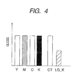
- the low-gloss black (LG_K) toner forms a black image whose glossiness is remarkably lower (for example, about 1/2) than that of the transparent toner (CT) or any other color toner of yellow (Y), magenta (M), cyan (C) or black (K) as shown in Fig. 4 .
- the low-gloss black toner is used as a low-gloss toner with low glossiness
- the invention is not limited thereto, but it is a matter of course that any other color toner of yellow (Y), magenta (M), cyan (C) or the like may be used as the low-gloss toner.
- the image data on which the predetermined image processing has been performed in the image processing unit 4 are converted into image data of six colors in accordance with types of units included in the first image forming unit group 15 1 by the same image processing unit 4.
- the first image forming unit group 15 1 includes the transparent toner (CT) and low-gloss black (LG_K) image forming units 14CT and 14LG_K
- the image data are converted into image data of transparent toner (CT), low-gloss black (LG_K), yellow (Y), magenta (M), cyan (C) and black (K).
- image processing operation of the image processing unit 4 is controlled by the control unit 100.
- image data of transparent toner (CT) is formed, for example, with fixed density in regions where image data of any other color, yellow (Y), magenta (M), cyan (C) or black (K) than low-gloss black (LG_K) are present.
- Image processing is performed so that image data of transparent toner (CT) are absent from regions corresponding to image data of low-gloss black (LG_K).
- a toner cartridge for replenishing toner to a developing unit of the image forming unit is also replaced simultaneously in order to prevent the toner from being mixed with any other color toner.
- the six image forming units 14CT, 14LG_K, 14Y, 14M, 14C and 14K of transparent toner (CT), low-gloss black (LG_K), yellow (Y), magenta (M), cyan (C) and black (K) are disposed in parallel at predetermined horizontal intervals in accordance with user's demand, as shown in Fig. 2 .
- each image forming unit has a photoconductor drum 16, a primary charging scorotron 17, an image exposure unit 18, a developing unit 19 and a cleaner unit 20.
- the photoconductor drum 16 is an image carrier that is driven to rotate in a predetermined velocity along the arrow A direction.
- the scorotron 17 charges the surface of the photoconductor drum 16 uniformly.
- the image exposure unit 18 is an image writing section that performs image exposure upon the surface of the photoconductor drum 16 based on image data corresponding to each color so as to form an electrostatic latent image.
- the developing unit 19 develops, with toner, the electrostatic latent image formed on the photoconductor drum 16.
- the cleaning unit 20 removes residual materials such as toner staying behind on the surface of the photoconductor drum 16.
- the image forming units 14CT and 14LG_K are arranged to be replaceable as mentioned above, while their image exposure units 18 are placed not replaceably but fixedly because the image exposure units 18 do not depend on the colors formed by the image forming units 14CT and 14LG_K.
- image data of corresponding colors are sequentially output from the image processing unit 4 to the image exposure units 18CT, 18LG_K, 18Y, 18M, 18C and 18K of the six image forming units 14CT, 14LG_K, 14Y, 14M, 14C and 14K of transparent toner (CT), low-gloss black (LG_K), yellow (Y), magenta (M), cyan (C) and black (K).
- CT transparent toner
- LG_K low-gloss black
- Y yellow
- M magenta
- C cyan
- K black
- the surfaces of the photoconductor drums 16CT, 16LG_K, 16Y, 16M, 16C and 16K are scanned and exposed with laser beams LB emitted from the corresponding image exposure units 18CT, 18LG_K, 18Y, 18M, 18C and 18K in accordance with the corresponding image data respectively, so that electrostatic latent images corresponding to the image data are formed on the surfaces of the photoconductor drums 16CT, 16LG_K, 16Y, 16M, 16C and 16K.
- the electrostatic latent images formed thus on the surfaces of the photoconductor drums 16CT, 16LG_K, 16Y, 16M, 16C and 16K are developed as toner images of transparent toner (CT), low-gloss black (LG_K), yellow (Y), magenta (M), cyan (C) and black (K) by the developing units 19CT, 19LG_K, 19Y, 19M, 19C and 19K respectively.
- the toner images of transparent toner (CT), low-gloss black (LG_K), yellow (Y), magenta (M), cyan (C) and black (K) sequentially formed on the photoconductor drums 16CT, 16LG_K, 16Y, 16M, 16C and 16K of the image forming units 14CT, 14LG_K, 14Y, 14M, 14C and 14K are primarily transferred onto an intermediate transfer belt 22 in primary transfer positions N1 by primary transfer rolls 23CT, 23LG_K, 23Y, 23M, 23C and 23K so as to be put on top of one another in accordance with the color of an image to be formed.
- the primary transfer rolls 23CT, 23LG_K, 23Y, 23M, 23C and 23K serve as primary transfer sections.
- the intermediate transfer belt 22 is an intermediate transferer shaped like an endless belt, and disposed under the image forming units 14CT, 14LG_K, 14Y, 14M, 14C and 14K.
- the intermediate transfer belt 22 is hung and looped with a fixed tension among a driving roll 24, a first retract roll 25, a first fixed roll 26, a second retract roll 27, a third retract roll 28, a fourth retract roll 29, a fifth retract roll 30, a second fixed roll 31, a center roll 32, a tension applying roll 33, a prior-to-secondary-transfer roll 34, a back support roll 35, an adj ustment roll 36, a first cleaning roll 37 and a second cleaning roll 38.
- the intermediate transfer belt 22 is driven to circulate with a predetermined moving velocity along the arrow B direction by the driving roll 24 which is driven to rotate by a not-shown dedicated driving motor having an excellent velocity constancy.
- a flexible synthetic resin film of polyimide, polyamide-imide or the like formed into an endless belt shape is used as the intermediate transfer belt 22.
- the first to fifth retract rolls 25, 27, 28, 29 and 30 are moved by a not-shown moving section in accordance with the color of an image to be formed, so as to contact with or leave the photoconductor drums 16CT, 16LG_K, 16Y, 16M, 16C and 16K together with the primary transfer rolls 23CT, 23LG_K, 23Y, 23M, 23C and 23K respectively.
- the reference sign S1 represents a first image forming section of the first image forming unit group
- S2 represents a second image forming section of the first image forming unit group.
- the reference signs R1 to R5 represent the first to fifth retract rolls respectively, and UP and DOWN designate the state where the retract roll contacts with a corresponding photoconductor drum and the state where the retract roll leaves the corresponding photoconductor drum, respectively.
- the toner images of transparent toner (CT), low-gloss black (LG_K), yellow (Y), magenta (M), cyan (C) and black (K) transferred in multiple layers onto the intermediate transfer belt 22 are secondarily transferred onto a recording sheet of paper 41 due to an electrostatic force in a secondary transfer position N2 by a transfer bias applied between the back support roll 35 and a secondary transfer roll 40.
- the secondary transfer roll 40 is a secondary transfer section.
- the recording sheet of paper 41 is a recording medium.
- the recording sheet of paper 41 on which the toner images in accordance with the color of an image to be formed have been transferred is conveyed to the fixing unit 44 by two conveyor belts 42 and 43.
- the recording sheet of paper 41 on which the toner images of the respective colors have been transferred is subjected to a fixing process with heat and pressure by the fixing unit 44.
- the recording sheet of paper 41 is discharged onto a discharge tray 45 provided outside the printer body 1.
- recording sheets of paper 41 with a desired size and material are separated and fed one by one from a paper feed tray 46 by a paper feed roll 47 and a pair of paper separation rolls 48 and 49, and once conveyed to registration rolls 52 through a paper conveyance path 51 where conveyance rolls 50 are disposed.
- the paper feed tray 46 is disposed in a bottom portion of the printer body 1.
- Each recording sheet of paper 41 fed from the paper feed tray 46 is sent out to the secondary transfer position N2 by the registration rolls 52 in synchronization with the toner images on the intermediate transfer belt 22.
- the registration rolls 52 are driven to rotate at predetermined timing.
- a large number of recording sheets of paper 41 can be fed from each paper feed tray 46. It is a matter of course that normal paper can be fed as the recording paper 41. In addition to the normal paper, other recording media having irregularities on their surfaces, such as embossed paper and rough paper, can be fed as the recording paper 41.
- residual toners etc. are removed from the photoconductor drums 16CT, 16LG_K, 16Y, 16M, 16C and 16K by cleaning units 20CT, 20LG_K, 20Y, 20M, 20C and 20K. Then, the photoconductor drums 16CT, 16LG_K, 16Y, 16M, 16C and 16K are ready for the next image forming process.
- residual toners, paper dust, etc. are removed from the intermediate transfer belt 22 by the first cleaning roll 37, the second cleaning roll 38 and not-shown cleaning brushes or cleaning blades opposed to the first and second cleaning rolls 37 and 38 through the intermediate transfer belt 22.
- the reference numeral 53 represents a cleaning brush for cleaning the inner surface of the intermediate transfer belt 22.
- the first image forming unit group 15 1 can be replaced in accordance with user's demand as described above.
- the transparent toner (CT) image forming unit 14CT and the low-gloss black (LG_K) image forming unit 14LG_K are used as the first image forming unit group 15 1 .
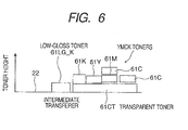
- the transparent toner (CT) image forming unit 14CT forms a toner image 61CT out of the transparent toner (CT) uniformly with predetermined density all over the image region except an image region for a toner image 61LG_K of low-gloss black (LG_K), for example, as shown in Fig. 6 .
- a toner image 61LG_K of low-gloss black (LG_K) for example, as shown in Fig. 6 .
- LG_K low-gloss black
- toner images 61Y, 61M, 61C and 61K of full color or the like are formed on the intermediate transfer belt 22 on which the toner image 61CT of the transparent toner (CT) has been uniformly formed by the transparent toner (CT) image forming unit 14CT.
- the low-gloss black (LG_K) image forming unit 14LG_K located on the downstream side of the transparent toner (CT) image forming unit 14CT serves to form an image of low-gloss black (LG_K). Therefore, the image of the transparent toner (CT) is not formed in the position for the image of low-gloss black (LG_K).
- the digital color printer having the aforementioned configuration according to this embodiment it is possible to prevent gloss from occurring in an image of a low-gloss toner with low glossiness due to a transparent toner transferred under the low-gloss toner on an intermediate transferer when an image is formed using the low-gloss toner and the transparent toner in the intermediate transfer type image forming units. Description about this point will be given next.
- the digital color printer has the six image forming units 14CT, 14LG_K, 14Y, 14M, 14C and 14K of transparent toner (CT), low-gloss black (LG_K), yellow (Y), magenta (M), cyan (C) and black (K).
- CT transparent toner
- LG_K low-gloss black
- Y yellow
- M magenta
- C cyan
- K black
- the transparent toner (CT) image forming unit 14CT is mounted on the most upstream position of the first image forming unit group 15 1
- the low-gloss black (LG_K) image forming unit 14LG_K is mounted on the downstream side of the transparent toner (CT) image forming unit 14CT.
- the control unit 100 detects that the transparent toner (CT) and low-gloss black (LG_K) image forming units 14CT and 14LG_K have been mounted in the first image forming unit group 15 1 .
- image data are converted into not only yellow (Y) image data, magenta (M) image data, cyan (C) image data and black (K) image data but also low-gloss black (LG_K) image data and transparent toner (CT) image data.
- the transparent toner (CT) image data are set with fixed density all over the same regions as the respective yellow (Y), magenta (M), cyan (C) and black (K) image data excluding the low-gloss black (LG_K) image data.
- image data of corresponding colors are sequentially output to the image exposure units 18CT, 18LG_K, 18Y, 18M, 18C and 18K of the six image forming units 14CT, 14LG_K, 14Y, 14M, 14C and 14K of transparent toner (CT), low-gloss black (LG_K), yellow (Y), magenta (M), cyan (C) and black (K).
- CT transparent toner
- LG_K low-gloss black
- M yellow
- M magenta
- C cyan
- K black
- the surfaces of the photoconductor drums 16CT, 16LG_K, 16Y, 16M, 16C and 16K are scanned and exposed with laser beams LB emitted from the corresponding image exposure units 18CT, 18LG_K, 18Y, 18M, 18C and 18K in accordance with the corresponding image data respectively, so that electrostatic latent images are formed on the surfaces of the photoconductor drums 16CT, 16LG_K, 16Y, 16M, 16C and 16K.
- the electrostatic latent images formed thus on the surfaces of the photoconductor drums 16CT, 16LG_K, 16Y, 16M, 16C and 16K are developed as toner images of transparent toner (CT), low-gloss black (LG_K), yellow (Y), magenta (M), cyan (C) and black (K) by the developing units 19CT, 19LG_K, 19Y, 19M, 19C and 19K respectively.
- CT transparent toner
- LG_K low-gloss black
- the low-gloss black (LG_K) image forming unit 14LG_K forms a black image which has the same color as the black (K) image forming unit 14K but which is a low-gloss black image with low glossiness unlike the black (K) image forming unit 14K. Normally, therefore, the black (K) image is not formed above the low-gloss black image. In this embodiment, however, even if the black (K) image is present above the low-gloss black image on the intermediate transfer belt 22, the low-gloss black image is located above the black (K) image after being transferred onto a recording medium. Therefore, the black (K) image may be formed above the low-gloss black image.
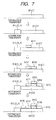
- the toner images of the respective colors formed by the six transparent toner (CT), low-gloss black (LG_K), yellow (Y), magenta (M), cyan (C) and black (K) image forming units 14CT, 14LG_K, 14Y, 14M, 14C and 14K as described above are sequentially primarily transferred onto the intermediate transfer belt 22 as shown in Fig. 7 .
- the transparent toner (CT), low-gloss black (LG_K), yellow (Y), magenta (M), cyan (C) and black (K) toner images primarily transferred onto the intermediate transfer belt 22 are collectively secondarily transferred onto the recording sheet of paper 41 in the secondary transfer position N2, and fixed by the fixing unit 44.
- a full color image or the like is formed.
- the toner image of the transparent toner (CT) which has been first transferred onto the intermediate transfer belt 22 is located in the lowermost portion, and the toner images of yellow (Y), magenta (M), cyan (C) and black (K) are located on the toner image of the transparent toner (CT), as shown in Fig. 7 .
- the recording sheet of paper 41 when a sheet of embossed paper, rough paper or the like with irregularities on its surface is used as the recording sheet of paper 41 so that an electrostatic transfer force is relatively weak in a groove portion of the embossed paper or the like in the secondary transfer of the transparent toner (CT), low-gloss black (LG_K), yellow (Y), magenta (M), cyan (C) and black (K) toner images from the intermediate transfer belt 22 onto the recording sheet of paper 41, the image of the transparent toner (CT) is present on the surface of the intermediate transfer belt 22 having a higher adhesive force than the adhesive force between toner particles so that a part of the toner image of the transparent toner (CT) may stay behind on the surface of the intermediate transfer belt 22 as shown in Fig. 8 . Even in that case, the other toner images of yellow (Y), magenta (M), cyan (C) and black (K) can be secondarily transferred onto the recording sheet of paper 41 surely.
- CT transparent toner
- LG_K low-glo
- the transparent toner (CT) is absent under the low-gloss black (LG_K) toner image.
- LG_K low-gloss black
- LG_K low-gloss black
- the low-gloss black (LG_K) toner image can be secondarily transferred excellently.
- the transparent toner (CT) due to the absence of the transparent toner (CT), there is no fear that gloss is given unwillingly, but a character image or an image of graphic art or the like can be formed with the low-gloss black (LG_K) toner excellently.
- the image quality can be improved.
- Fig. 9 shows a second exemplary embodiment of the invention. Description will be made with reference to Fig. 9 , in which parts the same as those in the previous embodiment are referred to by the same numerals.
- a plurality of image forming sections and an intermediate transferer are provided.
- an image forming section that forms an image of a low-gloss toner with lower glossiness than that of any other color toner is disposed more upstream in image formation order than an image forming section that forms an image of a transparent toner.
- a plurality of toner images formed by the image forming sections is transferred onto the intermediate transferer so that the image of the transparent toner is not transferred under the image of the low-gloss toner.
- a low-gloss black (LG_K) image forming unit 14LG_K and a transparent toner (CT) image forming unit 14CT are provided as a first image forming unit group 15 1 .
- the low-gloss black (LG_K) image forming unit 14LG_K is disposed on the most upstream side in image formation order, and the transparent toner (CT) image forming unit 14CT is disposed on the downstream side of the low-gloss black (LG_K) image forming unit 14LG_K.
- image forming units 14Y, 14M, 14C and 14K of yellow (Y), magenta (M), cyan (C) and black (K) are disposed in this order as a second image forming unit group 15 2 in the same manner as in the first exemplary embodiment.
- the second exemplary embodiment is different from the first exemplary embodiment in that an image of transparent toner (CT) is formed all over the image region including the image region of the low-gloss black (LG_K) image forming unit 14LG_K in the transparent toner (CT) image forming unit 14CT.
- CT transparent toner
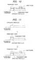
- the low-gloss black (LG_K) image forming unit 14LG_K is disposed on the most upstream side in the image formation order. Accordingly, even if the transparent toner (CT) image is formed all over the image region including the image region of the low-gloss black (LG_K) image forming unit 14LG_K in the transparent toner (CT) image forming unit 14CT, there is no fear that the transparent toner (CT) image is formed under the low-gloss black (LG_K) image on the intermediate transfer belt 22, as shown in Fig. 11 .
- LG_K low-gloss black
- the transparent toner (CT) image is present under the low-gloss black (LG_K) image on the recording sheet of paper 41. Accordingly, there is no fear that gloss is given unwillingly by the transparent toner (CT) image, but a character image or an image of graphic art or the like of the low-gloss black (LG_K) toner can be formed excellently. Thus, the image quality can be improved.
- a so-called tandem type image forming apparatus provided with a plurality of image forming sections has been described in the first exemplary embodiment.
- the invention can be also applied to a so-called multi-cycle image forming apparatus.
- the image forming apparatus has only one image carrier, while electrostatic latent images formed on the image carrier are developed with respective color toners of transparent toner (CT), low-gloss black (LG_K), yellow (Y), magenta (M), cyan (C) and black (K) sequentially.
- CT transparent toner
- LG_K low-gloss black
- Y yellow
- M magenta
- C cyan
- K black
Landscapes
- Physics & Mathematics (AREA)
- General Physics & Mathematics (AREA)
- Color Electrophotography (AREA)
Applications Claiming Priority (1)
| Application Number | Priority Date | Filing Date | Title |
|---|---|---|---|
| JP2009078300A JP4883119B2 (ja) | 2009-03-27 | 2009-03-27 | 画像形成装置 |
Publications (1)
| Publication Number | Publication Date |
|---|---|
| EP2241941A2 true EP2241941A2 (de) | 2010-10-20 |
Family
ID=42709086
Family Applications (1)
| Application Number | Title | Priority Date | Filing Date |
|---|---|---|---|
| EP10156676A Withdrawn EP2241941A2 (de) | 2009-03-27 | 2010-03-16 | Bilderzeugungsvorrichtung |
Country Status (3)
| Country | Link |
|---|---|
| US (1) | US20100247129A1 (de) |
| EP (1) | EP2241941A2 (de) |
| JP (1) | JP4883119B2 (de) |
Families Citing this family (2)
| Publication number | Priority date | Publication date | Assignee | Title |
|---|---|---|---|---|
| JP2012063399A (ja) * | 2010-09-14 | 2012-03-29 | Ricoh Co Ltd | 画像形成装置 |
| US9417546B2 (en) | 2014-06-02 | 2016-08-16 | Kabushiki Kaisha Toshiba | Image forming apparatus and image forming method for forming a transparent toner image and a color image |
Citations (2)
| Publication number | Priority date | Publication date | Assignee | Title |
|---|---|---|---|---|
| JP2006337655A (ja) | 2005-06-01 | 2006-12-14 | Canon Inc | 画像形成装置及び画像形成方法 |
| JP2008112087A (ja) | 2006-10-31 | 2008-05-15 | Canon Inc | 画像形成装置 |
Family Cites Families (10)
| Publication number | Priority date | Publication date | Assignee | Title |
|---|---|---|---|---|
| US5160969A (en) * | 1989-06-26 | 1992-11-03 | Ricoh Company, Ltd. | Image forming apparatus having a separate black developer stored for a color image |
| DE69119549T2 (de) * | 1990-11-14 | 1996-11-28 | Konishiroku Photo Ind | Farbbilderzeugungsverfahren |
| JP2584896B2 (ja) * | 1990-11-30 | 1997-02-26 | キヤノン株式会社 | 画像形成装置 |
| JPH07129039A (ja) * | 1993-11-08 | 1995-05-19 | Hitachi Ltd | 画像形成装置 |
| US5613176A (en) * | 1996-03-25 | 1997-03-18 | Xerox Corporation | Image on image process color with two black development steps |
| JP2002082508A (ja) * | 2000-09-05 | 2002-03-22 | Casio Electronics Co Ltd | 画像形成装置 |
| JP2002116631A (ja) * | 2000-10-04 | 2002-04-19 | Konica Corp | 画像形成装置 |
| JP2002202645A (ja) * | 2000-10-30 | 2002-07-19 | Ricoh Co Ltd | カラー画像形成方法 |
| US20030099007A1 (en) * | 2001-11-29 | 2003-05-29 | Towner David K. | Selectable gloss levels and placement |
| US20060114481A1 (en) * | 2004-11-30 | 2006-06-01 | Xerox Corporation | Object-oriented ink selection |
-
2009
- 2009-03-27 JP JP2009078300A patent/JP4883119B2/ja not_active Expired - Fee Related
- 2009-09-02 US US12/552,406 patent/US20100247129A1/en not_active Abandoned
-
2010
- 2010-03-16 EP EP10156676A patent/EP2241941A2/de not_active Withdrawn
Patent Citations (2)
| Publication number | Priority date | Publication date | Assignee | Title |
|---|---|---|---|---|
| JP2006337655A (ja) | 2005-06-01 | 2006-12-14 | Canon Inc | 画像形成装置及び画像形成方法 |
| JP2008112087A (ja) | 2006-10-31 | 2008-05-15 | Canon Inc | 画像形成装置 |
Also Published As
| Publication number | Publication date |
|---|---|
| JP2010230971A (ja) | 2010-10-14 |
| JP4883119B2 (ja) | 2012-02-22 |
| US20100247129A1 (en) | 2010-09-30 |
Similar Documents
| Publication | Publication Date | Title |
|---|---|---|
| EP1574345B1 (de) | Verfahren zum Erfassen einer Positionsabweichung und Bilderzeugungsvorrichtung | |
| US8503919B2 (en) | Image forming apparatus for controlling image clarity using clear toner | |
| JP4883120B2 (ja) | 画像形成装置 | |
| JP6029264B2 (ja) | 転写装置及び画像形成装置 | |
| EP2241941A2 (de) | Bilderzeugungsvorrichtung | |
| JP2009222810A (ja) | 定着装置及びこれを備えた画像形成装置 | |
| JP4431595B2 (ja) | 画像形成装置、画像形成方法、画像処理プログラムおよび画像処理プログラムを記録した記録媒体 | |
| JP2002139883A (ja) | 画像形成装置と画像形成方法及び付加情報画像の判別方法 | |
| JP4820687B2 (ja) | カラー画像形成装置 | |
| CN206606793U (zh) | 原稿供给装置及图像形成装置 | |
| CN101030058B (zh) | 图像形成装置 | |
| JP2010217714A (ja) | 画像形成装置 | |
| JP6930175B2 (ja) | 転写装置および画像形成装置 | |
| JP4019626B2 (ja) | 画像形成装置 | |
| JP6241498B2 (ja) | 転写装置及び画像形成装置 | |
| JP4230163B2 (ja) | 光書込み装置の階調補正方法およびこれを用いた画像形成装置 | |
| JP2010210682A (ja) | 画像形成装置 | |
| JP2013092696A (ja) | 画像処理方法、画像処理装置及び画像形成装置 | |
| JP4006942B2 (ja) | 画像形成装置 | |
| JP5648516B2 (ja) | 粉体回収容器の満杯検知装置及びこれを用いた粉体回収装置、並びに画像形成装置 | |
| JPH0460568A (ja) | 画像形成装置 | |
| JP2002040743A (ja) | 画像形成装置 | |
| JP2004117896A (ja) | 画像形成装置及び画像形成方法 | |
| JP5790137B2 (ja) | 画像処理方法 | |
| JP4586597B2 (ja) | 画像形成装置及び画像形成方法 |
Legal Events
| Date | Code | Title | Description |
|---|---|---|---|
| PUAI | Public reference made under article 153(3) epc to a published international application that has entered the european phase |
Free format text: ORIGINAL CODE: 0009012 |
|
| AK | Designated contracting states |
Kind code of ref document: A2 Designated state(s): AT BE BG CH CY CZ DE DK EE ES FI FR GB GR HR HU IE IS IT LI LT LU LV MC MK MT NL NO PL PT RO SE SI SK SM TR |
|
| AX | Request for extension of the european patent |
Extension state: AL BA ME RS |
|
| STAA | Information on the status of an ep patent application or granted ep patent |
Free format text: STATUS: THE APPLICATION HAS BEEN WITHDRAWN |
|
| 18W | Application withdrawn |
Effective date: 20140117 |