EP2241709A2 - Vorrichtung zur gleichzeitigen Bewegung von Schiebetüren - Google Patents
Vorrichtung zur gleichzeitigen Bewegung von Schiebetüren Download PDFInfo
- Publication number
- EP2241709A2 EP2241709A2 EP10380056A EP10380056A EP2241709A2 EP 2241709 A2 EP2241709 A2 EP 2241709A2 EP 10380056 A EP10380056 A EP 10380056A EP 10380056 A EP10380056 A EP 10380056A EP 2241709 A2 EP2241709 A2 EP 2241709A2
- Authority
- EP
- European Patent Office
- Prior art keywords
- cogged
- sliding
- belt
- cogged belt
- simultaneous displacement
- Prior art date
- Legal status (The legal status is an assumption and is not a legal conclusion. Google has not performed a legal analysis and makes no representation as to the accuracy of the status listed.)
- Granted
Links
Images


Classifications
-
- E—FIXED CONSTRUCTIONS
- E05—LOCKS; KEYS; WINDOW OR DOOR FITTINGS; SAFES
- E05F—DEVICES FOR MOVING WINGS INTO OPEN OR CLOSED POSITION; CHECKS FOR WINGS; WING FITTINGS NOT OTHERWISE PROVIDED FOR, CONCERNED WITH THE FUNCTIONING OF THE WING
- E05F17/00—Special devices for shifting a plurality of wings operated simultaneously
- E05F17/004—Special devices for shifting a plurality of wings operated simultaneously for wings which abut when closed
-
- E—FIXED CONSTRUCTIONS
- E05—LOCKS; KEYS; WINDOW OR DOOR FITTINGS; SAFES
- E05F—DEVICES FOR MOVING WINGS INTO OPEN OR CLOSED POSITION; CHECKS FOR WINGS; WING FITTINGS NOT OTHERWISE PROVIDED FOR, CONCERNED WITH THE FUNCTIONING OF THE WING
- E05F15/00—Power-operated mechanisms for wings
- E05F15/60—Power-operated mechanisms for wings using electrical actuators
- E05F15/603—Power-operated mechanisms for wings using electrical actuators using rotary electromotors
- E05F15/632—Power-operated mechanisms for wings using electrical actuators using rotary electromotors for horizontally-sliding wings
- E05F15/643—Power-operated mechanisms for wings using electrical actuators using rotary electromotors for horizontally-sliding wings operated by flexible elongated pulling elements, e.g. belts, chains or cables
-
- E—FIXED CONSTRUCTIONS
- E05—LOCKS; KEYS; WINDOW OR DOOR FITTINGS; SAFES
- E05F—DEVICES FOR MOVING WINGS INTO OPEN OR CLOSED POSITION; CHECKS FOR WINGS; WING FITTINGS NOT OTHERWISE PROVIDED FOR, CONCERNED WITH THE FUNCTIONING OF THE WING
- E05F17/00—Special devices for shifting a plurality of wings operated simultaneously
- E05F17/002—Special devices for shifting a plurality of wings operated simultaneously for wings which lie one behind the other when closed
-
- E—FIXED CONSTRUCTIONS
- E05—LOCKS; KEYS; WINDOW OR DOOR FITTINGS; SAFES
- E05D—HINGES OR SUSPENSION DEVICES FOR DOORS, WINDOWS OR WINGS
- E05D15/00—Suspension arrangements for wings
- E05D15/06—Suspension arrangements for wings for wings sliding horizontally more or less in their own plane
- E05D15/08—Suspension arrangements for wings for wings sliding horizontally more or less in their own plane consisting of two or more independent parts movable each in its own guides
-
- E—FIXED CONSTRUCTIONS
- E05—LOCKS; KEYS; WINDOW OR DOOR FITTINGS; SAFES
- E05Y—INDEXING SCHEME ASSOCIATED WITH SUBCLASSES E05D AND E05F, RELATING TO CONSTRUCTION ELEMENTS, ELECTRIC CONTROL, POWER SUPPLY, POWER SIGNAL OR TRANSMISSION, USER INTERFACES, MOUNTING OR COUPLING, DETAILS, ACCESSORIES, AUXILIARY OPERATIONS NOT OTHERWISE PROVIDED FOR, APPLICATION THEREOF
- E05Y2201/00—Constructional elements; Accessories therefor
- E05Y2201/20—Brakes; Disengaging means; Holders; Stops; Valves; Accessories therefor
- E05Y2201/214—Disengaging means
- E05Y2201/216—Clutches
-
- E—FIXED CONSTRUCTIONS
- E05—LOCKS; KEYS; WINDOW OR DOOR FITTINGS; SAFES
- E05Y—INDEXING SCHEME ASSOCIATED WITH SUBCLASSES E05D AND E05F, RELATING TO CONSTRUCTION ELEMENTS, ELECTRIC CONTROL, POWER SUPPLY, POWER SIGNAL OR TRANSMISSION, USER INTERFACES, MOUNTING OR COUPLING, DETAILS, ACCESSORIES, AUXILIARY OPERATIONS NOT OTHERWISE PROVIDED FOR, APPLICATION THEREOF
- E05Y2201/00—Constructional elements; Accessories therefor
- E05Y2201/60—Suspension or transmission members; Accessories therefor
- E05Y2201/606—Accessories therefor
- E05Y2201/62—Synchronisation of suspension or transmission members
-
- E—FIXED CONSTRUCTIONS
- E05—LOCKS; KEYS; WINDOW OR DOOR FITTINGS; SAFES
- E05Y—INDEXING SCHEME ASSOCIATED WITH SUBCLASSES E05D AND E05F, RELATING TO CONSTRUCTION ELEMENTS, ELECTRIC CONTROL, POWER SUPPLY, POWER SIGNAL OR TRANSMISSION, USER INTERFACES, MOUNTING OR COUPLING, DETAILS, ACCESSORIES, AUXILIARY OPERATIONS NOT OTHERWISE PROVIDED FOR, APPLICATION THEREOF
- E05Y2201/00—Constructional elements; Accessories therefor
- E05Y2201/60—Suspension or transmission members; Accessories therefor
- E05Y2201/622—Suspension or transmission members elements
- E05Y2201/644—Flexible elongated pulling elements
- E05Y2201/652—Belts
-
- E—FIXED CONSTRUCTIONS
- E05—LOCKS; KEYS; WINDOW OR DOOR FITTINGS; SAFES
- E05Y—INDEXING SCHEME ASSOCIATED WITH SUBCLASSES E05D AND E05F, RELATING TO CONSTRUCTION ELEMENTS, ELECTRIC CONTROL, POWER SUPPLY, POWER SIGNAL OR TRANSMISSION, USER INTERFACES, MOUNTING OR COUPLING, DETAILS, ACCESSORIES, AUXILIARY OPERATIONS NOT OTHERWISE PROVIDED FOR, APPLICATION THEREOF
- E05Y2900/00—Application of doors, windows, wings or fittings thereof
- E05Y2900/10—Application of doors, windows, wings or fittings thereof for buildings or parts thereof
- E05Y2900/13—Type of wing
- E05Y2900/132—Doors
Definitions
- the present invention refers to a simultaneous displacement device for sliding doors comprising, both two sliding leaf which slide in the same direction and sense and three and four sliding leaves which slide in the opposite direction to the two first leaves in a synchronized manner. All the main elements which configure the device are integrated in an upper guide with easy installation and mounting.
- the present invention is especially suitable for applying it in glass sliding doors which are manually run with respect to fixed enclosures or panels which frame an open passage area assisted by said door.
- the first sliding leaf is hung from an upper guide through a couple of moving carriages which slide inside it and from which there hang skids integral to a bearing profile holding said leaf.
- the second sliding leaf is hung in the same way through a second upper guide parallel to the first leaf.
- the first one of them features a cogged belt arranged between two pulleys integral to the bearing profile. Each one of the pulleys is located at one of the side ends of the first sliding leaf, so that the belt extends along the whole width thereof.
- the belt is engaged at a fixed point of reference, generally a part anchored to the ceiling, next to the upper guides, while the second sliding leaf is engaged to said belt.
- a fixed point of reference generally a part anchored to the ceiling
- the second sliding leaf is engaged to said belt.
- the simultaneous displacement device described above has important limitations and inconveniences.
- the main limitation is that it only allows the simultaneous sliding of two sliding leaves running in the same direction and sense. That is, it does not work with sliding doors the leaves of which run in a synchronized manner in opposite senses.
- This limitation makes the device described above to be intended to a limited number of applications or uses. Specifically, for its application or use in sliding doors which have a relatively small free passage width.
- the mounting complexity of the device described above since it implies both the installation of an upper guide for each one of the two sliding leaves and the installation of the anchoring part of the cogged belt, among other elements.
- the present invention solves the problems described above in a fully satisfactory manner thanks to a device which has great application flexibility and simplicity.
- the device of the present invention allows both the simultaneous displacement of two sliding leaves moving in the same direction and sense, and the simultaneous sliding of three and four sliding leaves running in the opposite sense to that of the two first leaves in a synchronized manner. All main elements configuring the device are integrated in an upper guide with easy installation and mounting.
- the simultaneous displacement device for sliding doors of the present invention is integrated in an upper guide from which there are hung a first and second sliding leaves. Both sliding leaves have the ability to slide in the upper guide direction, thanks to the use of fastening clamps having rolling means which slide on tracks arranged inside said upper guide.
- the device of the present invention comprises a first cogged belt enabled for the union of the first sliding leaf.
- the first cogged belt is established between the first set of cogged pulleys which rotate freely on a first axis and second axis respectively, where said first and second axes are integral to the upper guide.
- the device of the present invention also comprises a second cogged belt enabled for the union of the second sliding leaf and some clutching means.
- the union of the sliding leaves to the cogged belts is carried out through the use of connection parts, which are fixed at one of their ends to clamps while at the other end they hold the belts.
- the second cogged belt is established between a second set of cogged pulleys which rotate freely on the first axis and the second axes respectively.
- the clutching means enable to adopt a first position where the first cogged belt and the second cogged belt move independently, and a second position where the first cogged belt and the second cogged belt move integrally.
- the first position enables the first and second sliding leaves to move separately.
- This first position plays an important role during mounting and maintenance operations. Specifically, it enables to adjust the final position of the sliding doors, once they are fixed to the corresponding cogged belts, thus obtaining the desired overlapping.
- Such overlapping can be produced either between the sliding leaves themselves or between the sliding leaves and the enclosures or fixed panels where they are set.
- the second position enables the first and second sliding leaves to run simultaneously in the same direction and sense; this sense which can be the sense corresponding to the door opening or the one corresponding to the closing of the door.
- the displacement speeds of the first and second sliding leaves adjust for each one of them according to the diameter of the first set of cogged pulleys and to the diameter of the second set of cogged pulleys respectively. Taking the example that the first sliding leaf is the closest to the final point and that its path is half the path of the second sliding leaf, for both of them to start and finish their displacement simultaneously it is necessary for the second one to move at twice the speed of the first. To that end, the pulleys of the first set present half the diameter of the pulleys of the second set.
- the clutching means of the present invention preferably comprise a wheel which rotates freely on one of the axes and which has blocking means which enable to integrate their movement with that of the cogged pulleys arranged in the same axis.
- the wheel is comprised between two cogged pulleys of the same axis.
- the blocking means comprise one or more through holes coinciding with blocking holes drilled on the cogged pulleys, between which at least one through element is inserted, for example, a cotter pin, pin or screw, among other elements.
- the pulleys In order to facilitate the clutching or unclutching of the device, the pulleys have multiple blocking holes forming a circle which is concentric to the pulley axis. Thus, with small rotations applied on the pulleys and on the cogwheel, the blocking holes are easily made to coincide with the through hole.
- the wheel comprises a continuous perimeter groove which engages with one or more protruding elements arranged on the pulleys of the first set or of the second set, without said engaging limiting the relative movement between the wheel and the corresponding pulley, that is, the protruding element slides freely inside the continuous perimeter groove.
- the wheel also comprises one or more discontinuous perimeter grooves, arranged on the opposite face of the continuous perimeter groove, which engage with the protruding elements of the pulleys of the first set or of the second set and which block the relative movement between the wheel and the corresponding pulley.
- the wheel also comprises one or more flexible protruding pivots, the end of which coincides with a plurality of holes arranged concentrically in the pulleys of the first set or of the second set. This enables to precisely face the blocking means to facilitate the insertion of the through element.
- the wheel also comprises a cogged profile.
- the axes can be reinforced by reinforcement pieces which are joined to the lower end of the axis and which present a separating element which avoids the derailment of the second cogged belt.
- the configuration of the previously described simultaneous displacement device for sliding doors is associated to a preferred embodiment, which is non-limiting for the present invention.
- the device of the present invention can be applied in sliding doors having more than two sliding leaves, where all of them have the ability to displace in the same direction and sense. This is attained adding, for each leaf additional to the second, a new cogged belt established between a new set of cogged pulleys which rotate freely on the first axis and the second axis respectively.
- said pulleys are integrated through clutching means such as the one described.
- the displacement speeds of each sliding leaf are adjusted through diameters of each set of cogged pulleys.
- the device comprises a third cogged belt enabled to join a third sliding leaf, said third cogged belt is established between a third set of cogged pulleys which rotate freely on a third and fourth axes, respectively, where said third and fourth axes are integral to the upper guide, being the movement of the third cogged belt synchronized and opposite to the movement of the first cogged belt.
- the device of the present invention comprises a bar integral to the upper guide, arranged in front of the first and third axes at the level of the first cogged belt and of the third cogged belt.
- the aforementioned reinforcement part is joined to the lower end of the first and third axes to provide stiffness to both axes and absorb efforts thereon, ensuring that the gear mechanism enabling the synchronism is maintained at all times.
- the device also comprises a fourth cogged belt enabled to join a fourth sliding leaf and second clutching means.
- the fourth cogged belt is established between a fourth set of cogged pulleys which rotate freely on the third axis and the fourth axis respectively.
- the second clutching means enable to adopt a third position where the third cogged belt and the fourth cogged belt move independently, and a fourth position where the third cogged belt and the fourth cogged belt move integrally to allow the simultaneous displacement of the third sliding leaf and of the fourth sliding leaf.
- Said third and fourth positions are equivalent to the first and second position, respectively.
- the second clutching means comprise a second wheel which rotates freely on the third or fourth axis and which has second blocking means which enable to integrate their movement to that of the cogged pulleys arranged on the same axis.
- the second wheel has the same characteristics than the cogwheel described above.
- the second blocking,means are equivalent to the blocking means described above.
- the synchronism of the third cogged belt and of the first cogged belt, both in the second and in the third embodiments is carried out placing the wheels of the first and second clutching means on the first axis and on the third axis respectively, and engaging the cogged profile of both wheels.
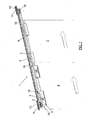
- FIG 1 shows a perspective view of the simultaneous displacement device (1) for sliding doors of the present invention according to a first preferred embodiment.
- the sliding door has a first sliding leaf (7) and a second sliding leaf (8) hung from an upper guide (5), not shown in this figure.
- Both sliding leaves (7) and (8) have the ability to run in the direction of the upper guide (5), thanks to the use of fastening clamps (3) having rolling means (4) which slide on tracks (6) arranged inside said upper guide (5).
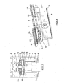
- Figure 2 shows a sectional view of the upper guide (5) where it can be seen how the different components of the present invention are integrated.
- the device (1) of the present invention comprises a first cogged belt (9) enabled for the union of the first sliding leaf (7).
- the first cogged belt (9) is established between a first set of cogged pulleys (11) and (12) which rotate freely-on a first axis (13) and second axis (14) respectively, where said first (13) and second axes (14) are integral to the upper guide (5).
- the device (1) of the present invention also comprises a second cogged belt (10) enabled for the union of the second sliding leaf (8) and some clutching means (2).
- connection parts (18) which are fixed at one of their ends to the clamps (3) while at the other end they hold the corresponding belt (9, 10).
- the second cogged belt (10) is established between a second set of cogged pulleys (15, 16) which rotate freely on the first axis (13) and the second axis (14) respectively.
- the clutching means (2) enable to adopt; a first position where the first cogged belt (9) and the second cogged belt (10) move independently, and a second position where the first cogged belt (9) and the second cogged belt (10) move integrally.
- Figure 3 shows a perspective view of the first axis (13) according to a first preferred embodiment, where it can be seen in greater detail how the different components of said axis (13) are arranged.
- the clutching means (2) are in the second position, that is, they are integral to the first cogged belt (9) and the second cogged belt (10).
- Figure 4 shows a perspective view of the second axis (14) according to a first preferred embodiment, where it can be seen in greater detail how the different components are arranged on said axis (14).
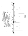
- Figure 5 shows a perspective view of the simultaneous displacement device (1) for sliding doors of the present invention according to a second preferred embodiment.
- the device (1) comprises a third cogged belt (9') enabled to join a third sliding leaf (7'), said third cogged belt (9') being established between a third set of cogged pulleys (11') and (12') which rotate freely on a third (13') and fourth (14') axes, respectively, where said third (13') and fourth (14') axes are integral to the upper guide (5), being the movement of the third cogged pulley (9') synchronized and opposite to the movement of the first cogged pulley (9).
- the first and third sliding leaves (7) and (7') to run in a synchronized manner in opposite senses and simultaneously together with the second sliding leaf (8).
- Figure 6 shows a perspective view of the first axis (13) and the third axis (13') according to a second preferred embodiment, in which it can be seen in greater detail how the elements of both axes (13, 13') interact.
- the device (1) of the present invention comprises a bar (19) integral to the upper guide (5), arranged in front of the first and third axes (13) and (13') at the level of the first cogged belt (9) and of the third cogged belt (9).
- a reinforcement part (32) joined to the lower end of the first and third axes (13) and (13') to provide stiffness to both axes (13, 13') and absorb efforts thereon, ensuring that the gear mechanism enabling the synchronism is maintained at all times.
- the reinforcement part (32) has a separating element (33) which avoids the derailment of the second cogged belt (10).
- Figure 7 shows a perspective view of the fourth axis (14') according to a second referred embodiment, where it can be seen in greater detail how the different components of said axis (14') are arranged.
- Figure 8 shows a perspective view of the simultaneous displacement device (1) for sliding doors of the present invention according to a third preferred embodiment.
- the device (1) comprises a fourth cogged belt (10') enabled to join a fourth sliding leaf (8') and second clutching means (2').
- the fourth cogged belt (10') is established between a fourth set of cogged pulleys (15') and (16') which rotate freely on the third axis (13') and the fourth axis (14') respectively.
- the second clutching means (2') enable to adopt a third position where the third cogged belt (9') and the fourth cogged belt (10') move independently, and a fourth position where the third cogged belt (9') and the fourth cogged belt (10') move integrally to allow the simultaneous displacement of the third sliding leaf (9') and of the fourth sliding leaf (10').
- Figure 9 shows a perspective view of the first axis (13) and of the third axis (13') according to a third preferred embodiment, where it can be seen in greater detail how the elements of both axes (13, 13') interact.
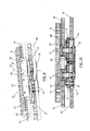
- Figure 10 shows a sectional elevated view of the first axis (13) and of the third axis (13') according to a third preferred embodiment.
- Figure 11 a shows a perspective view of a configuration example of the clutching means (2, 2'), where it can be seen that they comprise a wheel (23, 23') and blocking means (17, 17').
- the blocking means comprise one or more through holes (20) coinciding with blocking holes (27) drilled on the cogged pulleys (11, 11', 12, 12', 15, 15', 16, 16') between which at least one through element (21) is inserted.
- the wheel (23, 23') comprises a continuous perimeter groove (28) which couples with one or more protruding elements (30) arranged on the pulleys (11, 11', 12, 12', 15, 15', 16, 16'), without said coupling limiting the relative movement between the wheel (23, 23') and the corresponding pulley (11, 11', 12, 12', 15, 15', 16, 16'), that is, the protruding element (30) slides freely inside the continuous perimeter groove (28).
- the wheel (23, 23') also comprises one or more discontinuous perimeter grooves (29), arranged on the opposite face of the continuous perimeter groove (28), which couple with the protruding elements (30) of the pulleys (11, 11', 12, 12', 15, 15', 16, 16') and which block the relative movement between the wheel (23, 23') and the corresponding pulley (11, 11', 12, 12', 15, 15', 16, 16').
- Figure 11 b shows a perspective view of a second configuration example of the clutching means (2, 2'), where it can be seen that additionally the wheel also comprises flexible protruding pivots (34), the end of which coincides with a plurality of holes (32) arranged concentrically in the pulleys (11, 11', 12, 12', 15, 15', 16, 16').
- the wheel (23, 23') comprises a cogged profile (34) to enable the synchronism of the third cogged belt (9') and of the first cogged belt (9), both in the second and in the third embodiments, as it can be seen in greater detail in figures 6 and 9 .
- Figures 12a and 12b show two configuration examples of the pulleys of the first and third sets (11, 12) and (11', 12'), where the aforementioned elements can be seen.
- Figures 13a and 13b show two configuration examples of the pulleys of the second and fourth sets (15, 16) and (15', 16'), where the aforementioned elements can be seen.
Landscapes
- Power-Operated Mechanisms For Wings (AREA)
- Transmission Devices (AREA)
- Wing Frames And Configurations (AREA)
Priority Applications (1)
| Application Number | Priority Date | Filing Date | Title |
|---|---|---|---|
| PL10380056T PL2241709T3 (pl) | 2009-04-16 | 2010-04-15 | Jednocześnie przemieszczające urządzenie do drzwi przesuwnych |
Applications Claiming Priority (1)
| Application Number | Priority Date | Filing Date | Title |
|---|---|---|---|
| ES200900999A ES2377631B1 (es) | 2009-04-16 | 2009-04-16 | Dispositivo de desplazamiento simultáneo para puertas correderas. |
Publications (3)
| Publication Number | Publication Date |
|---|---|
| EP2241709A2 true EP2241709A2 (de) | 2010-10-20 |
| EP2241709A3 EP2241709A3 (de) | 2010-12-15 |
| EP2241709B1 EP2241709B1 (de) | 2012-12-05 |
Family
ID=42322739
Family Applications (1)
| Application Number | Title | Priority Date | Filing Date |
|---|---|---|---|
| EP10380056A Active EP2241709B1 (de) | 2009-04-16 | 2010-04-15 | Vorrichtung zur gleichzeitigen Bewegung von Schiebetüren |
Country Status (11)
| Country | Link |
|---|---|
| US (1) | US8424244B2 (de) |
| EP (1) | EP2241709B1 (de) |
| JP (1) | JP5517158B2 (de) |
| BR (1) | BRPI1002525B8 (de) |
| CA (1) | CA2700101C (de) |
| CL (1) | CL2010000348A1 (de) |
| DK (1) | DK2241709T3 (de) |
| ES (2) | ES2377631B1 (de) |
| MX (1) | MX2010004186A (de) |
| PL (1) | PL2241709T3 (de) |
| PT (1) | PT2241709E (de) |
Cited By (5)
| Publication number | Priority date | Publication date | Assignee | Title |
|---|---|---|---|---|
| CN106285304A (zh) * | 2016-09-28 | 2017-01-04 | 广东顶固集创家居股份有限公司 | 双向同步联动装置及双向同步联动门 |
| CN106285305A (zh) * | 2016-09-28 | 2017-01-04 | 广东顶固集创家居股份有限公司 | 同向同步联动装置及同向同步联动门 |
| EP2522800A3 (de) * | 2011-05-13 | 2017-01-25 | GEZE GmbH | Schiebetüranordnung |
| EP3059372B1 (de) | 2014-01-30 | 2017-10-04 | Gebr. Willach GmbH | Teleskopschiebetüranlage |
| EP4350111A4 (de) * | 2022-08-18 | 2024-12-11 | Guangdong OPK Smart Home Technology Co., Ltd. | Montagemechanismus für synchrone bidirektionale verknüpfungstür |
Families Citing this family (12)
| Publication number | Priority date | Publication date | Assignee | Title |
|---|---|---|---|---|
| EP2685034B1 (de) | 2011-03-10 | 2017-01-11 | Nabtesco Corporation | Drehschwenktür |
| ES2393769B1 (es) * | 2011-05-12 | 2013-11-04 | Klein Ibérica, S.A. | Dispositivo de cierre autónomo para puertas correderas. |
| CN102635290A (zh) * | 2012-04-19 | 2012-08-15 | 无锡旭峰门业制造有限公司 | 多叶推拉门同步传动机构 |
| US10196815B2 (en) | 2014-05-28 | 2019-02-05 | Advanced Equipment Corporation | Wall partition movement systems and methods |
| US9359804B2 (en) * | 2014-05-28 | 2016-06-07 | Advanced Equipment Corporation | Wall partition movement systems and methods |
| CN104234588B (zh) * | 2014-09-12 | 2016-05-11 | 黄华央 | 一种推拉门窗 |
| TWM502424U (zh) | 2015-02-10 | 2015-06-11 | Weider Metal Inc | 連結式聯動雙向同步拉動隔間門裝置 |
| US10465383B2 (en) | 2017-01-23 | 2019-11-05 | Advanced Equipment Corporation | Panel storage system and devices |
| US12577823B2 (en) * | 2021-09-27 | 2026-03-17 | Allegion Access Technologies LLC | Multi-panel door system, and dual-synchronization drive assembly for a multi-panel door system |
| KR102531275B1 (ko) * | 2022-04-15 | 2023-05-10 | 고준현 | 연동형 다중 미닫이문 |
| US12227389B2 (en) * | 2023-07-18 | 2025-02-18 | G.A.L. Manufacturing Company, Llc | Telescopic linear operator |
| US12252925B1 (en) * | 2023-09-08 | 2025-03-18 | Electronic Controls Inc. | Sliding door drive system |
Family Cites Families (16)
| Publication number | Priority date | Publication date | Assignee | Title |
|---|---|---|---|---|
| US1534210A (en) * | 1923-06-16 | 1925-04-21 | Tyler Co W S | Operating mechanism for elevator doors |
| US2425016A (en) * | 1944-12-19 | 1947-08-05 | Edgar R Weaver | Hangar door operating mechanism |
| US4259810A (en) * | 1979-07-25 | 1981-04-07 | Westinghouse Electric Corp. | Transit vehicle door control apparatus |
| US4781270A (en) * | 1987-03-02 | 1988-11-01 | Delaware Capital Formation, Inc. | Elevator door arrangement |
| DE9416316U1 (de) * | 1994-10-10 | 1996-02-08 | Stahlbau Podelwitz GmbH, 04448 Podelwitz | Aufzugsanlage |
| US5711112A (en) * | 1996-09-03 | 1998-01-27 | Otis Elevator Company | Double-drive automatic sliding door operator |
| US5827143A (en) * | 1996-12-11 | 1998-10-27 | Ntn Corporation | Two belt over-running clutch pulley |
| KR20010034246A (ko) * | 1998-01-21 | 2001-04-25 | 스테판 티. 프로뉴크 | 전자기 클러치 및 풀리 조립체 |
| US6179742B1 (en) * | 1999-04-30 | 2001-01-30 | Delphi Technologies, Inc. | Transmission assembly for a powered sliding door system |
| US6360487B1 (en) * | 1999-09-10 | 2002-03-26 | Rite-Hite Holding Corporation | Resilient door panel |
| US6352097B1 (en) * | 1999-09-10 | 2002-03-05 | Rite-Hite Holding Corporation | Multi-panel door with an auxiliary drive mechanism |
| US20020157317A1 (en) * | 2001-04-25 | 2002-10-31 | Dor-O-Matic, Inc. | Automatic door assembly including a braking mechanism. |
| AT412339B (de) * | 2002-04-22 | 2005-01-25 | Wittur Gmbh | Vorrichtung zur betätigung und verriegelung von aufzugstüren mit mitnehmerkufen |
| US6990771B2 (en) * | 2002-09-18 | 2006-01-31 | Architectural Automations, L.L.C. | Inertial control system for opening and closing multiple sliding doors in a common direction |
| SG105586A1 (en) * | 2002-10-04 | 2004-08-27 | Inventio Ag | Door with sliding door leaf and with guide means |
| ES2246673B1 (es) * | 2003-12-18 | 2007-02-16 | Klein Iberica, S.A. | Dispositivo para el accionamiento sincronizado de puertas correderas. |
-
2009
- 2009-04-16 ES ES200900999A patent/ES2377631B1/es active Active
-
2010
- 2010-04-09 CL CL2010000348A patent/CL2010000348A1/es unknown
- 2010-04-14 CA CA2700101A patent/CA2700101C/en active Active
- 2010-04-15 ES ES10380056T patent/ES2401047T3/es active Active
- 2010-04-15 PT PT103800561T patent/PT2241709E/pt unknown
- 2010-04-15 PL PL10380056T patent/PL2241709T3/pl unknown
- 2010-04-15 DK DK10380056.1T patent/DK2241709T3/da active
- 2010-04-15 BR BRPI1002525A patent/BRPI1002525B8/pt not_active IP Right Cessation
- 2010-04-15 EP EP10380056A patent/EP2241709B1/de active Active
- 2010-04-16 JP JP2010095232A patent/JP5517158B2/ja active Active
- 2010-04-16 US US12/762,109 patent/US8424244B2/en active Active
- 2010-04-16 MX MX2010004186A patent/MX2010004186A/es active IP Right Grant
Non-Patent Citations (1)
| Title |
|---|
| None |
Cited By (9)
| Publication number | Priority date | Publication date | Assignee | Title |
|---|---|---|---|---|
| EP2522800A3 (de) * | 2011-05-13 | 2017-01-25 | GEZE GmbH | Schiebetüranordnung |
| EP3059372B1 (de) | 2014-01-30 | 2017-10-04 | Gebr. Willach GmbH | Teleskopschiebetüranlage |
| DE102014201687C5 (de) | 2014-01-30 | 2019-03-28 | Gebr. Willach Gmbh | Teleskopschiebetüranlage |
| EP3059372B2 (de) † | 2014-01-30 | 2025-07-02 | Gebr. Willach GmbH | Teleskopschiebetüranlage |
| CN106285304A (zh) * | 2016-09-28 | 2017-01-04 | 广东顶固集创家居股份有限公司 | 双向同步联动装置及双向同步联动门 |
| CN106285305A (zh) * | 2016-09-28 | 2017-01-04 | 广东顶固集创家居股份有限公司 | 同向同步联动装置及同向同步联动门 |
| CN106285304B (zh) * | 2016-09-28 | 2019-01-15 | 广东顶固集创家居股份有限公司 | 双向同步联动装置及双向同步联动门 |
| CN106285305B (zh) * | 2016-09-28 | 2019-01-15 | 广东顶固集创家居股份有限公司 | 同向同步联动装置及同向同步联动门 |
| EP4350111A4 (de) * | 2022-08-18 | 2024-12-11 | Guangdong OPK Smart Home Technology Co., Ltd. | Montagemechanismus für synchrone bidirektionale verknüpfungstür |
Also Published As
| Publication number | Publication date |
|---|---|
| DK2241709T3 (da) | 2013-03-18 |
| MX2010004186A (es) | 2010-10-20 |
| CA2700101C (en) | 2017-01-10 |
| JP2010248898A (ja) | 2010-11-04 |
| BRPI1002525B8 (pt) | 2019-08-13 |
| ES2377631B1 (es) | 2013-02-05 |
| EP2241709B1 (de) | 2012-12-05 |
| ES2401047T3 (es) | 2013-04-16 |
| EP2241709A3 (de) | 2010-12-15 |
| BRPI1002525B1 (pt) | 2019-07-16 |
| CA2700101A1 (en) | 2010-10-16 |
| US8424244B2 (en) | 2013-04-23 |
| PL2241709T3 (pl) | 2013-06-28 |
| PT2241709E (pt) | 2013-03-06 |
| JP5517158B2 (ja) | 2014-06-11 |
| BRPI1002525A2 (pt) | 2012-02-07 |
| US20100281776A1 (en) | 2010-11-11 |
| CL2010000348A1 (es) | 2010-07-02 |
| ES2377631A1 (es) | 2012-03-29 |
Similar Documents
| Publication | Publication Date | Title |
|---|---|---|
| EP2241709B1 (de) | Vorrichtung zur gleichzeitigen Bewegung von Schiebetüren | |
| KR101037681B1 (ko) | 슬라이딩 도어용 연동 개폐장치 | |
| DK3263819T3 (en) | Vertically movable gate with a door leaf | |
| US10000962B2 (en) | Guiding device for a sliding door | |
| TWM245289U (en) | Buffer device | |
| CN103889269A (zh) | 前门带有所述前门锁定调节装置的改进的抽屉 | |
| EP2025854A2 (de) | Bündig schliessende, in einer Wandaussparung angeordnete Schiebetür | |
| US20180187485A1 (en) | Master/Slave Shaft Assembly For Fire Door And Curtain | |
| KR102133783B1 (ko) | 3중 슬라이드 도어의 연동 와이어 브라켓 어셈블리 | |
| CN201635556U (zh) | 多门扇移门同步联动装置 | |
| CN106285304B (zh) | 双向同步联动装置及双向同步联动门 | |
| KR20150081376A (ko) | 3연동 슬라이딩 도어 및 이를 시공하는 방법 | |
| KR102147525B1 (ko) | 양문형 연동 미닫이문의 연동장치 | |
| US20090173010A1 (en) | Synchronized actuation system for sliding doors | |
| KR101324139B1 (ko) | 출입문 개폐장치 | |
| KR101003146B1 (ko) | 슬라이딩 도어용 연동장치 | |
| EP3315376A1 (de) | Schirmtür mit starker struktur gegen menschliche druckbelastung | |
| CN101408242B (zh) | 一种轨迹再现机械装置 | |
| ITRM20100643A1 (it) | Sistema di chiusura automatica per una porta scorrevole, e relativi metodo e kit di montaggio. | |
| KR200462210Y1 (ko) | 자동문 제어 장치 | |
| CN106285305B (zh) | 同向同步联动装置及同向同步联动门 | |
| CN219109175U (zh) | 双同步带驱动的轨道系统 | |
| KR101087705B1 (ko) | 쌍미닫이식 도어용 연동장치 | |
| TWM552530U (zh) | 以齒輪齒條帶動之吊掛式連動門 | |
| IT202200020601A1 (it) | Dispositivo di tipo migliorato per la movimentazione di ante a libro di mobile per arredamento e mobile per arredamento provvisto di queste ante a libro |
Legal Events
| Date | Code | Title | Description |
|---|---|---|---|
| PUAI | Public reference made under article 153(3) epc to a published international application that has entered the european phase |
Free format text: ORIGINAL CODE: 0009012 |
|
| AK | Designated contracting states |
Kind code of ref document: A2 Designated state(s): AT BE BG CH CY CZ DE DK EE ES FI FR GB GR HR HU IE IS IT LI LT LU LV MC MK MT NL NO PL PT RO SE SI SK SM TR |
|
| AX | Request for extension of the european patent |
Extension state: AL BA ME RS |
|
| PUAL | Search report despatched |
Free format text: ORIGINAL CODE: 0009013 |
|
| AK | Designated contracting states |
Kind code of ref document: A3 Designated state(s): AT BE BG CH CY CZ DE DK EE ES FI FR GB GR HR HU IE IS IT LI LT LU LV MC MK MT NL NO PL PT RO SE SI SK SM TR |
|
| AX | Request for extension of the european patent |
Extension state: AL BA ME RS |
|
| 17P | Request for examination filed |
Effective date: 20110405 |
|
| GRAP | Despatch of communication of intention to grant a patent |
Free format text: ORIGINAL CODE: EPIDOSNIGR1 |
|
| GRAJ | Information related to disapproval of communication of intention to grant by the applicant or resumption of examination proceedings by the epo deleted |
Free format text: ORIGINAL CODE: EPIDOSDIGR1 |
|
| GRAP | Despatch of communication of intention to grant a patent |
Free format text: ORIGINAL CODE: EPIDOSNIGR1 |
|
| GRAC | Information related to communication of intention to grant a patent modified |
Free format text: ORIGINAL CODE: EPIDOSCIGR1 |
|
| GRAJ | Information related to disapproval of communication of intention to grant by the applicant or resumption of examination proceedings by the epo deleted |
Free format text: ORIGINAL CODE: EPIDOSDIGR1 |
|
| GRAP | Despatch of communication of intention to grant a patent |
Free format text: ORIGINAL CODE: EPIDOSNIGR1 |
|
| GRAS | Grant fee paid |
Free format text: ORIGINAL CODE: EPIDOSNIGR3 |
|
| GRAA | (expected) grant |
Free format text: ORIGINAL CODE: 0009210 |
|
| AK | Designated contracting states |
Kind code of ref document: B1 Designated state(s): AT BE BG CH CY CZ DE DK EE ES FI FR GB GR HR HU IE IS IT LI LT LU LV MC MK MT NL NO PL PT RO SE SI SK SM TR |
|
| AX | Request for extension of the european patent |
Extension state: AL BA ME RS |
|
| REG | Reference to a national code |
Ref country code: GB Ref legal event code: FG4D |
|
| REG | Reference to a national code |
Ref country code: CH Ref legal event code: EP |
|
| REG | Reference to a national code |
Ref country code: AT Ref legal event code: REF Ref document number: 587400 Country of ref document: AT Kind code of ref document: T Effective date: 20121215 |
|
| REG | Reference to a national code |
Ref country code: IE Ref legal event code: FG4D |
|
| REG | Reference to a national code |
Ref country code: DE Ref legal event code: R096 Ref document number: 602010003962 Country of ref document: DE Effective date: 20130131 |
|
| REG | Reference to a national code |
Ref country code: HR Ref legal event code: TUEP Ref document number: P20130168T Country of ref document: HR |
|
| REG | Reference to a national code |
Ref country code: PT Ref legal event code: SC4A Free format text: AVAILABILITY OF NATIONAL TRANSLATION Effective date: 20130226 |
|
| REG | Reference to a national code |
Ref country code: DK Ref legal event code: T3 |
|
| REG | Reference to a national code |
Ref country code: SE Ref legal event code: TRGR |
|
| REG | Reference to a national code |
Ref country code: NL Ref legal event code: T3 |
|
| REG | Reference to a national code |
Ref country code: ES Ref legal event code: FG2A Ref document number: 2401047 Country of ref document: ES Kind code of ref document: T3 Effective date: 20130416 |
|
| REG | Reference to a national code |
Ref country code: NO Ref legal event code: T2 Effective date: 20121205 |
|
| REG | Reference to a national code |
Ref country code: HR Ref legal event code: OTEP Ref document number: P20130168T Country of ref document: HR |
|
| PG25 | Lapsed in a contracting state [announced via postgrant information from national office to epo] |
Ref country code: GR Free format text: LAPSE BECAUSE OF FAILURE TO SUBMIT A TRANSLATION OF THE DESCRIPTION OR TO PAY THE FEE WITHIN THE PRESCRIBED TIME-LIMIT Effective date: 20130306 |
|
| REG | Reference to a national code |
Ref country code: PL Ref legal event code: T3 |
|
| PG25 | Lapsed in a contracting state [announced via postgrant information from national office to epo] |
Ref country code: EE Free format text: LAPSE BECAUSE OF FAILURE TO SUBMIT A TRANSLATION OF THE DESCRIPTION OR TO PAY THE FEE WITHIN THE PRESCRIBED TIME-LIMIT Effective date: 20121205 Ref country code: SK Free format text: LAPSE BECAUSE OF FAILURE TO SUBMIT A TRANSLATION OF THE DESCRIPTION OR TO PAY THE FEE WITHIN THE PRESCRIBED TIME-LIMIT Effective date: 20121205 Ref country code: IS Free format text: LAPSE BECAUSE OF FAILURE TO SUBMIT A TRANSLATION OF THE DESCRIPTION OR TO PAY THE FEE WITHIN THE PRESCRIBED TIME-LIMIT Effective date: 20130405 |
|
| PG25 | Lapsed in a contracting state [announced via postgrant information from national office to epo] |
Ref country code: RO Free format text: LAPSE BECAUSE OF FAILURE TO SUBMIT A TRANSLATION OF THE DESCRIPTION OR TO PAY THE FEE WITHIN THE PRESCRIBED TIME-LIMIT Effective date: 20121205 |
|
| PG25 | Lapsed in a contracting state [announced via postgrant information from national office to epo] |
Ref country code: HR Free format text: LAPSE BECAUSE OF FAILURE TO SUBMIT A TRANSLATION OF THE DESCRIPTION OR TO PAY THE FEE WITHIN THE PRESCRIBED TIME-LIMIT Effective date: 20130529 |
|
| PLBE | No opposition filed within time limit |
Free format text: ORIGINAL CODE: 0009261 |
|
| STAA | Information on the status of an ep patent application or granted ep patent |
Free format text: STATUS: NO OPPOSITION FILED WITHIN TIME LIMIT |
|
| REG | Reference to a national code |
Ref country code: HU Ref legal event code: AG4A Ref document number: E016922 Country of ref document: HU |
|
| PG25 | Lapsed in a contracting state [announced via postgrant information from national office to epo] |
Ref country code: SI Free format text: LAPSE BECAUSE OF FAILURE TO SUBMIT A TRANSLATION OF THE DESCRIPTION OR TO PAY THE FEE WITHIN THE PRESCRIBED TIME-LIMIT Effective date: 20121205 |
|
| 26N | No opposition filed |
Effective date: 20130906 |
|
| PG25 | Lapsed in a contracting state [announced via postgrant information from national office to epo] |
Ref country code: MC Free format text: LAPSE BECAUSE OF FAILURE TO SUBMIT A TRANSLATION OF THE DESCRIPTION OR TO PAY THE FEE WITHIN THE PRESCRIBED TIME-LIMIT Effective date: 20121205 |
|
| REG | Reference to a national code |
Ref country code: DE Ref legal event code: R097 Ref document number: 602010003962 Country of ref document: DE Effective date: 20130906 |
|
| PG25 | Lapsed in a contracting state [announced via postgrant information from national office to epo] |
Ref country code: CY Free format text: LAPSE BECAUSE OF FAILURE TO SUBMIT A TRANSLATION OF THE DESCRIPTION OR TO PAY THE FEE WITHIN THE PRESCRIBED TIME-LIMIT Effective date: 20130710 |
|
| PG25 | Lapsed in a contracting state [announced via postgrant information from national office to epo] |
Ref country code: CY Free format text: LAPSE BECAUSE OF FAILURE TO SUBMIT A TRANSLATION OF THE DESCRIPTION OR TO PAY THE FEE WITHIN THE PRESCRIBED TIME-LIMIT Effective date: 20130415 |
|
| REG | Reference to a national code |
Ref country code: CH Ref legal event code: PL |
|
| PG25 | Lapsed in a contracting state [announced via postgrant information from national office to epo] |
Ref country code: LI Free format text: LAPSE BECAUSE OF NON-PAYMENT OF DUE FEES Effective date: 20140430 Ref country code: CH Free format text: LAPSE BECAUSE OF NON-PAYMENT OF DUE FEES Effective date: 20140430 |
|
| PG25 | Lapsed in a contracting state [announced via postgrant information from national office to epo] |
Ref country code: MT Free format text: LAPSE BECAUSE OF FAILURE TO SUBMIT A TRANSLATION OF THE DESCRIPTION OR TO PAY THE FEE WITHIN THE PRESCRIBED TIME-LIMIT Effective date: 20121205 |
|
| PG25 | Lapsed in a contracting state [announced via postgrant information from national office to epo] |
Ref country code: SM Free format text: LAPSE BECAUSE OF FAILURE TO SUBMIT A TRANSLATION OF THE DESCRIPTION OR TO PAY THE FEE WITHIN THE PRESCRIBED TIME-LIMIT Effective date: 20121205 |
|
| PG25 | Lapsed in a contracting state [announced via postgrant information from national office to epo] |
Ref country code: TR Free format text: LAPSE BECAUSE OF FAILURE TO SUBMIT A TRANSLATION OF THE DESCRIPTION OR TO PAY THE FEE WITHIN THE PRESCRIBED TIME-LIMIT Effective date: 20121205 |
|
| PG25 | Lapsed in a contracting state [announced via postgrant information from national office to epo] |
Ref country code: LU Free format text: LAPSE BECAUSE OF NON-PAYMENT OF DUE FEES Effective date: 20130415 Ref country code: MK Free format text: LAPSE BECAUSE OF FAILURE TO SUBMIT A TRANSLATION OF THE DESCRIPTION OR TO PAY THE FEE WITHIN THE PRESCRIBED TIME-LIMIT Effective date: 20121205 |
|
| REG | Reference to a national code |
Ref country code: FR Ref legal event code: PLFP Year of fee payment: 7 |
|
| REG | Reference to a national code |
Ref country code: FR Ref legal event code: PLFP Year of fee payment: 8 |
|
| REG | Reference to a national code |
Ref country code: FR Ref legal event code: PLFP Year of fee payment: 9 |
|
| REG | Reference to a national code |
Ref country code: DE Ref legal event code: R082 Ref document number: 602010003962 Country of ref document: DE Representative=s name: KILBURN & STRODE LLP, NL |
|
| PGFP | Annual fee paid to national office [announced via postgrant information from national office to epo] |
Ref country code: LT Payment date: 20220308 Year of fee payment: 13 Ref country code: BG Payment date: 20220309 Year of fee payment: 13 |
|
| PGFP | Annual fee paid to national office [announced via postgrant information from national office to epo] |
Ref country code: LV Payment date: 20220308 Year of fee payment: 13 |
|
| PGFP | Annual fee paid to national office [announced via postgrant information from national office to epo] |
Ref country code: HU Payment date: 20220319 Year of fee payment: 13 |
|
| REG | Reference to a national code |
Ref country code: LT Ref legal event code: MM4D Effective date: 20230415 |
|
| PG25 | Lapsed in a contracting state [announced via postgrant information from national office to epo] |
Ref country code: LV Free format text: LAPSE BECAUSE OF NON-PAYMENT OF DUE FEES Effective date: 20230415 Ref country code: LT Free format text: LAPSE BECAUSE OF NON-PAYMENT OF DUE FEES Effective date: 20230415 Ref country code: HU Free format text: LAPSE BECAUSE OF NON-PAYMENT OF DUE FEES Effective date: 20230416 |
|
| PG25 | Lapsed in a contracting state [announced via postgrant information from national office to epo] |
Ref country code: BG Free format text: LAPSE BECAUSE OF NON-PAYMENT OF DUE FEES Effective date: 20230415 |
|
| PG25 | Lapsed in a contracting state [announced via postgrant information from national office to epo] |
Ref country code: BG Free format text: LAPSE BECAUSE OF NON-PAYMENT OF DUE FEES Effective date: 20230415 |
|
| PGFP | Annual fee paid to national office [announced via postgrant information from national office to epo] |
Ref country code: PT Payment date: 20250313 Year of fee payment: 16 |
|
| PGFP | Annual fee paid to national office [announced via postgrant information from national office to epo] |
Ref country code: IE Payment date: 20250324 Year of fee payment: 16 |
|
| PGFP | Annual fee paid to national office [announced via postgrant information from national office to epo] |
Ref country code: BE Payment date: 20250318 Year of fee payment: 16 |
|
| PGFP | Annual fee paid to national office [announced via postgrant information from national office to epo] |
Ref country code: PL Payment date: 20250327 Year of fee payment: 16 Ref country code: CZ Payment date: 20250311 Year of fee payment: 16 |
|
| PGFP | Annual fee paid to national office [announced via postgrant information from national office to epo] |
Ref country code: GB Payment date: 20250309 Year of fee payment: 16 |
|
| PGFP | Annual fee paid to national office [announced via postgrant information from national office to epo] |
Ref country code: FI Payment date: 20250421 Year of fee payment: 16 |
|
| PGFP | Annual fee paid to national office [announced via postgrant information from national office to epo] |
Ref country code: DE Payment date: 20250311 Year of fee payment: 16 |
|
| PGFP | Annual fee paid to national office [announced via postgrant information from national office to epo] |
Ref country code: ES Payment date: 20250507 Year of fee payment: 16 Ref country code: DK Payment date: 20250425 Year of fee payment: 16 |
|
| PGFP | Annual fee paid to national office [announced via postgrant information from national office to epo] |
Ref country code: NO Payment date: 20250429 Year of fee payment: 16 |
|
| PGFP | Annual fee paid to national office [announced via postgrant information from national office to epo] |
Ref country code: IT Payment date: 20250326 Year of fee payment: 16 |
|
| PGFP | Annual fee paid to national office [announced via postgrant information from national office to epo] |
Ref country code: FR Payment date: 20250425 Year of fee payment: 16 |
|
| PGFP | Annual fee paid to national office [announced via postgrant information from national office to epo] |
Ref country code: AT Payment date: 20250325 Year of fee payment: 16 |
|
| PGFP | Annual fee paid to national office [announced via postgrant information from national office to epo] |
Ref country code: SE Payment date: 20250430 Year of fee payment: 16 |
|
| PGFP | Annual fee paid to national office [announced via postgrant information from national office to epo] |
Ref country code: NL Payment date: 20260213 Year of fee payment: 17 |